EP4372182A1 - Dispositif pour transférer une position d'au moins une donnée locale d'une section de paroi à un panneau de revêtement de paroi pouvant être disposé sur la section de paroi - Google Patents
Dispositif pour transférer une position d'au moins une donnée locale d'une section de paroi à un panneau de revêtement de paroi pouvant être disposé sur la section de paroi Download PDFInfo
- Publication number
- EP4372182A1 EP4372182A1 EP23208475.6A EP23208475A EP4372182A1 EP 4372182 A1 EP4372182 A1 EP 4372182A1 EP 23208475 A EP23208475 A EP 23208475A EP 4372182 A1 EP4372182 A1 EP 4372182A1
- Authority
- EP
- European Patent Office
- Prior art keywords
- section
- support
- positioning element
- wall
- rail
- Prior art date
- Legal status (The legal status is an assumption and is not a legal conclusion. Google has not performed a legal analysis and makes no representation as to the accuracy of the status listed.)
- Granted
Links
Images


Classifications
-
- E—FIXED CONSTRUCTIONS
- E04—BUILDING
- E04F—FINISHING WORK ON BUILDINGS, e.g. STAIRS, FLOORS
- E04F21/00—Implements for finishing work on buildings
- E04F21/0076—Implements for finishing work on buildings for marking and cutting tiles
-
- B—PERFORMING OPERATIONS; TRANSPORTING
- B25—HAND TOOLS; PORTABLE POWER-DRIVEN TOOLS; MANIPULATORS
- B25H—WORKSHOP EQUIPMENT, e.g. FOR MARKING-OUT WORK; STORAGE MEANS FOR WORKSHOPS
- B25H7/00—Marking-out or setting-out work
- B25H7/02—Plates having a flat surface
-
- E—FIXED CONSTRUCTIONS
- E04—BUILDING
- E04F—FINISHING WORK ON BUILDINGS, e.g. STAIRS, FLOORS
- E04F21/00—Implements for finishing work on buildings
- E04F21/18—Implements for finishing work on buildings for setting wall or ceiling slabs or plates
Definitions
- the invention relates to a device for transferring a position of at least one local condition of a wall section to a wall cladding panel, in particular a wall tile, which can be arranged on the wall section, comprising at least one support rail which can be arranged horizontally on the wall section and at least one positioning element which is connected to the support rail in a way which is adjustable in one plane.
- a position of at least one local feature of a wall section can be transferred to a wall cladding panel that can be arranged on the wall section.
- a local feature can be, for example, a construction plug, a drain pipe, in particular a toilet drain pipe, a water inlet, in particular a toilet inlet, a switch, a socket or the like.
- Corresponding transmission devices are available, for example, from DE 195 10 557 A1 , EN 10 2015 004 948 A1 or. DE 200 14 981 U1 known.
- the respective transfer device is placed on a section of a wall and adjusted there depending on the local conditions of the wall section.
- the transfer device can then be removed from the wall and placed on a wall tile that is to be cut to size and is to be placed on the wall section.
- the transfer device then shows exactly where the wall tile needs to be worked on.
- One object of the invention is to simplify the attachment of wall cladding panels, in particular wall tiles, to a wall and at the same time to optimize the quality of a correspondingly manufactured wall cladding.
- the positioning element can be adjusted in its longitudinal direction and also in the longitudinal direction of the positioning rail relative to the positioning rail.
- the device according to the invention can, for example, be adjusted in comparison to the transmission device from DE 195 10 557 A1 can be adapted much better to the respective local conditions of the wall section, in particular since the positioning element is not only arranged pivotably on the support rail, but can also be moved linearly along the longitudinal extension of the support rail.
- a position of at least one local condition of the wall section can thus be transferred optimally and in a simple manner to a wall cladding panel, in particular a wall tile, which can be arranged on the wall section.
- the device is arranged on the wall section and then adjusted or set in such a way that the setting of the device includes the position of the local condition of the wall section relative to the support rail.
- the device can then be frozen to a certain extent and then placed on the wall cladding panel to be arranged on the wall section, so that the positioning element determines the position at which the wall cladding panel is to be located due to the local condition of the wall section. is to be processed.
- a user can then mark this position on the wall cladding panel, for example by marking or scribing it, after which the wall cladding panel can be processed accordingly, in particular by cutting it to size.
- the support rail is arranged horizontally on the wall section.
- the opening in the support rail can, for example, extend over at least a third of the length of the support rail.
- a width of the opening in the support rail is preferably many times smaller than a length of the opening.
- the opening in the support rail can, in particular, run in a straight line.
- the opening in the support rail can, for example, be designed in the form of an elongated hole with rounded or square ends.
- the opening in the support rail can be closed at both ends or open at one end, i.e. as an elongated recess.
- the support rail can be formed monolithically from a sheet metal. This makes the support rail very robust and inexpensive to manufacture.
- the sheet metal can be, for example, an aluminum sheet that can be bent and/or angled to produce the support rail.
- the support rail can be made partially or completely from a plastic or a composite material.
- the positioning element When the support rail is placed on the wall section, the positioning element is connected to the support rail in a vertical plane so that it can be adjusted.
- the positioning element is connected to the support rail in a longitudinal direction of the support rail via the opening in the support rail.
- the positioning element can be formed monolithically from a sheet metal. Alternatively, the positioning element can be made partially or completely from a plastic or a composite material. The positioning element can have at least one bead or edge fold to increase its dimensional stability.
- At least one marking opening can be formed on the positioning element, which can be brought into alignment with a local feature of the wall section when the device is arranged on the wall section and after is used to place it on the wall cladding panel to be worked on in order to mark or sketch out the area of the wall cladding panel to be worked on.
- the device according to the invention can also have two or more corresponding, in particular identically designed, positioning elements.
- the support rail can have a separate shorter opening for each positioning element or a common longer opening for at least two positioning elements.
- the device has at least one connecting element, via which the positioning element is connected to the support rail, at least one fixing means for fixing the connecting element in a position relative to the support rail on the support rail and at least one further fixing means for fixing the positioning element in a position relative to the connecting element on the connecting element, wherein a section of the fixing means is guided through the opening on the support rail, wherein at least one elongated opening running perpendicular to the support rail through which a further section of the fixing means and a section of the further fixing means are guided is formed on the connecting element, wherein at least one elongated opening through which a further section of the further fixing means is guided is formed on the positioning element, along which the positioning element is adjustably connected to the connecting element in its longitudinal direction.
- the fixing means therefore serves to fix the connecting element in a position relative to the support rail on the support rail, while the further fixing means serves to fix the positioning element in a position relative to the connecting element on the connecting element.
- the positioning element is thus indirectly fixed to the support rail via the connecting element.
- the fixing means can, for example, comprise a screw onto which a nut is screwed.
- the support rail and the connecting element can be clamped between a screw head of the screw, which can be designed as a knurled screw, and the nut, if necessary with the aid of at least one washer.
- the opening The sections of the fixing means that pass through the openings in the support rail and the opening in the connecting element can be formed by a threaded shaft of the screw.
- the fixing means can have a threaded bolt that passes through the openings in the support rail and the connecting element, a knurled nut screwed onto one end section of the threaded bolt and a nut screwed onto another end section of the threaded bolt, wherein the support rail and the connecting element can be clamped between the knurled nut and the nut.
- the aforementioned nut can have a projection that can engage in the opening formed on the support rail or on the connecting element in order to be able to secure the nut against twisting when the fixing means is tightened.
- the further fixing means can, for example, have a screw onto which a nut is screwed.
- the positioning element and the connecting element can be clamped, for example, between a screw head of the screw, which can be designed as a knurled screw, for example, and the nut, if necessary with the aid of at least one washer.
- the sections of the further fixing means that pass through the opening in the positioning element and the opening in the connecting element can be formed by a threaded shaft of the screw.
- the further fixing means can have a threaded bolt that passes through the openings in the positioning element and the connecting element, a knurled nut screwed onto one end section of the threaded bolt, and a nut screwed onto another end section of the threaded bolt, wherein the positioning element and the connecting element can be clamped between the knurled nut and the nut.
- the aforementioned nut can have a projection which can engage in the opening formed on the connecting element or on the positioning element in order to be able to secure the nut against rotation during tightening of the further fixing means.
- the connecting element can be formed monolithically from a sheet metal. This makes the connecting element very robust and inexpensive to produce.
- the sheet metal can be, for example, an aluminum sheet that can be bent and/or angled to produce the connecting element.
- the connecting element can be made partially or completely from a plastic or a composite material.
- the positioning element can be arranged on a side of the connecting element facing the support rail or on a side facing away from the support rail.
- the support rail has at least one vertically alignable support section and at least one horizontally alignable upper support section, wherein the support section can be placed on an upper edge of a tile arranged below the wall section on the wall having the wall section and is angled at a right angle to the support section.
- the support rail has an L-shaped cross-sectional area.
- the support section and/or the upper support section can extend over part of the length of the support rail or over its entire length.
- the support rail can also have two or more upper support sections arranged in a row and spaced apart from one another.
- a left end of the horizontally arranged support rail when the device is placed on the wall section, a left end of the horizontally arranged support rail can be arranged flush with a right edge of a wall cladding panel already arranged on the wall to the left of the wall section, which is particularly advantageous if wall cladding panels of the same size are to be arranged on top of one another on the wall without lateral offset.
- a right end of the horizontally arranged support rail can be arranged flush with a left edge of a wall cladding panel already arranged on the wall to the right of the wall section. The user has the choice of whether to place the support rail flush on the left or right side.
- the user If the user has placed the guide rail flush left on the right edge of the wall cladding panel already arranged on the wall to the left of the wall section, he must, after adjusting the device according to at least one local condition of the wall section, also place the guide rail flush left on the wall cladding panel to be processed, which is to be arranged on the wall section. If, on the other hand, the user has placed the guide rail flush right on the left edge of the wall cladding panel already arranged on the wall to the right of the wall section, After adjusting the device in accordance with at least one local condition of the wall section, he must also place the support rail flush to the right of the wall cladding panel to be processed, which is to be arranged on the wall section.
- the support rail has at least one horizontally alignable lower support section and at least one height-adjustable support element arranged on the support section, via which the support rail can be supported against a floor.
- the device can be used in particular for transferring local conditions of the wall section in the form of a toilet drain and/or a toilet inlet to the wall cladding panel to be processed, since these local conditions are usually arranged relatively low on the wall, so that the support rail can be arranged close to a floor and supported against the floor by means of the at least one support element.
- Two support elements can also be arranged on the support section, for example one such support element at each end section of the support section.
- the support rail can then be leveled via the height adjustability of the support elements in order to be able to arrange the support rail as a whole at a suitable height above the floor and/or to be able to compensate for uneven floors.
- At least one threaded hole running transversely to the support section is arranged on the support section, into which the support element is screwed.
- the support element can be designed, for example, as a knurled screw or the like with a cap-shaped foot element that is plugged or screwed onto a free end of a threaded shaft of the knurled screw or the like.
- a separate threaded hole can be arranged on the support section for each support element, into which the respective support element is screwed.
- the support section is angled at right angles from the application section in the opposite direction to the support section.
- the application rail can be Z-shaped or S-shaped in cross section, whereby one free leg of the application rail can be formed by the upper support section and the other free leg of the application rail can be formed by the lower support section. and the upper support section can be connected to the lower support section via the contact section.
- This design of the support profile can be produced in a simple manner, for example by bending a sheet metal.
- the opening in the support rail extends over the largest part of the length of the support rail. This allows the positioning element to be adjusted relative to the support rail over almost the entire length of the support rail.
- the opening can extend, for example, over at least 80%, in particular over at least 90%, of the length of the support rail.
- the positioning element has at least one connecting section connected to the connecting element and a template section connected to the connecting section, wherein at least one toilet drain opening and/or at least one toilet inlet opening is or are formed on the template section.
- the opening of the positioning element can be partially or completely formed on the connecting section of the positioning element.
- the connecting section of the positioning element is connected to the connecting element via the further fixing means.
- the connecting section of the positioning element can be monolithically connected to the template section of the positioning element.
- the template section of the positioning element can additionally have at least one template opening for marking a position of a toilet fastening screw or the like arranged on the wall section.
- the device has at least one fixing means for fixing the positioning element in a position relative to the support rail on the support rail, wherein a section of the fixing means is guided through the opening on the support rail, wherein at least one elongated opening is formed on the positioning element, through which a further section of the fixing means is guided, along which the positioning element is connected to the support rail so as to be adjustable in its longitudinal direction.
- the fixing means can be designed in accordance with the fixing means described above.
- At least one suspension bend extending at least over most of the length of the support rail and running parallel to the support section is formed at a free end of the support section for hanging the support rail on an upper edge of a tile already arranged on the wall below the wall section.
- a user of the device does not have to hold the support rail while aligning the at least one positioning element relative to the support rail and then fixing it to the support rail.
- the support rail has a U-shaped cross-sectional area, with one leg being formed by the suspension bend, the other leg by the support section and the web connecting the legs to one another being formed by the support section.
- suspension bends There may be two or more suspension bends arranged in a row at a distance from one another and along the longitudinal extent of the support rail, or there may be a single suspension bend extending at least over most of the length of the support rail or over the entire length of the support rail.
- the positioning element runs on a side of the attachment section facing the wall, with at least one elongated opening being formed on the attachment section, which runs in the longitudinal direction of the attachment rail and through which the positioning element is guided.
- the opening on the upper attachment section can extend, for example, over at least a third of the length of the attachment rail.
- a separate shorter opening can be formed on the upper attachment section for each positioning element, or a common longer opening can be formed for at least two positioning elements.
- a left end of the horizontally arranged support rail when the device is placed on the wall section, a left end of the horizontally arranged support rail can be arranged flush with a left edge of a wall cladding panel already arranged on the wall below the wall section, which is particularly advantageous if wall cladding panels of the same size are to be arranged on top of one another on the wall without lateral offset.
- a right end of the horizontally The support rail arranged on the wall must be positioned flush with the right edge of a wall cladding panel already positioned on the wall below the wall section. The user can choose whether to position the support rail flush on the left or right side.
- the user has placed the support rail accordingly left-aligned on the wall cladding panel already arranged on the wall below the wall section, he must, after adjusting the device according to at least one local condition of the wall section, also place the support rail according to left-aligned on the wall cladding panel to be processed, which is to be arranged on the wall section. If, on the other hand, the user has placed the support rail according to right-aligned on the wall cladding panel already arranged on the wall below the wall section, he must, after adjusting the device according to at least one local condition of the wall section, also place the support rail according to right-aligned on the wall cladding panel to be processed, which is to be arranged on the wall section.
- At least one lateral contact shoulder is arranged on a free positioning end section of the positioning element for contacting the positioning section with a dummy for a flushing actuation unit.
- the upper contact section of the contact rail is placed on an upper edge of a wall cladding panel that is already arranged lower down on the wall.
- the contact shoulder can be placed on the dummy from below and/or from the side.
- two corresponding positioning elements are present, with which the dummy can be contacted on both sides from below and, if necessary, from the side.
- the device has at least one template element connected to the positioning element so as to be adjustable in one plane and at least one further fixing means for fixing the template element in a position relative to the positioning element on the positioning element, wherein the template element is connected to the positioning element so as to be adjustable along the opening of the positioning element in the longitudinal direction of the positioning element, wherein a section of the further fixing means is guided through the opening of the positioning element.
- the device can detect a position of another local feature of the wall section and transfer it to the wall cladding panel to be processed.
- the template element is connected to the positioning element so that it can be adjusted in a vertical plane.
- the positioning element is connected to the positioning element so that it can be adjusted in the longitudinal direction of the positioning element via the opening in the positioning element.
- the template element can be formed monolithically from a sheet metal.
- the template element can be made partially or completely from a plastic or a composite material.
- the template element can have at least one bead or edge fold to increase its dimensional stability.
- At least one marking opening can be formed on the template element, which, when the device is arranged on the wall section, can be brought into alignment with a local feature of the wall section and, after being placed on a wall cladding panel to be processed, serves to mark or scrib the area of the wall cladding panel to be processed.
- the further fixing means can have a threaded bolt that is passed through the openings in the positioning element and the template element, a knurled nut screwed onto one end section of the threaded bolt, and a nut screwed onto another end section of the threaded bolt, wherein the positioning element and the template element can be clamped between the knurled nut and the nut.
- the aforementioned nut can have a projection that fits into the opening on the template element or on the positioning element. formed opening can engage in order to secure the nut against twisting during tightening of the additional fixing agent.
- At least one elongated opening is formed on the template element, along which the template element is connected to the positioning element in a way that is adjustable in its longitudinal direction and through which a further section of the further fixing means is passed.
- the further fixing means can be designed in accordance with an above-mentioned embodiment of the fixing means via which the positioning element is connected to the application rail.
- Fig.1 shows a schematic front view of an embodiment of a device 1 according to the invention for transmitting positions of local conditions 2a and 2b of a wall section 3 to a device that can be arranged on the wall section 3, tile not shown.
- the upper local feature 2a is designed as a toilet inlet nozzle
- the lower local feature 2b is arranged at a distance below the upper local feature 2a and is designed as a toilet outlet nozzle, the upper local feature 2a having a smaller diameter than the lower local feature 2b.
- the device 1 has a support rail 4 arranged horizontally on the wall section 3.
- the support rail 4 has a vertically aligned support section 5, a horizontally aligned upper support section 6 and a horizontally aligned lower support section 7.
- the upper support section 6 is placed on an upper edge of a tile 8 arranged below the wall section 3 on the wall having the wall section 3 and is angled at right angles from the support section 5 in the direction of the wall section 3.
- the lower support section 7 is angled in the opposite direction to the upper support section 6 at right angles from the support section 5 and thus away from the wall section 3.
- the upper support section 6 and the lower support section 7 are aligned parallel to one another.
- the support rail 4 has two support elements 9 which are arranged on the support section 7 and are adjustable in height, by means of which the support rail 4 can be supported against a floor.
- the support elements 9 are of the same design and each have a threaded bolt 10 and a manually operable actuating head 11 which is connected to it at the end in a rotationally fixed manner.
- Threaded holes 12 which run transversely to the lower support section 7 are arranged at the end, into which the respective support element 9 is screwed.
- a cap 13 is placed on the end section of the respective threaded bolt 10 which protrudes from the respective threaded hole 12 on the floor side.
- the device 1 has a in a parallel to the plane of the drawing of Fig.1
- the positioning element 14 is connected to the support rail 4 and is adjustable at a given level.
- an elongated opening 26 is formed which runs in the longitudinal direction of the support rail 4 and along which the positioning element 14 can be adjusted in the longitudinal direction of the support rail 4. is connected to the support rail 4.
- the opening 26 of the support rail 4 extends over the largest part of a length of the support rail 4, in particular over at least 90% of this length.
- the device 1 has an elongated connecting element 43, via which the positioning element 14 is connected to the support rail 4.
- An elongated opening 44 running perpendicular to the support rail 4 is formed on the connecting element 43.
- the device 1 has a fixing means 24 for fixing the connecting element 43 in a position relative to the support rail 4 on the support rail 4.
- the fixing means 24 has a knurled screw 25, of which only an actuating head can be seen.
- the fixing means 24 has a nut (not shown) screwed onto a threaded shaft of the knurled screw 25, which passes through the opening 26 on the support rail 4 and the opening 44 on the connecting element 43 and partially engages in the opening 26 of the support rail 4 in order to be secured against twisting when the fixing means 24 is tightened.
- the device 1 has a further fixing means 27 for fixing the positioning element 14 in a position relative to the connecting element 43 on the connecting element 43.
- a section of the further fixing means 27 is passed through the opening 44 of the connecting element 43.
- An elongated opening 17 which is open at one end is formed on the positioning element 14, through which a further section of the further fixing means 27 is passed and along which the positioning element 14 is connected to the connecting element 43 in a way which is adjustably longitudinally adjustable.
- the additional fixing means 27 has a knurled screw 28, of which only an actuating head can be seen.
- the additional fixing means 27 has a nut (not shown) screwed onto a threaded shaft (not shown) of the knurled screw 25, which passes through the opening 44 on the connecting element 43 and the opening 17 on the positioning element 14, which nut partially engages in the opening 17 of the positioning element 14 in order to be secured against rotation when the additional fixing means 27 is tightened.
- the positioning element 14 has a connecting section 15 connected to the connecting element 43 and a template section 16 connected to the connecting section 15.
- the connecting section 15 has a constant width over its length. A width of the template section 16 increases starting from the connecting section 15 and then decreases again from a certain height, so that the template section 16 has an approximately kite-shaped outer shape.
- the opening 17 is formed centrally on the positioning element 14 or its connecting section 15, wherein the opening 17 is open in the direction of the lower support section 7 of the support rail 4.
- the connecting section 15 has bends (not shown) which protrude in the direction of the wall section 3 and give the connecting section 15 greater dimensional stability.
- a circular toilet drain opening 19 through which the lower local feature 2b is passed and a circular toilet inlet opening 20 through which the upper local feature 2a is passed are formed on the template section 16.
- two circular screw openings 21 for marking toilet screw positions on the tile that can be arranged on the wall section 3 are formed on the template section 16, which are arranged in the area of the template section 16 with the greatest width.
- the toilet screws in particular in the form of threaded bolts, can already be installed on the wall section 3 and passed through the screw openings 21 when the device 1 is placed on the wall section 3.
- several slot-shaped openings 22 are formed on the template section 16, which is accompanied by a saving in material and a reduction in weight.
- the template section 16 has, on its longest sides, which merge into the connecting section 15 at the bottom, stiffening angled portions (not shown) extending in the direction of the wall section 3, which give the positioning element 14 or the template section 15 greater dimensional stability.
- the positioning element 14 is firstly positioned as shown in Fig.1 shown on the wall section 3.
- the fixing means 24 and 27 can then be released so that the support rail 4 can be displaced relative to the connecting element 43 along the opening 26 until the left end of the support rail 4 is arranged flush with a right edge of the tile 29 already arranged on the wall to the left of the wall section 3 or with a joint area arranged to the right of this edge, as shown in Fig.1 is shown.
- the positioning element 43 can be adjusted in its longitudinal direction and the longitudinal direction of the connecting element 43 relative to the support rail 4 beforehand or at the same time.
- the fixing means 24 and 27 can then be tightened again in order to fix the positioning element 14 in its relative position on the connecting element 43 and the connecting element 43 in its relative position on the support rail 4.
- the device 1 can then be removed from the wall and placed on the tile to be processed.
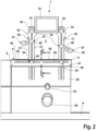
- Fig.2 shows a schematic front view of a further embodiment of a device 1 according to the invention for transmitting a position of at least one local feature 2c of a wall section 3 to a tile (not shown) that can be arranged on the wall section 3.
- the feature 2c is designed as a rectangular dummy for a flushing actuation unit (not shown) that can be arranged on the wall section 3.
- the device 1 has a support rail 4 arranged horizontally on the wall section 3.
- the support rail 4 has a vertically aligned support section 5, a horizontally aligned upper support section 6 and a horizontally aligned lower section 40.
- the upper support section 6 is placed on an upper edge of a tile 29 already arranged on the wall section 3 and is angled at right angles from the support section 5 in the direction of the wall section 3.
- the lower section 40 is angled at right angles from the support section 5 in the opposite direction to the upper support section 6 and thus points away from the wall section 3.
- the upper support section 6 and the lower section 40 are aligned parallel to one another.
- the device 1 has two in a parallel to the plane of the drawing of Fig.2
- the device has positioning elements 30 of the same design that are connected to the support rail 4 in a way that is adjustable at a given level.
- Each positioning element 30 is elongated and has a constant width over most of its length.
- An elongated opening 17 is formed in the middle of the respective positioning element 30, along which the respective positioning element 30 is connected to the support rail 4 in an adjustable manner in its longitudinal direction.
- the respective positioning element 30 presents the viewer of Fig.2 facing stiffening bends 31, which give the respective positioning element 30 a higher dimensional stability.
- a free positioning end section of the respective positioning element 30 On a free positioning end section of the respective positioning element 30, two oppositely extending lateral contact shoulders 32 are arranged for contacting the positioning end section to the local situation 2c, wherein a free end section 33 of the respective positioning element 30 extends beyond the contact shoulders 32.
- the local situation 2c is in Fig.2 positively received between the two positioning end sections of the two positioning elements 30.
- the opening 17 of the respective positioning element 30 extends into an area of the respective positioning element 30 lying between the two contact shoulders 32 of the respective positioning element 30.
- a circular opening 34 is formed on the free end section 33 of the respective positioning element 30, which offers a further measuring option or template function.
- several slot-shaped openings 22 are formed on the respective free end section 33, which is associated with a saving in material and a reduction in weight.
- a Fig.2 towering so There is an angled portion 35 projecting away from the wall section 3, via which the respective positioning element 30 can be more easily operated manually.
- the device 1 has two fixing means 24 for fixing the respective positioning element 30 in a position relative to the application rail 4 on the application rail 4, wherein only one manually operable actuating head 25 of the fixing means 24 is shown.
- a section (not shown), in particular a threaded bolt section, of the respective fixing means 24 is guided through the opening 17 of the respective positioning element 30.
- two elongated openings 26 are formed which run in the longitudinal direction of the support rail 4 and are arranged in a row, along which the respective positioning element 30 is adjustably connected to the support rail 4 in the longitudinal direction of the support rail 4.
- the respective opening 26 of the support rail 4 extends over less than half the length of the support rail 4.
- a further section (not shown), in particular a further threaded bolt section, of the respective fixing means 24 is guided through the respective opening 26.
- the respective positioning element 30 runs on a side of the attachment section 5 of the attachment rail 4 facing the wall or the wall section 3.
- two elongated openings 36 are formed, which run in the longitudinal direction of the attachment rail 4 and are arranged in a row, through which the respective positioning element 30 is guided.
- the lengths of the openings 36 correspond to the lengths of the openings 26.
- the device 1 has two in a parallel to the plane of the drawing of Fig.2 arranged plane, adjustably connected to the respective positioning element 30, and two further fixing means 24 for fixing the respective template element 37 in a position relative to the respective positioning element 30 on the respective positioning element 30.
- the respective template element 37 is adjustably connected to the respective positioning element 30 along the opening 17 of the respective positioning element 30 in the longitudinal direction of the respective positioning element 30.
- An elongated opening 38 is formed on the respective template element 37, along which the respective template element 37 is connected to the respective positioning element 30 in a way that is adjustable in its longitudinal direction.
- the respective template element 37 has a ring-shaped template end section 39. Using the ring-shaped template end section 39, a circular marking line can be drawn on the tile to be machined as an orientation aid for a drilling or milling process.
- the template end sections 39 can be used to mark additional screw holes, switch boxes or hole cutouts.
- the additional fixing means 24 has a knurled screw 25, of which only an actuating head can be seen.
- the additional fixing means 24 has a nut (not shown) screwed onto a threaded shaft (not shown) of the knurled screw 25, which passes through the opening 17 on the positioning element 30 and the opening 38 on the template element 37, which nut partially engages in the opening 38 of the template element 37 in order to be secured against twisting when the additional fixing means 24 is tightened.
- Contact elements 41 are arranged at the ends of the contact section 5 of the contact rail 4, each of which can have a rubber-elastic element (not shown) via which the contact section 5 contacts the tile 29 in order to stabilize the contact rail 4 or the device 1.
- the support rail 4 is first arranged left-aligned to a left edge of the tile 29 already arranged on the wall below the wall section 3, as shown in Fig.2 is shown.
- the fixing means 24 can then be released so that the positioning elements 30 can be displaced along the openings 26 of the support rail 4 and along the openings 17 of the positioning elements 30 relative to the support rail 4 until the support shoulders 32 of the positioning elements 30 are as shown in Fig.2 shown on the local situation 2c.
- the fixing means 24 can be tightened again in order to fix the positioning elements 30 in their relative positions on the support rail 4.
- the device 1 can then be removed from the wall and placed on the tile to be processed.
Landscapes
- Engineering & Computer Science (AREA)
- Architecture (AREA)
- Civil Engineering (AREA)
- Structural Engineering (AREA)
- Mechanical Engineering (AREA)
- Finishing Walls (AREA)
Applications Claiming Priority (1)
| Application Number | Priority Date | Filing Date | Title |
|---|---|---|---|
| DE102022129978.3A DE102022129978A1 (de) | 2022-11-14 | 2022-11-14 | Vorrichtung zum Übertragen einer Position von wenigstens einer lokalen Gegebenheit eines Wandabschnitts auf eine an dem Wandabschnitt anordbare Wandverkleidungsplatte |
Publications (3)
| Publication Number | Publication Date |
|---|---|
| EP4372182A1 true EP4372182A1 (fr) | 2024-05-22 |
| EP4372182B1 EP4372182B1 (fr) | 2025-12-17 |
| EP4372182C0 EP4372182C0 (fr) | 2025-12-17 |
Family
ID=88745848
Family Applications (1)
| Application Number | Title | Priority Date | Filing Date |
|---|---|---|---|
| EP23208475.6A Active EP4372182B1 (fr) | 2022-11-14 | 2023-11-08 | Dispositif pour transférer une position d'au moins une donnée locale d'une section de paroi à un panneau de revêtement de paroi pouvant être disposé sur la section de paroi |
Country Status (2)
| Country | Link |
|---|---|
| EP (1) | EP4372182B1 (fr) |
| DE (1) | DE102022129978A1 (fr) |
Citations (5)
| Publication number | Priority date | Publication date | Assignee | Title |
|---|---|---|---|---|
| DE19510557A1 (de) | 1995-03-23 | 1995-08-24 | Andreas Bordag | Anzeichnungshilfe für Installationslöcher in engfugig verlegten Wandbekleidungen aus Fliesen, Platten und Mosaik |
| DE20014981U1 (de) | 2000-04-18 | 2000-12-14 | Kölsch, Lutz, 13509 Berlin | Gerät zum Anzeichnen von Ausschnitten und/oder Winkeln beim Verlegen platten- oder tafelförmiger Bauelemente |
| GB2475777A (en) * | 2009-11-23 | 2011-06-01 | Martin Hemingway | Tiling support and leveller |
| DE102015004948A1 (de) | 2015-04-18 | 2016-10-20 | Michael H. Föhlings | Leicht handhabbares kostengünstiges Verfahren und Schablone zur Fliesenanpassung an Bauteile in Fliesenspiegeln für jedermann |
| US20170066125A1 (en) * | 2015-09-09 | 2017-03-09 | Tad K. Lostlen | Transfer Tool for Cabinet Holes |
Family Cites Families (3)
| Publication number | Priority date | Publication date | Assignee | Title |
|---|---|---|---|---|
| DE29520357U1 (de) * | 1995-12-22 | 1996-06-13 | Schwaiger, Heinz J., 80539 München | Diagonalmehrfachwinkelgerät |
| US7254920B2 (en) * | 2003-04-18 | 2007-08-14 | Roland Steele | Tile-leveling device |
| GB201809759D0 (en) * | 2018-06-14 | 2018-08-01 | Mccorkell Tiernan | Pipe easy |
-
2022
- 2022-11-14 DE DE102022129978.3A patent/DE102022129978A1/de active Pending
-
2023
- 2023-11-08 EP EP23208475.6A patent/EP4372182B1/fr active Active
Patent Citations (5)
| Publication number | Priority date | Publication date | Assignee | Title |
|---|---|---|---|---|
| DE19510557A1 (de) | 1995-03-23 | 1995-08-24 | Andreas Bordag | Anzeichnungshilfe für Installationslöcher in engfugig verlegten Wandbekleidungen aus Fliesen, Platten und Mosaik |
| DE20014981U1 (de) | 2000-04-18 | 2000-12-14 | Kölsch, Lutz, 13509 Berlin | Gerät zum Anzeichnen von Ausschnitten und/oder Winkeln beim Verlegen platten- oder tafelförmiger Bauelemente |
| GB2475777A (en) * | 2009-11-23 | 2011-06-01 | Martin Hemingway | Tiling support and leveller |
| DE102015004948A1 (de) | 2015-04-18 | 2016-10-20 | Michael H. Föhlings | Leicht handhabbares kostengünstiges Verfahren und Schablone zur Fliesenanpassung an Bauteile in Fliesenspiegeln für jedermann |
| US20170066125A1 (en) * | 2015-09-09 | 2017-03-09 | Tad K. Lostlen | Transfer Tool for Cabinet Holes |
Also Published As
| Publication number | Publication date |
|---|---|
| DE102022129978A1 (de) | 2024-05-16 |
| EP4372182B1 (fr) | 2025-12-17 |
| EP4372182C0 (fr) | 2025-12-17 |
Similar Documents
| Publication | Publication Date | Title |
|---|---|---|
| EP2154297B1 (fr) | Agencement de douche | |
| DE29607127U1 (de) | Höhenverstellbarer Drainagerost | |
| EP4372182A1 (fr) | Dispositif pour transférer une position d'au moins une donnée locale d'une section de paroi à un panneau de revêtement de paroi pouvant être disposé sur la section de paroi | |
| EP3922784B1 (fr) | Dispositif de nivellement et lissage de chapes | |
| DE8615470U1 (de) | Rohrführungsbogen | |
| DE102013001234B4 (de) | Anordnung einer Vorrichtung für einen in der Nähe einer Wand angeordneten Bodenablauf | |
| DE19523994C2 (de) | Anreißschablone für Elektroinstallationsdosen | |
| DE29516040U1 (de) | Tragstütze sowie Tragvorrichtung mit wenigstens vier im Abstand zueinander angeordneten Tragstützen | |
| DE20111012U1 (de) | Anordnung zur Verlegung von Dacheindeckungsteilen auf der Lattung eines Daches | |
| EP1360441B1 (fr) | Dispositif de guidage destine a un tuyau installe dans un revetement de beton | |
| CH695905A5 (de) | Abstand- und Distanzhalter. | |
| DE9319667U1 (de) | Vorrichtung zum Bearbeiten, insbesondere Verputzen von Laibungen | |
| DE29919446U1 (de) | Haltevorrichtung für eine Deckenrandschalung | |
| DE202017104959U1 (de) | Mutter für einen Schiebebolzen | |
| EP0731235A1 (fr) | Dispositif de montage pour protection solaire | |
| EP1323933B1 (fr) | Fixation pour un rail allongé ayant un profil en C avec l'ouverture dirigée vers le bas | |
| DE29707090U1 (de) | Vorrichtung zur Wandmontage mindestens eines sanitären Gegenstandes | |
| EP2143357B1 (fr) | Profilé longitudinal, douille enfichable et construction portante à partir d'un profilé longitudinal et d'une douille enfichable | |
| DE202022106233U1 (de) | Fassadenrinne | |
| DE9310462U1 (de) | Wannenträger | |
| DE7046013U (de) | Vorrichtung zum Halten von Dachrinnen | |
| DE10046223A1 (de) | Halterung für einen mit Laschen versehenen Heizkörper | |
| DE202023100697U1 (de) | Podest für Bühnen | |
| EP3964655A1 (fr) | Élément de fixation | |
| EP0434603A1 (fr) | Dispositif pour la fixation de la distance entre deux parois de coffrage opposées |
Legal Events
| Date | Code | Title | Description |
|---|---|---|---|
| PUAI | Public reference made under article 153(3) epc to a published international application that has entered the european phase |
Free format text: ORIGINAL CODE: 0009012 |
|
| STAA | Information on the status of an ep patent application or granted ep patent |
Free format text: STATUS: THE APPLICATION HAS BEEN PUBLISHED |
|
| AK | Designated contracting states |
Kind code of ref document: A1 Designated state(s): AL AT BE BG CH CY CZ DE DK EE ES FI FR GB GR HR HU IE IS IT LI LT LU LV MC ME MK MT NL NO PL PT RO RS SE SI SK SM TR |
|
| STAA | Information on the status of an ep patent application or granted ep patent |
Free format text: STATUS: REQUEST FOR EXAMINATION WAS MADE |
|
| 17P | Request for examination filed |
Effective date: 20240822 |
|
| RBV | Designated contracting states (corrected) |
Designated state(s): AL AT BE BG CH CY CZ DE DK EE ES FI FR GB GR HR HU IE IS IT LI LT LU LV MC ME MK MT NL NO PL PT RO RS SE SI SK SM TR |
|
| RIC1 | Information provided on ipc code assigned before grant |
Ipc: E04F 21/00 20060101AFI20250606BHEP Ipc: B25H 7/02 20060101ALI20250606BHEP Ipc: E04G 21/18 20060101ALI20250606BHEP Ipc: E04F 21/18 20060101ALI20250606BHEP |
|
| GRAP | Despatch of communication of intention to grant a patent |
Free format text: ORIGINAL CODE: EPIDOSNIGR1 |
|
| STAA | Information on the status of an ep patent application or granted ep patent |
Free format text: STATUS: GRANT OF PATENT IS INTENDED |
|
| GRAS | Grant fee paid |
Free format text: ORIGINAL CODE: EPIDOSNIGR3 |
|
| INTG | Intention to grant announced |
Effective date: 20251009 |
|
| GRAA | (expected) grant |
Free format text: ORIGINAL CODE: 0009210 |
|
| STAA | Information on the status of an ep patent application or granted ep patent |
Free format text: STATUS: THE PATENT HAS BEEN GRANTED |
|
| AK | Designated contracting states |
Kind code of ref document: B1 Designated state(s): AL AT BE BG CH CY CZ DE DK EE ES FI FR GB GR HR HU IE IS IT LI LT LU LV MC ME MK MT NL NO PL PT RO RS SE SI SK SM TR |
|
| REG | Reference to a national code |
Ref country code: CH Ref legal event code: F10 Free format text: ST27 STATUS EVENT CODE: U-0-0-F10-F00 (AS PROVIDED BY THE NATIONAL OFFICE) Effective date: 20251217 Ref country code: GB Ref legal event code: FG4D Free format text: NOT ENGLISH |
|
| REG | Reference to a national code |
Ref country code: DE Ref legal event code: R096 Ref document number: 502023002490 Country of ref document: DE |
|
| U01 | Request for unitary effect filed |
Effective date: 20251222 |
|
| U07 | Unitary effect registered |
Designated state(s): AT BE BG DE DK EE FI FR IT LT LU LV MT NL PT RO SE SI Effective date: 20260112 |
|
| PG25 | Lapsed in a contracting state [announced via postgrant information from national office to epo] |
Ref country code: NO Free format text: LAPSE BECAUSE OF FAILURE TO SUBMIT A TRANSLATION OF THE DESCRIPTION OR TO PAY THE FEE WITHIN THE PRESCRIBED TIME-LIMIT Effective date: 20260317 |
|
| PG25 | Lapsed in a contracting state [announced via postgrant information from national office to epo] |
Ref country code: HR Free format text: LAPSE BECAUSE OF FAILURE TO SUBMIT A TRANSLATION OF THE DESCRIPTION OR TO PAY THE FEE WITHIN THE PRESCRIBED TIME-LIMIT Effective date: 20251217 |
|
| PG25 | Lapsed in a contracting state [announced via postgrant information from national office to epo] |
Ref country code: RS Free format text: LAPSE BECAUSE OF FAILURE TO SUBMIT A TRANSLATION OF THE DESCRIPTION OR TO PAY THE FEE WITHIN THE PRESCRIBED TIME-LIMIT Effective date: 20260317 |