EP4372919A1 - Borne et son procédé de traitement - Google Patents
Borne et son procédé de traitement Download PDFInfo
- Publication number
- EP4372919A1 EP4372919A1 EP22841487.6A EP22841487A EP4372919A1 EP 4372919 A1 EP4372919 A1 EP 4372919A1 EP 22841487 A EP22841487 A EP 22841487A EP 4372919 A1 EP4372919 A1 EP 4372919A1
- Authority
- EP
- European Patent Office
- Prior art keywords
- terminal
- terminal according
- conducting
- fixing portion
- silver
- Prior art date
- Legal status (The legal status is an assumption and is not a legal conclusion. Google has not performed a legal analysis and makes no representation as to the accuracy of the status listed.)
- Pending
Links
Images




Classifications
-
- H—ELECTRICITY
- H01—ELECTRIC ELEMENTS
- H01R—ELECTRICALLY-CONDUCTIVE CONNECTIONS; STRUCTURAL ASSOCIATIONS OF A PLURALITY OF MUTUALLY-INSULATED ELECTRICAL CONNECTING ELEMENTS; COUPLING DEVICES; CURRENT COLLECTORS
- H01R13/00—Details of coupling devices of the kinds covered by groups H01R12/70 or H01R24/00 - H01R33/00
- H01R13/02—Contact members
- H01R13/15—Pins, blades or sockets having separate spring member for producing or increasing contact pressure
- H01R13/187—Pins, blades or sockets having separate spring member for producing or increasing contact pressure with spring member in the socket
-
- H—ELECTRICITY
- H01—ELECTRIC ELEMENTS
- H01R—ELECTRICALLY-CONDUCTIVE CONNECTIONS; STRUCTURAL ASSOCIATIONS OF A PLURALITY OF MUTUALLY-INSULATED ELECTRICAL CONNECTING ELEMENTS; COUPLING DEVICES; CURRENT COLLECTORS
- H01R13/00—Details of coupling devices of the kinds covered by groups H01R12/70 or H01R24/00 - H01R33/00
- H01R13/02—Contact members
- H01R13/15—Pins, blades or sockets having separate spring member for producing or increasing contact pressure
-
- H—ELECTRICITY
- H01—ELECTRIC ELEMENTS
- H01R—ELECTRICALLY-CONDUCTIVE CONNECTIONS; STRUCTURAL ASSOCIATIONS OF A PLURALITY OF MUTUALLY-INSULATED ELECTRICAL CONNECTING ELEMENTS; COUPLING DEVICES; CURRENT COLLECTORS
- H01R13/00—Details of coupling devices of the kinds covered by groups H01R12/70 or H01R24/00 - H01R33/00
- H01R13/02—Contact members
- H01R13/03—Contact members characterised by the material, e.g. plating, or coating materials
-
- H—ELECTRICITY
- H01—ELECTRIC ELEMENTS
- H01R—ELECTRICALLY-CONDUCTIVE CONNECTIONS; STRUCTURAL ASSOCIATIONS OF A PLURALITY OF MUTUALLY-INSULATED ELECTRICAL CONNECTING ELEMENTS; COUPLING DEVICES; CURRENT COLLECTORS
- H01R13/00—Details of coupling devices of the kinds covered by groups H01R12/70 or H01R24/00 - H01R33/00
- H01R13/02—Contact members
- H01R13/10—Sockets for co-operation with pins or blades
- H01R13/11—Resilient sockets
- H01R13/111—Resilient sockets co-operating with pins having a circular transverse section
-
- H—ELECTRICITY
- H01—ELECTRIC ELEMENTS
- H01R—ELECTRICALLY-CONDUCTIVE CONNECTIONS; STRUCTURAL ASSOCIATIONS OF A PLURALITY OF MUTUALLY-INSULATED ELECTRICAL CONNECTING ELEMENTS; COUPLING DEVICES; CURRENT COLLECTORS
- H01R43/00—Apparatus or processes specially adapted for manufacturing, assembling, maintaining, or repairing of line connectors or current collectors or for joining electric conductors
- H01R43/16—Apparatus or processes specially adapted for manufacturing, assembling, maintaining, or repairing of line connectors or current collectors or for joining electric conductors for manufacturing contact members, e.g. by punching and by bending
-
- H—ELECTRICITY
- H01—ELECTRIC ELEMENTS
- H01R—ELECTRICALLY-CONDUCTIVE CONNECTIONS; STRUCTURAL ASSOCIATIONS OF A PLURALITY OF MUTUALLY-INSULATED ELECTRICAL CONNECTING ELEMENTS; COUPLING DEVICES; CURRENT COLLECTORS
- H01R11/00—Individual connecting elements providing two or more spaced connecting locations for conductive members which are, or may be, thereby interconnected, e.g. end pieces for wires or cables supported by the wire or cable and having means for facilitating electrical connection to some other wire, terminal, or conductive member, blocks of binding posts
- H01R11/03—Individual connecting elements providing two or more spaced connecting locations for conductive members which are, or may be, thereby interconnected, e.g. end pieces for wires or cables supported by the wire or cable and having means for facilitating electrical connection to some other wire, terminal, or conductive member, blocks of binding posts characterised by the relationship between the connecting locations
- H01R11/05—Individual connecting elements providing two or more spaced connecting locations for conductive members which are, or may be, thereby interconnected, e.g. end pieces for wires or cables supported by the wire or cable and having means for facilitating electrical connection to some other wire, terminal, or conductive member, blocks of binding posts characterised by the relationship between the connecting locations the connecting locations having different types of direct connections
Definitions
- the present application relates to the technical field of electrical components, in particular to a terminal and a processing method thereof.
- Wire harnesses are commonly used in electrical connections to conduct current and transmit signals.
- a terminal of the wire harness is equipped with a plug-in terminal that is used for being connected with a corresponding wire.
- the plug-in terminals can be can be classified as male terminals, and female terminals that can be fit with the male terminals.
- the female terminal is provided with a hole into which the male terminal can be inserted, so that the male terminal and the female terminal are plugged with each other, and the male terminal and the female terminal are in contact with each other to conduct electricity through the contact area.
- the existing plug-in terminal has the technical problems of large contact resistance and high temperature rise at the connection position.
- An embodiment of the first aspect of the present application provides a terminal including a connecting portion, a first fixing portion and a conducting portion that are connected in sequence.
- the connecting portion is used for being connected to a cable.
- the conducting portion includes a plurality of elastic sheets that are distributed at intervals in a circumferential direction. First ends of the elastic sheets are all fixedly connected to the first fixing portion, and a first groove is arranged between any two adjacent elastic sheets.
- An embodiment of the second aspect of the present application provides a processing method of a terminal, including:
- the terminal can be used as a male terminal or a female terminal.
- the elastic sheets can be expanded outward due to their own elasticity, so as to be in close contact with the mating female terminal, so that, on the one hand, the reliability of the connection is ensured to avoid loosening, and on the other hand, the elastic sheets can keep fitting with the female terminal by their own elasticity, thus increasing the contact area of plug-in fitting.
- the elastic sheets When the terminal is used as a female terminal, the elastic sheets can be contracted inward due to their own elasticity, so as to be in close contact with the mating male terminal, so that, on the one hand, the reliability of the connection is ensured to avoid loosening, and on the other hand, the elastic sheets can keep fitting with the male terminal by their own elasticity, thus increasing the contact area of the plug-in fitting.
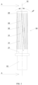
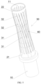
- An embodiment of the first aspect of the present application provides a terminal, as shown in FIGs. 1 and 5 , the terminal includes a connecting portion 10, a first fixing portion 21 and a conducting portion 30 that are connected in sequence.
- the connecting portion 10 is used for being connected to a cable.
- the conducting portion 30 includes a plurality of elastic sheets 31 that are arranged at intervals in a circumferential direction. First ends of the elastic sheets 31 are all fixedly connected to the first fixing portion 21.
- a first groove 32 is arranged between any two adjacent elastic sheets 31.
- the terminal can be used as a male terminal or a female terminal.
- the elastic sheets 31 can be expanded due to their own elasticity, so as to be in close contact with the mating female terminal, so that, on the one hand, the reliability of the connection is ensured to avoid loosening, and on the other hand, the elastic sheets 31 can keep fitting with the female terminal by their own elasticity, thus increasing the contact area of plug-in fitting.
- the elastic sheets 31 can be contracted inward due to their own elasticity, so as to be in close contact with the mating male terminal, so that, on the one hand, the reliability of the connection is ensured to avoid loosening, and on the other hand, the elastic sheets 31 can keep fitting with the male terminal by their own elasticity, thus increasing the contact area of the plug-in fitting.
- the terminal has the following advantages: (1) the terminal can ensure reliability of mechanical connection of the plug-in fitting, and there is elasticity during plug-in to avoid loosening; (2) the terminal can increase the contact area of the plug-in fitting, resulting in small contact resistance and improving conductive property; (3) the terminal can reduce the temperature rise of the contact area during current conduction, which can avoid reduction in elasticity of the terminal, reduce the deformation, and prolong the service life of the terminal; (4) the terminal is easy to process and install, the processing is simple, thereby saving the material and saving the cost.
- the terminal includes a second fixing portion 22 located at one end of the conducting portion 30 that faces away from the first fixing portion 21, and the second ends of the elastic sheets 31 are all fixedly connected to the second fixing portion 22.
- both ends of the first groove 32 are closed, which further improves reliability of mechanical connection of the plug-in fitting, thereby avoiding loosening.
- the terminal is provided with a terminal hole 11 that extends throughout the second fixing portion 22 and the conducting portion 30, and the terminal is a female terminal.
- An external terminal can be inserted into the terminal hole 11.
- a cylinder structure that sleeves on the outer side of the conducting portion 30 is eliminated, thereby saving the material, reducing the processing and assembly difficulty, making the processing simpler, and reducing the cost.
- an end portion of the terminal hole 11 that faces away from the first fixing portion 21 is chamfered or rounded to facilitate the external terminal to enter into the terminal hole 11 during plug-in.
- the conducting portion 30 includes an inward recessed portion 40, as shown in FIGs. 5 to 7 , an inner diameter of the inward recessed portion 40 gradually increases from a center of the inward recessed portion 40 to both ends thereof.
- an inner diameter of the inward recessed portion 40 gradually increases from a center of the inward recessed portion 40 to both ends thereof.
- the first grooves 32 are disposed obliquely to the axis 12 of the terminal, and the elastic sheets 31 are also disposed obliquely to the axis 12 of the terminal.
- the inclined elastic sheets 31 can generate a large resistance to the external terminal to prevent the external terminal from exiting outward in the axis 12 of the terminal, and at the same time prevent the external terminal from rotating around the axis 12 of the terminal, so that the external terminal is more securely connected to the terminal.
- An angle of inclination of the first grooves 32 with respect to the axis 12 of the terminal is equal to an angle of inclination of the elastic sheets 31 with respect to the axis 12 of the terminal.
- the first grooves 32 is disposed obliquely to the axis 12 of the terminal in a nonlimiting way, and for example, a longitudinal boundary line of a first groove 32 is located in a plane that is disposed obliquely to the axis 12 of the terminal, so that the first groove 32 extends obliquely with respect to the axis 12 of the terminal, and the angles of inclination of tangent lines at different positions of the first groove 32 in longitudinal direction of the first groove 32 with respect to the axis 12 of the terminal are different.
- the inventor has made further improvements to the terminal as follows: the angles between tangent lines of the first groove 32 at all positions of the first groove 32 and the axis 12 of the terminal are equal, which can further improve stability of the connection between the terminal and the external terminal as well as conductive performance. Further, as shown in FIG. 2 , the angle ⁇ between the tangent line of the first groove 32 and the axis 12 of the terminal is 10° to 60°.
- the conducting portion 30 and the first fixing portion 21 are connected together by crimping, welding, or screw connection.
- the conducting portion 30 includes a plurality of independent elastic sheets 31, and one ends of the elastic sheets 31 are fixed to the first fixing portion 21, so that the elastic sheets 31 are distributed at intervals in the circumferential direction.
- the one ends of the elastic sheets 31 may be fixed to the first fixing portion 21 by crimping, welding, or screw connection.
- the conducting portion 30 and the first fixing portion 21 are integrally formed.
- the first fixing portion 21 and the conducting portion 30 can be an integral hollow cylinder structure, and a plurality of first grooves 32 are provided on the wall of the cylinder, so that an elastic sheet 31 is formed between any two adjacent first grooves 32, which reduces the difficulty of assembling and processing the terminal and is conducive to cost saving.
- the terminal includes a conducting cylinder 50 that sleeves on the outer side of the conducting portion 30, the conducting cylinder 50 is provided with second grooves 51 extending in the axial direction of the terminal, the elastic sheets 31 can enter into the second grooves 51, and the conducting cylinder 50 and the conducting portion 30 form a double-layer structure.
- an external terminal inserted into the terminal drives the elastic sheets 31 of the conducting portion 30 to expand outward and to enter into the second grooves 51, such that the conducting cylinder 50 and the conducting portion 30 both comes into contact with the external terminal, which increases the contact area between the terminal and the external terminal, improves the conductive performance, and improves stability of the connection between the terminal and the external terminal, and better prevents the external terminal from rotating relative to the terminal.
- a gap is provided between the conducting cylinder 50 and the conducting portion 30, that is, a deformation space for the conducting portion 30 to expand outwards is provided between the inner wall of the conducting cylinder 50 and the outer wall of the conducting portion 30.
- the conducting cylinder 50 is elastic, and can expands outward by the extrusion of the external terminal.
- the second grooves 51 are disposed obliquely to the axis 12 of the terminal, and the elastic sheets 31 are aligned with the second grooves 51, respectively.
- the angle of inclination of the second groove 51 is equal to the angle of inclination of the elastic sheet 31. In some other cases, the angle of inclination of the second groove 51 is not equal to the angle of inclination of the elastic sheet 31.
- the angle of inclination of the second groove 51 is smaller than the angle of inclination of the elastic sheet 31.
- the conducting cylinder 50 is provided with a cylinder recess portion 52, an inner diameter of which gradually increases from the center of the cylinder recess portion 52 to both ends thereof.
- the cylinder recess portion 52 can expand outward by the extrusion of the external terminal that is inserted into the terminal. Both the cylinder recess portion 52 and the inward recessed portion 40 can exert extrusion force on the external terminal at the same time to improve the stability of the connection.
- the recessed degree of the cylinder recess portion 52 is greater than the recessed degree of the inward recessed portion 40, which facilitates simultaneous contact of both the conducting cylinder 50 and the elastic sheet 31 with the external terminal, thereby increasing the contact area.
- the conducting cylinder 50 and the conducting portion 30 may be an integrated mechanism.
- the ratio of the surface area of the portion of the elastic sheet that enters into the second groove to the surface area of the second groove is 50% to 90%, to ensure sufficient contact area, thereby ensuring that the electric conductivity meets the actual needs.
- the inventor selects conducting cylinders 50 of the same specification and ten kinds of conducting portions 30 of different sizes for testing.
- the ratios of the surface area of the portion of the elastic sheet that enters into the second groove to the surface area of the second groove are 45%, 50%, 55%, 60%, 65%, 70%, 75%, 80%, 85%, 90%, 95%, respectively.
- the inventor selects the most suitable range of the ratio of the surface area of the portion of the elastic sheet that enters into the second groove to the surface area of the second groove to be 50% to 90%.
- the conducting portion 30 and/or the conducting cylinder 50 are made of a material containing tellurium.
- the material of the conducting portion 30 and/or the conducting cylinder 50 has a content of tellurium of 0.1% to 5%.
- the conducting portion 30 and/or the conducting cylinder 50 are made of tellurium-copper alloy, so that the terminal has good conductive performance and free-cutting property, thereby ensuring the electrical property and improving the processability, and the elasticity of the tellurium-copper alloy is also excellent.
- the tellurium-copper alloy has a content of tellurium of 0.2% to 1.2%.
- the inventor selects ten terminals of the same shape for testing.
- the conducting portions 30 of the terminals have the same size and are all made of tellurium-copper alloy, and the conducting cylinders 50 of the terminals have the same size and are all made of tellurium-copper alloy.
- the content of tellurium is 0.05%, 0.1%, 0.2%, 0.5%, 0.8%, 1.2%, 2%, 3%, 5%, 6%, 7%, respectively.
- the conducting portion 30 and the conducting cylinder 50 are provided with a plating layer to improve corrosion resistance, improve conductive performance, increase the number of times of plugging, and better prolong the service life of the conducting portion 30 and the conducting cylinder 50.
- the plating layer can be made by electroplating, chemical plating, magnetron sputtering or vacuum plating or the like.
- the electroplating is a process of plating, on a surface of some metal, a thin layer of other metal or alloy by using electrolysis principle.
- the chemical plating is a deposition process that produces a metal through a controllable oxidation-reduction reaction under a metal catalytic action.
- the magnetron sputtering is to use an interaction of a magnetic field and an electric field to make electrons move spirally near a target surface, thereby increasing the probability that electrons bombard argon to generate ions.
- the generated ions bombard the target surface under the action of the electric field so as to sputter a target material.
- the vacuum plating is to deposit various metal and non-metal films on the surface of plastic parts by means of distillation or sputtering under a vacuum condition.
- the plating layers on the conducting portion 30 and the conducting cylinder 50 have the same thickness. Since the plating layers have the same thickness, they can be electroplated in one time during the processing, and there is no need to carry out complex electroplating processing in order to obtain different thicknesses of the plating layers in different regions, so as to save processing costs and reduce electroplating pollution.
- the material of the plating layer on the conducting portion 30 is not the same with that of the plating layer on the conducting cylinder 50.
- Different plating layers can be selected according to the need. For example, a combination with higher electric conductivity may be selected according to the need, or a combination with better corrosion resistance may be selected, or a combination that is most suitable for the actual working environment may be selected by taking various factors into consideration.
- the plating layer is made of one or more selected from the group consisting of gold, silver, nickel, tin, zinc, tin-lead alloy, silver-antimony alloy, palladium, palladium-nickel alloy, graphite-silver, graphene-silver and silver-gold-zirconium alloy.
- Copper as an active metal, undergoes an oxidation reaction with oxygen and water during use, therefore, one or more inactive metals are needed to make the plating layer to prolong the service life of the terminal.
- a metal with good wear resistant is needed to make the plating layer, which can greatly prolong the service life of the contact.
- the contact needs excellent conductive property, and the above-mentioned metals have better electric conductivity and stability than the copper or copper alloys, thereby making the terminal obtain better electrical property and longer service life.
- the inventor adopts terminal samples and mating terminals to carry out a series of tests on the number of times of plugging and unplugging and the corrosion resistance time.
- the terminal samples have the same specification and the same material, and have plating layers with different materials.
- the mating terminals have the same specification.
- the inventor also adopts tin, nickel and zinc as the materials of the plating layer for the experiment. The experimental results are shown in Table 4 below.
- the numbers of times of plugging and unplugging in Table 4 are obtained as follows: the terminals are fixed on the experiment platform respectively; a mechanical device is used to simulate the plugging and unplugging of the terminals; and after every 100 times of plugging and unplugging, stop plugging and unplugging and observe the damage of the plating layer on the surface of the terminal.
- the experiment is stopped and the number of times of plugging and unplugging at that time is recorded. In this embodiment, if the number of times of insertion and removal is less than 8000, it is considered as unqualified.
- the test on corrosion resistance time in Table 4 below is to put the terminal into a salt fog spraying test chamber, spray salt fog to each position of the terminal, and take the terminal out every 20 hours to clean the terminal and observe surface corrosion of the terminal, which is a cycle.
- the corrosion area of the surface of the terminal is greater than 10% of the total area of the surface of the terminal, the test is stopped and the number of cycles at that time is recorded. In this embodiment, if the number of cycles is less than 80, it is considered as unqualified.
- the material of the plating layer is commonly used metal, such as tin, nickel and zinc
- the experimental results are far inferior to the selected metals.
- the plating layer made of nickel is qualified in the experiment of the number of times of plugging and unplugging, it is not outstanding and is not qualified in the salt spray experiment.
- the selected metals are used, the experimental results are much greater than the standard value, and the performance is stable. Therefore, the inventor selects the material of the plating layer to be one or more selected from the group consisting of gold, silver, silver-antimony alloy, graphite-silver, graphene-silver, palladium-nickel alloy, tin-lead alloy, and silver-gold-zirconium alloy.
- Table 4 Influence of different materials of the plating layer on the number of times of plugging and unplugging and corrosion resistance of the terminal Different materials of the plating layer Gold Silver Silver - antim any Alloy Graph ite-silver Graph ene-silver Silver -gold-zircon ium Alloy Tin Nickel Pallad ium Pallad ium-nickel Alloy Tin-lead Alloy Zinc Number of Times of plugging and unplugging (times) 12400 11800 12200 12000 12700 12100 8200 8400 11100 12000 10000 8500 Number of Corrosion Resistance Test Cycles (times) 131 128 120 130 127 131 82 89 110 120 111 88
- the plating layer includes a bottom layer and a surface layer.
- the plating layer is made by a multilayer plating method.
- the conducting portion 30 and the conducting cylinder 50 After being processed, the conducting portion 30 and the conducting cylinder 50 have many gaps and holes on their surface and below their surface microscopic interfaces, and these gaps and holes will cause wear and corrosion of the conducting portion 30 and the conducting cylinder 50 during use. Therefore, firstly a bottom layer is plated on the surface of the conducting portion 30 and the surface of the conducting cylinder 50, respectively, to fill the gaps and holes, so that the surfaces of the conducting portion 30 and the conducting cylinder 50 are flat and have no holes, and then a surface layer is plated on the surface of the conducting portion 30 and the surface of the conducting cylinder 50, respectively, so that the plating layers are combined with the surfaces more firmly, and the surfaces are more smoothly. Since there are no gaps and holes on the surface of the plating layer, the wear resistance, corrosion resistance and electrical performance of the terminal are better, and the service life of the terminal is greatly prolonged.
- the bottom layer is made of one or more selected from the group consisting of gold, silver, nickel, tin, tin-lead alloy and zinc.
- the surface layer is made of one or more selected from the group consisting of gold, silver, nickel, tin, tin-lead alloy, silver-antimony alloy, palladium, palladium-nickel alloy, graphite-silver, graphene-silver and silver-gold-zirconium alloy.
- the bottom layer has a thickness of 0.01 ⁇ m to 12 ⁇ m.
- the bottom layer has a thickness of 0.1 ⁇ m to 9 ⁇ m.
- the surface layer has a thickness of 0.5 ⁇ m to 50 ⁇ m.
- the surface layer has a thickness of 1 ⁇ m to 35 ⁇ m.
- the inventor adopts terminal samples and mating terminals to carry out a series of tests on temperature rise and the corrosion resistance time.
- the terminal samples have the same specification and the same material, have nickel bottom layers of different thicknesses, and have silver surface layers of the same thickness.
- the mating terminals have same specification. The experimental results are shown in Table 5 below.
- the test on temperature rises in Table 5 is to supply the same current to the terminals and the mating terminals that are respectively plugged with each other, detect the temperatures of the terminals at the same position before the current supply and after the temperature is stable in a closed environment, and take a difference therebetween to obtain an absolute value. In this embodiment, if the temperature rise is greater than 50K, it is considered as unqualified.
- the test on corrosion resistance time in Table 5 is to put the terminal into a salt fog spraying test chamber, spray salt fog to each position of the terminal, and take the terminal out every 20 hours to clean the terminal and observe surface corrosion of the terminal, which is a cycle.
- the corrosion area of the surface of the terminal is greater than 10% of the total area of the surface of the terminal, the test is stopped and the number of cycles at that time is recorded. In this embodiment, if the number of cycles is less than 80, it is considered as unqualified.
- the inventor selects the thickness of the bottom layer of the plating layer to be 0.01 ⁇ m to 12 ⁇ m.
- the thickness of the bottom layer of the plating layer is 0.1 ⁇ m to 9 ⁇ m, the combined effect of the temperature rise and corrosion resistance of the terminal is better. Therefore, in order to further improve the safety, reliability and practicality of the product itself, the thickness of the bottom layer of the plating layer is exemplarily 0.1 ⁇ m to 9 ⁇ m.
- the inventor adopts terminal samples and mating terminals to carry out a series of tests on temperature rise and the corrosion resistance time.
- the terminal samples have the same specification and the same material, have nickel bottom layers of the same thickness, and have silver surface layers of different thicknesses.
- the mating terminals have the same specification. The experimental results are shown in Table 6 below.
- the thickness of the silver surface layer is greater than 50 ⁇ m, the heat generated by the terminal cannot be radiated due to the bottom layer being too thick, which makes the temperature rise of the terminal unqualified, and in addition, the thick plating layer is easy to fall off the surface of the terminal, resulting in a decrease in the number of cycles of corrosion resistance.
- the material the surface layer of the plating layer is expensive metal, if the plating layer has a great thickness but fails to improve performance, it is not valuable for use. Therefore, the inventor selects the silver surface layer to be 0.1 ⁇ m to 50 ⁇ m.
- the inventor finds that when the thickness of the bottom layer of the plating layer is 1 ⁇ m to 35 ⁇ m, the combined effect of the temperature rise and corrosion resistance of the terminal is better. Therefore, in order to further improve the safety, reliability and practicality of the product itself, the thickness of the bottom layer of the plating layer is exemplarily 1 ⁇ m to 35 ⁇ m.
- the terminal is connected to the mating terminal through the conducting portion 30, and connected to the cable through the connecting portion 10.
- the connecting portion 10 may be of a cylindrical shape or a solid column shape or a solid plate shape.
- the cross section of the connecting portion 10 is of round, oval, polygon, flat, diamond, semi-arc, arc, or wavy shape.
- the cross section of the connecting portion 10 may be designed into various shapes, which is convenient for the designers to select terminals of different shapes according to the actual terminal layout environment, so as to reduce the volume of the plug-in structure, optimize the contact area, and improve the electrical performance of the terminal.
- the shape of the internal cross-section of the terminal is diverse, so that the terminal can be matched with the mating terminal of various shapes, which can provide more choices for the designers.
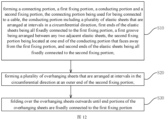
- the processing method of the terminal includes: step S10: forming a connecting portion 10, a first fixing portion 21, a conducting portion 30 and a second fixing portion 22, the connecting portion 10 being used for being connected to a cable, the conducting portion 30 including a plurality of elastic sheets 31 that are arranged at intervals in a circumferential direction, first ends of the elastic sheets 31 being all fixedly connected to the first fixing portion 21, a first groove 32 being arranged between any two adjacent elastic sheets 31, the second fixing portion 22 being located at one end of the conducting portion 30 that faces away from the first fixing portion 21, and the second ends of the elastic sheets 31 being all fixedly connected to the second fixing portion 22; step S20: forming a plurality of overhanging sheets that are arranged at intervals in the circumferential direction at an outer end of the second fixing portion 22; step S30: folding over the overhanging sheets outwards until end portions of the overhanging sheets are fixedly connected to the first fixing
- the conducting cylinder 50 and the conducting portion 30 can both come into contact with the external terminal, which increases the contact area between the terminal and the external terminal, improves the conductive performance, and can better prevent the external terminal from rotating relative to the terminal and improve stability of the connection between the terminal and the external terminal.
- the overhang sheets are firmly connected to the first fixing portion 21 by means of crimping, welding, and screw connection.
Landscapes
- Engineering & Computer Science (AREA)
- Manufacturing & Machinery (AREA)
- Manufacturing Of Electrical Connectors (AREA)
- Connector Housings Or Holding Contact Members (AREA)
- Connections Effected By Soldering, Adhesion, Or Permanent Deformation (AREA)
Applications Claiming Priority (3)
| Application Number | Priority Date | Filing Date | Title |
|---|---|---|---|
| CN202110803154.4A CN113410684A (zh) | 2021-07-15 | 2021-07-15 | 端子及其加工方法 |
| CN202121615279.6U CN216671958U (zh) | 2021-07-15 | 2021-07-15 | 端子 |
| PCT/CN2022/105966 WO2023284854A1 (fr) | 2021-07-15 | 2022-07-15 | Borne et son procédé de traitement |
Publications (2)
| Publication Number | Publication Date |
|---|---|
| EP4372919A1 true EP4372919A1 (fr) | 2024-05-22 |
| EP4372919A4 EP4372919A4 (fr) | 2025-02-12 |
Family
ID=84918998
Family Applications (1)
| Application Number | Title | Priority Date | Filing Date |
|---|---|---|---|
| EP22841487.6A Pending EP4372919A4 (fr) | 2021-07-15 | 2022-07-15 | Borne et son procédé de traitement |
Country Status (5)
| Country | Link |
|---|---|
| US (1) | US20240154338A1 (fr) |
| EP (1) | EP4372919A4 (fr) |
| JP (1) | JP7761747B2 (fr) |
| MX (1) | MX2024000812A (fr) |
| WO (1) | WO2023284854A1 (fr) |
Family Cites Families (13)
| Publication number | Priority date | Publication date | Assignee | Title |
|---|---|---|---|---|
| US4720157A (en) * | 1986-10-30 | 1988-01-19 | General Motors Corporation | Electrical connector having resilient contact means |
| JPH03155073A (ja) * | 1989-11-14 | 1991-07-03 | Amp Japan Ltd | 電気コネクタ用ソケット |
| US5676571A (en) * | 1996-08-08 | 1997-10-14 | Elcon Products International | Socket contact with integrally formed hood and arc-arresting portion |
| DE10235053A1 (de) * | 2002-07-31 | 2004-02-12 | Siemens Ag | Verfahren zur Herstellung eines Kontaktstückes |
| CN106816740A (zh) * | 2017-01-20 | 2017-06-09 | 上海航天科工电器研究院有限公司 | 一种电连接器母端子及其加工方法 |
| CN206850065U (zh) * | 2017-01-20 | 2018-01-05 | 得意精密电子(苏州)有限公司 | 筒状端子 |
| JP2018156772A (ja) * | 2017-03-16 | 2018-10-04 | 住友電装株式会社 | 雌端子、及び雌コネクタ |
| CN207282773U (zh) | 2017-05-24 | 2018-04-27 | 得意精密电子(苏州)有限公司 | 筒状端子 |
| CN107394445B (zh) | 2017-08-29 | 2023-08-08 | 实盈电子(东莞)有限公司 | 一种充电枪用导电连接件 |
| CN209045850U (zh) * | 2018-11-23 | 2019-06-28 | 广东纳特康电子股份有限公司 | 稳定性可靠的连接器母座 |
| CN210224392U (zh) | 2019-08-01 | 2020-03-31 | 富士康(昆山)电脑接插件有限公司 | 电连接器 |
| CN216671958U (zh) * | 2021-07-15 | 2022-06-03 | 长春捷翼汽车零部件有限公司 | 端子 |
| CN113410684A (zh) * | 2021-07-15 | 2021-09-17 | 长春捷翼汽车零部件有限公司 | 端子及其加工方法 |
-
2022
- 2022-07-15 JP JP2024501574A patent/JP7761747B2/ja active Active
- 2022-07-15 EP EP22841487.6A patent/EP4372919A4/fr active Pending
- 2022-07-15 WO PCT/CN2022/105966 patent/WO2023284854A1/fr not_active Ceased
- 2022-07-15 MX MX2024000812A patent/MX2024000812A/es unknown
-
2024
- 2024-01-16 US US18/413,053 patent/US20240154338A1/en active Pending
Also Published As
| Publication number | Publication date |
|---|---|
| JP2024526325A (ja) | 2024-07-17 |
| MX2024000812A (es) | 2024-02-06 |
| JP7761747B2 (ja) | 2025-10-28 |
| US20240154338A1 (en) | 2024-05-09 |
| EP4372919A4 (fr) | 2025-02-12 |
| WO2023284854A1 (fr) | 2023-01-19 |
Similar Documents
| Publication | Publication Date | Title |
|---|---|---|
| EP4391242A1 (fr) | Structure d'insertion de courroie plate et de borne, et véhicule à moteur | |
| JP2022137113A (ja) | コネクタシステムおよびコネクタシステムを製造する方法 | |
| US9004960B2 (en) | Connector with gold-palladium plated contacts | |
| EP4429035A1 (fr) | Structure de prise de charge à carte de circuit imprimé intégrée, et prise de charge | |
| EP4383464A1 (fr) | Structure de connexion électrique, siège de charge et automobile | |
| EP4391238A1 (fr) | Borne de prise, structure de prise et véhicule à moteur | |
| US20160344127A1 (en) | Electroconductive material with an undulating surface, an electrical terminal formed of said material, and a method of producing said material | |
| JP2024530659A (ja) | 電気接続構造、充電用コンセントおよび自動車 | |
| JP5261278B2 (ja) | コネクタおよびコネクタ用金属材料 | |
| CN216671958U (zh) | 端子 | |
| EP4372919A1 (fr) | Borne et son procédé de traitement | |
| US20250038444A1 (en) | Metal reed structure and electrical connector | |
| US10998108B2 (en) | Electrical contact material, method of producing an electrical contact material, and terminal | |
| EP4372925A1 (fr) | Borne à fonction de mémoire | |
| CN113410684A (zh) | 端子及其加工方法 | |
| EP4372922A1 (fr) | Borne cylindrique, structure de connexion enfichable et procédé d'usinage de borne cylindrique | |
| EP4372924A1 (fr) | Borne ayant un anneau de mémoire | |
| CN113794063B (zh) | 接线端子及端子接线结构 | |
| CN100388572C (zh) | 电连接器的盒式结构插孔接触件的局部电镀金方法 | |
| JP5199708B2 (ja) | タブ端子 | |
| US20230187866A1 (en) | Silver alloy clad structure for charging terminals and manufacturing method thereof | |
| CN100373711C (zh) | 端子及其电镀方法 | |
| US20260031561A1 (en) | Electroplated part, method for manufacturing electroplated part and connector | |
| JP2013161526A (ja) | 端子金具 | |
| EP4404392A1 (fr) | Support de charge pour un centrage de borne de haute précision et véhicule à moteur |
Legal Events
| Date | Code | Title | Description |
|---|---|---|---|
| STAA | Information on the status of an ep patent application or granted ep patent |
Free format text: STATUS: THE INTERNATIONAL PUBLICATION HAS BEEN MADE |
|
| PUAI | Public reference made under article 153(3) epc to a published international application that has entered the european phase |
Free format text: ORIGINAL CODE: 0009012 |
|
| STAA | Information on the status of an ep patent application or granted ep patent |
Free format text: STATUS: REQUEST FOR EXAMINATION WAS MADE |
|
| 17P | Request for examination filed |
Effective date: 20240116 |
|
| AK | Designated contracting states |
Kind code of ref document: A1 Designated state(s): AL AT BE BG CH CY CZ DE DK EE ES FI FR GB GR HR HU IE IS IT LI LT LU LV MC MK MT NL NO PL PT RO RS SE SI SK SM TR |
|
| P01 | Opt-out of the competence of the unified patent court (upc) registered |
Free format text: CASE NUMBER: APP_43252/2024 Effective date: 20240724 |
|
| DAV | Request for validation of the european patent (deleted) | ||
| DAX | Request for extension of the european patent (deleted) | ||
| REG | Reference to a national code |
Ref country code: DE Ref legal event code: R079 Free format text: PREVIOUS MAIN CLASS: H01R0013020000 Ipc: H01R0013110000 |
|
| A4 | Supplementary search report drawn up and despatched |
Effective date: 20250114 |
|
| RIC1 | Information provided on ipc code assigned before grant |
Ipc: H01R 13/03 20060101ALN20250108BHEP Ipc: H01R 11/05 20060101ALN20250108BHEP Ipc: H01R 43/16 20060101ALI20250108BHEP Ipc: H01R 13/187 20060101ALI20250108BHEP Ipc: H01R 13/11 20060101AFI20250108BHEP |