EP4391238A1 - Borne de prise, structure de prise et véhicule à moteur - Google Patents
Borne de prise, structure de prise et véhicule à moteur Download PDFInfo
- Publication number
- EP4391238A1 EP4391238A1 EP22857624.5A EP22857624A EP4391238A1 EP 4391238 A1 EP4391238 A1 EP 4391238A1 EP 22857624 A EP22857624 A EP 22857624A EP 4391238 A1 EP4391238 A1 EP 4391238A1
- Authority
- EP
- European Patent Office
- Prior art keywords
- plug
- terminal
- plating layer
- terminal according
- connection
- Prior art date
- Legal status (The legal status is an assumption and is not a legal conclusion. Google has not performed a legal analysis and makes no representation as to the accuracy of the status listed.)
- Pending
Links
Images

Classifications
-
- H—ELECTRICITY
- H01—ELECTRIC ELEMENTS
- H01R—ELECTRICALLY-CONDUCTIVE CONNECTIONS; STRUCTURAL ASSOCIATIONS OF A PLURALITY OF MUTUALLY-INSULATED ELECTRICAL CONNECTING ELEMENTS; COUPLING DEVICES; CURRENT COLLECTORS
- H01R13/00—Details of coupling devices of the kinds covered by groups H01R12/70 or H01R24/00 - H01R33/00
- H01R13/02—Contact members
-
- H—ELECTRICITY
- H01—ELECTRIC ELEMENTS
- H01R—ELECTRICALLY-CONDUCTIVE CONNECTIONS; STRUCTURAL ASSOCIATIONS OF A PLURALITY OF MUTUALLY-INSULATED ELECTRICAL CONNECTING ELEMENTS; COUPLING DEVICES; CURRENT COLLECTORS
- H01R13/00—Details of coupling devices of the kinds covered by groups H01R12/70 or H01R24/00 - H01R33/00
- H01R13/02—Contact members
- H01R13/10—Sockets for co-operation with pins or blades
- H01R13/11—Resilient sockets
- H01R13/113—Resilient sockets co-operating with pins or blades having a rectangular transverse section
-
- H—ELECTRICITY
- H01—ELECTRIC ELEMENTS
- H01R—ELECTRICALLY-CONDUCTIVE CONNECTIONS; STRUCTURAL ASSOCIATIONS OF A PLURALITY OF MUTUALLY-INSULATED ELECTRICAL CONNECTING ELEMENTS; COUPLING DEVICES; CURRENT COLLECTORS
- H01R13/00—Details of coupling devices of the kinds covered by groups H01R12/70 or H01R24/00 - H01R33/00
- H01R13/02—Contact members
- H01R13/03—Contact members characterised by the material, e.g. plating, or coating materials
-
- H—ELECTRICITY
- H01—ELECTRIC ELEMENTS
- H01R—ELECTRICALLY-CONDUCTIVE CONNECTIONS; STRUCTURAL ASSOCIATIONS OF A PLURALITY OF MUTUALLY-INSULATED ELECTRICAL CONNECTING ELEMENTS; COUPLING DEVICES; CURRENT COLLECTORS
- H01R13/00—Details of coupling devices of the kinds covered by groups H01R12/70 or H01R24/00 - H01R33/00
- H01R13/02—Contact members
- H01R13/10—Sockets for co-operation with pins or blades
- H01R13/11—Resilient sockets
- H01R13/112—Resilient sockets forked sockets having two legs
-
- H—ELECTRICITY
- H01—ELECTRIC ELEMENTS
- H01R—ELECTRICALLY-CONDUCTIVE CONNECTIONS; STRUCTURAL ASSOCIATIONS OF A PLURALITY OF MUTUALLY-INSULATED ELECTRICAL CONNECTING ELEMENTS; COUPLING DEVICES; CURRENT COLLECTORS
- H01R2201/00—Connectors or connections adapted for particular applications
- H01R2201/26—Connectors or connections adapted for particular applications for vehicles
Definitions
- the present disclosure relates to the technical field of electrical connection elements, and particularly to a plug terminal, a plug structure and a motor vehicle.
- the sheet-shaped terminal and the clamping terminal are conventional conductive elements for plugging.
- the clamping terminal is clamped by the elasticity of a metal plate, and when being subjected to an external force or a long-term plugging vibration, the metal plate is easily deformed or its elasticity is weakened, so that an electrical connection is failed and the function of the electrical apparatus cannot be realized.
- An objective of the present disclosure is to provide a plug-in terminal, a plug-in structure, and a motor vehicle, so as to alleviate the technical problem that a failure of an electrical connection is likely to occur when a clamping terminal is subjected to an external force or a long-term plugging vibration.
- the present disclosure provides a plug-in terminal, including a terminal lamination.
- the terminal lamination includes at least two connection arms, each of the connection arms includes an overhanging end and a fixed end, and the fixed ends of the connection arms are fixedly connected together.
- a plugging groove is disposed between adjacent two of the connection arms.
- the overhanging end is provided with a conductive contact portion.
- the present disclosure provides a plug-in structure, including the aforementioned plug-in terminal and a mating plug-in terminal plugged therewith.
- the present disclosure provides a motor vehicle, including the aforementioned plug-in terminal.
- the present disclosure provides a motor vehicle, including the aforementioned plug-in structure.
- the mating plug-in terminal may be plugged and matched with the plug-in terminal, and in the plug-in terminal, connection arms of the plurality of terminal laminations are stacked, so that the mating plug-in terminal can be plugged into the plugging groove, and the problems of deformation and elasticity weakening caused by the excessively thick metal plate can be alleviated by the structure of the connection arms.
- the conductive contact portion is in in contact with and electrically connected to the connection arm; the mating plug-in terminal is tightly clamped by the connection arm, and fixed with the plug-in terminal together with a larger contact area therebetween, thereby ensuring the connection reliability and the electrical conduction effect.
- the plug-in terminal can ensure a stable clamping structure, reduce the deformation and increase the strength of the connection arm.
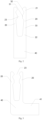
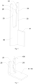
- the present disclosure provides a plug-in terminal, as illustrated in FIGS. 1 and 2 , including a terminal lamination 10 which includes at least two connection arms 20.
- Each of the connection arms 20 includes an overhanging end 21 and a fixed end 22, and the fixed end 22 of each connection arm 20 is fixedly connected together.
- a plugging groove 23 is disposed between adjacent two of the connection arms 20.
- Each of the connection arm 20 is provided with conductive contact portions 31.
- the conductive contact portions 31 are disposed inside the plugging groove 23, the mating plug-in terminal 50 may be plugged and matched with the plug-in terminal, and the mating plug-in terminal 50 is capable of being plugged into the plugging groove 23.
- the conductive contact portions 31 are in contact with the mating plug-in terminal 50 to realize an electrical connection, thereby ensuring the connection reliability and the electrical conduction effect.
- the conductive contact portion 31 is disposed on two sides inside the plugging groove 23, and is capable of being in contact with two sides of the mating plug-in terminal 50 respectively to realize electrical connection and increase a contact area to achieve a better electrical conduction effect.
- the conductive contact portions 31 are symmetrically disposed on two sides inside the plugging groove 23.
- the opposite conductive contact portions 31 are symmetrically disposed inside the plugging groove 23 to achieve a balanced stress and a better clamping effect.
- the mating plug-in terminal 50 may be plugged and matched with the plug-in terminal, and the plug-in terminal includes a plurality of terminal laminations 10 which are stacked.
- the mating plug-in terminal 50 is capable of being plugged into the plugging groove 23, and the conductive contact portions 31 are in contact with and electrically connected to the connection arm 20.
- the mating plug-in terminal 50 is tightly clamped by the connection arm 20, and fixed with the plug-in terminal together with a larger contact area therebetween, thereby ensuring the connection reliability and the electrical conduction effect.
- the plug-in terminal can ensure a stable clamping structure, reduce the deformation and increase the strength of the connection arm 20.
- the terminal laminations 10 are formed as sheets by punching a plate or cutting a plate, and are stacked so that the plug-in terminal has a high mechanical connection performance, while ensuring the conductive connection performance between the plug-in terminal and the mating plug-in terminal 50.
- the processing mode of punching a plate or cutting the plate is simple and the process is mature, so that the terminal laminations 10 can be processed rapidly in large batches, thereby saving the processing cost and improving the production efficiency.
- the mating plug-in terminal 50 matched with the plug-in terminal may be sheets or boards.
- the clamping force is controlled by adjusting the width of the connection arm 20 or the number of the terminal laminations 10, so as to adapt to the mating plug-in terminal 50 and meet various plugging requirements.
- the terminal lamination 10 includes two connection arms 20 with a plugging groove 23 formed therebetween, and the mating plug-in terminal 50 is capable of being plugged into the plugging groove 23.
- the terminal lamination 10 may include two or more connection arms 20, the terminal lamination 10 includes a plurality of plugging grooves 23, and a plurality of mating plug-in terminals 50 are plugged and matched with the plug-in terminal simultaneously.
- the terminal lamination 10 includes a terminal fixing portion 40 to which the fixed end 22 of each connection arm 20 is fixedly connected, and the connection arm 20 is connected to a cable through the terminal fixing portion 40, thereby ensuring the stability of the electrical connection.
- terminal fixing portions 40 of adjacent two of the terminal laminations 10 are connected together by crimping connection, welding connection, threaded connection or rivet connection.
- the crimping connection is a production process in which the adjacent terminal fixing portions 40 are assembled and then stamped into a whole by a crimping machine.
- the crimping connection is advantageous in mass production, and by using an automatic crimping machine, products with stable qualities can be manufactured rapidly in large quantities.
- the welding connection fuses the adjacent terminal fixing portions 40 into a whole through metal melting points by friction welding, resistance welding, ultrasonic welding, arc welding, pressure welding, laser welding, explosion welding, etc., so that the connection is firm and the contact resistance is small.
- the threaded connection means that the adjacent terminal fixing portions 40 both have threaded structures, which are capable of being threaded together or connected together by using separate studs and nuts.
- the threaded connection has the advantage of detachability, i.e., assembling and detaching can be repeated, which is suitable for scenarios that require frequent detaching.
- the rivet connection adopts rivets to rivet the adjacent terminal fixing portions 40 together.
- the rivet connection has the advantages of firm connection, simple processing method and easy operation.
- the structure of the terminal fixing portion 40 is not limited to one form.
- a first form is that the terminal fixing portion 40 is integrally formed, and the fixed end 22 of each of the connection arm 20 is fixedly connected to the terminal fixing portion 40.
- a second form is that the terminal fixing portion 40 is a part of the connection arm 20 and integrated therewith, while the plurality of terminal fixing portions 40 in the plug-in terminal are stacked.
- connection arms 20 of adjacent two of the terminal laminations 10 are in contact fit to slide relative to each other, so that each of the terminal laminations 10 is capable of maintaining its own clamping force, and the connection stability can be improved owing to the uneven surface of the plug-in terminal.
- connection arm 20 When the mating plug-in terminal 50 is plugged into the plugging groove 23, the connection arm 20 may be elastically deformed to tightly clamp the mating plug-in terminal 50 by an elastic force. Further, the connection arm 20 includes a deformation portion 33, and the conductive contact portion 31 and the deformation portion 33 are sequentially disposed in a direction from the overhanging end 21 to the fixed end 22. An inner wall of the deformation portion 33 is inclined inward in the direction from the overhanging end 21 to the fixed end 22, so as to promote the deformation of the connection arm 20, facilitate the plugging and unplugging of the mating plug-in terminal 50, and enhance the strength of clamping of the mating plug-in terminal 50.
- the overhanging end 21 of the connection arm 20 is chamfered or rounded to facilitate the plugging and matching with the mating plug-in terminal 50.
- connection arm 20 is provided with a scraping portion 32.
- the scraping portion 32 and the conductive contact portion 31 are sequentially disposed in the direction from the overhanging end 21 to the fixed end 22.
- the scraping portion 32 can scrape the foreign matter or oxide on the surface of the mating plug-in terminal 50 to expose a conductive surface of the mating plug-in terminal 50, thereby improving the electrical performance.
- the scraping portion 32 is disposed to extend in a thickness direction 100 of the terminal lamination 10.
- a movement direction of the mating plug-in terminal 50 is perpendicular to an extending direction of the scraping portion 32, which is beneficial to scraping the mating plug-in terminal 50 by the scraping portion 32.
- the scraping portion 32 has a triangular cross-section which enhances the scraping effect.
- a highest point of the scraping portion 32 relative to the overhanging end 21 is not higher than a highest point of the conductive contact portion 31 relative to the overhanging end 21.
- the highest point of the scraping portion 32 relative to the overhanging end 21 is higher than the highest point of the conductive contact portion 31 relative to the overhanging end 21, the highest point of the overhanging end 21 is the highest point of the scraping portion 32, so that the conductive contact portion 31 cannot contact the mating plug-in terminal 50 and it is impossible to achieve current conduction. Since the contact area between the scraping portion 32 and the mating plug-in terminal 50 is much less than that between the conductive contact portion 31 and the mating plug-in terminal 50, the contact resistance between the plug-in terminal and the mating plug-in terminal 50 increases sharply, and the conduction current also increases, resulting in a temperature rise of the contact point, and in severe cases, the plug-in structure may be burnt down to cause serious consequences. Therefore, the highest point of the scraping portion 32 relative to the overhanging end 21 is not higher than the highest point of the conductive contact portion 31 relative to the overhanging end 21.
- a length of the scraping portion 32 in the direction from the overhanging end 21 to the fixed end 22 accounts for 3% to 55% of a length of the overhanging end 21.
- the scraping portion 32 is capable of scraping the foreign matter or oxide on the surface of the mating plug-in terminal 50, but it is not able to play a main role of conducting current, and it is the conductive contact section 31 that plays a main role of conducting current.
- a ratio of the length of the scraping portion 32 to the length of the overhanging end 21 increases, a ratio of a length of the conductive contact portion 31 to the length of the overhanging end 21 decreases, and it is impossible to achieve a good current conduction.
- the inventor selects the same mating plug-in terminal 50, adopts the plug-in terminals with different ratios of the length of the scraping portion 32 to the length of the overhanging end 21, plugs the mating plug-in terminal 50 with the plug-in terminal, and after the plug-in structure is electrified, detects the electrical conductivity of a corresponding plugging position.
- the mating plug-in terminal 50 and the plug-in terminal are subjected to 1000 times of plugging, and the deformation of the scraping portion 32 is observed every 10 times of plugging. If the scraping portion 32 is deformed, the experiment is stopped and then the number of times of plugging at that time is recorded. The test results are shown in Table 1.
- the electrical conductivity greater than 99% is an ideal value. If the number of times of plugging when the scraping portion 32 is deformed is less than 800 times, it is considered as unqualified.
- Table 1 Influences of Different Ratios of the Length of the Scraping Portion 32 to the Length of the Overhanging End 21 on the Electrical Conductivity Ratio of the length of scraping portion 32 to the length of overhanging end 21 (%) 1 3 5 15 25 35 45 55 65 75 85 95 Electrical conductivity of the plug-in structure (%) 99.7 99.8 99.8 99.9 99.9 99.9 99.6 99.3 98.8 98.6 98.4 98.3 Number of times of plugging when the scraping portion 32 is deformed 770 830 960 1000 1000 1000 1000 1000 1000 1000 1000 1000 1000 1000 1000 1000 1000 1000 1000 1000 1000 1000 1000 1000 1000 1000 1000 1000 1000 1000 1000 1000 1000 1000 1000 1000 1000 1000 1000 1000 1000
- the inventor sets the length of the scraping portion 32 along the direction from the overhanging end 21 to the fixed end 22 to be 3% to 55% of the length of the overhanging end 21.
- the conductive contact portion 31 is disposed to extend in the thickness direction 100 of the terminal lamination 10, and the cross-section of the conductive contact portion 31 is arc-shaped, trapezoidal or corrugated, so that the conductive contact portion 31 is more closely connected to the mating plug-in terminal 50, thereby improving the electrical conduction performance.
- connection arms 20 on two sides of the same plugging groove 23 are respectively provided with the conductive contact portions 31.
- the connection arms 20 on two sides of the same plugging groove 23 are disposed to be opposite to each other, so that the mating plug-in terminal 50 is more closely connected to the plug-in terminal.
- the connecting arms 20 on two sides of the same plugging groove 23 are disposed to be staggered, which is beneficial to increasing the contact area between the mating plug-in terminal 50 and the plug-in terminal.
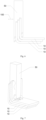
- the terminal fixing portion 40 has a bending extension portion 41 disposed in a plane or a non-plane with a bending angle of 0° to 180°, so as to adapt to different wiring directions.
- the terminal fixing portion 40 includes a body portion and a bending extension portion 41, and the terminal fixing portion 40 may be punched or cut to form a plurality of angles between the body portion and the bending extension portion 41.
- the bending extension portion 41 and the body portion are in the same plane, and the bending angle between their extending directions is exemplarily 90°.
- the bending extension portion 41 and the body portion are not in the same plane, and the bending extension portion 41 is bent and extended in a non-plane, and the bending angle between their extension directions is exemplarily 90°.
- the material of the terminal lamination 10 includes tellurium, and the body material of the terminal lamination 10 is tellurium-copper alloy, so that the terminal has a good electrical conductivity and machinability, thus ensuring the electrical performance and also improving the processability.
- the content of tellurium in the material of the terminal lamination 10 is 0.1% to 5% to ensure the electrical conductivity, and the elasticity of the tellurium copper alloy is also excellent.
- the content of tellurium in the tellurium copper alloy is 0.2% to 1.2%.
- the inventor selects ten terminal laminations 10 with the same shape and the same size for testing, and the number of the terminal laminations 10 in the plug-in terminals are equal.
- the body material of each of the terminal laminations 10 is the copper telluride alloy, in which the tellurium content of tellurium accounts for 0.05%, 0.1%, 0.2%, 0.5%, 0.8%, 1.2%, 2%, 3%, 5%, 6% and 7%, respectively.
- the electrical conductivity greater than 99% is an ideal value.
- Table 2 Influences of Tellurium Copper Alloys with Different Tellurium Contents on the Electrical Conductivity Tellurium content (%) 0.05 0.1 0.2 0.5 0.8 1.2 2 3 5 6 7 Electrical conductivity (%) 98.3 99.2 99.7 99.8 99.8 99.7 99.6 99.5 99.4 98.9 98.5
- the tellurium content is less than 0.1% or greater than 5%, the electrical conductivity decreases obviously, which cannot meet the requirements of the ideal value.
- the tellurium content is greater than or equal to 0.2% and less than or equal to 1.2%, the electrical conduction performance is the best.
- the tellurium content is greater than 1.2% and less than or equal to 5%, although the electrical conductivity meets the requirements of the ideal value, the trend is to gradually decrease and the electrical conduction performance will also decrease. Therefore, the inventor selects the tellurium copper alloy with a tellurium content of 0.1% to 5%. In the most ideal case, the tellurium copper alloy with a tellurium content of 0.2% to 1.2% is selected.
- the body material of the terminal lamination 10 includes beryllium.
- the material of the terminal lamination 10 is beryllium copper alloy, so that the terminal lamination 10 has high hardness, elastic limit, fatigue limit and wear resistance, and also has a good corrosion resistance, thermal conductivity and electrical conductivity, and does not generate sparks when being impacted.
- the content of beryllium in the body material of a micro-vibration terminal is 0.05% to 5%.
- the content of beryllium in the body material of a micro-vibration terminal is 0.1% to 3.5%.
- the inventor selects 10 terminal laminations 10 with the same shape and the same expansion joint width for testing, and each of the terminals includes beryllium, and the beryllium content accounts for 0.03%, 0.05%, 0.1%, 0.2%, 1%, 1.2%, 1.8%, 3%, 3.5%, 5% and 6% respectively.
- the test results are shown in Table 3.
- the inventor selects the terminal lamination 10 with a beryllium content of 0.05% to 5%.
- the terminal lamination 10 with a beryllium content of 0.1% to 3.5% is selected in the most ideal case.
- At least part of the surface of the terminal lamination 10 is provided with a plating layer, so as to increase the corrosion resistance, the electrical conductivity and the number of times of plugging, thereby better prolonging the service life of the plug-in structure.
- the surface of the conductive contact portion 31 is provided with the plating, and the plating layer on a surface of the conductive contact portion is a first plating layer.
- a surface of the scraping portion 32 is provided with the plating layer, and the plating layer on the surface of the scraping portion is a second plating layer.
- a surface of the connection arm 20 exclusive of the conductive contact portion 31 and the scraping portion 32 is provided with the plating layer, and the plating layer on the surface of the connection arm exclusive of the conductive contact portion and the scraping portion is a third plating layer.
- a surface of the terminal fixing portion 40 is provided with the plating layer, and the plating layer on the surface of the terminal fixing portion is a fourth plating layer.
- materials of the first plating layer, the second plating layer, the third plating layer and the fourth plating layer are different, i.e., the material of at least one of the first plating layer, the second plating layer, the third plating layer and the fourth plating layer is different from the others, and it may be the following situations:
- thicknesses of the first plating layer, the second plating layer, the third plating layer and the fourth plating layer are different, i.e., the thickness of at least one of the first plating layer, the second plating layer, the third plating layer and the fourth plating layer is different from the others, and it may be the following situations:
- the material of the third plating layer is the same as that of the fourth plating layer, and the material of the first plating layer or the second plating layer is different from that of the third plating layer, i.e., the material of the first plating layer is different from that of the third plating layer, or the material of the second plating layer is different from that of the third plating layer.
- the thickness of the third plating layer is the same as that of the fourth plating layer, and the thickness of the first plating layer or the second plating layer is different from that of the third plating layer, i.e., the thickness of the first plating layer is different from that of the third plating layer, or the thickness of the second plating layer is different from that of the third plating layer.
- plating layers of different metal materials have different electrical conduction effects and corrosion resistances.
- a plating layer of a metal material with a high price achieves a better electrical conduction effect and corrosion resistance, and is capable of being subjected to plugging and unplugging for more times and used in a more complex environment to obtain a longer service life.
- the high price limits the use of such plating layer.
- the inventor uses a metal material such as gold, silver, silver-antimony alloy, graphite silver, graphene silver, palladium-nickel alloy, tin-lead alloy or silver-gold-zirconium alloy, which has excellent properties but a high price, as the material of the plating layer at a position subjected to frequent plugging and unplugging or exposed in the use environment, and instead, selects a material with a low price as the material of the plating layer at a position subjected to infrequent plugging and infrequent unplugging or unlike to be exposed.
- a metal material such as gold, silver, silver-antimony alloy, graphite silver, graphene silver, palladium-nickel alloy, tin-lead alloy or silver-gold-zirconium alloy, which has excellent properties but a high price, as the material of the plating layer at a position subjected to frequent plugging and unplugging or exposed in the use environment, and instead, selects a material with a low price as the
- the conductive contact portion 31 is provided with a metal having a good electrical conduction effect and corrosion resistance but a high price as the material of the plating layer
- the terminal fixing portion 40 is provided with a material having a low price as the material of the plating layer.
- the inventor disposes thicker plating layers at these positions (e.g., the conductive contact portion 31 and the scraping portion 32) to improve the scrape resistance and the corrosion resistance of the plug-in terminal. Meanwhile, as other areas (e.g., the terminal fixing portion 40) are not scraped or exposed to the use environment, thinner plating layers may be used to reduce the cost.
- the plating layer may be disposed on the terminal lamination 10 by electroplating, chemical plating, magnetron sputtering, vacuum plating or the like.
- the electroplating is a process of plating a thin layer of other metal or alloy on a metal surface by using a principle of electrolysis.
- the chemical plating is a deposition process in which a metal is produced through a controllable oxidation-reduction reaction under a metal catalytic action.
- the magnetron sputtering is to use an interaction of a magnetic field and an electric field to make electrons move spirally near a target surface, thereby increasing the probability that electrons bombard argon to generate ions, and the generated ions bombard the target surface under the action of the electric field so as to sputter a target material.
- the vacuum plating is to deposit various metal films and non-metal films on the surface of parts by means of distillation or sputtering under vacuum conditions.
- the material of the plating layer includes one or more selected from gold, silver, nickel, tin, zinc, tin-lead alloy, silver-antimony alloy, palladium, palladium-nickel alloy, graphite silver, graphene silver and silver-gold-zirconium alloy.
- an active metal copper will react with oxygen and water during use, so one or more inactive metals are needed as the plating layer to prolong the service life of the plug-in terminal.
- a metal with good wear resistance is also needed as the plating layer, thereby greatly prolonging the service life of the contact point.
- the contact point requires a good electrical conduction performance, and the above metals have a better electrical conductivity and stability than copper or copper alloy, so that the plug-in terminal can obtain a better electrical performance and a longer service life.
- the inventor adopts plug-in terminal samples of the same specification, the same material, and having plating layers of different materials, to carry out a series of tests on the number of times of plugging and unplugging and the corrosion resistance time by using aluminum busbar of the same specification.
- the inventor also selects tin, nickel and zinc as the materials of the plating layers for experiment. The experimental results are shown in Table 4.
- the number of times of plugging and unplugging in Table 4 is obtained as follows: the plug-in terminals are fixed on an experimental platform respectively; a mechanical device is used to simulate the plugging and unplugging of the aluminum busbar; after every 100 times of plugging and unplugging, it is necessary to stop and observe the damage of the plating layer on the surface of each plug-in terminal; if the plating layer on the surface of the terminal is scraped and the material of the terminal itself is exposed, the experiment is stopped, and then the number of times of plugging and unplugging at that time is recorded. In this embodiment, when the number of times of plugging and unplugging is less than 8000, it is considered as unqualified.
- the test on the corrosion resistance time in Table 4 is to put a plug-in terminal into a salt spray test chamber, spray salt fog for each position on the plug-in terminal, take out and clean the plug-in terminal every 20 hours to observe corrosion on the surface, which is a cycle, stop the test when a corrosion area of the surface of the plug-in terminal is more than 10% of a total area thereof, and then record the number of cycles at that time. In this embodiment, when the number of cycles is less than 80, it is considered as unqualified.
- the inventor selects that the material of the plating layer includes one or more selected from gold, silver, nickel, tin, zinc, tin-lead alloy, silver-antimony alloy, palladium, palladium-nickel alloy, graphite silver, graphene silver and silver-gold-zirconium alloy.
- Table 4 Influences of Different Materials of Plating Layer on the Number of Times of Plugging and Unplugging and Corrosion Resistance of Terminals Different materials of plating layer Gold Silver Silver-antimony alloy Graphite silver Graphene silver Silver-gold-zirconium alloy Tin Nickel Palladium Palladium-nickel alloy Tin-lead alloy Zinc Number of times of plugging and unplugging 12400 11800 12200 12000 12700 12100 8600 8400 12000 12000 11000 8600 Number of cycles of corrosion resistance tests 131 128 122 130 16 131 83 89 111 122 109 88
- the plating layer includes a bottom layer and a surface layer, and is formed by a multi-layer plating method.
- a bottom layer is firstly plated on the surface of the terminal lamination 10 to fill the cracks and holes on the surface, so that the surface of the terminal lamination 10 is smooth and free of cracks and holes, and then a surface layer is plated, so that the binding is firmer and smoother, and the plated surface is free of cracks and holes.
- the material of the bottom layer includes one or more selected from gold, silver, nickel, tin, tin-lead alloy and zinc; and the material of the surface layer includes one or more selected from gold, silver, nickel, tin, zinc, tin-lead alloy, silver-antimony alloy, palladium, palladium-nickel alloy, graphite silver, graphene silver and silver-gold-zirconium alloy.
- the bottom layer has a thickness of 0.01 ⁇ m to 12 ⁇ m, and exemplarily a thickness of 0.1 ⁇ m to 9 ⁇ m.
- the surface layer has a thickness of 0.5 ⁇ m to 50 ⁇ m, and exemplarily a thickness of 1 ⁇ m to 35 ⁇ m.
- plug-in terminals of the same specification the same material, having nickel-plated bottom layers of different thicknesses, and having silver-plated surface layers of a same thickness, to carry out a series of tests on the temperature rise and the corrosion resistance time by using the mating plug-in terminals 50 of the same specification.
- the experimental results are shown in Table 5 below.
- the test on the temperature rise in Table 5 is to conduct the same current to the plug-in structures, detect the temperatures of the plug-in terminal at the same position before the current conduction and after the temperature is stable in a closed environment, and take a difference therebetween to obtain an absolute value. In this embodiment, when the temperature rise is greater than 50K, it is considered as unqualified.
- the test on the corrosion resistance time in Table 5 is to put a plug-in terminal into a salt spray test chamber, spray salt fog for each position on the plug-in terminal, take out and clean the plug-in terminal every 20 hours to observe corrosion on the surface, which is a cycle, stop the test when a corrosion area of the surface of the plug-in terminal is more than 10% of a total area thereof, and then record the number of cycles at that time. In this embodiment, when the number of cycles is less than 80, it is considered as unqualified.
- the thickness of the nickel-plated bottom layer is greater than 12 ⁇ m, the heat generated by the plug-in structure cannot be radiated since the bottom layer is thick, which makes the temperature rise of the plug-in structure unqualified, and the plating layer with the thick bottom layer is easy to fall off the surface of the terminal lamination 10, resulting in a decrease in the number of cycles of the corrosion resistance.
- the inventor selects the thickness of the bottom layer to be 0.01 ⁇ m to 12 ⁇ m.
- the inventor finds that the comprehensive effect of the temperature rise and the corrosion resistance of the plug-in structure is better when the thickness of the bottom layer of the plating layer is 0.1 ⁇ m to 9 ⁇ m. Therefore, in order to further improve the safety, reliability and practicability of the product itself, it is exemplarily that the thickness of the bottom layer of the plating layer is 0.1 ⁇ m to 9 ⁇ m.
- the inventor adopts plug-in terminal samples of the same specification, the same material, having nickel-plated bottom layers of the same thickness, and having silver-plated surface layers of different thicknesses, to carry out a series of tests on the temperature rise and the corrosion resistance time by using the mating plug-in terminals of the same specification.
- the experimental method is the same as that described above, and the experimental results are shown in Table 6 below.
- the temperature rise of the plug-in structure is qualified when the thickness of the silver-plated surface layer is less than 0.5 ⁇ m, the number of cycles of corrosion resistance of the plug-in terminal is less than 80 since the surface layer is too thin, and the performance requirement of the plug-in terminal cannot be met, which greatly affects the overall performance and the service life of the plug-in structure, and in severe cases, causes the product service life to be reduced sharply or even a failure leading to burning accidents.
- the thickness of the silver-plated surface layer is greater than 50 ⁇ m, the heat generated by the plug-in terminal cannot be radiated since the surface layer is thick, which makes the temperature rise unqualified, and the plating layer with the thick surface layer is easy to fall off the surface of the terminal, resulting in a decrease in the number of cycles of the corrosion resistance tests. Moreover, since the surface layer is made of precious metal, the plating layer with the thick surface layer does not improve the performance and has no use value. Thus, the inventor selects the thickness of the silver-plated surface layer to be 0.1 ⁇ m to 50 ⁇ m. Exemplarily, the inventor finds that the comprehensive effect of the temperature rise and the corrosion resistance of the terminal is better when the thickness of the surface layer of the plating layer is 1 ⁇ m to 35 ⁇ m. Therefore, in order to further improve the safety, reliability and practicability of the product itself, it is exemplary that the thickness of the surface layer of the plating layer is 1 ⁇ m to 35 ⁇ m.
- the material of the plating layer on the overhanging end 21 is different from that of the plating layer on the fixed end 22.
- the plating layers of different metal materials achieve different electrical conduction effects and corrosion resistances.
- a plating layer of a metal material with a high price achieves a better electrical conduction effect and corrosion resistance, and is capable of being subjected to plugging and unplugging for more times and used in a more complex environment to obtain a longer service life.
- the high price limits the use of such plating layer.
- the inventor uses a metal material such as gold, silver, silver-antimony alloy, graphite silver, graphene silver, palladium-nickel alloy, tin-lead alloy and silver-gold-zirconium alloy, which has excellent properties but a high price, as the material of the plating layer at a position subjected to frequent plugging and unplugging or exposed in the use environment.
- a metal material such as gold, silver, silver-antimony alloy, graphite silver, graphene silver, palladium-nickel alloy, tin-lead alloy and silver-gold-zirconium alloy, which has excellent properties but a high price, as the material of the plating layer at a position subjected to frequent plugging and unplugging or exposed in the use environment.
- the fixed end 22 is at the position where the wires are connected, and there is substantially no relative displacement after being connected to the wires, and the fixed end 22 is generally protected in a molded housing and will not be exposed to the use environment, so the inventor uses the conventional metal such as tin, nickel or zinc as the material of the plating layer of the fixed end 22 to reduce the cost of the connection structure.
- a ratio of a minimum width of the connection arm 20 to a thickness thereof is 0.5 to 10.
- the terminal lamination 10 is capable of being plugged with the mating plug-in terminal 50 only when the terminal lamination 10 is elastic, and there is a practical use value only when the ratio of the width of the connection arm 20 of the terminal lamination 10 to the thickness thereof does not exceed a certain range.
- the ratio is too large, i.e., the thickness is too small, the overall strength of the terminal lamination 10 is too small, and more terminal laminations 10 are required to meet the actual needs, which means that more working time is required; and when the ratio is too large, i.e., the thickness is too large, the terminal lamination 10 will not be easily deformed, which affects the plugging with the mating plug-in terminal 50.
- the inventor conducts tests in the following method: the inventor selects the same mating plug-in terminal 50 and different terminal laminations 10, in which the terminal laminations 10 have the connection arms 20 with the same width and different thicknesses, and different terminal laminations 10 are used for plugging test with the mating plug-in terminal 50. If the connection arm 20 is too thick to realize plugging, or the connection arm 20 is too thin and leads to an irreversible deformation, it is considered as unqualified and otherwise qualified. The results are shown in Table 7.
- connection arm 20 when the ratio of the minimum width of the connection arm 20 to the thickness thereof is less than 0.5, the connection arm 20 will be deformed during plugging, resulting in the abandonment of the terminal lamination 10; and when the ratio of the minimum width of the connection arm 20 to the thickness of the connection arm 20 is greater than 10, it is impossible for plugging, so the inventor selects that the ratio of the minimum width of the connection arm 20 to the thickness thereof is 0.5 to 10.
- Table 7 Influences of Different Ratios of Minimum Width Connection Arm to Thickness thereof on Terminal Plugging Ratio of Minimum Width Connection Arm to Thickness thereof 0.1 0.3 0.5 1 3 5 7 10 11 12 Whether plugging can be made Yes Yes Yes Yes Yes Yes Yes Yes Yes No No No Whether deformation occurs Yes Yes No No No No No No No No No No No No No No No No No No No No No No No No No No No No No No No No
- the gap between the connection arms of adjacent two of the terminal laminations 10 is less than 0.2 mm.
- One purpose of providing the gap between terminal laminations 10 is to make air circulate between the adjacent connection arms 20, so as to reduce the temperature rise between the mating plug-in terminal 50 and the plug-in terminal, protect the plating layer and prolong the service life of the plug-in structure.
- Another purpose is to release the elasticity of the connection arms 20 themselves, and ensure the clamping force between the opposite connection arms 20, thereby ensuring the plugging force.
- connection arm 20 with the same contact area occupy a larger width and waste the use space.
- the connection arm 20 with the same contact area will consume more volume of the mating plug-in terminal 50, thereby increasing the consumption of the terminal and the cost of the plug-in structure.
- connection arm 20 is made of a memory alloy.
- the memory alloy is an intelligent metal with a memory ability, and its microstructure has two relatively stable states; the memory alloy may be changed into any desired shape at a high temperature and may be stretched at a low temperature; when being reheated, the memory alloy will remember its original shape and change back; the memory alloy have different crystal structures above its transition temperature and below its transition temperature, and when the temperature changes around the transition temperature, the memory alloy will contract or expand, thereby causing a change of its morphology.
- the transition temperature of the memory alloy is 40°C to 70 °C.
- the temperature of the connection arms 20 is lower than the transition temperature, a plurality of connection arms 20 are in an expanded state; and when the temperature of the connection arm 20 is higher than the transition temperature, a plurality of connection arms are in a clamped state.
- the transition temperature is selected from 40°C to 70°C, because if the transition temperature is lower than 40°C, the ambient temperature of the plug-in terminal will be close to 40°C without current conduction.
- the plurality of connection arms 20 is in a clamped state, the plugging groove of the plug-in terminal is narrowed, and the aluminum busbar cannot be plugged thereinto, so that the aluminum busbar cannot be plugged with the plug-in structure of the terminal, and the working cannot be carried out.
- the transition temperature of the memory alloy is set to be 40°C to 70°C.
- the present invention further provides a plug-in structure, including the aforementioned plug-in terminal and a mating plug-in terminal 50 plugged therewith.
- a plugging force between the plug-in terminal and the mating plug-in terminal 50 is 3 N to 150 N.
- a plugging force between the plug-in terminal and the mating plug-in terminal 50 is 10 N to 95 N.
- the inventor selects the plug-in terminal and the mating plug-in terminal 50 which have the same shape and the same size, and designs different plugging force between the plug-in terminal and the mating plug-in terminal 50 to observe the contact resistance therebetween and the situation after multiple plugging.
- the detection method of the contact resistance is to use a micro-resistance measurement instrument to measure the resistance at a position where the plug-in terminal and the mating plug-in terminal 50 are contacted, and read the value on the micro-resistance measurement instrument.
- the contact resistance less than 50 ⁇ is an ideal value.
- the test method of the plugging situation of the plug-in terminal and mating plug-in terminal 50 is to perform 50 times of plugging between the plug-in terminal and the mating plug-in terminal 50, and observe the number of times of drops after plugging and unplugging and the number of times of incapability of plugging and unplugging.
- the number of times of drops after plugging and unplugging should be less than 3, and the number of times of incapability of plugging and unplugging should be less than 5.
- the plugging force between the plug-in terminal and the mating plug-in terminal 50 is less than 3 N, the contact resistance therebetween is higher than an ideal value because the bonding force is too small. Meanwhile, the number of drops after plugging and unplugging is more than 3, which is unqualified.
- the plugging force between the plug-in terminal and the mating plug-in terminal 50 is greater than 150 N, the number of times of incapability of plugging and unplugging therebetween is more than 5, which is also unqualified. Therefore, the inventor sets the plugging force between the plug-in terminal and the mating plug-in terminal 50 to be 3 N to 150 N.
- the inventor exemplarily sets the plugging force between the plug-in terminal and the mating plug-in terminal 50 to be 10 N to 95 N.
- the contact resistance between the plug-in terminal and the mating plug-in terminal 50 is less than 9 mS2. Generally, it is necessary to conduct a large current. If the contact resistance between the plug-in terminal and the mating plug-in terminal 50 is greater than 9 mQ, a large temperature rise occurs at the contact position, and the temperature becomes increasingly higher as time elapses. Since the plug-in terminal and the mating plug-in terminal 50 have different coefficients of thermal expansion due to different materials thereof, their mechanical deformations are unsynchronized that leads to an internal stress, and in severe cases, the plating layer will fall off and cannot realize the protection.
- the excessive temperature of the plug-in terminal and the mating plug-in terminal 50 may be conducted to an insulation layer of the wire connected thereto, so that the insulation layer is melt and cannot realize insulation protection, and in severe cases, a short circuit may be caused, resulting in a damage to the connection structure and even safety accidents such as burning. Therefore, the inventor sets the contact resistance between the plug-in terminal and the mating plug-in terminal 50 to be less than 9 mS2.
- the inventor selects the same mating plug-in terminal 50, and plug-in terminals with different contact resistances, to test the electrical conductivity and the temperature rise.
- the test on the electrical conductivity is to detect the electrical conductivity at a corresponding plugging position after the mating plug-in terminal 50 and the plug-in terminal are plugged together and the plug-in structure is electrified.
- the electrical conductivity greater than 99% is an ideal value.
- the test on the temperature rise is to conduct the same current to the plug-in structure, detect the temperatures of the plug-in terminal at the same position before the current conduction and after the temperature is stable in a closed environment, and take a difference therebetween to obtain an absolute value.
- the temperature rise is greater than 50K, it is considered as unqualified.
- the inventor sets the contact resistance between the plug-in terminal and the mating plug-in terminal 50 to be less than 9 mS2.
- the present disclosure further provides a motor vehicle, including the aforementioned plug-in terminal.
- the present disclosure further provides a motor vehicle, including the aforementioned plug-in structure.
Landscapes
- Connections Effected By Soldering, Adhesion, Or Permanent Deformation (AREA)
- Motor Or Generator Frames (AREA)
- Connector Housings Or Holding Contact Members (AREA)
Applications Claiming Priority (2)
| Application Number | Priority Date | Filing Date | Title |
|---|---|---|---|
| CN202110944154.6A CN113571934A (zh) | 2021-08-17 | 2021-08-17 | 插接端子、插接结构及机动车辆 |
| PCT/CN2022/110786 WO2023020312A1 (fr) | 2021-08-17 | 2022-08-08 | Borne de prise, structure de prise et véhicule à moteur |
Publications (2)
| Publication Number | Publication Date |
|---|---|
| EP4391238A1 true EP4391238A1 (fr) | 2024-06-26 |
| EP4391238A4 EP4391238A4 (fr) | 2025-01-15 |
Family
ID=78171925
Family Applications (1)
| Application Number | Title | Priority Date | Filing Date |
|---|---|---|---|
| EP22857624.5A Pending EP4391238A4 (fr) | 2021-08-17 | 2022-08-08 | Borne de prise, structure de prise et véhicule à moteur |
Country Status (7)
| Country | Link |
|---|---|
| US (1) | US20250286298A1 (fr) |
| EP (1) | EP4391238A4 (fr) |
| JP (1) | JP2024532838A (fr) |
| CN (1) | CN113571934A (fr) |
| MX (1) | MX2024002030A (fr) |
| WO (1) | WO2023020312A1 (fr) |
| ZA (1) | ZA202401717B (fr) |
Families Citing this family (3)
| Publication number | Priority date | Publication date | Assignee | Title |
|---|---|---|---|---|
| CN113571934A (zh) * | 2021-08-17 | 2021-10-29 | 长春捷翼汽车零部件有限公司 | 插接端子、插接结构及机动车辆 |
| CN119864264B (zh) * | 2025-03-24 | 2025-05-30 | 杭州精晟新能源科技有限公司 | 一种熔断元件及熔断器 |
| CN119864265B (zh) * | 2025-03-25 | 2025-05-30 | 杭州精晟新能源科技有限公司 | 一种高稳定熔断器 |
Family Cites Families (31)
| Publication number | Priority date | Publication date | Assignee | Title |
|---|---|---|---|---|
| US5004426A (en) * | 1989-09-19 | 1991-04-02 | Teradyne, Inc. | Electrically connecting |
| US5217382A (en) * | 1992-06-05 | 1993-06-08 | Interlock Corporation | Electric receptacle with shape memory spring member |
| GB9324762D0 (en) * | 1993-12-02 | 1994-01-19 | Amp Holland | Low insertion force receptacle terminal |
| JPH11185827A (ja) * | 1997-12-22 | 1999-07-09 | Toshiba Corp | 電子機器の端子構造 |
| FR2809544B1 (fr) * | 2000-05-24 | 2002-07-26 | Fci Pontarlier | Dispositif de contacts multiples pour les systemes de barres de bus de puissance |
| DE10352761B4 (de) * | 2003-11-12 | 2006-06-08 | Wolf Neumann-Henneberg | Anschlusskontakt zur elektrischen Kontaktierung einer Leiterplatte oder eines Stanzgitters |
| JP2005294220A (ja) * | 2004-04-05 | 2005-10-20 | Yamaichi Electronics Co Ltd | 大電流用雌側コネクタ |
| DE102004021529B4 (de) * | 2004-05-03 | 2007-02-01 | Lumberg Connect Gmbh & Co. Kg | Kontaktvorrichtung |
| DE102007029968A1 (de) * | 2007-06-28 | 2009-01-08 | Robert Bosch Gmbh | Elektrischer Steckverbinder als Kraftstoffinjektor-Kontakt für schüttelfeste Anwendungen |
| JP5053338B2 (ja) * | 2009-07-23 | 2012-10-17 | 京セラコネクタプロダクツ株式会社 | コンタクト、及び、コネクタ |
| US8914183B2 (en) * | 2010-09-20 | 2014-12-16 | Joshua Forwerck | Enhanced electronic assembly |
| JP5138827B1 (ja) * | 2012-03-23 | 2013-02-06 | Jx日鉱日石金属株式会社 | 電子部品用金属材料、それを用いたコネクタ端子、コネクタ及び電子部品 |
| DE102013013458B3 (de) * | 2013-08-14 | 2014-10-30 | Lisa Dräxlmaier GmbH | Kontaktelement |
| JP6004121B2 (ja) * | 2013-12-04 | 2016-10-05 | 株式会社オートネットワーク技術研究所 | 電気接点およびコネクタ端子対 |
| JP2015116065A (ja) * | 2013-12-12 | 2015-06-22 | アスモ株式会社 | 回路装置付きモータ |
| CN205178083U (zh) * | 2015-11-10 | 2016-04-20 | 连展科技(深圳)有限公司 | 插头端子 |
| CN205194972U (zh) * | 2015-12-02 | 2016-04-27 | 河南天海电器有限公司 | 具有反向自锁结构的汽车插接器 |
| JP6765243B2 (ja) * | 2016-07-14 | 2020-10-07 | ヒロセ電機株式会社 | 電気コネクタ |
| JP2018156771A (ja) * | 2017-03-16 | 2018-10-04 | 住友電装株式会社 | 雌端子 |
| US10476191B2 (en) * | 2018-02-28 | 2019-11-12 | Ohio Associated Enterprises, Llc | Forked electrical contact pair with elastic tail |
| DE102018213688A1 (de) * | 2018-08-14 | 2020-02-20 | Te Connectivity Germany Gmbh | Kontaktelement, Stecker mit einem Kontaktelement und Kontaktanordnung zur Kontaktierung eines Bipolarstapels |
| CN210692819U (zh) * | 2019-10-30 | 2020-06-05 | 观致汽车有限公司 | 电源端子及包含其的保险丝盒 |
| CN212874836U (zh) * | 2020-08-24 | 2021-04-02 | 乐清市八达光电科技股份有限公司 | 一种双向堆叠式大电流插接端子及具有其的连接器 |
| CN112072356A (zh) * | 2020-08-24 | 2020-12-11 | 乐清市八达光电科技股份有限公司 | 一种双向堆叠式大电流插接端子及具有其的连接器 |
| CN112670763A (zh) * | 2020-11-30 | 2021-04-16 | 南京康尼新能源汽车零部件有限公司 | 一种可浮动自适应大功率接触端子模块 |
| CN113571934A (zh) * | 2021-08-17 | 2021-10-29 | 长春捷翼汽车零部件有限公司 | 插接端子、插接结构及机动车辆 |
| CN215816489U (zh) * | 2021-08-17 | 2022-02-11 | 长春捷翼汽车零部件有限公司 | 插接端子、插接结构及机动车辆 |
| CN113571943A (zh) * | 2021-08-17 | 2021-10-29 | 长春捷翼汽车零部件有限公司 | 扁带与端子的插接结构及机动车辆 |
| CN217215197U (zh) * | 2021-10-01 | 2022-08-16 | 长春捷翼汽车零部件有限公司 | 一种高压连接机构、电能传输装置及机动车辆 |
| CN113922123B (zh) * | 2021-10-01 | 2026-01-16 | 长春捷翼汽车科技股份有限公司 | 一种高压连接机构、电能传输装置及机动车辆 |
| CN217215185U (zh) * | 2021-12-23 | 2022-08-16 | 长春捷翼汽车零部件有限公司 | 一种插接端子及插接端子安装结构 |
-
2021
- 2021-08-17 CN CN202110944154.6A patent/CN113571934A/zh active Pending
-
2022
- 2022-08-08 JP JP2024509438A patent/JP2024532838A/ja active Pending
- 2022-08-08 MX MX2024002030A patent/MX2024002030A/es unknown
- 2022-08-08 WO PCT/CN2022/110786 patent/WO2023020312A1/fr not_active Ceased
- 2022-08-08 EP EP22857624.5A patent/EP4391238A4/fr active Pending
- 2022-08-08 US US18/684,169 patent/US20250286298A1/en active Pending
-
2024
- 2024-02-28 ZA ZA2024/01717A patent/ZA202401717B/en unknown
Also Published As
| Publication number | Publication date |
|---|---|
| ZA202401717B (en) | 2024-10-30 |
| US20250286298A1 (en) | 2025-09-11 |
| MX2024002030A (es) | 2024-03-06 |
| WO2023020312A1 (fr) | 2023-02-23 |
| CN113571934A (zh) | 2021-10-29 |
| EP4391238A4 (fr) | 2025-01-15 |
| JP2024532838A (ja) | 2024-09-10 |
Similar Documents
| Publication | Publication Date | Title |
|---|---|---|
| EP4391238A1 (fr) | Borne de prise, structure de prise et véhicule à moteur | |
| EP4391242A1 (fr) | Structure d'insertion de courroie plate et de borne, et véhicule à moteur | |
| WO2023024971A1 (fr) | Mécanisme de transfert pour transmission d'énergie, douille de charge et véhicule à moteur | |
| EP4383464A1 (fr) | Structure de connexion électrique, siège de charge et automobile | |
| EP4383465A1 (fr) | Structure de connexion électrique, douille de charge et automobile | |
| WO2024222715A1 (fr) | Borne multi-revêtement et structure conductrice | |
| JP5261278B2 (ja) | コネクタおよびコネクタ用金属材料 | |
| EP4443663B1 (fr) | Structure de lame métallique et connecteur électrique | |
| CN216698787U (zh) | 一种电连接结构、充电座以及汽车 | |
| US20240356274A1 (en) | Micro-vibration terminal, plug-in structure, and motor vehicle | |
| CN215732301U (zh) | 微振动端子、插接结构及机动车辆 | |
| CN109155208B (zh) | 电触点用的覆层材料和该覆层材料的制造方法 | |
| CN215816489U (zh) | 插接端子、插接结构及机动车辆 | |
| CN217691766U (zh) | 扁带与端子的插接结构及机动车辆 | |
| JP6592299B2 (ja) | ブレーカー及びそれを備えた安全回路並びに2次電池回路。 | |
| EP4411998A1 (fr) | Mécanisme de connexion de type à courroie plate, appareil de transmission d'énergie électrique et véhicule à moteur | |
| CN217215133U (zh) | 金属簧片结构及电连接器 | |
| EP4411997A1 (fr) | Mécanisme de connexion, dispositif de transmission d'énergie électrique et véhicule à moteur | |
| EP4372919A1 (fr) | Borne et son procédé de traitement | |
| US10361501B2 (en) | Ni-plated copper or copper alloy material, connector terminal, connector and electronic component using the same | |
| EP4372923B1 (fr) | Borne enfichable | |
| WO2023189751A1 (fr) | Module de connexion de borne et borne | |
| Holm | About stationary contacts in practice |
Legal Events
| Date | Code | Title | Description |
|---|---|---|---|
| STAA | Information on the status of an ep patent application or granted ep patent |
Free format text: STATUS: THE INTERNATIONAL PUBLICATION HAS BEEN MADE |
|
| PUAI | Public reference made under article 153(3) epc to a published international application that has entered the european phase |
Free format text: ORIGINAL CODE: 0009012 |
|
| STAA | Information on the status of an ep patent application or granted ep patent |
Free format text: STATUS: REQUEST FOR EXAMINATION WAS MADE |
|
| 17P | Request for examination filed |
Effective date: 20240306 |
|
| AK | Designated contracting states |
Kind code of ref document: A1 Designated state(s): AL AT BE BG CH CY CZ DE DK EE ES FI FR GB GR HR HU IE IS IT LI LT LU LV MC MK MT NL NO PL PT RO RS SE SI SK SM TR |
|
| P01 | Opt-out of the competence of the unified patent court (upc) registered |
Free format text: CASE NUMBER: APP_43250/2024 Effective date: 20240724 |
|
| DAV | Request for validation of the european patent (deleted) | ||
| DAX | Request for extension of the european patent (deleted) | ||
| REG | Reference to a national code |
Ref country code: DE Ref legal event code: R079 Free format text: PREVIOUS MAIN CLASS: H01R0013020000 Ipc: H01R0013110000 |
|
| A4 | Supplementary search report drawn up and despatched |
Effective date: 20241218 |
|
| RIC1 | Information provided on ipc code assigned before grant |
Ipc: H01R 13/03 20060101ALN20241212BHEP Ipc: H01R 13/11 20060101AFI20241212BHEP |