EP4373748B1 - Système d'arrêt en matériau d'ingénierie - Google Patents
Système d'arrêt en matériau d'ingénierie Download PDFInfo
- Publication number
- EP4373748B1 EP4373748B1 EP22730447.4A EP22730447A EP4373748B1 EP 4373748 B1 EP4373748 B1 EP 4373748B1 EP 22730447 A EP22730447 A EP 22730447A EP 4373748 B1 EP4373748 B1 EP 4373748B1
- Authority
- EP
- European Patent Office
- Prior art keywords
- bed
- arrestor
- blocks
- stratified
- compressive strength
- Prior art date
- Legal status (The legal status is an assumption and is not a legal conclusion. Google has not performed a legal analysis and makes no representation as to the accuracy of the status listed.)
- Active
Links
Images






Classifications
-
- B—PERFORMING OPERATIONS; TRANSPORTING
- B64—AIRCRAFT; AVIATION; COSMONAUTICS
- B64F—GROUND OR AIRCRAFT-CARRIER-DECK INSTALLATIONS SPECIALLY ADAPTED FOR USE IN CONNECTION WITH AIRCRAFT; DESIGNING, MANUFACTURING, ASSEMBLING, CLEANING, MAINTAINING OR REPAIRING AIRCRAFT, NOT OTHERWISE PROVIDED FOR; HANDLING, TRANSPORTING, TESTING OR INSPECTING AIRCRAFT COMPONENTS, NOT OTHERWISE PROVIDED FOR
- B64F1/00—Ground or aircraft-carrier-deck installations
- B64F1/02—Ground or aircraft-carrier-deck installations for arresting aircraft, e.g. nets or cables
- B64F1/025—Ground or aircraft-carrier-deck installations for arresting aircraft, e.g. nets or cables using decelerating or arresting beds
-
- E—FIXED CONSTRUCTIONS
- E01—CONSTRUCTION OF ROADS, RAILWAYS, OR BRIDGES
- E01C—CONSTRUCTION OF, OR SURFACES FOR, ROADS, SPORTS GROUNDS, OR THE LIKE; MACHINES OR AUXILIARY TOOLS FOR CONSTRUCTION OR REPAIR
- E01C5/00—Pavings made of prefabricated single units
- E01C5/06—Pavings made of prefabricated single units made of units with cement or like binders
- E01C5/065—Pavings made of prefabricated single units made of units with cement or like binders characterised by their structure or component materials, e.g. concrete layers of different structure, special additives
-
- E—FIXED CONSTRUCTIONS
- E01—CONSTRUCTION OF ROADS, RAILWAYS, OR BRIDGES
- E01C—CONSTRUCTION OF, OR SURFACES FOR, ROADS, SPORTS GROUNDS, OR THE LIKE; MACHINES OR AUXILIARY TOOLS FOR CONSTRUCTION OR REPAIR
- E01C9/00—Special pavings; Pavings for special parts of roads or airfields
- E01C9/007—Vehicle decelerating or arresting surfacings or surface arrangements, e.g. arrester beds ; Escape roads, e.g. for steep descents, for sharp bends
-
- E—FIXED CONSTRUCTIONS
- E01—CONSTRUCTION OF ROADS, RAILWAYS, OR BRIDGES
- E01F—ADDITIONAL WORK, SUCH AS EQUIPPING ROADS OR THE CONSTRUCTION OF PLATFORMS, HELICOPTER LANDING STAGES, SIGNS, SNOW FENCES, OR THE LIKE
- E01F13/00—Arrangements for obstructing or restricting traffic, e.g. gates, barricades ; Preventing passage of vehicles of selected category or dimensions
- E01F13/12—Arrangements for obstructing or restricting traffic, e.g. gates, barricades ; Preventing passage of vehicles of selected category or dimensions for forcibly arresting or disabling vehicles, e.g. spiked mats
Definitions
- This invention relates to Engineered Material Arresting Systems (EMAS) beds for decelerating and steering vehicles/aircrafts unable to stop on their own. More precisely, the invention relates to EMAS-beds having a course directing effect on vehicles entering the bed.
- EMAS Engineered Material Arresting Systems
- a runway overrun is a landing accident with potentially fatal consequences caused by an aircraft being unable to stop before it reaches the end of the runway.
- Typical causes for runway overruns are pilot errors, poor weather, and/or a technical fault with the aircraft.
- EMAS Engineered Materials Arresting Systems
- EMAS design typically involves optimizing the bed geometry to provide the best overall fleet performance. Fleet optimization requires compromises and results in sub-optimal performance for some of the aircraft. Shallow beds and softer materials improve the arresting performance for smaller aircraft, but large aircraft require the opposite traits. Consequently, there is significant motivation to develop EMAS concepts that can improve the performance for mixed fleets of large and small aircraft. Because most airports serve a wide range of aircraft, EMAS should advantageously be designed to stop planes of very different sizes, ranging from as little as 12 metric tons up to 450 metric tons. Aircraft may have very different tire sizes, ranging from less than 50 cm to above 145 cm in diameter. EMAS are specifically designed for the typical fleet of aircraft serviced by a particular airport, and they are tailored to the available space beyond the end of the runway.
- EMAS typically consist of large shallow beds of absorbent material that engage an aircraft's tires and absorbs the aircraft's kinetic energy to bring it to a controlled stop.
- Commercially available EMAS use different types of construction, but the principal absorbing materials are typically cementitious foam block or glass foam aggregate.
- US 3,967,704 describes a safety device for quickly arresting the movement of vehicles such as aeroplanes and motor cars by forming a retarding bed of crushable material adjacent to a vehicle track.
- a foam is formed from an amino plastic resin composition and laid down in a bed adjacent to the vehicle track where it is cured in situ to produce a non-resilient cured foam body having a compressive strength between 15 and 50 p.s.i. (0.10 to 0.34 MPa) and a density from 0.25 to 10 pounds per cubic foot (4 to 160 kg/m 3 ).
- the document describes an example embodiment of the bed having uniform thickness in a central position and sloping sides to provide a centralising effect on aircraft using it.
- US 5,885,025 describes vehicle arresting assembled of a large number of blocks of cellular concrete having predetermined compressive gradient strength, so that aircraft landing gear is subjected to drag forces effective to slow a variety of types of aircraft, while providing deceleration within a safe range of values.
- An arresting bed typically includes an entry region of a depth increasing from 9 to 24 inches (23 to 61 cm) formed of blocks having a first compressive gradient strength.
- a second region which may be tapered into the first region and increase in depth to 30 inches (76) cm, is formed of blocks having a greater compressive gradient strength.
- a protective hard coat layer of cellular concrete of strength greater than the blocks overlays the blocks to enable service personnel to walk on the bed without damage.
- Arresting bed systems may be provided in alternative configurations, such as a bed formed of an aggregate including pieces of cellular concrete with or without interspersed pieces of other compressible material and covered by a hard coat layer.
- the document discloses further an example embodiment having blocks cellular cement in a first lateral row with a lower compressive gradient strength than blocks in the following lateral rows to increase the retardation effect on the aircraft in longitudinal direction.
- US 10,458,073 B2 discloses systems and methods for arresting aircraft.
- the systems and methods can be useful in arresting light aircraft because they typically do not have the weight to penetrate available EMAS systems.
- the system is generally provided as a structure having a suspended layer of energy absorbing material.
- a lower portion of the system can have a lower strength, used as a method to suspend an upper, stronger/more highly energy absorbent portion of the system.
- ACRP Report 29 also describes a prefabricated block having a depth-varying by multiple layers of compactible foam material having different compressive strengths are glued together such that softer layers would be placed near the surface of the bed, while firmer layers would be placed near the bottom. This concept was intended to help improve the performance of arrestor-beds with mixed aircraft fleets. Lighter aircraft would engage primarily with softer layers of compactible foam near the surface, while heavier aircraft would penetrate more deeply and engage with firmer layers of foam near the bottom. The report described modeling and simulation results that showed improved mixed fleet performance compared with EMAS that have a single strength of material throughout the thickness.
- the depth-varying concept was originally proposed in ACRP Report 29 as being comprised of multiple layers or strata of compactible foam adhered to another to achieve the full EMAS bed thickness.
- the layers at the bottom of the block would have the highest density and crush strength, while the layer at the top would have the lowest density and crush strength.
- the depth-varying properties of the bed would provide improved mixed-fleet arresting performance by allowing light aircraft to engage the soft upper layers, while heavy aircraft would penetrate more deeply and engage the firmer lower layers of material.
- Aircraft overruns are emergency situations in which one or more things have gone wrong.
- aircraft often do not exit along the centerline of the runway, but instead may be offset to the left or right.
- Aircraft also may not travel in a parallel direction to the runway, but instead may veer along a diagonal line of travel.
- the typical design of runways involves a shallow side slope to facilitate water drainage, which may increase veering behavior in some situations.
- aircraft veer diagonally it can result in the aircraft taking a shorter path through an EMAS arrestor-bed. This results in a premature exit along the lateral edge of the bed, thereby shortening the length of travel through the bed and reducing the protection the EMAS was designed to provide.
- EMAS presently have no design features to control the path of aircraft travel, and innovations that could provide a centering effect are desirable.
- US 5 193 764 A discloses a system for arresting movement of an aircraft travelling off the end of a runway at high speeds.
- a panel is formed by connecting rigid, friable, fire resistant foam boards, and a plurality of layers comprised of stacked panels are adhered to a base surface.
- the main objective of the invention is the provision of Engineered Material Arresting Systems (EMAS) beds for decelerating and steering vehicles/aircrafts unable to stop on their own.
- EANS Engineered Material Arresting Systems
- An arrestor-bed is a bed of a compactible foam material laid over a stretch of ground or felled into the ground like e.g. a basin filled with the compactible foam material.
- the arrestor-bed is in some embodiments laid at the end of a runway but may be laid/applied at any location where a vehicle/aircraft may be expected to become (involuntary) in need for external assistance to make a controlled stop.
- Arrestor-beds are typically either made of an aggregate of particulate compactible material filling a basin laid onto or in the soil/underground, or prefabricated blocks of compactible material assembled on site to form a bed on a soil/underground.
- the present invention relates to the latter, arrestor-beds made by assembling and adhering together the prefabricated blocks. The adhering of the prefabricated blocks to each other may be obtained by e.g. gluing, caulking, adhesive tape, etc.
- the present invention is based on the realisation that an observed weakness of the joints between the prefabricated blocks, which typically have a lower shear strength than the continuous areas of the prefabricated blocks, may be utilised to give the arrestor-bed a directional loading assisting in centralising the travel path of a vehicle passing through the arrestor-bed. I.e., by angling the orientation of the prefabricated blocks instead of arranging them in a right-angle grid typically of prior art, the retardation forces induced on the wheels of the vehicle will have a lateral component providing the effect of assisting the vehicle to travel along the longitudinal centre axis of the arrestor-bed.
- the invention relates to a vehicle arresting system comprising an arrestor-bed laid onto a base/ground and having longitudinal centre axis extending from a front end to a back end opposite the front end, wherein the arrestor-bed comprises:
- the term "longitudinal” as used herein refers to the direction at which a vehicle/- aircraft entering the arrestor-bed is expected to travel across the arrestor-bed.
- the term "front end” as used herein is the side at which the vehicle/aircraft is expected to enter the arrestor-bed/EMAS and the “back side” is the side opposite the front end.
- the arrestor-bed may in some embodiments be shaped into a longitudinal rectangular bed (as seen from above), i.e. having a relatively short width as compared to its length.
- arrestor-bed refers to a bed of a compactible foam material laid over a stretch of ground or felled into the ground like e.g. a basin filled with the compactible foam material.
- the arrestor-bed is in some embodiments laid at the end of a runway but may be laid/applied at any location where a vehicle/aircraft may be expected to become (involuntary) in need for external assistance to make a controlled stop.
- the arrestor-bed will hereafter is described in relation to airfields and the need for averting aircraft overrun accidents, the arrestor-bed according to the invention is not confined to aviation/airfields but may be applied for absorbing the kinetic energy and stop any wheeled vehicle crossing the arrestor-bed at any location wherever such functionality may be wanted.
- the arrestor-bed may in the literature also be denoted as an "Engineered Material Arresting System, EMAS.” These terms are used interchangeably herein.
- the invention according to the first aspect is not tied to any particular design, size or location, but encompasses any size and design of arrestor-beds known or conceivable to the person skilled in the art. Furthermore, the present invention is not reliant on how the arrestor-bed is made or assembled. Any known and conceivable way of forming a bed of prefabricated blocks of a compactible foam material on a location where an arrestor-bed is to be located is included in the present invention as long as the arrestor-bed has angled linear lines of prefabricated blocks forming a consecutive series of inverted V-patterns along the longitudinal centre axis relative to a direction from the front end to the back end of the arrestor-bed.
- compactible foam material encompasses any material known to the person skilled in the art for being suitable as a deformable/collapsible material that engages an incoming wheel of a vehicle/aircraft and absorbs kinetic energy from the vehicle/aircraft to bring it to a controlled stop.
- suited materials include, but is not limited to, cellular cement, cellular cementitious material, foam cement, polymeric foam, honeycomb, metal honeycomb, vermiculite, perlite, ceramic foams, foam glass and other isotropic or anisotropic compactible/- deformable materials, or combinations thereof.
- the compactible foam material of an arrestor-bed has a tailored mechanical strength such that the arrestor-bed is unable to carry the wheel(s) of a vehicle/aircraft entering the arrestor-bed, but sinks some distance into the compactible foam material such that the compactible foam material absorbs kinetic energy from the vehicle/aircraft and brings it to a forced stop, such as shown in the photograph of figure 1 .
- the compressive strength of compactible foam materials which provide an effective but controlled stopping action on vehicles/aircrafts depends heavily on the expected tire pressure pressing onto the surface of the arrestor-bed by the wheels of the vehicle/aircraft entering the arrestor bed. Since the mass of vehicles/aircrafts may vary greatly, so does the range of compressive strength which provides an effective stopping action.
- the compressive strength of the compactible foam material may advantageously be in the range from 6.9 to 689.8 kPa (1 to 100 psi), preferably from 68.9 to 620.5 kPa (10 to 90 psi), more preferably from 137.9 to 551.8 kPa (20 to 80 psi), more preferably from 206.8 to 482.6 kPa (30 to 70 psi), and most preferably from 275.8 to 413.7 kPa (40 to 60 psi).
- each prefabricated block may be made of a plurality of smaller blocks 7 adhered together in a vertical stack by e.g. gluing. This will give the prefabricated blocks a stratified layered structure.
- This way of assembling prefabricated blocks to an arrestor-bed is sometimes denoted as the block-method.
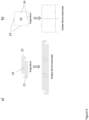
- An example of such assembly to make an EMAS is shown schematically in figure 4a ).
- the figure is a drawing schematically illustrating an arrestor-bed 1 made up of a plurality of rows 2, each made up of several prefabricated blocks 10 of a compactible energy absorbing material placed side by side.
- each prefabricated block 10 in the bulk part of the arrestor-bed is made up of a plurality, here four, layers 9 of smaller blocks 7 stacked and adhered together on top of each other.
- the tapering-off at the front end and/or at the sides of the arrestor-bed may be obtained by simply applying a smaller number of smaller blocks in the stack for the first rows of the arrestor-bed and/or at the ends of each row.
- the blocks may have a stratified layered structure where each layer is made of smaller blocks 8 and where the small blocks each layer is offset relative to the layer beneath it such that the smaller blocks 8 form a brick pattern, such as shown in figure 4b ).
- the prefabricated blocks comprises a vertical stack of a plurality of stratified layers 9 adhered to each other and where each stratified layer 9 consists of a second plurality of smaller blocks 8 arranged in a single horizontal plane and where the smaller blocks 8 of a stratified layer 9 are offset relative to plurality of smaller blocks 8 of the stratified layer 9 beneath and/or above it from a bottom layer to a top layer such that the smaller blocks 8 of the prefabricated block form a brick pattern.
- Such a construction will obtain an arrestor-bed with more monolithic mechanical properties.
- the arrestor-bed may comprise a covering layer on top of the compactible energy absorbing material to protect it from the environment, jet blast, and so on.
- the invention may apply any known and conceivable covering layer known to the skilled person as suited for arrestor-beds made of a foamed/- compactible energy adsorbing material.
- suitable covering layers include thin plastic tops, cement board tops, polymer coatings or sealants, paint, or a combination thereof.
- the example embodiments shown in figures 4a) and 4b ) comprise a covering layer 5.
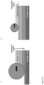
- the arrestor-bed may in some embodiments have a depth-variation in the compressive strength with increasing compressive strength with increased depth of the bed. This provides the arrestor-bed with improved performance with mixed vehicle/aircraft since the wheels of the lighter vehicles will only engage the upper softer layer(s) while the wheels of a heavier vehicle/aircraft will engage deeper into to the arrestor-bed as illustrated schematically in figures 3a) and 3b ).
- the depth-variation in the compressive strength may be obtained by simply gluing together smaller blocks 7, 8 with gradually stronger compressive strength at lower depths such that the bottom layer has the highest compressive strength and the top the weakest each successive layer has a weaker compressive strength than the small block below it. An example of such embodiment is shown in figures 3a) and 3b ).
- the upper layer will produce a softer material response under a vehicle/aircraft tire loading than solid compactible energy absorbing material, thereby acting similar to a lower density compactible energy absorbing material with a lower compaction strength.
- the lower strata will produce a firmer material response under aircraft tire loading; in the limit, this strength will approach that of the solid compactible energy absorbing material.
- the lowest layer may be a continuous compactible energy absorbing material with no voids at all.
- the one or the second plurality of smaller blocks 7, 8 of the top layer 9 of the stratified prefabricated block 10 has/have a first compressive strength
- the one or the second plurality of smaller blocks 7, 8 of the first stratified layer 9 below the top layer has/have a second compressive strength
- the one or the second plurality of smaller blocks 7, 8 of the second stratified layer 9 below the top layer has/have a third compressive strength, and so until the bottom stratified layer 9, and where the first compressive strength ⁇ the second compressive strength ⁇ the third compressive strength and so on until the bottom stratified layer 9.
- angle a towards the longitudinal centre axis of the arrestor-bed is an angle formed in a horizontal plane such that the inclination of the linear lanes causes a lateral force on a vertically oriented wheel travelling in a longitudinal direction through the arrestor-bed.
- angle a relates to the angle at which the linear lanes of prefabricated blocks are angled in the horizontal plane towards the longitudinal centre axis of the arrestor-bed in the direction of travel as illustrated schematically in figure 5 .
- the figure is a drawing showing an example embodiment of an arrestor-bed 1 assembled by prefabricated blocks 10 arranged in a set of linear lanes or columns indicated in the drawing by their longitudinal sides 21.
- the figure also indicates one linear lane 11 of prefabricated blocks 10 by the stapled square marked with reference number 11, and the direction of one row 2 by the stapled square marked with reference number 2.
- the arrestor-bed has a front end which a vehicle/aircraft to be stopped will arrive and enter the arrestor-bed in the travel direction indicated by the two stapled arrows.
- the tilting of the linear lanes is such that they lean towards the longitudinal centre axis, indicated by the stapled line marked with A-A', from both sides of the axis.
- the set of linear lanes of prefabricated blocks may be angled with an angle a, where 0° ⁇ ⁇ ⁇ 28°, preferably 1 ⁇ ⁇ ⁇ 25°, more preferably 2° ⁇ ⁇ ⁇ 23°, more preferably 3° ⁇ ⁇ ⁇ 20°, more preferably 4° ⁇ a ⁇ 15°, more preferably 5° ⁇ ⁇ ⁇ 15°, and most preferably 5° ⁇ ⁇ ⁇ 10° towards the longitudinal centre axis of the bed forming an inverted V-pattern relative to a direction from the front end to the back end of the arrestor-bed.
- the prefabricated blocks may be shaped such they interlock with each other when assembled to facilitate assembly at the runway construction site.
- the prefabricated blocks may feature interlocking geometric features at their edges.
- the connecting features may be designed to interlock either in the elevation orientation by e.g. a tongue and groove type interlocking mechanism such as illustrated in figure 6a ) of be designed to interlock in a plan orientation, by e.g. complementary male and female jigsaw puzzle resembling geometric structures such as shown in figure 6b).
- Figure 6a illustrates schematically a single prefabricated block and an assembly of three blocks.
- the blocks are seen from a lateral side and have a groove type geometric structure 21 and a tongue type geometric structure 22 at the opposite side such that when they are assembled in lanes, the groove of a block interlocks with the tongue of the next block in the lane.
- figure 6b which illustrates a single prefabricated block 10 and an assembly of four blocks as seen from above, where the prefabricated block 10 has two male geometric structures 23 and two female geometric structures 24 which interlocks with each other when assembled.
- the interlocks may be designed with a range of interlock tolerances from one millimeter up to several centimeters, to accommodate the thermal expansion of a large bed comprised of many interlocking blocks.
- the interlocking features may also provide a smoother arresting force on the aircraft by eliminating gaps between blocks, as such gaps may produce an oscillating speed-bump effect on aircraft tires during arrestment.
- the blocks with depth-variation may have inclined stratified layers oriented towards the centreline of the arrestor-bed. That is, the stratified layers are inclined such that they slope down towards the centreline by having the stratified layers 9 of the prefabricated blocks 10 inclined such that the stratified layers 9 are substantially parallel (i.e. horizontal) with the longitudinal centre axis in the longitudinal direction of the arrestor-bed and slope downwards in lateral direction towards the longitudinal centre axis of the arrestor-bed.
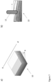
- Figure 7a is a perspective drawing seen from the side and from the above of a single block 10 having six layers 9 of compactible energy absorbing material with gradually weaker compressive strength toward the top.
- each stratified layer is somewhat tilted towards the centreline shown as a stapled line marked with A and A'.
- Figure 7b illustrates the same block as in figure 7a ), but now seen from the side of a front side surface.
- a wheel 12 entering the block 10 and running in longitudinal direction will be in contact with relatively more of the weak compactible energy absorbing material on its right side (relative to the direction of travel) and thus be subject to a lateral force towards the centreline, as indicated by the black arrow on the figure.
- FIG 8 An example embodiment of an arrestor-bed assembled by blocks with depth-variation and inclined stratified layers is shown in figure 8 .
- the arrestor-bed 1 comprises eight blocks with depth-variation and inclined stratified layers in each row (lateral direction), four blocks 10 on the left side and four blocks 13 on the right side of the centreline A-A'.
- the inclination of the layers of the blocks 10 on the left side of the centreline makes the stratified layers tilt downwards to their right side, while the inclination of the layers of the blocks 13 on the right side of the centreline makes the stratified layers tilt downwards to their left side.
- An aircraft entering the arrestor-bed out of line e.g.
- the prefabricated blocks may comprise one or more linear throughgoing voids, channels or holes arranged normal to the lateral side of the blocks such that the throughgoing voids, channels or holes of successive blocks in each linear lane aligns and forms throughgoing voids, channels or holes extending through the entire linear lane of blocks.
- the invention is described in further detail by way of an example embodiment of an arrestor-bed intended to arrest aircrafts entering the bed.
- the example embodiment of the arrestor-bed is assembled by prefabricated blocks of foamed glass having a compression strength of 344.7 kPa (50 psi) assembled to form linear lanes of prefabricated blocks angled at 15 ° towards the longitudinal centre axis of the arrestor-bed.
- the linear lanes form a pattern similar to the example embodiment illustrated in figure 5 .
- the longitudinal side surfaces between adjacent linear lanes of blocks in the arrestor-bed form a set of angled zones of relative weak compression strength as compared to compression strength of the blocks. This creates a directional centering force. In automobiles this type of force can be observed by rutting in the road surface, in which contexts it is referred to as tramlining.
- the effective lateral loading of crushable foam on an aircraft tire will be dependent upon the angle of obliquity of the tire to the channels or lanes of material.
- the total lateral and longitudinal forces (Fx and Fy, respectively) can be calculated by integrating the force components around the perimeter of the tire that is in contact with the crushable foam. As the path of the tire travel becomes more perpendicular to the boundary surface of the foam layer, the average lateral force will decline toward zero. Similarly, once the tire fully crosses the boundary of the crushable foam layer, the lateral force equilibrates, and the net force will decline toward zero.
- the lateral force on the main gear tire of a B737 entering into a linear lane of blocks at different angles are calculated for multiple inclination angles of 15, 30, 45, 60, and 75 ° and presented in figure 9 .
- the main gear of the B737 which has a rated load of 199 kN (44 700 lbf) has a diameter of 113 cm (44.5 inches) and a width of 42 cm (16.5 inches).
- the layup scenario was simplified to include a single exposed face of crushable foam adjacent to a void space.
- the directional loads were calculated by integration along the arclength of tire in contact with the crushable foam. This calculation was performed at a series of positions as the tire progressively entered the crushable foam by movement in the direction of travel.
- the lateral force in this example reaches the highest magnitude and is sustained for the longest length of travel at a shallow 15-degree angle of obliquity.
- the lateral loads become weaker and briefer when the material is more perpendicular to the direction of travel at obliquity angles greater than 45 degrees.
Landscapes
- Engineering & Computer Science (AREA)
- Mechanical Engineering (AREA)
- Architecture (AREA)
- Civil Engineering (AREA)
- Structural Engineering (AREA)
- Aviation & Aerospace Engineering (AREA)
- Laminated Bodies (AREA)
- Road Paving Structures (AREA)
- Crystals, And After-Treatments Of Crystals (AREA)
Claims (11)
- Système d'arrêt de véhicule comprenant un lit d'arrêt (1) posé sur une base/un sol et ayant un axe central longitudinal s'étendant depuis une extrémité avant, l'extrémité avant étant un côté du lit d'arrêt (1) par lequel un véhicule est censé pénétrer dans le lit d'arrêt (1), jusqu'à une extrémité arrière à l'opposé de l'extrémité avant, dans lequel le lit d'arrêt comprend :une pluralité de blocs préfabriqués (10) d'un matériau alvéolaire compactable que l'on a assemblés côte à côte et fait adhérer les uns aux autres, dans lequel l'ensemble de blocs préfabriqués comprend un ensemble de nombre pair de bandes linéaires (11) de blocs préfabriqués (10), la moitié de l'ensemble est située sur un côté gauche et une moitié de l'ensemble est située sur un côté droit de l'axe central longitudinal du lit d'arrêt,caractérisé en ce que chaque bande linéaire (11) de blocs préfabriqués (10) est inclinée d'un angle α, où 0° < α ≤ 30°, vers l'axe central longitudinal du lit d'arrêt (1) de telle sorte que l'ensemble de bandes linéaires (11), vu de dessus, forme une série de motifs en V inversé successifs le long de l'axe central longitudinal du lit d'arrêt, etles blocs préfabriqués (10) sont façonnés et dimensionnés de telle sorte qu'ils couvrent/pavent entièrement une aire de surface de la base/du sol sur lequel est posé le lit d'arrêt.
- Système d'arrêt de véhicule selon la revendication 1, dans lequel l'ensemble de bandes linéaires de résistance à la compression relativement faible est incliné d'un angle α, où 0° < α ≤ 28°, de préférence 1° ≤ α ≤ 25°, mieux 2° ≤ α ≤ 23°, mieux encore 3° ≤ α ≤ 20°, mieux 4° ≤ α ≤ 15°, mieux encore 5° ≤ α ≤ 15°, et idéalement 5° ≤ α ≤ 10°.
- Système d'arrêt de véhicule selon la revendication 1 ou 2, dans lequel le matériau alvéolaire compactable est un matériau choisi parmi le ciment cellulaire, les matériaux cimentaires cellulaires, le ciment mousse, la mousse polymère, les structures en nid d'abeilles, les structures en nid d'abeilles métalliques, la vermiculite, la perlite, les céramiques, le verre mousse et les autres matériaux compactables/déformables isotropes ou anisotropes, et les combinaisons de ceux-ci.
- Système d'arrêt de véhicule selon une quelconque revendication précédente, dans lequel la résistance à la compression du matériau alvéolaire compactable peut avantageusement se situer dans la plage de 6,9 à 689,8 kPa (1 à 100 psi), de préférence de 68,9 à 620,5 kPa (10 à 90 psi), mieux de 137,9 à 551,8 kPa (20 à 80 psi), mieux encore de 206,8 à 482,6 kPa (30 à 70 psi), et idéalement de 275,8 à 413,7 kPa (40 à 60 psi).
- Système d'arrêt de véhicule selon une quelconque revendication précédente, dans lequel le lit d'arrêt présente une variation sur la profondeur de la résistance à la compression avec une résistance à la compression croissante avec une plus grande profondeur du lit obtenue en dotant le lit d'arrêt d'une structure stratifiée de multiples couches de matériau alvéolaire compactable ayant une plus forte résistance à la compression pour chaque couche successive de matériau alvéolaire compactable en descendant jusqu'à la couche inférieure du lit d'arrêt.
- Système d'arrêt de véhicule selon une quelconque revendication précédente, dans lequel on a fait adhérer les blocs préfabriqués les uns aux autres par collage, masticage, ou avec du ruban adhésif.
- Système d'arrêt de véhicule selon une quelconque revendication précédente, dans lequel le bloc préfabriqué (10) :comprend un empilement vertical d'une pluralité de couches stratifiées (9) adhérant les unes aux autres et où chaque couche stratifiée (9) consiste en un bloc plus petit (7), oucomprend un empilement vertical d'une pluralité de couches stratifiées (9) adhérant les unes aux autres et où chaque couche stratifiée (9) consiste en une deuxième pluralité de blocs plus petits (8) disposés dans un seul plan horizontal et où les blocs plus petits (8) d'une couche stratifiée (9) sont décalés par rapport à la pluralité de blocs plus petits (8) de la couche stratifiée (9) en dessous et/ou au-dessus de celle-ci depuis une couche inférieure jusqu'à une couche supérieure de telle sorte que les blocs plus petits (8) du bloc préfabriqué (10) forment un motif de briques.
- Système d'arrêt de véhicule selon la revendication 7, dans lequel le bloc plus petit ou la deuxième pluralité de blocs plus petits (7, 8) de la couche supérieure (9) du bloc préfabriqué stratifié (10) a/ont une première résistance à la compression, le bloc plus petit ou la deuxième pluralité de blocs plus petits (7, 8) de la première couche stratifiée (9) en dessous de la couche supérieure a/ont une deuxième résistance à la compression, le bloc plus petit ou la deuxième pluralité de blocs plus petits (7, 8) de la deuxième couche stratifiée (9) en dessous de la couche supérieure a/ont une troisième résistance à la compression, et ainsi de suite jusqu'à la couche stratifiée inférieure (9), et dans lequel la première résistance à la compression < la deuxième résistance à la compression < la troisième résistance à la compression, et ainsi de suite jusqu'à la couche stratifiée inférieure (9).
- Système d'arrêt de véhicule selon la revendication 8, dans lequel les couches stratifiées (9) des blocs préfabriqués (10) sont inclinées de telle sorte que les couches stratifiées (9) sont sensiblement parallèles à un axe central longitudinal dans la direction longitudinale et suivent une pente descendante dans une direction latérale vers l'axe central longitudinal du lit d'arrêt.
- Système d'arrêt de véhicule selon une quelconque revendication précédente, dans lequel le bloc préfabriqué (10) comprend en outre des éléments géométriques d'emboîtement sur ses bords.
- Système d'arrêt de véhicule selon une quelconque revendication précédente, dans lequel le bloc préfabriqué (10) comprend en outre un ou plusieurs vides, canaux ou trous traversants linéaires orientés perpendiculairement à un côté latéral du bloc.
Applications Claiming Priority (2)
| Application Number | Priority Date | Filing Date | Title |
|---|---|---|---|
| NO20210933A NO346863B1 (en) | 2021-07-21 | 2021-07-21 | Engineered Material Arresting System |
| PCT/EP2022/064042 WO2023001432A1 (fr) | 2021-07-21 | 2022-05-24 | Système d'arrêt à matériau d'ingénierie |
Publications (3)
| Publication Number | Publication Date |
|---|---|
| EP4373748A1 EP4373748A1 (fr) | 2024-05-29 |
| EP4373748B1 true EP4373748B1 (fr) | 2025-06-18 |
| EP4373748C0 EP4373748C0 (fr) | 2025-06-18 |
Family
ID=82058424
Family Applications (1)
| Application Number | Title | Priority Date | Filing Date |
|---|---|---|---|
| EP22730447.4A Active EP4373748B1 (fr) | 2021-07-21 | 2022-05-24 | Système d'arrêt en matériau d'ingénierie |
Country Status (5)
| Country | Link |
|---|---|
| US (1) | US20250091726A1 (fr) |
| EP (1) | EP4373748B1 (fr) |
| JP (1) | JP7797620B2 (fr) |
| NO (1) | NO346863B1 (fr) |
| WO (1) | WO2023001432A1 (fr) |
Family Cites Families (14)
| Publication number | Priority date | Publication date | Assignee | Title |
|---|---|---|---|---|
| SE315507B (fr) * | 1964-08-28 | 1969-09-29 | Harvey Aluminum Inc | |
| US3967704A (en) | 1968-10-07 | 1976-07-06 | British Industrial Plastics Limited | Vehicle decelerating means |
| GB1282103A (en) * | 1968-10-07 | 1972-07-19 | British Industrial Plastics | Vehicle decelerating means |
| US5193764A (en) * | 1991-10-01 | 1993-03-16 | Manville Corporation | Aircraft arresting system |
| US5885025A (en) | 1997-02-07 | 1999-03-23 | Datron Inc. | Vehicle arresting bed systems |
| JP2001140204A (ja) * | 1999-11-17 | 2001-05-22 | Yours Country:Kk | 舗装用ブロック |
| DE10041492B4 (de) * | 2000-08-24 | 2007-06-21 | Arnold Vogts | Matte als Notlandehilfe für Flugzeuge |
| US6685387B2 (en) * | 2001-09-13 | 2004-02-03 | Engineered Arresting Systems Corporation | Jet blast resistant vehicle arresting blocks, beds and methods |
| JP2012206236A (ja) | 2011-03-30 | 2012-10-25 | Brother Industries Ltd | 切断装置、及び保持部材 |
| CN102936880B (zh) * | 2012-11-23 | 2015-10-14 | 中国民航科学技术研究院 | 复合式拦阻单元体及其生产方法 |
| MX2016011389A (es) * | 2014-03-03 | 2016-12-07 | Eng Arresting Systems Corp | Materiales y estructuras de macro-patron para sistemas de detencion de vehiculos. |
| CA2985374C (fr) * | 2015-05-18 | 2020-07-28 | Engineered Arresting Systems Corporation | Materiau d'absorption d'energie en couches suspendues pour systemes d'arret de vehicule |
| WO2018158756A1 (fr) * | 2017-03-03 | 2018-09-07 | Run Way Safe Ipr Ab | Système d'arrêt à matériau modifié et ses procédés de formation |
| CN110344298B (zh) * | 2018-04-02 | 2022-03-08 | 航科院(北京)科技发展有限公司 | 一种用于emas的分层式缓冲吸能结构体及制备方法 |
-
2021
- 2021-07-21 NO NO20210933A patent/NO346863B1/en unknown
-
2022
- 2022-05-24 US US18/580,882 patent/US20250091726A1/en active Pending
- 2022-05-24 JP JP2024503844A patent/JP7797620B2/ja active Active
- 2022-05-24 EP EP22730447.4A patent/EP4373748B1/fr active Active
- 2022-05-24 WO PCT/EP2022/064042 patent/WO2023001432A1/fr not_active Ceased
Also Published As
| Publication number | Publication date |
|---|---|
| EP4373748A1 (fr) | 2024-05-29 |
| JP7797620B2 (ja) | 2026-01-13 |
| EP4373748C0 (fr) | 2025-06-18 |
| JP2024527864A (ja) | 2024-07-26 |
| NO20210933A1 (en) | 2023-01-23 |
| WO2023001432A1 (fr) | 2023-01-26 |
| US20250091726A1 (en) | 2025-03-20 |
| NO346863B1 (en) | 2023-02-06 |
Similar Documents
| Publication | Publication Date | Title |
|---|---|---|
| EP2523857B1 (fr) | Lit d'arrêt pour véhicules | |
| JP3868504B2 (ja) | 乗物拘束路盤システム | |
| EP3297920B1 (fr) | Matériau d'absorption d'énergie en couches suspendues pour systèmes d'arrêt de véhicule | |
| JP3929077B2 (ja) | 機体拘束ユニットおよびその製造方法 | |
| US20150247298A1 (en) | Macro-patterned materials and structures for vehicle arresting systems | |
| EP3589546B1 (fr) | Système d'immobilisation en matériau transformé et procédés pour le former | |
| EP4373747B1 (fr) | Système d'arrêt en matériau d'ingénierie | |
| EP4373748B1 (fr) | Système d'arrêt en matériau d'ingénierie | |
| CN110344298B (zh) | 一种用于emas的分层式缓冲吸能结构体及制备方法 |
Legal Events
| Date | Code | Title | Description |
|---|---|---|---|
| STAA | Information on the status of an ep patent application or granted ep patent |
Free format text: STATUS: UNKNOWN |
|
| STAA | Information on the status of an ep patent application or granted ep patent |
Free format text: STATUS: THE INTERNATIONAL PUBLICATION HAS BEEN MADE |
|
| PUAI | Public reference made under article 153(3) epc to a published international application that has entered the european phase |
Free format text: ORIGINAL CODE: 0009012 |
|
| STAA | Information on the status of an ep patent application or granted ep patent |
Free format text: STATUS: REQUEST FOR EXAMINATION WAS MADE |
|
| 17P | Request for examination filed |
Effective date: 20240220 |
|
| AK | Designated contracting states |
Kind code of ref document: A1 Designated state(s): AL AT BE BG CH CY CZ DE DK EE ES FI FR GB GR HR HU IE IS IT LI LT LU LV MC MK MT NL NO PL PT RO RS SE SI SK SM TR |
|
| DAV | Request for validation of the european patent (deleted) | ||
| DAX | Request for extension of the european patent (deleted) | ||
| GRAP | Despatch of communication of intention to grant a patent |
Free format text: ORIGINAL CODE: EPIDOSNIGR1 |
|
| STAA | Information on the status of an ep patent application or granted ep patent |
Free format text: STATUS: GRANT OF PATENT IS INTENDED |
|
| INTG | Intention to grant announced |
Effective date: 20241121 |
|
| GRAJ | Information related to disapproval of communication of intention to grant by the applicant or resumption of examination proceedings by the epo deleted |
Free format text: ORIGINAL CODE: EPIDOSDIGR1 |
|
| STAA | Information on the status of an ep patent application or granted ep patent |
Free format text: STATUS: REQUEST FOR EXAMINATION WAS MADE |
|
| GRAP | Despatch of communication of intention to grant a patent |
Free format text: ORIGINAL CODE: EPIDOSNIGR1 |
|
| STAA | Information on the status of an ep patent application or granted ep patent |
Free format text: STATUS: GRANT OF PATENT IS INTENDED |
|
| INTC | Intention to grant announced (deleted) | ||
| RAP3 | Party data changed (applicant data changed or rights of an application transferred) |
Owner name: RUNWAY SAFE IPR AB |
|
| GRAS | Grant fee paid |
Free format text: ORIGINAL CODE: EPIDOSNIGR3 |
|
| GRAA | (expected) grant |
Free format text: ORIGINAL CODE: 0009210 |
|
| STAA | Information on the status of an ep patent application or granted ep patent |
Free format text: STATUS: THE PATENT HAS BEEN GRANTED |
|
| INTG | Intention to grant announced |
Effective date: 20250417 |
|
| AK | Designated contracting states |
Kind code of ref document: B1 Designated state(s): AL AT BE BG CH CY CZ DE DK EE ES FI FR GB GR HR HU IE IS IT LI LT LU LV MC MK MT NL NO PL PT RO RS SE SI SK SM TR |
|
| REG | Reference to a national code |
Ref country code: GB Ref legal event code: FG4D |
|
| REG | Reference to a national code |
Ref country code: CH Ref legal event code: EP |
|
| REG | Reference to a national code |
Ref country code: DE Ref legal event code: R096 Ref document number: 602022016123 Country of ref document: DE |
|
| REG | Reference to a national code |
Ref country code: CH Ref legal event code: EP |
|
| REG | Reference to a national code |
Ref country code: IE Ref legal event code: FG4D |
|
| U01 | Request for unitary effect filed |
Effective date: 20250618 |
|
| U07 | Unitary effect registered |
Designated state(s): AT BE BG DE DK EE FI FR IT LT LU LV MT NL PT RO SE SI Effective date: 20250626 |
|
| PG25 | Lapsed in a contracting state [announced via postgrant information from national office to epo] |
Ref country code: GR Free format text: LAPSE BECAUSE OF FAILURE TO SUBMIT A TRANSLATION OF THE DESCRIPTION OR TO PAY THE FEE WITHIN THE PRESCRIBED TIME-LIMIT Effective date: 20250919 |
|
| PG25 | Lapsed in a contracting state [announced via postgrant information from national office to epo] |
Ref country code: HR Free format text: LAPSE BECAUSE OF FAILURE TO SUBMIT A TRANSLATION OF THE DESCRIPTION OR TO PAY THE FEE WITHIN THE PRESCRIBED TIME-LIMIT Effective date: 20250618 |
|
| PG25 | Lapsed in a contracting state [announced via postgrant information from national office to epo] |
Ref country code: RS Free format text: LAPSE BECAUSE OF FAILURE TO SUBMIT A TRANSLATION OF THE DESCRIPTION OR TO PAY THE FEE WITHIN THE PRESCRIBED TIME-LIMIT Effective date: 20250918 |
|
| PG25 | Lapsed in a contracting state [announced via postgrant information from national office to epo] |
Ref country code: IS Free format text: LAPSE BECAUSE OF FAILURE TO SUBMIT A TRANSLATION OF THE DESCRIPTION OR TO PAY THE FEE WITHIN THE PRESCRIBED TIME-LIMIT Effective date: 20251018 |
|
| PG25 | Lapsed in a contracting state [announced via postgrant information from national office to epo] |
Ref country code: SM Free format text: LAPSE BECAUSE OF FAILURE TO SUBMIT A TRANSLATION OF THE DESCRIPTION OR TO PAY THE FEE WITHIN THE PRESCRIBED TIME-LIMIT Effective date: 20250618 |
|
| PG25 | Lapsed in a contracting state [announced via postgrant information from national office to epo] |
Ref country code: CZ Free format text: LAPSE BECAUSE OF FAILURE TO SUBMIT A TRANSLATION OF THE DESCRIPTION OR TO PAY THE FEE WITHIN THE PRESCRIBED TIME-LIMIT Effective date: 20250618 |
|
| PG25 | Lapsed in a contracting state [announced via postgrant information from national office to epo] |
Ref country code: PL Free format text: LAPSE BECAUSE OF FAILURE TO SUBMIT A TRANSLATION OF THE DESCRIPTION OR TO PAY THE FEE WITHIN THE PRESCRIBED TIME-LIMIT Effective date: 20250618 |
|
| PG25 | Lapsed in a contracting state [announced via postgrant information from national office to epo] |
Ref country code: SK Free format text: LAPSE BECAUSE OF FAILURE TO SUBMIT A TRANSLATION OF THE DESCRIPTION OR TO PAY THE FEE WITHIN THE PRESCRIBED TIME-LIMIT Effective date: 20250618 |
|
| PG25 | Lapsed in a contracting state [announced via postgrant information from national office to epo] |
Ref country code: ES Free format text: LAPSE BECAUSE OF FAILURE TO SUBMIT A TRANSLATION OF THE DESCRIPTION OR TO PAY THE FEE WITHIN THE PRESCRIBED TIME-LIMIT Effective date: 20250618 |
|
| PLBE | No opposition filed within time limit |
Free format text: ORIGINAL CODE: 0009261 |
|
| STAA | Information on the status of an ep patent application or granted ep patent |
Free format text: STATUS: NO OPPOSITION FILED WITHIN TIME LIMIT |