EP4375004A1 - Batterie secondaire et procédé de fabrication de cette batterie secondaire - Google Patents
Batterie secondaire et procédé de fabrication de cette batterie secondaire Download PDFInfo
- Publication number
- EP4375004A1 EP4375004A1 EP23207468.2A EP23207468A EP4375004A1 EP 4375004 A1 EP4375004 A1 EP 4375004A1 EP 23207468 A EP23207468 A EP 23207468A EP 4375004 A1 EP4375004 A1 EP 4375004A1
- Authority
- EP
- European Patent Office
- Prior art keywords
- current collector
- plate
- substrate tab
- electrode
- secondary battery
- Prior art date
- Legal status (The legal status is an assumption and is not a legal conclusion. Google has not performed a legal analysis and makes no representation as to the accuracy of the status listed.)
- Granted
Links
Images


Classifications
-
- B—PERFORMING OPERATIONS; TRANSPORTING
- B23—MACHINE TOOLS; METAL-WORKING NOT OTHERWISE PROVIDED FOR
- B23K—SOLDERING OR UNSOLDERING; WELDING; CLADDING OR PLATING BY SOLDERING OR WELDING; CUTTING BY APPLYING HEAT LOCALLY, e.g. FLAME CUTTING; WORKING BY LASER BEAM
- B23K26/00—Working by laser beam, e.g. welding, cutting or boring
- B23K26/20—Bonding
- B23K26/21—Bonding by welding
- B23K26/24—Seam welding
- B23K26/244—Overlap seam welding
-
- H—ELECTRICITY
- H01—ELECTRIC ELEMENTS
- H01M—PROCESSES OR MEANS, e.g. BATTERIES, FOR THE DIRECT CONVERSION OF CHEMICAL ENERGY INTO ELECTRICAL ENERGY
- H01M10/00—Secondary cells; Manufacture thereof
- H01M10/04—Construction or manufacture in general
-
- H—ELECTRICITY
- H01—ELECTRIC ELEMENTS
- H01M—PROCESSES OR MEANS, e.g. BATTERIES, FOR THE DIRECT CONVERSION OF CHEMICAL ENERGY INTO ELECTRICAL ENERGY
- H01M50/00—Constructional details or processes of manufacture of the non-active parts of electrochemical cells other than fuel cells, e.g. hybrid cells
- H01M50/50—Current conducting connections for cells or batteries
- H01M50/528—Fixed electrical connections, i.e. not intended for disconnection
-
- H—ELECTRICITY
- H01—ELECTRIC ELEMENTS
- H01M—PROCESSES OR MEANS, e.g. BATTERIES, FOR THE DIRECT CONVERSION OF CHEMICAL ENERGY INTO ELECTRICAL ENERGY
- H01M50/00—Constructional details or processes of manufacture of the non-active parts of electrochemical cells other than fuel cells, e.g. hybrid cells
- H01M50/50—Current conducting connections for cells or batteries
- H01M50/531—Electrode connections inside a battery casing
- H01M50/536—Electrode connections inside a battery casing characterised by the method of fixing the leads to the electrodes, e.g. by welding
-
- B—PERFORMING OPERATIONS; TRANSPORTING
- B23—MACHINE TOOLS; METAL-WORKING NOT OTHERWISE PROVIDED FOR
- B23K—SOLDERING OR UNSOLDERING; WELDING; CLADDING OR PLATING BY SOLDERING OR WELDING; CUTTING BY APPLYING HEAT LOCALLY, e.g. FLAME CUTTING; WORKING BY LASER BEAM
- B23K26/00—Working by laser beam, e.g. welding, cutting or boring
- B23K26/0093—Working by laser beam, e.g. welding, cutting or boring combined with mechanical machining or metal-working covered by other subclasses than B23K
-
- H—ELECTRICITY
- H01—ELECTRIC ELEMENTS
- H01M—PROCESSES OR MEANS, e.g. BATTERIES, FOR THE DIRECT CONVERSION OF CHEMICAL ENERGY INTO ELECTRICAL ENERGY
- H01M10/00—Secondary cells; Manufacture thereof
- H01M10/05—Accumulators with non-aqueous electrolyte
- H01M10/058—Construction or manufacture
- H01M10/0587—Construction or manufacture of accumulators having only wound construction elements, i.e. wound positive electrodes, wound negative electrodes and wound separators
-
- H—ELECTRICITY
- H01—ELECTRIC ELEMENTS
- H01M—PROCESSES OR MEANS, e.g. BATTERIES, FOR THE DIRECT CONVERSION OF CHEMICAL ENERGY INTO ELECTRICAL ENERGY
- H01M4/00—Electrodes
- H01M4/02—Electrodes composed of, or comprising, active material
-
- H—ELECTRICITY
- H01—ELECTRIC ELEMENTS
- H01M—PROCESSES OR MEANS, e.g. BATTERIES, FOR THE DIRECT CONVERSION OF CHEMICAL ENERGY INTO ELECTRICAL ENERGY
- H01M50/00—Constructional details or processes of manufacture of the non-active parts of electrochemical cells other than fuel cells, e.g. hybrid cells
- H01M50/10—Primary casings; Jackets or wrappings
- H01M50/147—Lids or covers
- H01M50/148—Lids or covers characterised by their shape
- H01M50/15—Lids or covers characterised by their shape for prismatic or rectangular cells
-
- H—ELECTRICITY
- H01—ELECTRIC ELEMENTS
- H01M—PROCESSES OR MEANS, e.g. BATTERIES, FOR THE DIRECT CONVERSION OF CHEMICAL ENERGY INTO ELECTRICAL ENERGY
- H01M50/00—Constructional details or processes of manufacture of the non-active parts of electrochemical cells other than fuel cells, e.g. hybrid cells
- H01M50/10—Primary casings; Jackets or wrappings
- H01M50/172—Arrangements of electric connectors penetrating the casing
- H01M50/174—Arrangements of electric connectors penetrating the casing adapted for the shape of the cells
- H01M50/176—Arrangements of electric connectors penetrating the casing adapted for the shape of the cells for prismatic or rectangular cells
-
- H—ELECTRICITY
- H01—ELECTRIC ELEMENTS
- H01M—PROCESSES OR MEANS, e.g. BATTERIES, FOR THE DIRECT CONVERSION OF CHEMICAL ENERGY INTO ELECTRICAL ENERGY
- H01M50/00—Constructional details or processes of manufacture of the non-active parts of electrochemical cells other than fuel cells, e.g. hybrid cells
- H01M50/40—Separators; Membranes; Diaphragms; Spacing elements inside cells
- H01M50/46—Separators, membranes or diaphragms characterised by their combination with electrodes
-
- H—ELECTRICITY
- H01—ELECTRIC ELEMENTS
- H01M—PROCESSES OR MEANS, e.g. BATTERIES, FOR THE DIRECT CONVERSION OF CHEMICAL ENERGY INTO ELECTRICAL ENERGY
- H01M50/00—Constructional details or processes of manufacture of the non-active parts of electrochemical cells other than fuel cells, e.g. hybrid cells
- H01M50/50—Current conducting connections for cells or batteries
- H01M50/531—Electrode connections inside a battery casing
- H01M50/533—Electrode connections inside a battery casing characterised by the shape of the leads or tabs
-
- H—ELECTRICITY
- H01—ELECTRIC ELEMENTS
- H01M—PROCESSES OR MEANS, e.g. BATTERIES, FOR THE DIRECT CONVERSION OF CHEMICAL ENERGY INTO ELECTRICAL ENERGY
- H01M50/00—Constructional details or processes of manufacture of the non-active parts of electrochemical cells other than fuel cells, e.g. hybrid cells
- H01M50/50—Current conducting connections for cells or batteries
- H01M50/531—Electrode connections inside a battery casing
- H01M50/534—Electrode connections inside a battery casing characterised by the material of the leads or tabs
-
- H—ELECTRICITY
- H01—ELECTRIC ELEMENTS
- H01M—PROCESSES OR MEANS, e.g. BATTERIES, FOR THE DIRECT CONVERSION OF CHEMICAL ENERGY INTO ELECTRICAL ENERGY
- H01M50/00—Constructional details or processes of manufacture of the non-active parts of electrochemical cells other than fuel cells, e.g. hybrid cells
- H01M50/50—Current conducting connections for cells or batteries
- H01M50/531—Electrode connections inside a battery casing
- H01M50/538—Connection of several leads or tabs of wound or folded electrode stacks
-
- H—ELECTRICITY
- H01—ELECTRIC ELEMENTS
- H01M—PROCESSES OR MEANS, e.g. BATTERIES, FOR THE DIRECT CONVERSION OF CHEMICAL ENERGY INTO ELECTRICAL ENERGY
- H01M50/00—Constructional details or processes of manufacture of the non-active parts of electrochemical cells other than fuel cells, e.g. hybrid cells
- H01M50/50—Current conducting connections for cells or batteries
- H01M50/531—Electrode connections inside a battery casing
- H01M50/54—Connection of several leads or tabs of plate-like electrode stacks, e.g. electrode pole straps or bridges
-
- B—PERFORMING OPERATIONS; TRANSPORTING
- B23—MACHINE TOOLS; METAL-WORKING NOT OTHERWISE PROVIDED FOR
- B23K—SOLDERING OR UNSOLDERING; WELDING; CLADDING OR PLATING BY SOLDERING OR WELDING; CUTTING BY APPLYING HEAT LOCALLY, e.g. FLAME CUTTING; WORKING BY LASER BEAM
- B23K2101/00—Articles made by soldering, welding or cutting
- B23K2101/36—Electric or electronic devices
- B23K2101/38—Conductors
-
- Y—GENERAL TAGGING OF NEW TECHNOLOGICAL DEVELOPMENTS; GENERAL TAGGING OF CROSS-SECTIONAL TECHNOLOGIES SPANNING OVER SEVERAL SECTIONS OF THE IPC; TECHNICAL SUBJECTS COVERED BY FORMER USPC CROSS-REFERENCE ART COLLECTIONS [XRACs] AND DIGESTS
- Y02—TECHNOLOGIES OR APPLICATIONS FOR MITIGATION OR ADAPTATION AGAINST CLIMATE CHANGE
- Y02E—REDUCTION OF GREENHOUSE GAS [GHG] EMISSIONS, RELATED TO ENERGY GENERATION, TRANSMISSION OR DISTRIBUTION
- Y02E60/00—Enabling technologies; Technologies with a potential or indirect contribution to GHG emissions mitigation
- Y02E60/10—Energy storage using batteries
-
- Y—GENERAL TAGGING OF NEW TECHNOLOGICAL DEVELOPMENTS; GENERAL TAGGING OF CROSS-SECTIONAL TECHNOLOGIES SPANNING OVER SEVERAL SECTIONS OF THE IPC; TECHNICAL SUBJECTS COVERED BY FORMER USPC CROSS-REFERENCE ART COLLECTIONS [XRACs] AND DIGESTS
- Y02—TECHNOLOGIES OR APPLICATIONS FOR MITIGATION OR ADAPTATION AGAINST CLIMATE CHANGE
- Y02P—CLIMATE CHANGE MITIGATION TECHNOLOGIES IN THE PRODUCTION OR PROCESSING OF GOODS
- Y02P70/00—Climate change mitigation technologies in the production process for final industrial or consumer products
- Y02P70/50—Manufacturing or production processes characterised by the final manufactured product
Definitions
- aspects of embodiments of the present disclosure relate to a secondary battery.
- a secondary battery may include an electrode assembly, which includes a positive electrode plate and a negative electrode plate that are wound or stacked with a separator interposed therebetween, a case accommodating the electrode assembly and an electrolyte, and a cap assembly sealing the case.
- substrate tabs e.g., uncoated tabs
- the substrate tabs and the current collector may be welded together with a laser.
- the substrate tabs may be gathered to one side, the current collector may be placed thereon and pressed, and then, the substrate tabs and the current collector may be welded together with a laser.
- Embodiments of the present disclosure provide a secondary battery having an improved electrode assembly welding structure.
- a secondary battery includes: an electrode assembly; a case accommodating the electrode assembly; and a cap assembly sealing the case and including a pair of current collector plates.
- the electrode assembly includes a first electrode plate having a first substrate tab extending in one direction, a second electrode plate having a second substrate tab extending in another direction than the first substrate tab, and a separator interposed between the first electrode plate and the second electrode plate.
- Each of the current collector plates is electrically connected to one of the first substrate tab and the second substrate tab.
- the current collector plates are laser-welded to the first substrate tab and the second substrate tab, respectively, and a direction of a laser welding portion is parallel to a metal processing direction of the corresponding current collector plate.
- the pair of current collector plates may be a first current collector plate and a second current collector plate.
- the first substrate tab and the second substrate tab may be bent in one direction to be in surface contact with the respective current collector plates.
- the first substrate tab and the second substrate tab may be welded to back beads (back welding beads) formed on rear surfaces of the respective current collector plates by laser welding.
- back beads back welding beads
- the first substrate tab and the second substrate tab may be welded on a rear surface of the respective current collector plates by laser welding.
- the metal processing direction may be an orientation of surface components (surface material structure) of the current collector plate which is formed through rolling.
- the first electrode plate, the second electrode plate, and the separator may be stacked together, and the laser welding direction in the electrode assembly may be perpendicular to an arrangement direction of the first electrode plate and the second electrode plate.
- the first electrode plate, the second electrode plate, and the separator may be stacked together, and the direction of the laser welding portion may be perpendicular to an arrangement direction of the first electrode plate and the second electrode plate in the electrode assembly.
- the current collector plate may have a plate shape, and (two) welding regions of the current collector plate may be separated and divided in a length direction.
- the first current collector plate and the second current collector plate may have a plate shape, and (two) welding regions of the second current collector plate may be separated and divided in a length direction and the (two) welding regions of the first current collector plate may be separated and divided in a length direction.
- a protruding portion of the current collector plate in the length direction may be bent to protrude outwardly from the electrode assembly, and both welding regions (surfaces) of the current collector plate with respect to the protruding portion may be bent toward the electrode assembly.
- a protruding portion of the second current collector plate in the length direction may be bent to protrude outwardly from the electrode assembly, and both welding regions (surfaces) of the second current collector plate with respect to the protruding portion (of the second current collector plate) may be bent toward the electrode assembly and both welding regions (surfaces) of the first current collector plate with respect to the protruding portion (of the first current collector plate) may be bent toward the electrode assembly.
- the welding regions may be both surfaces with respect to the protruding portion of the current collector plate.
- Both ends of the current collector plate may protrude outwardly further than the welding region.
- both ends of the second current collector plate may protrude outwardly further than the welding region; and both ends of the first current collector plate may protrude outwardly further than the welding region. Ends may refer to the ends lengthwise.
- the current collector plate may be made of the same material as the corresponding electrode plate. That is, the first current collector plate may be made of the same material as the first electrode plate. Further, the second current collector plate may be made of the same material as the second electrode plate. This has the advantageous effect that the quality of the laser welding portion is improved.
- the direction of the metal processing direction may be perpendicular to a longitudinal direction of the (first and second) current collector plates.
- the direction of the metal processing direction may be perpendicular to the longitudinal side of the current collector plate.
- a method of manufacturing a secondary battery comprises the following steps:
- the first substrate tab and the second substrate tab may be bent in one direction to be in surface contact with the respective (first and second) current collector plates.
- the current collector plate may be lifted and may be pressed against the corresponding substrate tabs and fixed, e.g. with a jig.
- the first current collector plate may be lifted and may be pressed against the first substrate tabs and fixed, e.g. with a jig.
- the electrically connecting of the first substrate tab and the second substrate tab may comprise forming back beads on a rear surface of the respective (first and second) current collector plates by the laser-welding.
- each of the pair of current collector plates may be processed by a rolling process in order to provide the metal processing direction of the corresponding current collector plate.
- the direction of the metal processing direction may be perpendicular to a longitudinal direction of the current collector plate.
- the direction of the metal processing direction may be perpendicular to the longitudinal side of the current collector plate.
- Embodiments of the present disclosure are provided herein to more completely describe aspects and features of the present disclosure to those of ordinary skill in the art.
- the following embodiments may be modified in various different forms, and the scope of the present disclosure is not limited to the following embodiments. Rather, these embodiments are provided so that the present disclosure will be thorough and complete and will convey the present disclosure to those skilled in the art.
- the expression "at least one of a, b, or c" indicates only a, only b, only c, both a and b, both a and c, both b and c, all of a, b, and c, or variations thereof.
- the terms “use,” “using,” and “used” may be considered synonymous with the terms “utilize,” “utilizing,” and “utilized,” respectively.
- the terms “substantially,” “about,” and similar terms are used as terms of approximation and not as terms of degree, and are intended to account for the inherent variations in measured or calculated values that would be recognized by those of ordinary skill in the art.
- first, second, third, etc. may be used herein to describe various elements, components, regions, layers, and/or sections, these elements, components, regions, layers, and/or sections should not be limited by these terms. These terms are used to distinguish one element, component, region, layer, or section from another element, component, region, layer, or section. Thus, a first element, component, region, layer, or section discussed below could be termed a second element, component, region, layer, or section without departing from the teachings of example embodiments.
- spatially relative terms such as “beneath,” “below,” “lower,” “above,” “upper,” and the like, may be used herein for ease of description to describe one element or feature's relationship to another element(s) or feature(s) as illustrated in the figures. It will be understood that the spatially relative terms are intended to encompass different orientations of the device in use or operation in addition to the orientation depicted in the figures. For example, if the device in the figures is turned over, elements described as “below” or “beneath” other elements or features would then be oriented “above” or “over” the other elements or features. Thus, the term “below” may encompass both an orientation of above and below. The device may be otherwise oriented (rotated 90 degrees or at other orientations), and the spatially relative descriptors used herein should be interpreted accordingly.
- FIG. 1 is a perspective view illustrating a secondary battery according to an embodiment of the present disclosure.
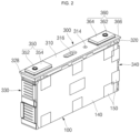
- FIG. 2 is a perspective view of a cap assembly and an electrode assembly of the secondary battery shown in FIG. 1 .
- FIG. 3 is a perspective view illustrating a part of a current collecting structure shown in FIG. 2 .
- a direction of an upper portion is defined as an upward direction
- a direction of a lower portion is defined as a downward direction.
- a secondary battery 10 may include an electrode assembly 100, a case 200 accommodating the electrode assembly 100, and a cap assembly 300 coupled to the case 200.
- the secondary battery 10 may be a prismatic battery in which the case 200 has a rectangular parallelepiped shape.
- this is merely an example, and the present disclosure can be applied to various types of secondary batteries.
- the electrode assembly 100 may be formed by winding or stacking a plurality of unit stacks, each of which include a first electrode plate 110 and a second electrode plate 120 in the form of thin plates or films with a separator 130 interposed therebetween (see, e.g., FIG. 4 ).
- a winding shaft may be disposed in a horizontal direction approximately parallel to a length direction of the cap assembly 300 or in a vertical direction approximately perpendicular to the length direction of the cap assembly 300.
- long side surfaces of the plurality of unit stacks may be disposed adjacent to each other.
- a sheet 140 made of an insulating material may be attached to an outer portion of the electrode assembly 100 by an insulating tape 150 to insulate the electrode assembly 100 from the case 200.
- the first electrode plate 110 may be a negative electrode
- the second electrode plate 120 may be a positive electrode.
- the first electrode plate 110 may be a positive electrode
- the second electrode plate 120 may be a negative electrode.
- the first electrode plate 110 When the first electrode plate 110 is a negative electrode plate, the first electrode plate 110 may be formed by applying a first electrode active material, such as graphite or carbon, on a first electrode current collector provided as a metal foil made of copper, a copper alloy, nickel, or a nickel alloy.
- the first electrode plate 110 may have a first uncoated portion, which is a region of the first electrode current collector on which the first electrode active material is not applied. Because the first uncoated portion acts as a tab electrically connected to a first collector plate 330, to be described below, the first uncoated portion may be defined as (or referred to as) a first substrate tab.
- a plurality of first substrate tabs may be bent to one side (e.g., may be bent in one direction) and welded to the first collector plate 330.
- the first collector plate 330 may be electrically connected to the cap assembly 300.
- the second electrode plate 120 may be formed by applying a second active material, such as a transition metal oxide, on a second electrode current collector provided as a metal foil made of copper, a copper alloy, nickel, or a nickel alloy.
- the second electrode plate 120 may have a second uncoated portion 122 (see, e.g., FIG. 4 ), which is a region of the second electrode current collector on which the second electrode active material is not applied. Because the second uncoated portion 122 acts as a tab electrically connected to a second collector plate 340, to be described below, the second uncoated portion 122 may be defined as (or may be referred to as) a second substrate tab.
- a plurality of second substrate tabs may be bent to one side (e.g., may be bent in one direction) and welded to the second collector plate 340.
- the second collector plate 340 may be electrically connected to the cap assembly 300.
- the separator 130 is disposed between the first electrode plate 110 and the second electrode plate 120 to prevent a short circuit therebetween while enabling the movement of lithium ions therebetween.
- the separator 130 may include polyethylene, polypropylene, or a composite film of polyethylene and polypropylene.
- the present disclosure is not limited to the above materials.
- the electrode assembly 100 and an electrolyte may be accommodated in the case 200.
- the electrolyte may include a lithium salt, such as LiPF 6 or LiBF 4 , in an organic solvent, such as ethylene carbonate (EC), propylene carbonate (PC), diethyl carbonate (DEC), ethyl methyl carbonate (EMC), or dimethyl carbonate (DMC).
- the electrolyte may be in a liquid or gel state. In some embodiments, when an inorganic-based solid electrolyte is used, the liquid or gel electrolyte may be omitted.
- the case 200 may have an approximately rectangular parallelepiped box shape with an open upper portion thereof in a length direction and an accommodation space formed therein.
- the electrode assembly 100 and the electrolyte may be accommodated inside the case 200 through the open upper portion.
- Some components of the cap assembly 300 may be exposed to the outside of the case 200, and some components thereof may be accommodated inside the case 200.
- the case 200 may have a bottom surface 210 having a rectangular shape and four side surfaces connected to (e.g., extending from) the bottom surface 210. Among the side surfaces, a surface having a relatively large area is defined as a long side portion 220, and a surface having a relatively small area is defined as a short side portion 230.
- the electrode assembly 100 may be disposed such that a plate surface (e.g., a large, flat surface) thereof faces the long side portion 220.
- the cap assembly 300 is coupled to the case 200 and electrically connected to the electrode assembly 100.
- the cap assembly 300 may include a cap plate 310 coupled to the case 200, a plurality of insulating members, the first collector plate 330, the second collector plate 340, a first terminal 350, and a second terminal 360.
- a cap plate 310 coupled to the case 200
- a plurality of insulating members the first collector plate 330, the second collector plate 340
- a first terminal 350 the first terminal 355
- a second terminal 360 the cap assembly 300 may include a cap plate 310 coupled to the case 200, a plurality of insulating members, the first collector plate 330, the second collector plate 340, a first terminal 350, and a second terminal 360.
- the cap plate 310 may have an approximately rectangular plate shape and may be made of the same material as the case 200.
- the cap plate 310 may have terminal holes (e.g., terminal openings) for coupling with the first terminal 350 and the second terminal 360, an injection hole (e.g., an injection opening) 314, and a vent hole (e.g., a vent opening) for coupling with a vent 316.
- the plurality of insulating members, including an insulating plate 320, may be provided to insulate the cap plate 310 from the electrode assembly 100.
- the first collector plate 330 electrically connects the first electrode plate 110 via the first substrate tab.
- the first collector plate 330 electrically connects the first electrode plate 110, which may be the negative electrode plate, and the first terminal 350.
- the first collector plate 330 may be made of the same material as the first electrode plate 110.
- the first collector plate 330 may have an approximately rectangular shape.
- the first collector plate 330 may have a concave-convex shape bent such that an approximately central portion thereof in a length direction protrudes outwardly (herein after called protruding portion).
- the first collector plate 330 may have a shape in which both plate shapes with respect to the outwardly protruding central portion are bent toward the electrode assembly 100.
- surfaces excluding the outwardly protruding central portion and outwardly protruding ends of the first collector plate 330 are defined as welding region (welding surfaces).
- Upper and lower surfaces of the first collector plate 330 may be welded except for the outwardly protruding central portion (protruding portion).
- the first collector plate 330 may be electrically connected to the first substrate tab of the first electrode plate 110 by laser welding. After the first substrate tabs are gathered to one side for welding, the first collector plate 330 may be placed on the first substrate tabs, and end portions thereof may be bent on the first collector plate 330 and then laser welding may be performed.
- the second collector plate 340 is disposed symmetrically with the first collector plate 330 and is electrically connected to the second electrode plate 120.
- the first collector plate 330 is electrically connected to the second electrode plate 120 via the second substrate tab 122.
- the second collector plate 340 may be made of the same material as the second substrate tab of the second electrode plate 120.
- the second collector plate 340 may have the same shape as the first collector plate 330 and may be disposed symmetrically with the first collector plate 330.
- a surface of the second collector plate 340 to be welded is also defined as a welding region 342 (welding surface) for convenience.
- the second collector plate 340 may be placed on the second substrate tabs 122, end portions thereof may be bent on the second collector plate 340 and, then, laser welding may be performed.
- a welding region 342 at where laser welding is performed may be a plate surface of a current collector plate (see, e.g., region A in FIG. 3 ).
- the first terminal 350 may include a first terminal pin 352 and a first terminal plate 354.
- the first terminal plate 354 may be insulated from the cap plate 310 by an insulating member 328.
- the first terminal pin 352 is electrically connected to the first collector plate 330 and is electrically connected to the first electrode plate 110 of the electrode assembly 100.
- the second terminal 360 may include a second terminal pin 362, a second terminal plate 364, and a conductive plate 366.
- the second terminal 360 is disposed symmetrically with the first terminal 350.
- the conductive plate 366 electrically connects the cap plate 310 and the second terminal plate 364, which is electrically connected to the second terminal pin 362.
- the cap plate 310 may be electrically connected to the second electrode plate 120. Accordingly, the cap plate 310 has the same positive polarity as the second collector plate 340, and the case 200 welded to the cap plate 310 also has positive polarity.
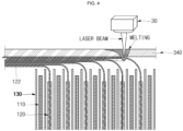
- FIG. 4 illustrates a welding method based on a second substrate tab 122 of a second electrode plate 120, but the same welding method can be applied to a first electrode plate 110 and a first substrate tab.
- FIG. 4 is a cross-sectional view illustrating a welding method according to an embodiment of the present disclosure.
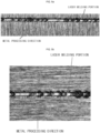
- FIGS. 5a and 5b are photographs showing a laser welding portion as a result of processing a metal of a current collector plate according to an embodiment of the present disclosure.
- the direction of the laser welding portion is perpendicular to metal processing direction of the current collector plate.
- the direction of the laser welding portion is parallel to the metal processing direction of the current collector plate.
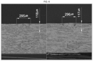
- FIG. 6 are photographs showing the orientation of metal grains according to a laser welding direction as a result of processing (e.g. by rolling-processing) a metal of a current collector plate, such as the first current collector plate 330 or second current collector plate 340.
- FIG. 5a and 5b are photographs showing a laser welding portion as a result of processing (e.g. by rolling-processing) a metal of a current collector plate, such as the first current collector plate 330 or second current collector plate 340.
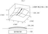
- FIG. 7 is a view illustrating a current collector plate according to another embodiment when a welding method according to an embodiment of the present disclosure is applied.
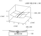
- FIG. 8 is a view illustrating a negative example of a current collector plate when the welding method according to an embodiment of the present disclosure is not applied.
- welding between an electrode assembly 100 and a second collector plate 340 may be performed through laser welding.
- the second substrate tabs 122 are gathered to one side, and the second current collector plate 340 may be lifted and may be pressed against the second substrate tabs 122 and fixed with a jig or the like.
- a laser beam is radiated by a laser welding device 30 to melt the second current collector plate 340.
- a rear surface of the second current collector plate 340 is partially melted so that the second current collector plate 340 and the second substrate tabs 122 are welded together.
- a rear surface of the second current collector plate 340 is partially melted to form a back (welding) bead, so that the second current collector plate 340 and the second substrate tabs 122 are welded together to form a laser welding portion 348 in the welding region 342.
- a metal plate, such as a current collector plate, is processed to have a certain shape and thickness through a rolling process or the like, and as shown in, for example, FIGS. 5a and 5b , a processing direction (hereinafter defined as a "metal processing direction") is generated on a surface of the metal plate.
- a processing direction hereinafter defined as a "metal processing direction”
- the direction of the manufacturing processing of the (metal) current collector plate causes the current collector plate to have a (uniformly) oriented material structure (herein called metal processing direction).
- a laser welding portion 348 is perpendicular or parallel to a metal processing direction or has a certain angle with respect to the metal processing direction.
- the laser welding portion corresponds to a linear laser welding line.
- the laser welding portion may be a linear welding seam.
- the welding regions 342 may be a plurality of laser welding portions 348 (e.g. linear welding seams).
- the (linear) laser welding portion 348 may be parallel to a metal processing direction or has a certain angle with respect to the metal processing direction.
- a laser welding portion 348 may be perpendicular to a metal processing direction or a laser welding portion may be parallel to a metal processing direction, as shown in FIG. 6 .
- the left side of FIG. 6 shows a state B of metal grains of a cross section of a collector plate when a laser welding portion is formed in a direction parallel to a metal processing direction (corresponding to FIG. 5b ).
- the right side of FIG. 6 shows a state C of metal grains of a cross section of a collector plate when a laser welding portion is formed in a direction perpendicular to a metal processing direction (corresponding to FIG. 5a ).
- B and C grains direction of the cross sections of the collector plates are different due to a difference in rolling direction.
- sizes and depths of the welding portions to be melted are also different. That is, when a laser welding portion is formed parallel to a metal processing direction, a melted portion is narrower and deeper. In this case, a degree of unevenness of a metal surface according to a welding direction is less than that of a case in which a laser welding portion is perpendicular to a metal processing direction. Accordingly, an amount of generated spatter can be reduced, and welding stability can be improved.
- the first and second current collector plates 330 and 340 may damage the electrode assembly. Therefore, the laser welding being performed parallel to a metal processing direction is an optimal direction in which weldability is improved and the electrode assembly is not damaged. In the past, during laser welding, welding has been performed without consideration for a metal processing direction. However, according to embodiments of the present disclosure, because a laser welding direction is determined in consideration of a metal processing direction, welding quality is improved.
- a laser welding direction is arranged, thereby reducing or minimizing the occurrence of spatter. Because such arrangement is performed in consideration of deformation after welding, cell damage due to contact between a current collector and a separator may be prevented.
- a secondary battery may include: an electrode assembly, a case accommodating the electrode assembly; and a cap assembly sealing the case and including a pair of current collector plates.
- the electrode assembly may include a first electrode plate having a first substrate tab extending in one direction, a second electrode plate having a second substrate tab extending in another direction, and a separator interposed between the first electrode plate and the second electrode plate.
- Each of the current collector plates may be electrically connected to one of the first substrate tab and the second substrate tab.
- the current collector plates may be laser-welded to the first substrate tab and the second substrate tab, respectively, and a laser welding direction may be parallel to a metal processing direction of the corresponding current collector plate.
Landscapes
- Chemical & Material Sciences (AREA)
- Chemical Kinetics & Catalysis (AREA)
- Electrochemistry (AREA)
- General Chemical & Material Sciences (AREA)
- Engineering & Computer Science (AREA)
- Physics & Mathematics (AREA)
- Optics & Photonics (AREA)
- Manufacturing & Machinery (AREA)
- Plasma & Fusion (AREA)
- Mechanical Engineering (AREA)
- Connection Of Batteries Or Terminals (AREA)
Applications Claiming Priority (1)
| Application Number | Priority Date | Filing Date | Title |
|---|---|---|---|
| KR1020220148482A KR20240067469A (ko) | 2022-11-09 | 2022-11-09 | 이차전지 |
Publications (2)
| Publication Number | Publication Date |
|---|---|
| EP4375004A1 true EP4375004A1 (fr) | 2024-05-29 |
| EP4375004B1 EP4375004B1 (fr) | 2026-03-25 |
Family
ID=88689706
Family Applications (1)
| Application Number | Title | Priority Date | Filing Date |
|---|---|---|---|
| EP23207468.2A Active EP4375004B1 (fr) | 2022-11-09 | 2023-11-02 | Batterie secondaire et procédé de fabrication de cette batterie secondaire |
Country Status (4)
| Country | Link |
|---|---|
| US (1) | US20240154258A1 (fr) |
| EP (1) | EP4375004B1 (fr) |
| KR (1) | KR20240067469A (fr) |
| CN (1) | CN118016956A (fr) |
Families Citing this family (4)
| Publication number | Priority date | Publication date | Assignee | Title |
|---|---|---|---|---|
| KR20250116891A (ko) * | 2024-01-26 | 2025-08-04 | 삼성에스디아이 주식회사 | 이차전지 |
| KR20260019116A (ko) * | 2024-08-01 | 2026-02-10 | 주식회사 엘지에너지솔루션 | 이차 전지 및 그의 제조 방법 |
| US20260051632A1 (en) * | 2024-08-13 | 2026-02-19 | Lg Energy Solution, Ltd. | Secondary Battery and Method of Manufacturing the Same |
| CN118752071B (zh) * | 2024-09-02 | 2024-11-15 | 广汽埃安新能源汽车股份有限公司 | 多层集流体的焊接方法及设备 |
Citations (3)
| Publication number | Priority date | Publication date | Assignee | Title |
|---|---|---|---|---|
| US20130252053A1 (en) * | 2012-03-20 | 2013-09-26 | Samsung Sdi Co., Ltd. | Secondary battery |
| EP3451417A1 (fr) * | 2017-08-31 | 2019-03-06 | Samsung SDI Co., Ltd. | Batterie secondaire |
| EP4037048A1 (fr) * | 2019-09-26 | 2022-08-03 | SANYO Electric Co., Ltd. | Batterie secondaire et son procédé de fabrication |
Family Cites Families (1)
| Publication number | Priority date | Publication date | Assignee | Title |
|---|---|---|---|---|
| KR102884472B1 (ko) * | 2019-11-07 | 2025-11-11 | 삼성에스디아이 주식회사 | 이차 전지 |
-
2022
- 2022-11-09 KR KR1020220148482A patent/KR20240067469A/ko active Pending
-
2023
- 2023-09-20 US US18/471,028 patent/US20240154258A1/en active Pending
- 2023-11-02 EP EP23207468.2A patent/EP4375004B1/fr active Active
- 2023-11-09 CN CN202311486574.XA patent/CN118016956A/zh active Pending
Patent Citations (3)
| Publication number | Priority date | Publication date | Assignee | Title |
|---|---|---|---|---|
| US20130252053A1 (en) * | 2012-03-20 | 2013-09-26 | Samsung Sdi Co., Ltd. | Secondary battery |
| EP3451417A1 (fr) * | 2017-08-31 | 2019-03-06 | Samsung SDI Co., Ltd. | Batterie secondaire |
| EP4037048A1 (fr) * | 2019-09-26 | 2022-08-03 | SANYO Electric Co., Ltd. | Batterie secondaire et son procédé de fabrication |
Non-Patent Citations (1)
| Title |
|---|
| JOHN C. ION: "Laser processing of engineering materials", REFEREX, 31 December 2005 (2005-12-31), pages 1 - 589, XP040425979 * |
Also Published As
| Publication number | Publication date |
|---|---|
| US20240154258A1 (en) | 2024-05-09 |
| KR20240067469A (ko) | 2024-05-17 |
| EP4375004B1 (fr) | 2026-03-25 |
| CN118016956A (zh) | 2024-05-10 |
Similar Documents
| Publication | Publication Date | Title |
|---|---|---|
| EP4375004A1 (fr) | Batterie secondaire et procédé de fabrication de cette batterie secondaire | |
| EP3709392B1 (fr) | Batterie secondaire | |
| US20240154267A1 (en) | Secondary battery | |
| US20250046969A1 (en) | Secondary battery | |
| KR102769119B1 (ko) | 이차 전지 | |
| US20240304947A1 (en) | Secondary battery | |
| US20110076544A1 (en) | Stack type battery | |
| EP4366070A2 (fr) | Batterie secondaire avec ensemble d'électrode soudé | |
| US8614015B2 (en) | Secondary battery and method of manufacturing secondary battery | |
| KR20170109968A (ko) | 이차 전지 | |
| CN113875043B (zh) | 二次电池 | |
| KR20230049795A (ko) | 이차 전지 | |
| EP4471970A1 (fr) | Batterie secondaire | |
| KR20230013599A (ko) | 파우치형 이차전지 및 이의 제조방법 | |
| US20250192388A1 (en) | Secondary battery | |
| EP4213280A1 (fr) | Batterie secondaire | |
| KR20220139676A (ko) | 이차전지 | |
| US20250105408A1 (en) | Secondary battery | |
| US20250316798A1 (en) | Secondary battery | |
| US20250070408A1 (en) | Secondary battery | |
| US20250070339A1 (en) | Secondary battery | |
| US20250087834A1 (en) | Electrode assembly and rechargeable battery including the same | |
| US20260051633A1 (en) | Secondary Battery and Manufacturing Method Thereof | |
| KR20260034495A (ko) | 전극 조립체 및 이를 포함한 이차 전지 | |
| KR20260024605A (ko) | 이차 전지 및 이차 전지 제조 방법 |
Legal Events
| Date | Code | Title | Description |
|---|---|---|---|
| PUAI | Public reference made under article 153(3) epc to a published international application that has entered the european phase |
Free format text: ORIGINAL CODE: 0009012 |
|
| STAA | Information on the status of an ep patent application or granted ep patent |
Free format text: STATUS: REQUEST FOR EXAMINATION WAS MADE |
|
| 17P | Request for examination filed |
Effective date: 20231102 |
|
| AK | Designated contracting states |
Kind code of ref document: A1 Designated state(s): AL AT BE BG CH CY CZ DE DK EE ES FI FR GB GR HR HU IE IS IT LI LT LU LV MC ME MK MT NL NO PL PT RO RS SE SI SK SM TR |
|
| GRAP | Despatch of communication of intention to grant a patent |
Free format text: ORIGINAL CODE: EPIDOSNIGR1 |
|
| STAA | Information on the status of an ep patent application or granted ep patent |
Free format text: STATUS: GRANT OF PATENT IS INTENDED |
|
| RIC1 | Information provided on ipc code assigned before grant |
Ipc: B23K 26/244 20140101AFI20251122BHEP Ipc: B23K 101/38 20060101ALI20251122BHEP Ipc: H01M 50/528 20210101ALI20251122BHEP Ipc: H01M 50/536 20210101ALI20251122BHEP Ipc: H01M 50/538 20210101ALI20251122BHEP Ipc: H01M 50/54 20210101ALI20251122BHEP Ipc: H01M 50/15 20210101ALI20251122BHEP Ipc: H01M 50/176 20210101ALI20251122BHEP Ipc: H01M 50/533 20210101ALI20251122BHEP Ipc: H01M 50/534 20210101ALI20251122BHEP Ipc: H01M 10/0587 20100101ALI20251122BHEP |
|
| INTG | Intention to grant announced |
Effective date: 20251222 |
|
| RIN1 | Information on inventor provided before grant (corrected) |
Inventor name: YEO, HA RAM Inventor name: HWANG, IN HYUN Inventor name: KIM, BUM RAE |
|
| GRAS | Grant fee paid |
Free format text: ORIGINAL CODE: EPIDOSNIGR3 |
|
| GRAA | (expected) grant |
Free format text: ORIGINAL CODE: 0009210 |
|
| STAA | Information on the status of an ep patent application or granted ep patent |
Free format text: STATUS: THE PATENT HAS BEEN GRANTED |
|
| AK | Designated contracting states |
Kind code of ref document: B1 Designated state(s): AL AT BE BG CH CY CZ DE DK EE ES FI FR GB GR HR HU IE IS IT LI LT LU LV MC ME MK MT NL NO PL PT RO RS SE SI SK SM TR |
|
| REG | Reference to a national code |
Ref country code: CH Ref legal event code: F10 Free format text: ST27 STATUS EVENT CODE: U-0-0-F10-F00 (AS PROVIDED BY THE NATIONAL OFFICE) Effective date: 20260325 Ref country code: GB Ref legal event code: FG4D |
|
| REG | Reference to a national code |
Ref country code: DE Ref legal event code: R096 Ref document number: 602023014007 Country of ref document: DE |
|
| REG | Reference to a national code |
Ref country code: IE Ref legal event code: FG4D |