EP4375186A2 - Systèmes et procédés de surveillance de l'état de santé pour servovalves - Google Patents
Systèmes et procédés de surveillance de l'état de santé pour servovalves Download PDFInfo
- Publication number
- EP4375186A2 EP4375186A2 EP24170296.8A EP24170296A EP4375186A2 EP 4375186 A2 EP4375186 A2 EP 4375186A2 EP 24170296 A EP24170296 A EP 24170296A EP 4375186 A2 EP4375186 A2 EP 4375186A2
- Authority
- EP
- European Patent Office
- Prior art keywords
- brake controller
- phase shift
- health monitoring
- brake
- servo valve
- Prior art date
- Legal status (The legal status is an assumption and is not a legal conclusion. Google has not performed a legal analysis and makes no representation as to the accuracy of the status listed.)
- Granted
Links
Images


Classifications
-
- B—PERFORMING OPERATIONS; TRANSPORTING
- B60—VEHICLES IN GENERAL
- B60T—VEHICLE BRAKE CONTROL SYSTEMS OR PARTS THEREOF; BRAKE CONTROL SYSTEMS OR PARTS THEREOF, IN GENERAL; ARRANGEMENT OF BRAKING ELEMENTS ON VEHICLES IN GENERAL; PORTABLE DEVICES FOR PREVENTING UNWANTED MOVEMENT OF VEHICLES; VEHICLE MODIFICATIONS TO FACILITATE COOLING OF BRAKES
- B60T17/00—Component parts, details, or accessories of power brake systems not covered by groups B60T8/00, B60T13/00 or B60T15/00, or presenting other characteristic features
- B60T17/18—Safety devices; Monitoring
- B60T17/22—Devices for monitoring or checking brake systems; Signal devices
- B60T17/221—Procedure or apparatus for checking or keeping in a correct functioning condition of brake systems
-
- B—PERFORMING OPERATIONS; TRANSPORTING
- B60—VEHICLES IN GENERAL
- B60T—VEHICLE BRAKE CONTROL SYSTEMS OR PARTS THEREOF; BRAKE CONTROL SYSTEMS OR PARTS THEREOF, IN GENERAL; ARRANGEMENT OF BRAKING ELEMENTS ON VEHICLES IN GENERAL; PORTABLE DEVICES FOR PREVENTING UNWANTED MOVEMENT OF VEHICLES; VEHICLE MODIFICATIONS TO FACILITATE COOLING OF BRAKES
- B60T8/00—Arrangements for adjusting wheel-braking force to meet varying vehicular or ground-surface conditions, e.g. limiting or varying distribution of braking force
- B60T8/17—Using electrical or electronic regulation means to control braking
- B60T8/1701—Braking or traction control means specially adapted for particular types of vehicles
- B60T8/1703—Braking or traction control means specially adapted for particular types of vehicles for aircrafts
-
- B—PERFORMING OPERATIONS; TRANSPORTING
- B60—VEHICLES IN GENERAL
- B60T—VEHICLE BRAKE CONTROL SYSTEMS OR PARTS THEREOF; BRAKE CONTROL SYSTEMS OR PARTS THEREOF, IN GENERAL; ARRANGEMENT OF BRAKING ELEMENTS ON VEHICLES IN GENERAL; PORTABLE DEVICES FOR PREVENTING UNWANTED MOVEMENT OF VEHICLES; VEHICLE MODIFICATIONS TO FACILITATE COOLING OF BRAKES
- B60T13/00—Transmitting braking action from initiating means to ultimate brake actuator with power assistance or drive; Brake systems incorporating such transmitting means, e.g. air-pressure brake systems
- B60T13/10—Transmitting braking action from initiating means to ultimate brake actuator with power assistance or drive; Brake systems incorporating such transmitting means, e.g. air-pressure brake systems with fluid assistance, drive, or release
- B60T13/66—Electrical control in fluid-pressure brake systems
- B60T13/662—Electrical control in fluid-pressure brake systems characterised by specified functions of the control system components
-
- B—PERFORMING OPERATIONS; TRANSPORTING
- B60—VEHICLES IN GENERAL
- B60T—VEHICLE BRAKE CONTROL SYSTEMS OR PARTS THEREOF; BRAKE CONTROL SYSTEMS OR PARTS THEREOF, IN GENERAL; ARRANGEMENT OF BRAKING ELEMENTS ON VEHICLES IN GENERAL; PORTABLE DEVICES FOR PREVENTING UNWANTED MOVEMENT OF VEHICLES; VEHICLE MODIFICATIONS TO FACILITATE COOLING OF BRAKES
- B60T17/00—Component parts, details, or accessories of power brake systems not covered by groups B60T8/00, B60T13/00 or B60T15/00, or presenting other characteristic features
- B60T17/18—Safety devices; Monitoring
- B60T17/22—Devices for monitoring or checking brake systems; Signal devices
-
- B—PERFORMING OPERATIONS; TRANSPORTING
- B60—VEHICLES IN GENERAL
- B60T—VEHICLE BRAKE CONTROL SYSTEMS OR PARTS THEREOF; BRAKE CONTROL SYSTEMS OR PARTS THEREOF, IN GENERAL; ARRANGEMENT OF BRAKING ELEMENTS ON VEHICLES IN GENERAL; PORTABLE DEVICES FOR PREVENTING UNWANTED MOVEMENT OF VEHICLES; VEHICLE MODIFICATIONS TO FACILITATE COOLING OF BRAKES
- B60T8/00—Arrangements for adjusting wheel-braking force to meet varying vehicular or ground-surface conditions, e.g. limiting or varying distribution of braking force
- B60T8/17—Using electrical or electronic regulation means to control braking
- B60T8/171—Detecting parameters used in the regulation; Measuring values used in the regulation
-
- B—PERFORMING OPERATIONS; TRANSPORTING
- B60—VEHICLES IN GENERAL
- B60T—VEHICLE BRAKE CONTROL SYSTEMS OR PARTS THEREOF; BRAKE CONTROL SYSTEMS OR PARTS THEREOF, IN GENERAL; ARRANGEMENT OF BRAKING ELEMENTS ON VEHICLES IN GENERAL; PORTABLE DEVICES FOR PREVENTING UNWANTED MOVEMENT OF VEHICLES; VEHICLE MODIFICATIONS TO FACILITATE COOLING OF BRAKES
- B60T8/00—Arrangements for adjusting wheel-braking force to meet varying vehicular or ground-surface conditions, e.g. limiting or varying distribution of braking force
- B60T8/18—Arrangements for adjusting wheel-braking force to meet varying vehicular or ground-surface conditions, e.g. limiting or varying distribution of braking force responsive to vehicle weight or load, e.g. load distribution
-
- B—PERFORMING OPERATIONS; TRANSPORTING
- B60—VEHICLES IN GENERAL
- B60T—VEHICLE BRAKE CONTROL SYSTEMS OR PARTS THEREOF; BRAKE CONTROL SYSTEMS OR PARTS THEREOF, IN GENERAL; ARRANGEMENT OF BRAKING ELEMENTS ON VEHICLES IN GENERAL; PORTABLE DEVICES FOR PREVENTING UNWANTED MOVEMENT OF VEHICLES; VEHICLE MODIFICATIONS TO FACILITATE COOLING OF BRAKES
- B60T8/00—Arrangements for adjusting wheel-braking force to meet varying vehicular or ground-surface conditions, e.g. limiting or varying distribution of braking force
- B60T8/32—Arrangements for adjusting wheel-braking force to meet varying vehicular or ground-surface conditions, e.g. limiting or varying distribution of braking force responsive to a speed condition, e.g. acceleration or deceleration
- B60T8/321—Arrangements for adjusting wheel-braking force to meet varying vehicular or ground-surface conditions, e.g. limiting or varying distribution of braking force responsive to a speed condition, e.g. acceleration or deceleration deceleration
- B60T8/325—Systems specially adapted for aircraft
-
- B—PERFORMING OPERATIONS; TRANSPORTING
- B64—AIRCRAFT; AVIATION; COSMONAUTICS
- B64C—AEROPLANES; HELICOPTERS
- B64C25/00—Alighting gear
- B64C25/32—Alighting gear characterised by elements which contact the ground or similar surface
- B64C25/42—Arrangement or adaptation of brakes
-
- B—PERFORMING OPERATIONS; TRANSPORTING
- B60—VEHICLES IN GENERAL
- B60T—VEHICLE BRAKE CONTROL SYSTEMS OR PARTS THEREOF; BRAKE CONTROL SYSTEMS OR PARTS THEREOF, IN GENERAL; ARRANGEMENT OF BRAKING ELEMENTS ON VEHICLES IN GENERAL; PORTABLE DEVICES FOR PREVENTING UNWANTED MOVEMENT OF VEHICLES; VEHICLE MODIFICATIONS TO FACILITATE COOLING OF BRAKES
- B60T2240/00—Monitoring, detecting wheel/tyre behaviour; counteracting thereof
- B60T2240/06—Wheel load; Wheel lift
-
- B—PERFORMING OPERATIONS; TRANSPORTING
- B60—VEHICLES IN GENERAL
- B60T—VEHICLE BRAKE CONTROL SYSTEMS OR PARTS THEREOF; BRAKE CONTROL SYSTEMS OR PARTS THEREOF, IN GENERAL; ARRANGEMENT OF BRAKING ELEMENTS ON VEHICLES IN GENERAL; PORTABLE DEVICES FOR PREVENTING UNWANTED MOVEMENT OF VEHICLES; VEHICLE MODIFICATIONS TO FACILITATE COOLING OF BRAKES
- B60T2270/00—Further aspects of brake control systems not otherwise provided for
- B60T2270/40—Failsafe aspects of brake control systems
- B60T2270/406—Test-mode; Self-diagnosis
-
- B—PERFORMING OPERATIONS; TRANSPORTING
- B64—AIRCRAFT; AVIATION; COSMONAUTICS
- B64D—EQUIPMENT FOR FITTING IN OR TO AIRCRAFT; FLIGHT SUITS; PARACHUTES; ARRANGEMENT OR MOUNTING OF POWER PLANTS OR PROPULSION TRANSMISSIONS IN AIRCRAFT
- B64D45/00—Aircraft indicators or protectors not otherwise provided for
- B64D2045/0085—Devices for aircraft health monitoring, e.g. monitoring flutter or vibration
Definitions
- the present disclosure relates to control systems and methods for health monitoring servo valve frequency response for aircraft brakes prior to flight.
- servo valves may experience performance degradation in frequency characteristics due to wear and tear, as well as operating in brake fluid that becomes dirtier over time. Particles may cause slip inside a sleeve/spool assembly and lower a servo valve performance, causing a change in static and dynamic characteristics of servo valves. The control of servo valves may degrade in response to these changes in static and dynamic characteristics causing oscillations due to the coupling of the control characteristics and servo valve dynamics.
- a system for performing frequency response health monitoring of a servo valve prior to flight of an aircraft may comprise: the servo valve; and a brake controller in electrical communication with the servo valve, the brake controller configured to: determine the brake controller is powering up, supply a variable current to the servo valve to perform the frequency response health monitoring to the servo valve in response to determining the brake controller is powering up, and determine a health status of the servo valve based on the frequency response health monitoring.
- the brake controller may be further configured to calculate an average phase shift over a predetermined time period in response to supplying the variable current to the servo valve.
- the brake controller may be further configured to compare the average phase shift to a phase shift threshold.
- the brake controller may be further configured to count a number of phase shift exceedances over a plurality of brake controller power cycles.
- the brake controller may be further configured to generate a message indicating a service will be needed soon to an indicator.
- the system may further comprise a first throttle and a second throttle, wherein the brake controller is further configured to determine both the first throttle and the second throttle are not in a forward position prior to performing the frequency response health monitoring.
- the system may further comprise a weight on wheels sensor, wherein the brake controller is configured to receive a measurement from the weight on wheels sensor and determine whether the aircraft is grounded.
- a method of performing a frequency response health monitoring for a servo valve of a braking system is disclosed herein.
- the method may comprise: receiving, via a brake controller, a first indication whether an aircraft is grounded and not moving; receiving, via the brake controller, a second indication whether braking is being applied to the braking system; supplying, via the brake controller, a variable current to the servo valve in response to the first indication being true and the second indication being false; comparing, via the brake controller, an average phase shift over a predetermined period of time to a predetermined phase shift threshold; and determining, via the brake controller, whether the average phase shift exceeds the predetermined phase shift threshold.
- the method may further comprise determining, via the brake controller, the brake controller is powering up.
- the first indication and the second indication may be received in response to the brake controller powering up.
- Receiving the first indication may further comprise receiving, via the brake controller, a throttle indicator indicating a throttle is not forward and a weight on wheels indicator indicating there is a weight on a wheel for a main landing gear.
- the method may further comprise counting, via the brake controller, a number of continuous phase shift exceedances over a plurality of brake controller power cycles.
- the method may further comprise determining, via the brake controller, the number of continuous phase shift exceedances over the plurality of brake controller power cycles exceeds a predetermined threshold of phase shift exceedances.
- the method may further comprise generating, via the brake controller, a service message in response to the number of continuous phase shift exceedances exceeding the predetermined threshold of phase shift exceedances.
- a method of determining a service valve health status is disclosed herein.
- the method may comprise: performing, via a brake controller, a plurality of frequency response health monitoring tests for a servo valve; supplying, via the brake controller, a variable current to the servo valve for each frequency response health monitoring test in the plurality of frequency response health monitoring tests; and comparing, via the brake controller, a phase shift over a predetermined period of time to a predetermined phase shift threshold.
- the method may further comprise in response to the phase shift exceeding the predetermined phase shift threshold: counting, via the brake controller, a number of continuous phase shift exceedances.
- the method may further comprise generating, via the brake controller, a service message in response to the number of continuous phase shift exceedances exceeding a predetermined number of continuous phase shift exceedances.
- Each test in the plurality of frequency response health monitoring tests are performed in response to the brake controller determining the brake controller is powering up.
- Each test in the plurality of frequency response health monitoring tests may be performed for a respective power cycle of the brake controller.
- the method may further comprise determining, via the brake controller, whether the phase shift exceeds the predetermined phase shift threshold.
- an aircraft 100 in accordance with various embodiments can include multiple landing gear including a first landing gear 110, a second landing gear 120, and a third landing gear 130.
- Each landing gear may include one or more wheel assemblies.
- the third landing gear 130 includes an inner wheel assembly 132 and an outer wheel assembly 134.
- the aircraft 100 may further include one or more brake coupled to each wheel assembly.
- a first brake 140 may be coupled to the inner wheel assembly 132
- a second brake 142 may be coupled to the outer wheel assembly 134.
- the first brake 140 may apply a braking force to the inner wheel assembly 132 upon receiving a brake command.
- the second brake 142 may apply a braking force to the outer wheel assembly 134 upon receiving a brake command.
- multiple brakes may apply a braking force to the inner wheel assembly 132.
- the aircraft 100 may further include a brake control unit (BCU) or brake controller 150.
- the brake controller 150 may include one or more processors and one or more tangible, non-transitory memories and be capable of implementing logic.
- the processor can be a general purpose processor, a digital signal processor (DSP), an application specific integrated circuit (ASIC), a field programmable gate array (FPGA) or other programmable logic device, discrete gate or transistor logic, discrete hardware components, or any combination thereof.
- the brake controller 150 may be specifically designed for controlling operation of aircraft brakes.
- the brake controller 150 may control operation of the first brake 140 and the second brake 142 under normal operating conditions.
- the aircraft 100 may further include one or more gas turbine engine 160.
- the gas turbine engine 160 may be controlled by a pilot (such as by controlling a throttle 212 in a cockpit) to generate thrust to accelerate the aircraft 100.
- a system 200 may be used to monitor servo valve health of an aircraft brake system prior to flight of the aircraft, is illustrated in accordance with various embodiments.
- the servo valve health monitoring may be performed automatically.
- the system 200 may be implemented in an aircraft such as the aircraft 100 of FIG. 1 .
- the system 200 may include one or more landing gear 202 that includes one or more wheel or wheel assembly 204.
- the system 200 may further include an actuator 250 fluidly coupled to a servo valve 252 and a shut off valve 254.
- the actuator 250 is designed to apply force to a brake assembly in response to a hydraulic pressure being provided to the actuator 250 via the servo valve 252, which may in turn apply torque to, and reduce rotational velocity of, the wheel assembly 204.
- the system 200 may also include a brake controller 208 designed to control operation of the servo valve 252.
- the system 200 may further include a sensor 210 designed to detect whether the aircraft is on the ground.
- the sensor 210 may include a weight on wheels (WoW) sensor coupled to the landing gear 202 and configured to detect a force on wheel assembly 204 to signify the aircraft (e.g., aircraft 100) is on the ground and provide an input to the brake controller 208.
- WoW weight on wheels
- the sensor 210 is not limited in this regard.
- the system 200 may further include a gas turbine engine 216, a throttle 212, and a braking input device 214.
- the engine 216 may generate thrust to propel a corresponding aircraft.
- the throttle 212 may include an input device, such as a joystick or other input device, which may be used to request power from the engine 216. For example, a pilot may use the throttle 212 to request thrust from the engine 216.
- the braking input device 214 may include an input device which may be used to manually control braking of the brake 206.
- the braking input device 214 may include an emergency handle, pilot pedals, or the like.
- the brake controller 208 may include logic for controlling operation of the brake 206.
- the brake controller 208 may include an interlock function 300.
- the interlock function 300 may receive multiple inputs and may control operation of the brake based on the inputs.
- the interlock function 300 may control hydraulic power supply to the servo valve 252.
- the actuator 250 may apply force to the brake 206 as commanded by the brake controller 208 through servo valve 252.
- the inputs may include a first frequency health monitoring (FRHM) command 302. The first FRHM command may be received in response to the brake controller 208 powering up.
- FRHM frequency health monitoring
- the first FRHM command may correspond to a request for the shut off valve 254 of an inboard brake assembly to open and provide pressure to the servo valve 252 of the inboard brake assembly.
- the second FRHM command may correspond to a request for the shut off valve 254 of an outboard brake assembly to open and provide pressure to the servo valve 252 of the outboard brake assembly.
- the inputs may further include a left hand throttle not being forward 310 and a right hand throttle not being forward 312.
- the left hand throttle not being forward 310 and the right hand throttle not being forward 312 may ensure that the aircraft is not moving.
- the left hand throttle being in a forward position would correspond to input from the throttle 212 requesting power be generated from a left-handed engine 216
- the right hand throttle forward 310 may correspond to input from the throttle 212 requesting power be generated from a right-handed engine 214.
- the inputs may also include a main landing gear weight on wheels (MLG WoW) signal 314.
- MLG WoW main landing gear weight on wheels
- the MLG WoW signal 314 may be received from the sensor 210 of the landing gear 202 in response to a force being exerted on the wheels of the landing gear 202. In this regard, the MLG WoW signal will ensure the aircraft is on the ground.
- the interlock function 300 may be used to control the brake 206 to supply hydraulic fluid to the servo valve by either closing or opening the shut off valve 254.
- the interlock function 300 may control the shut off valve 254 to provide hydraulic power supply to the servo valve 252.
- the interlock function 300 may control the shut off valve 254 by opening the shut off valve 254 when there is no braking to provide hydraulic power supply to the servo valve 252 in response to the first FRHM command 302, the second FRHM command 306, the left hand throttle not being forward 310, the right hand throttle not being forward 312 (indicating that no power is being requested of the engine 216) and the MLG WoW being true (indicating the aircraft is on the ground).
- the servo valve may output pressure to the actuator 250 of the brake 206.
- Inclusion of the throttle not being forward signals 310, 312 in the interlock function 300 provides protection against unwanted braking (such as when the aircraft is about to take off).
- Inclusion of the first FRHM command 302 and the second FRHM command 306 in the interlock function 300 allows automatic testing of the servo valve 252 of the brake 206 in response to the brake controller 208 determining that the aircraft is on the ground before or during taxiing without requiring any hardware changes in the system 200.
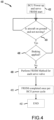
- a method 400 may be used to perform health monitoring of a servo valve 252 from FIG. 2 prior to flight of an aircraft, in accordance with various embodiments.
- the method 400 may start in block 402.
- the brake controller may determine that the brake controller 208 from FIG. 2 has been powered up (e.g., when the aircraft is powered on by a pilot).
- the brake controller may further determine whether the aircraft is on the ground and not moving. For example, the brake controller may make this determination in response to receiving an aircraft speed from a speed sensor or the like and comparing it to a predetermined threshold.
- the predetermined threshold may be less than 10 knots, or the like.
- the method 400 may ensure the aircraft is not about to take off.
- the method 400 may re-check block 404 after a predetermined period of time (e.g., 30 seconds, 1 minute, or the like). Otherwise, the method 400 may proceed to block 406.
- the brake controller may determine if braking is being applied. For example, the brake controller may receive a braking input (e.g., braking input device 214), such as an emergency handle, or a braking pedal.
- a braking input e.g., braking input device 214
- the method 400 may re-check block 404 after a predetermined period of time (e.g., 30 seconds, 1 minute, or the like). Otherwise, the method 400 may proceed to block 408.
- the brake controller may send a frequency response health monitoring (FHRM) command to each servo valve (e.g., the command may be sent in response to the interlock 300 from FIG. 3 being true).
- the FHRM command may initiate a FRHM method (e.g., method 500 as described further herein).
- the brake controller may prevent a frequency response health monitoring of the servo valve from being performed again. For example, a frequency response health monitoring of the servo valves may be performed only once per brake controller power cycle.
- the method 400 may end.
- a method 500 may be performed by a brake controller to perform a frequency response health monitoring of a servo valve after brake controller power up.
- the method 500 may be performed once the interlock function 300 from FIG. 3 is met and/or blocks 404, 406 from FIG. 4 are met.
- the method 500 may begin in block 502 where a brake controller may command a variable current to be supplied to a servo valve.
- a sine wave corresponding to a midpoint pressure e.g., 1500 psi +/- 10%
- the brake controller may calculate an average phase shift over a predetermined period of time (e.g., two seconds, five seconds, or the like). For example, by monitoring the peaks and valleys of the current and pressure signals and the timing in between the peaks and valleys, the brake controller may determine an average delay or phase shift during the predetermined time period (e.g., two seconds, five seconds, or the like.
- a predetermined period of time e.g., two seconds, five seconds, or the like.
- the brake controller may receive an ambient temperature measurement from a temperature sensor of the aircraft.
- the brake controller may assume ambient temperature is accurate because the brake controller is being powered up, so a brake control module with the brake controller would likely be the same temperature as an ambient temperature.
- the brake controller may compare the average phase shift from block 504 to a predetermined phase shift threshold.
- the brake controller may compare the calculated phase shift from block 504 to a table stored in memory that provides the acceptable values of phase shifts for a given temperature. These acceptable values may be determined during the design and validation phases of the brake system.
- a threshold phase shift at 50 Hz and room temperature may comprise 30 degrees.
- a calculated phase shift at 50 Hz that exceeds 30 degrees may indicate the servo valve may need maintenance soon.
- the predetermined phase shift threshold may be adjusted by the brake controller over time to adjust the method 500 more finely.
- the brake controller may count a number of phase shift exceedances over a number of power ups. For example, the brake controller may count the number of phase shift exceedances over a number of power ups in a row and provide an indication that service of a servo valve is need when the phase shift repeatedly exceeds the predetermined phase shift threshold over a predetermined number of brake controller power ups. In response to the phase shift repeatedly exceeding the predetermined phase shift threshold, the brake controller may generate a message that service will be needed soon to an indicator (e.g., indicator 260 from FIG. 2 ).
- an indicator e.g., indicator 260 from FIG. 2 .
- the systems and methods described herein may provide a daily assessment over the life time of a brake control module of frequency response characteristics and potential degradation. In various embodiments, these systems and methods may provide early detection of a servo valve performance degradation and provide a means to perform preventative maintenance in a scheduled manner.
- references to "one embodiment”, “an embodiment”, “an example embodiment”, etc. indicate that the embodiment described may include a particular feature, structure, or characteristic, but every embodiment may not necessarily include the particular feature, structure, or characteristic. Moreover, such phrases are not necessarily referring to the same embodiment. Further, when a particular feature, structure, or characteristic is described in connection with an embodiment, it is submitted that it is within the knowledge of one skilled in the art to affect such feature, structure, or characteristic in connection with other embodiments whether or not explicitly described. After reading the description, it will be apparent to one skilled in the relevant art(s) how to implement the disclosure in alternative embodiments.
Landscapes
- Engineering & Computer Science (AREA)
- Mechanical Engineering (AREA)
- Transportation (AREA)
- Aviation & Aerospace Engineering (AREA)
- Regulating Braking Force (AREA)
- Valves And Accessory Devices For Braking Systems (AREA)
Applications Claiming Priority (2)
| Application Number | Priority Date | Filing Date | Title |
|---|---|---|---|
| US17/109,803 US11565682B2 (en) | 2020-12-02 | 2020-12-02 | Health monitoring systems and methods for servo valves |
| EP21211102.5A EP4008593B1 (fr) | 2020-12-02 | 2021-11-29 | Systèmes et procédés de surveillance de santé pour servovalves |
Related Parent Applications (1)
| Application Number | Title | Priority Date | Filing Date |
|---|---|---|---|
| EP21211102.5A Division EP4008593B1 (fr) | 2020-12-02 | 2021-11-29 | Systèmes et procédés de surveillance de santé pour servovalves |
Publications (3)
| Publication Number | Publication Date |
|---|---|
| EP4375186A2 true EP4375186A2 (fr) | 2024-05-29 |
| EP4375186A3 EP4375186A3 (fr) | 2024-08-07 |
| EP4375186B1 EP4375186B1 (fr) | 2025-11-19 |
Family
ID=78819392
Family Applications (2)
| Application Number | Title | Priority Date | Filing Date |
|---|---|---|---|
| EP21211102.5A Active EP4008593B1 (fr) | 2020-12-02 | 2021-11-29 | Systèmes et procédés de surveillance de santé pour servovalves |
| EP24170296.8A Active EP4375186B1 (fr) | 2020-12-02 | 2021-11-29 | Systèmes et procédés de surveillance de l'état de santé pour servovalves |
Family Applications Before (1)
| Application Number | Title | Priority Date | Filing Date |
|---|---|---|---|
| EP21211102.5A Active EP4008593B1 (fr) | 2020-12-02 | 2021-11-29 | Systèmes et procédés de surveillance de santé pour servovalves |
Country Status (2)
| Country | Link |
|---|---|
| US (1) | US11565682B2 (fr) |
| EP (2) | EP4008593B1 (fr) |
Family Cites Families (6)
| Publication number | Priority date | Publication date | Assignee | Title |
|---|---|---|---|---|
| US7128376B2 (en) | 2003-05-30 | 2006-10-31 | Goodrich Corporation | Redundant architecture for brake-by-wire system |
| FR2981133B1 (fr) | 2011-10-10 | 2013-10-25 | In Lhc | Procede de detection de defaillance d'une servovalve et servovalve faisant application. |
| CN107515105B (zh) | 2016-06-15 | 2021-03-30 | 中国科学院沈阳自动化研究所 | 基于柱塞振动信号的电磁阀故障诊断方法 |
| US10442422B2 (en) * | 2017-12-22 | 2019-10-15 | Goodrich Corporation | Systems and methods for monitoring a health status of a servo valve |
| US10703464B2 (en) | 2018-07-12 | 2020-07-07 | Goodrich Corporation | Architecture for locked wheel and antiskid performance |
| US10933849B2 (en) * | 2018-10-29 | 2021-03-02 | Goodrich Corporation | Systems and methods for rapid convergence antiskid initialization |
-
2020
- 2020-12-02 US US17/109,803 patent/US11565682B2/en active Active
-
2021
- 2021-11-29 EP EP21211102.5A patent/EP4008593B1/fr active Active
- 2021-11-29 EP EP24170296.8A patent/EP4375186B1/fr active Active
Also Published As
| Publication number | Publication date |
|---|---|
| EP4008593A1 (fr) | 2022-06-08 |
| EP4375186B1 (fr) | 2025-11-19 |
| EP4375186A3 (fr) | 2024-08-07 |
| US11565682B2 (en) | 2023-01-31 |
| US20220169229A1 (en) | 2022-06-02 |
| EP4008593B1 (fr) | 2024-05-01 |
Similar Documents
| Publication | Publication Date | Title |
|---|---|---|
| US12179912B2 (en) | Hybrid brake system | |
| EP4541672A2 (fr) | Systèmes et procédés de freinage hybrides | |
| EP3459798B1 (fr) | Système de commande de frein primaire avec une surpassement de système de véhicules alternés | |
| EP3666648B1 (fr) | Réalisation de test de frein en vol en approche | |
| US12486050B2 (en) | Hybrid brake systems and methods | |
| US11970263B2 (en) | Hybrid brake systems and methods for load cell calibration | |
| EP3798121B1 (fr) | Systèmes et procédés d'initialisation de freinage automatique | |
| EP4180287B1 (fr) | Système et procédé de surveillance de l'état des freins | |
| US11492103B2 (en) | Distributed brake control systems and methods for high efficiency antiskid performance | |
| US12049215B2 (en) | Systems and methods to detect shut off valve failure for improved uncommanded braking | |
| FR2953266A1 (fr) | Procede de surveillance d'un dispositif d'irreversibilite d'actionneur de plan horizontal reglable, systeme et aeronef correspondants | |
| EP3909818B1 (fr) | Détection de défaillance de frein à l'aide de la vitesse des roues pendant la rétraction du train d'atterrissage | |
| US20180297565A1 (en) | Electrical power connection in an emergency park brake system | |
| EP4375186B1 (fr) | Systèmes et procédés de surveillance de l'état de santé pour servovalves | |
| US11305745B2 (en) | Shutoff valve control system | |
| US12162456B2 (en) | Feel adjustment braking systems and methods | |
| CN114919737A (zh) | 飞行器及其制动控制系统、起落架和进行制动的方法 |
Legal Events
| Date | Code | Title | Description |
|---|---|---|---|
| PUAI | Public reference made under article 153(3) epc to a published international application that has entered the european phase |
Free format text: ORIGINAL CODE: 0009012 |
|
| STAA | Information on the status of an ep patent application or granted ep patent |
Free format text: STATUS: THE APPLICATION HAS BEEN PUBLISHED |
|
| AC | Divisional application: reference to earlier application |
Ref document number: 4008593 Country of ref document: EP Kind code of ref document: P |
|
| AK | Designated contracting states |
Kind code of ref document: A2 Designated state(s): AL AT BE BG CH CY CZ DE DK EE ES FI FR GB GR HR HU IE IS IT LI LT LU LV MC MK MT NL NO PL PT RO RS SE SI SK SM TR |
|
| REG | Reference to a national code |
Ref country code: DE Ref legal event code: R079 Ipc: B60T0008170000 Ref country code: DE Ref legal event code: R079 Ref document number: 602021042885 Country of ref document: DE Free format text: PREVIOUS MAIN CLASS: B64C0025420000 Ipc: B60T0008170000 |
|
| PUAL | Search report despatched |
Free format text: ORIGINAL CODE: 0009013 |
|
| AK | Designated contracting states |
Kind code of ref document: A3 Designated state(s): AL AT BE BG CH CY CZ DE DK EE ES FI FR GB GR HR HU IE IS IT LI LT LU LV MC MK MT NL NO PL PT RO RS SE SI SK SM TR |
|
| RIC1 | Information provided on ipc code assigned before grant |
Ipc: B60T 8/00 20060101ALI20240704BHEP Ipc: B64C 25/42 20060101ALI20240704BHEP Ipc: B60T 17/22 20060101ALI20240704BHEP Ipc: B60T 8/32 20060101ALI20240704BHEP Ipc: B60T 8/17 20060101AFI20240704BHEP |
|
| STAA | Information on the status of an ep patent application or granted ep patent |
Free format text: STATUS: REQUEST FOR EXAMINATION WAS MADE |
|
| 17P | Request for examination filed |
Effective date: 20250206 |
|
| RIC1 | Information provided on ipc code assigned before grant |
Ipc: B60T 8/00 20060101ALI20250507BHEP Ipc: B64C 25/42 20060101ALI20250507BHEP Ipc: B60T 17/22 20060101ALI20250507BHEP Ipc: B60T 8/32 20060101ALI20250507BHEP Ipc: B60T 8/17 20060101AFI20250507BHEP |
|
| GRAP | Despatch of communication of intention to grant a patent |
Free format text: ORIGINAL CODE: EPIDOSNIGR1 |
|
| STAA | Information on the status of an ep patent application or granted ep patent |
Free format text: STATUS: GRANT OF PATENT IS INTENDED |
|
| INTG | Intention to grant announced |
Effective date: 20250623 |
|
| GRAS | Grant fee paid |
Free format text: ORIGINAL CODE: EPIDOSNIGR3 |
|
| GRAA | (expected) grant |
Free format text: ORIGINAL CODE: 0009210 |
|
| STAA | Information on the status of an ep patent application or granted ep patent |
Free format text: STATUS: THE PATENT HAS BEEN GRANTED |
|
| AC | Divisional application: reference to earlier application |
Ref document number: 4008593 Country of ref document: EP Kind code of ref document: P |
|
| AK | Designated contracting states |
Kind code of ref document: B1 Designated state(s): AL AT BE BG CH CY CZ DE DK EE ES FI FR GB GR HR HU IE IS IT LI LT LU LV MC MK MT NL NO PL PT RO RS SE SI SK SM TR |
|
| REG | Reference to a national code |
Ref country code: CH Ref legal event code: F10 Free format text: ST27 STATUS EVENT CODE: U-0-0-F10-F00 (AS PROVIDED BY THE NATIONAL OFFICE) Effective date: 20251119 Ref country code: GB Ref legal event code: FG4D |
|
| REG | Reference to a national code |
Ref country code: DE Ref legal event code: R096 Ref document number: 602021042885 Country of ref document: DE |
|
| REG | Reference to a national code |
Ref country code: IE Ref legal event code: FG4D |
|
| PGFP | Annual fee paid to national office [announced via postgrant information from national office to epo] |
Ref country code: GB Payment date: 20251220 Year of fee payment: 5 |
|
| PGFP | Annual fee paid to national office [announced via postgrant information from national office to epo] |
Ref country code: AT Payment date: 20260113 Year of fee payment: 5 |
|
| PGFP | Annual fee paid to national office [announced via postgrant information from national office to epo] |
Ref country code: FR Payment date: 20251217 Year of fee payment: 5 |