EP4375509A1 - Circuit de réfrigérant et compresseur de réfrigérant - Google Patents
Circuit de réfrigérant et compresseur de réfrigérant Download PDFInfo
- Publication number
- EP4375509A1 EP4375509A1 EP23211431.4A EP23211431A EP4375509A1 EP 4375509 A1 EP4375509 A1 EP 4375509A1 EP 23211431 A EP23211431 A EP 23211431A EP 4375509 A1 EP4375509 A1 EP 4375509A1
- Authority
- EP
- European Patent Office
- Prior art keywords
- base module
- module
- unit
- control unit
- base
- Prior art date
- Legal status (The legal status is an assumption and is not a legal conclusion. Google has not performed a legal analysis and makes no representation as to the accuracy of the status listed.)
- Granted
Links
Images


Classifications
-
- F—MECHANICAL ENGINEERING; LIGHTING; HEATING; WEAPONS; BLASTING
- F04—POSITIVE - DISPLACEMENT MACHINES FOR LIQUIDS; PUMPS FOR LIQUIDS OR ELASTIC FLUIDS
- F04B—POSITIVE-DISPLACEMENT MACHINES FOR LIQUIDS; PUMPS
- F04B39/00—Component parts, details, or accessories, of pumps or pumping systems specially adapted for elastic fluids, not otherwise provided for in, or of interest apart from, groups F04B25/00 - F04B37/00
- F04B39/12—Casings; Cylinders; Cylinder heads; Fluid connections
- F04B39/121—Casings
-
- F—MECHANICAL ENGINEERING; LIGHTING; HEATING; WEAPONS; BLASTING
- F25—REFRIGERATION OR COOLING; COMBINED HEATING AND REFRIGERATION SYSTEMS; HEAT PUMP SYSTEMS; MANUFACTURE OR STORAGE OF ICE; LIQUEFACTION SOLIDIFICATION OF GASES
- F25B—REFRIGERATION MACHINES, PLANTS OR SYSTEMS; COMBINED HEATING AND REFRIGERATION SYSTEMS; HEAT PUMP SYSTEMS
- F25B49/00—Arrangement or mounting of control or safety devices
- F25B49/02—Arrangement or mounting of control or safety devices for compression type machines, plants or systems
- F25B49/022—Compressor control arrangements
-
- F—MECHANICAL ENGINEERING; LIGHTING; HEATING; WEAPONS; BLASTING
- F04—POSITIVE - DISPLACEMENT MACHINES FOR LIQUIDS; PUMPS FOR LIQUIDS OR ELASTIC FLUIDS
- F04B—POSITIVE-DISPLACEMENT MACHINES FOR LIQUIDS; PUMPS
- F04B49/00—Control, e.g. of pump delivery, or pump pressure of, or safety measures for, machines, pumps, or pumping installations, not otherwise provided for, or of interest apart from, groups F04B1/00 - F04B47/00
- F04B49/06—Control using electricity
- F04B49/065—Control using electricity and making use of computers
-
- F—MECHANICAL ENGINEERING; LIGHTING; HEATING; WEAPONS; BLASTING
- F04—POSITIVE - DISPLACEMENT MACHINES FOR LIQUIDS; PUMPS FOR LIQUIDS OR ELASTIC FLUIDS
- F04B—POSITIVE-DISPLACEMENT MACHINES FOR LIQUIDS; PUMPS
- F04B35/00—Piston pumps specially adapted for elastic fluids and characterised by the driving means to their working members, or by combination with, or adaptation to, specific driving engines or motors, not otherwise provided for
- F04B35/04—Piston pumps specially adapted for elastic fluids and characterised by the driving means to their working members, or by combination with, or adaptation to, specific driving engines or motors, not otherwise provided for the means being electric
-
- F—MECHANICAL ENGINEERING; LIGHTING; HEATING; WEAPONS; BLASTING
- F04—POSITIVE - DISPLACEMENT MACHINES FOR LIQUIDS; PUMPS FOR LIQUIDS OR ELASTIC FLUIDS
- F04B—POSITIVE-DISPLACEMENT MACHINES FOR LIQUIDS; PUMPS
- F04B39/00—Component parts, details, or accessories, of pumps or pumping systems specially adapted for elastic fluids, not otherwise provided for in, or of interest apart from, groups F04B25/00 - F04B37/00
- F04B39/02—Lubrication
- F04B39/0207—Lubrication with lubrication control systems
-
- F—MECHANICAL ENGINEERING; LIGHTING; HEATING; WEAPONS; BLASTING
- F04—POSITIVE - DISPLACEMENT MACHINES FOR LIQUIDS; PUMPS FOR LIQUIDS OR ELASTIC FLUIDS
- F04B—POSITIVE-DISPLACEMENT MACHINES FOR LIQUIDS; PUMPS
- F04B41/00—Pumping installations or systems specially adapted for elastic fluids
- F04B41/06—Combinations of two or more pumps
-
- F—MECHANICAL ENGINEERING; LIGHTING; HEATING; WEAPONS; BLASTING
- F04—POSITIVE - DISPLACEMENT MACHINES FOR LIQUIDS; PUMPS FOR LIQUIDS OR ELASTIC FLUIDS
- F04B—POSITIVE-DISPLACEMENT MACHINES FOR LIQUIDS; PUMPS
- F04B51/00—Testing machines, pumps, or pumping installations
-
- F—MECHANICAL ENGINEERING; LIGHTING; HEATING; WEAPONS; BLASTING
- F04—POSITIVE - DISPLACEMENT MACHINES FOR LIQUIDS; PUMPS FOR LIQUIDS OR ELASTIC FLUIDS
- F04C—ROTARY-PISTON, OR OSCILLATING-PISTON, POSITIVE-DISPLACEMENT MACHINES FOR LIQUIDS; ROTARY-PISTON, OR OSCILLATING-PISTON, POSITIVE-DISPLACEMENT PUMPS
- F04C28/00—Control of, monitoring of, or safety arrangements for, pumps or pumping installations specially adapted for elastic fluids
- F04C28/28—Safety arrangements; Monitoring
-
- F—MECHANICAL ENGINEERING; LIGHTING; HEATING; WEAPONS; BLASTING
- F04—POSITIVE - DISPLACEMENT MACHINES FOR LIQUIDS; PUMPS FOR LIQUIDS OR ELASTIC FLUIDS
- F04C—ROTARY-PISTON, OR OSCILLATING-PISTON, POSITIVE-DISPLACEMENT MACHINES FOR LIQUIDS; ROTARY-PISTON, OR OSCILLATING-PISTON, POSITIVE-DISPLACEMENT PUMPS
- F04C29/00—Component parts, details or accessories of pumps or pumping installations, not provided for in groups F04C18/00 - F04C28/00
- F04C29/04—Heating; Cooling; Heat insulation
-
- F—MECHANICAL ENGINEERING; LIGHTING; HEATING; WEAPONS; BLASTING
- F25—REFRIGERATION OR COOLING; COMBINED HEATING AND REFRIGERATION SYSTEMS; HEAT PUMP SYSTEMS; MANUFACTURE OR STORAGE OF ICE; LIQUEFACTION SOLIDIFICATION OF GASES
- F25B—REFRIGERATION MACHINES, PLANTS OR SYSTEMS; COMBINED HEATING AND REFRIGERATION SYSTEMS; HEAT PUMP SYSTEMS
- F25B1/00—Compression machines, plants or systems with non-reversible cycle
- F25B1/005—Compression machines, plants or systems with non-reversible cycle of the single unit type
-
- F—MECHANICAL ENGINEERING; LIGHTING; HEATING; WEAPONS; BLASTING
- F25—REFRIGERATION OR COOLING; COMBINED HEATING AND REFRIGERATION SYSTEMS; HEAT PUMP SYSTEMS; MANUFACTURE OR STORAGE OF ICE; LIQUEFACTION SOLIDIFICATION OF GASES
- F25B—REFRIGERATION MACHINES, PLANTS OR SYSTEMS; COMBINED HEATING AND REFRIGERATION SYSTEMS; HEAT PUMP SYSTEMS
- F25B31/00—Compressor arrangements
- F25B31/002—Lubrication
-
- F—MECHANICAL ENGINEERING; LIGHTING; HEATING; WEAPONS; BLASTING
- F25—REFRIGERATION OR COOLING; COMBINED HEATING AND REFRIGERATION SYSTEMS; HEAT PUMP SYSTEMS; MANUFACTURE OR STORAGE OF ICE; LIQUEFACTION SOLIDIFICATION OF GASES
- F25B—REFRIGERATION MACHINES, PLANTS OR SYSTEMS; COMBINED HEATING AND REFRIGERATION SYSTEMS; HEAT PUMP SYSTEMS
- F25B49/00—Arrangement or mounting of control or safety devices
- F25B49/02—Arrangement or mounting of control or safety devices for compression type machines, plants or systems
-
- F—MECHANICAL ENGINEERING; LIGHTING; HEATING; WEAPONS; BLASTING
- F04—POSITIVE - DISPLACEMENT MACHINES FOR LIQUIDS; PUMPS FOR LIQUIDS OR ELASTIC FLUIDS
- F04B—POSITIVE-DISPLACEMENT MACHINES FOR LIQUIDS; PUMPS
- F04B2205/00—Fluid parameters
- F04B2205/10—Inlet temperature
-
- F—MECHANICAL ENGINEERING; LIGHTING; HEATING; WEAPONS; BLASTING
- F04—POSITIVE - DISPLACEMENT MACHINES FOR LIQUIDS; PUMPS FOR LIQUIDS OR ELASTIC FLUIDS
- F04B—POSITIVE-DISPLACEMENT MACHINES FOR LIQUIDS; PUMPS
- F04B2205/00—Fluid parameters
- F04B2205/11—Outlet temperature
-
- F—MECHANICAL ENGINEERING; LIGHTING; HEATING; WEAPONS; BLASTING
- F04—POSITIVE - DISPLACEMENT MACHINES FOR LIQUIDS; PUMPS FOR LIQUIDS OR ELASTIC FLUIDS
- F04B—POSITIVE-DISPLACEMENT MACHINES FOR LIQUIDS; PUMPS
- F04B2205/00—Fluid parameters
- F04B2205/17—Opening width of a throttling device
- F04B2205/171—Opening width of a throttling device before the pump inlet
-
- F—MECHANICAL ENGINEERING; LIGHTING; HEATING; WEAPONS; BLASTING
- F04—POSITIVE - DISPLACEMENT MACHINES FOR LIQUIDS; PUMPS FOR LIQUIDS OR ELASTIC FLUIDS
- F04B—POSITIVE-DISPLACEMENT MACHINES FOR LIQUIDS; PUMPS
- F04B2207/00—External parameters
- F04B2207/03—External temperature
-
- F—MECHANICAL ENGINEERING; LIGHTING; HEATING; WEAPONS; BLASTING
- F04—POSITIVE - DISPLACEMENT MACHINES FOR LIQUIDS; PUMPS FOR LIQUIDS OR ELASTIC FLUIDS
- F04B—POSITIVE-DISPLACEMENT MACHINES FOR LIQUIDS; PUMPS
- F04B2207/00—External parameters
- F04B2207/70—Warnings
-
- F—MECHANICAL ENGINEERING; LIGHTING; HEATING; WEAPONS; BLASTING
- F04—POSITIVE - DISPLACEMENT MACHINES FOR LIQUIDS; PUMPS FOR LIQUIDS OR ELASTIC FLUIDS
- F04B—POSITIVE-DISPLACEMENT MACHINES FOR LIQUIDS; PUMPS
- F04B39/00—Component parts, details, or accessories, of pumps or pumping systems specially adapted for elastic fluids, not otherwise provided for in, or of interest apart from, groups F04B25/00 - F04B37/00
- F04B39/06—Cooling; Heating; Prevention of freezing
- F04B39/062—Cooling by injecting a liquid in the gas to be compressed
-
- F—MECHANICAL ENGINEERING; LIGHTING; HEATING; WEAPONS; BLASTING
- F04—POSITIVE - DISPLACEMENT MACHINES FOR LIQUIDS; PUMPS FOR LIQUIDS OR ELASTIC FLUIDS
- F04B—POSITIVE-DISPLACEMENT MACHINES FOR LIQUIDS; PUMPS
- F04B39/00—Component parts, details, or accessories, of pumps or pumping systems specially adapted for elastic fluids, not otherwise provided for in, or of interest apart from, groups F04B25/00 - F04B37/00
- F04B39/06—Cooling; Heating; Prevention of freezing
- F04B39/066—Cooling by ventilation
-
- F—MECHANICAL ENGINEERING; LIGHTING; HEATING; WEAPONS; BLASTING
- F04—POSITIVE - DISPLACEMENT MACHINES FOR LIQUIDS; PUMPS FOR LIQUIDS OR ELASTIC FLUIDS
- F04B—POSITIVE-DISPLACEMENT MACHINES FOR LIQUIDS; PUMPS
- F04B49/00—Control, e.g. of pump delivery, or pump pressure of, or safety measures for, machines, pumps, or pumping installations, not otherwise provided for, or of interest apart from, groups F04B1/00 - F04B47/00
- F04B49/02—Stopping, starting, unloading or idling control
- F04B49/03—Stopping, starting, unloading or idling control by means of valves
-
- F—MECHANICAL ENGINEERING; LIGHTING; HEATING; WEAPONS; BLASTING
- F04—POSITIVE - DISPLACEMENT MACHINES FOR LIQUIDS; PUMPS FOR LIQUIDS OR ELASTIC FLUIDS
- F04B—POSITIVE-DISPLACEMENT MACHINES FOR LIQUIDS; PUMPS
- F04B49/00—Control, e.g. of pump delivery, or pump pressure of, or safety measures for, machines, pumps, or pumping installations, not otherwise provided for, or of interest apart from, groups F04B1/00 - F04B47/00
- F04B49/10—Other safety measures
-
- F—MECHANICAL ENGINEERING; LIGHTING; HEATING; WEAPONS; BLASTING
- F04—POSITIVE - DISPLACEMENT MACHINES FOR LIQUIDS; PUMPS FOR LIQUIDS OR ELASTIC FLUIDS
- F04C—ROTARY-PISTON, OR OSCILLATING-PISTON, POSITIVE-DISPLACEMENT MACHINES FOR LIQUIDS; ROTARY-PISTON, OR OSCILLATING-PISTON, POSITIVE-DISPLACEMENT PUMPS
- F04C18/00—Rotary-piston pumps specially adapted for elastic fluids
- F04C18/02—Rotary-piston pumps specially adapted for elastic fluids of arcuate-engagement type, i.e. with circular translatory movement of co-operating members, each member having the same number of teeth or tooth-equivalents
- F04C18/0207—Rotary-piston pumps specially adapted for elastic fluids of arcuate-engagement type, i.e. with circular translatory movement of co-operating members, each member having the same number of teeth or tooth-equivalents both members having co-operating elements in spiral form
-
- F—MECHANICAL ENGINEERING; LIGHTING; HEATING; WEAPONS; BLASTING
- F04—POSITIVE - DISPLACEMENT MACHINES FOR LIQUIDS; PUMPS FOR LIQUIDS OR ELASTIC FLUIDS
- F04C—ROTARY-PISTON, OR OSCILLATING-PISTON, POSITIVE-DISPLACEMENT MACHINES FOR LIQUIDS; ROTARY-PISTON, OR OSCILLATING-PISTON, POSITIVE-DISPLACEMENT PUMPS
- F04C18/00—Rotary-piston pumps specially adapted for elastic fluids
- F04C18/08—Rotary-piston pumps specially adapted for elastic fluids of intermeshing-engagement type, i.e. with engagement of co-operating members similar to that of toothed gearing
- F04C18/12—Rotary-piston pumps specially adapted for elastic fluids of intermeshing-engagement type, i.e. with engagement of co-operating members similar to that of toothed gearing of other than internal-axis type
- F04C18/14—Rotary-piston pumps specially adapted for elastic fluids of intermeshing-engagement type, i.e. with engagement of co-operating members similar to that of toothed gearing of other than internal-axis type with toothed rotary pistons
- F04C18/16—Rotary-piston pumps specially adapted for elastic fluids of intermeshing-engagement type, i.e. with engagement of co-operating members similar to that of toothed gearing of other than internal-axis type with toothed rotary pistons with helical teeth, e.g. chevron-shaped, screw type
-
- F—MECHANICAL ENGINEERING; LIGHTING; HEATING; WEAPONS; BLASTING
- F04—POSITIVE - DISPLACEMENT MACHINES FOR LIQUIDS; PUMPS FOR LIQUIDS OR ELASTIC FLUIDS
- F04C—ROTARY-PISTON, OR OSCILLATING-PISTON, POSITIVE-DISPLACEMENT MACHINES FOR LIQUIDS; ROTARY-PISTON, OR OSCILLATING-PISTON, POSITIVE-DISPLACEMENT PUMPS
- F04C2210/00—Fluid
- F04C2210/26—Refrigerants with particular properties, e.g. HFC-134a
-
- F—MECHANICAL ENGINEERING; LIGHTING; HEATING; WEAPONS; BLASTING
- F04—POSITIVE - DISPLACEMENT MACHINES FOR LIQUIDS; PUMPS FOR LIQUIDS OR ELASTIC FLUIDS
- F04C—ROTARY-PISTON, OR OSCILLATING-PISTON, POSITIVE-DISPLACEMENT MACHINES FOR LIQUIDS; ROTARY-PISTON, OR OSCILLATING-PISTON, POSITIVE-DISPLACEMENT PUMPS
- F04C2240/00—Components
- F04C2240/30—Casings or housings
-
- F—MECHANICAL ENGINEERING; LIGHTING; HEATING; WEAPONS; BLASTING
- F04—POSITIVE - DISPLACEMENT MACHINES FOR LIQUIDS; PUMPS FOR LIQUIDS OR ELASTIC FLUIDS
- F04C—ROTARY-PISTON, OR OSCILLATING-PISTON, POSITIVE-DISPLACEMENT MACHINES FOR LIQUIDS; ROTARY-PISTON, OR OSCILLATING-PISTON, POSITIVE-DISPLACEMENT PUMPS
- F04C28/00—Control of, monitoring of, or safety arrangements for, pumps or pumping installations specially adapted for elastic fluids
- F04C28/10—Control of, monitoring of, or safety arrangements for, pumps or pumping installations specially adapted for elastic fluids characterised by changing the positions of the inlet or outlet openings with respect to the working chamber
- F04C28/12—Control of, monitoring of, or safety arrangements for, pumps or pumping installations specially adapted for elastic fluids characterised by changing the positions of the inlet or outlet openings with respect to the working chamber using sliding valves
-
- F—MECHANICAL ENGINEERING; LIGHTING; HEATING; WEAPONS; BLASTING
- F04—POSITIVE - DISPLACEMENT MACHINES FOR LIQUIDS; PUMPS FOR LIQUIDS OR ELASTIC FLUIDS
- F04C—ROTARY-PISTON, OR OSCILLATING-PISTON, POSITIVE-DISPLACEMENT MACHINES FOR LIQUIDS; ROTARY-PISTON, OR OSCILLATING-PISTON, POSITIVE-DISPLACEMENT PUMPS
- F04C28/00—Control of, monitoring of, or safety arrangements for, pumps or pumping installations specially adapted for elastic fluids
- F04C28/24—Control of, monitoring of, or safety arrangements for, pumps or pumping installations specially adapted for elastic fluids characterised by using valves controlling pressure or flow rate, e.g. discharge valves or unloading valves
- F04C28/26—Control of, monitoring of, or safety arrangements for, pumps or pumping installations specially adapted for elastic fluids characterised by using valves controlling pressure or flow rate, e.g. discharge valves or unloading valves using bypass channels
-
- F—MECHANICAL ENGINEERING; LIGHTING; HEATING; WEAPONS; BLASTING
- F25—REFRIGERATION OR COOLING; COMBINED HEATING AND REFRIGERATION SYSTEMS; HEAT PUMP SYSTEMS; MANUFACTURE OR STORAGE OF ICE; LIQUEFACTION SOLIDIFICATION OF GASES
- F25B—REFRIGERATION MACHINES, PLANTS OR SYSTEMS; COMBINED HEATING AND REFRIGERATION SYSTEMS; HEAT PUMP SYSTEMS
- F25B2500/00—Problems to be solved
- F25B2500/13—Vibrations
-
- F—MECHANICAL ENGINEERING; LIGHTING; HEATING; WEAPONS; BLASTING
- F25—REFRIGERATION OR COOLING; COMBINED HEATING AND REFRIGERATION SYSTEMS; HEAT PUMP SYSTEMS; MANUFACTURE OR STORAGE OF ICE; LIQUEFACTION SOLIDIFICATION OF GASES
- F25B—REFRIGERATION MACHINES, PLANTS OR SYSTEMS; COMBINED HEATING AND REFRIGERATION SYSTEMS; HEAT PUMP SYSTEMS
- F25B2500/00—Problems to be solved
- F25B2500/16—Lubrication
-
- F—MECHANICAL ENGINEERING; LIGHTING; HEATING; WEAPONS; BLASTING
- F25—REFRIGERATION OR COOLING; COMBINED HEATING AND REFRIGERATION SYSTEMS; HEAT PUMP SYSTEMS; MANUFACTURE OR STORAGE OF ICE; LIQUEFACTION SOLIDIFICATION OF GASES
- F25B—REFRIGERATION MACHINES, PLANTS OR SYSTEMS; COMBINED HEATING AND REFRIGERATION SYSTEMS; HEAT PUMP SYSTEMS
- F25B2700/00—Sensing or detecting of parameters; Sensors therefor
- F25B2700/03—Oil level
-
- F—MECHANICAL ENGINEERING; LIGHTING; HEATING; WEAPONS; BLASTING
- F25—REFRIGERATION OR COOLING; COMBINED HEATING AND REFRIGERATION SYSTEMS; HEAT PUMP SYSTEMS; MANUFACTURE OR STORAGE OF ICE; LIQUEFACTION SOLIDIFICATION OF GASES
- F25B—REFRIGERATION MACHINES, PLANTS OR SYSTEMS; COMBINED HEATING AND REFRIGERATION SYSTEMS; HEAT PUMP SYSTEMS
- F25B2700/00—Sensing or detecting of parameters; Sensors therefor
- F25B2700/19—Pressures
- F25B2700/193—Pressures of the compressor
- F25B2700/1932—Oil pressures
Definitions
- the invention relates to a refrigerant compressor which has a compressor unit which sucks in refrigerant with a suction connection, compresses it and discharges it via a pressure connection, wherein the refrigerant compressor has an electric drive unit which drives the compressor unit and wherein the refrigerant compressor is provided with a control unit which interacts with operating units and/or condition detection units assigned to the refrigerant compressor or the refrigerant circuit.
- the invention is based on the object of creating a control unit which can interact with a wide variety of operating units and/or condition detection units.
- control unit comprises a base module which has at least one processor and at least one memory for the necessary program code for operating the processor as well as connections for operating units executing basic functions and/or status detection units, and that the processor and the program code stored in the memory are designed such that operating units executing additional functions and/or status detection units can also be operated with them via an additional module that can be connected to the base module.
- the advantage of the solution according to the invention is that the base module not only offers the possibility of executing the operating units and status detection units that can be connected to it for the basic functions, but is already designed in such a way that it also offers the possibility of executing additional functions of an additional module that can be connected to the base module, so that the functionalities provided in the base module also provide for the operation of the additional functions and thus all basic functions and additional functions that may be provided can be executed by the at least one processor and the at least one memory of the base module.
- the basic module and the functionalities provided in it also prevent communication problems between the basic module and the additional modules intended for connection to it, especially since a wide variety of additional modules can be combined with the basic module.
- a particularly advantageous solution of the invention provides that the base module for the execution of additional functions can be connected to an additional module which has connections for operating units and/or status detection units executing the additional functions, and that the additional module enables the execution of the additional functions by operating the operating units and/or status detection units by means of the base module through mediated communication between the base module and the operating units and/or status detection units connected to the additional module.
- all programs and data required for the basic functions and additional functions are therefore available in the basic module, and all operating states are also determined, recorded and stored in the basic module.
- the electrical connection elements are designed as plug-in connection elements, which allow a direct connection between the base module and the additional module.
- the mediating communication of the respective additional module comprises a signal conversion and/or a signal processing and/or an intelligent signal processing and/or an evaluating signal processing.
- the mediating communication by the respective additional module includes not only the forwarding of control information from the base module for the operation of the operating units and status detection units, but also an adaptation of the control information of the processor to the requirements of the respective operating units and status detection units, which can be carried out in particular by output stages of the respective additional module, whereby such output stages can also be designed, for example, as switching units or continuously controllable output stages.
- the mediating communication also includes, for example, a conversion of signals from the status detection units into predetermined data structures for detection by the at least one processor and the at least one memory in the base module.
- standardized communication channels such as a BUS connection
- a particularly advantageous solution provides that different additional modules can be connected to the basic module, each of which enables operation of different combinations of operating units and/or condition detection units through mediating communication between the basic module and these different combinations of operating units or condition monitoring units and thus also adaptation to different applications.
- control unit has a control housing arranged on the refrigerant compressor, which is designed to accommodate the base module and is also designed to accommodate at least one additional module.
- a control housing arranged on the refrigerant compressor is in particular a control housing which is firmly connected to the refrigerant compressor and in particular sits on a component of the refrigerant compressor itself, that is to say on an overall housing and/or on a motor power supply unit of the refrigerant compressor.
- control housing is designed in such a way that different additional modules can be used in addition to the basic module.
- control housing has mounting receptacles for firmly connecting the base module to it.
- control housing has mounting receptacles for firmly connecting the additional module to it.
- the mounting receptacles are arranged on a housing base of the control housing.
- the mounting brackets are connected to the housing base by means of stiffeners.
- Such stiffeners serve in particular to dampen vibrations of the housing base and thus prevent them from being transferred to the base module and, if applicable, the additional module.
- the housing base is provided with vibration-damping structures, in particular in addition to the stiffeners.
- the respective mounting base for the base module and the additional module are arranged on the stiffeners of the housing base, so that these stiffeners provide a stable arrangement of the connection between the base module and the additional module.
- the base module mounted in the control housing and the additional module connected to it are connected to one another by a plug connection.
- the base module for the operating units and/or condition detection units has at least one low-voltage connection, for example for condition detection units, and at least one mains voltage connection, for example for operating units.
- the additional module for operating the operating units and/or condition detection units has at least one low-voltage connection, for example for condition detection units, and at least one mains voltage connection, for example for operating units.
- At least some of the mains voltage connections can be controlled by output stages communicating with the base module.
- At least one of the low-voltage connections can be controlled by the base module.
- the base module has at least one BUS connection unit for a BUS system, wherein the BUS system is preferably a field BUS system for communication with at least one additional module or another base module of another refrigerant compressor unit and/or with configuration and/or reading devices and/or display units.
- the BUS system is preferably a field BUS system for communication with at least one additional module or another base module of another refrigerant compressor unit and/or with configuration and/or reading devices and/or display units.
- the base module has a communication unit for wireless communication, for example via Bluetooth or WiFi, with the system control and/or configuration devices or reading devices and/or display units and/or for communication with additional modules and/or other base modules.
- the base module has a connection for communication with a system controller of the refrigerant circuit in order to receive control signals from the system controller for controlling the refrigerant circuit.
- connection for communication with the system control is the BUS connection unit.
- an advantageous solution provides that the additional module has a BUS connection unit.
- an alternative or additional solution provides that the additional module has a communication unit for wireless communication.
- a further advantageous solution provides that the drive unit can be operated by means of a frequency converter and that the frequency converter is controlled by the base module, whereby the control can be carried out via one of the connections of the base module or via the BUS connection unit or by wireless communication.
- a further advantageous solution provides that the drive unit can be operated by means of a frequency converter and that the frequency converter is controlled by the base module via the additional module, whereby the control via the additional module can be carried out by means of the connections of the additional module or via its BUS connection unit or by wireless communication.
- An advantageous solution provides that the base module and/or the additional module of the control unit is connected to a lubricant sensor as a condition detection unit and that the base module records the values of the lubricant sensor.
- the base module evaluates the values of the lubricant sensor.
- Such an evaluation is carried out in particular by the at least one processor by means of the program code stored in the at least one memory of the base module, wherein in the simplest case reference values are stored and compared with the values of the lubricant sensor.
- the lubricant sensor is an optical lubricant level sensor.
- the lubricant sensor is a float sensor.
- the lubricant sensor is a lubricant differential pressure sensor.
- a further advantageous possibility for realizing an operating unit is that the base module as an operating unit controls a lubricant supply from a lubricant separator to the compressor unit through a lubricant supply unit connected to the base module and/or the additional module.
- the lubricant supply unit can, for example, be designed as a pump.
- a particularly simple solution provides that the lubricant supply unit is designed as a lubricant injection valve.
- a further advantageous solution provides that the base module and/or the additional module of the control unit is connected to a compressed gas temperature sensor as a condition detection unit and that the base module detects the values of the compressed gas temperature sensor.
- the base module evaluates the values of the compressed gas temperature sensor, in particular taking into account reference values stored in the at least one memory.
- a further advantageous solution provides that the base module and/or the additional module of the control unit is connected to a high-pressure sensor as a condition detection unit and that the base module detects the values of the high-pressure sensor.
- the base module can also evaluate the values of the high-pressure sensor by means of the at least one processor and the at least one memory with the program code.
- the base module forwards the values of the high-pressure sensor.
- the refrigerant compressor can also be switched off if the pressure detected by the high-pressure sensor is too high.
- a further advantageous embodiment of the solution according to the invention provides that the base module and/or the additional module of the control unit is connected to a lubricant heater as an operating unit and that in particular the base module switches the lubricant heater on or off, in particular depending on detected operating states of individual units, such as an operating state of the drive unit.
- a further advantageous solution provides that the base module and/or the additional module of the control unit are connected to a power control unit of the compressor unit and that the base module controls the power control unit.
- the base module controls the power control unit according to a power requirement of the system control unit.
- the base module may control the power control unit by means of the at least one processor as a function of the compressed gas temperature detected by the compressed gas temperature sensor, taking into account specifications stored in the memory.
- the base module and/or the additional module of the control unit is connected to a suction gas temperature sensor as a state detection unit and that the base module detects the values of the suction gas temperature sensor.
- the processor of the base module compares the values of the suction gas temperature sensor with reference values stored in the memory or determined by the processor according to an operating state of the refrigerant compressor.
- the base module may communicate with the system control when the suction gas temperature falls below a reference value and at least report to the system control that the suction gas temperature is too low.
- the base module controls the power control unit by means of the at least one processor, taking into account the discharge gas temperature and the suction gas temperature as well as taking into account specifications stored in the memory.
- the power control unit mentioned above is understood to mean, for example, a frequency converter of the electric drive unit.
- the power control unit mentioned above also includes a mechanical power control.
- a reciprocating piston compressor has one or more valves, such as switching valves, which allow individual cylinders or cylinder banks to be activated or deactivated and thus control the performance or achieve start-up relief.
- valves such as switching valves
- valves are used to position an existing power slide or as bypass valves.
- a valve interrupts the refrigerant supply by opening a bypass or by partially lifting the spiral bodies.
- a further advantageous embodiment provides that the base module and/or the additional module of the control unit are connected to a fan for cooling the compressor unit as an operating unit and that the base module controls the fan.
- Such a fan is, for example, a fan for cooling one or more cylinder heads of a reciprocating compressor.
- the base module to control the fan by means of the at least one processor, taking into account the pressure gas temperature and specifications stored in the memory, in particular in order not to exceed a maximum temperature of the compressor unit in the area of its cylinder heads.
- a further advantageous embodiment of the refrigerant compressor provides that the base module and/or the additional module of the control unit is connected to an injection unit for refrigerant as an operating unit and that the base module controls the injection unit.
- Such an injection unit is in particular arranged in such a way that it injects liquid refrigerant for cooling into the refrigerant sucked in by the compressor unit before it is compressed in order to reduce the temperature of the compressor unit when the refrigerant is compressed.
- the refrigerant compressor is a screw compressor, it is alternatively possible to inject refrigerant into a chamber closed by at least one screw.
- the base module controls the injection unit by means of the at least one processor, taking into account the pressure gas temperature and taking into account specifications stored in the memory or determined by the processor in accordance with other state variables, so that an increase in the pressure gas temperature can be avoided by such an injection of liquid coolant.
- a further advantageous solution provides that the base module and/or the additional module of the control unit is connected to an ambient temperature sensor as a condition detection unit and that the base module detects the values of the ambient temperature sensor.
- the base module uses the processor to evaluate the values of the ambient temperature sensor in accordance with reference values specified in the memory.
- the base module controls a blower unit of the high-pressure side heat exchanger of the refrigerant circuit by means of the processor in accordance with the values of a condensation pressure sensor and/or the ambient temperature sensor based on specifications stored in the memory or determined by the processor in accordance with other operating state variables.
- the base module temporarily or permanently takes over the function of the system control for controlling the refrigerant circuit.
- the base module and/or the additional module of the control unit is connected to a cooling point temperature sensor as a condition detection unit and that the base module detects the values of the cooling point temperature sensor.
- the base module may use the processor to compare the cooling point temperature with reference values specified in the memory or determined by the processor on the basis of other operating state variables.
- the base module uses the processor to control a mass flow control unit in the refrigerant circuit, taking into account the cooling point temperature and a control program stored in the memory.
- the base module can at least temporarily or permanently take over the function of the system control and control the refrigerant circuit accordingly.
- a further advantageous solution provides that the base module is designed to carry out a lubricant return operation, controlled by the processor according to a lubricant return program, and that the base module and/or the additional module of the control unit is connected to a switchable output for activating the lubricant return operation as an operating unit, for example by the system control, and that the base module controls the output.
- a further advantageous solution provides that when operating conditions that are likely to cause damage occur, the base module detects these by means of the processor and stores an alarm signal and/or that the base module and/or the additional module of the control unit is connected to a display unit as an operating unit and that the base module controls the display unit in such a way that it displays an alarm signal recognized by the base module.
- At least one lubricant sensor, and/or a compressed gas temperature sensor, and/or possibly a high pressure sensor and/or a lubricant heater are connected to the base module.
- the invention relates to a refrigerant circuit comprising at least one refrigerant compressor, a high-pressure line leading away from the at least one refrigerant compressor, a high-pressure side heat exchanger arranged in the high-pressure line, at least one expansion element following the high-pressure side heat exchanger in the high-pressure line, a low-pressure side heat exchanger following the expansion element and arranged in a low-pressure line, from which the low-pressure line leads to the at least one refrigerant compressor.
- the at least one refrigerant compressor is designed according to one or more of the preceding features.
- the advantage of the solution according to the invention is therefore that the at least one refrigerant compressor in the refrigerant circuit according to the invention can be controlled in a simple manner using a wide variety of operating units and/or condition detection units and can be adapted to these in a simple manner.
- a particularly advantageous solution provides that the refrigerant circuit detects a high-pressure sensor arranged in a high-pressure line, the value of which can advantageously be detected by the control unit of the refrigerant compressor.
- the refrigerant circuit comprises a lubricant separator arranged in the high-pressure line, which thus makes it possible to separate lubricant in a simple manner and, if necessary, to supply it to the at least one refrigerant compressor in the event of a lubricant deficit.
- the refrigerant circuit comprises a mass flow control unit connected upstream of the expansion element, so that it is possible to also control the mass flow in the refrigerant circuit by the control unit provided on the refrigerant compressor.
- the refrigerant circuit comprises a cooling point temperature sensor which is connected to the control unit arranged on the refrigerant compressor and offers the possibility of temporarily or permanently controlling the refrigerant circuit by means of the control unit arranged on the refrigerant compressor.
- the refrigerant circuit comprises a system control which interacts with the control unit on at least one refrigerant compressor.
- the system control interacts with the base unit of the at least one refrigerant compressor and, in particular, transmits specifications with the base unit regarding the mass flow to be conveyed by the at least one refrigerant compressor.
- system control it is also possible for the system control to interact wirelessly with the base module.
- Another alternative is for the system control to interact with the base module through analog setpoint specifications and/or switching signals.
- an advantageous embodiment of the refrigerant circuit according to the invention provides that a plurality of refrigerant compressors according to one or more of the preceding features are arranged in the refrigerant circuit.
- the refrigerant compressors are arranged so that they are connected in parallel in the refrigerant circuit and thus work in parallel.
- control units of the refrigerant compressors communicate via the respective base module.
- One solution provides for the system control to interact directly with the respective control unit of the refrigerant compressors, particularly via their base module.
- control units of the refrigerant compressors communicate with each other, for example via one of the base modules with the system control, whereby the system control advantageously specifies the required mass flow and each of the refrigerant compressors is controlled by its own control unit independently of the other refrigerant compressor.
- the first exemplary embodiment of a refrigerant circuit 10 comprises a refrigerant compressor, designated as a whole by 20, from whose pressure connection 22 a high-pressure line 12 leads through a high-pressure side heat exchanger 14 in which the refrigerant is cooled, in particular condensed, and then leads to an expansion element 15 in which the refrigerant is expanded to low pressure and is led by a low-pressure line 16 through a low-pressure side heat exchanger 18 in which the refrigerant expands, in particular evaporates, and absorbs heat through expansion.
- the refrigerant leaving the low-pressure side heat exchanger 18 is then fed from the low-pressure line 16 to a suction connection 24 of the refrigerant compressor 20.
- the pressure connection 22 and the suction connection 24 are assigned to a compressor unit of the refrigerant compressor 20, designated as a whole by 26, in which the refrigerant sucked in through the suction connection 24 is compressed, wherein the compressor unit 26 is designed, for example, as a reciprocating piston compressor.
- the compressor unit 26 is driven by an electric drive unit, designated as a whole by 28, in particular an electric motor.
- the control of the refrigerant circuit 10 is carried out by a system control 30 or system regulation, which on the one hand controls, for example, a blower unit 32 of the high-pressure side heat exchanger 14 and on the other hand the expansion element 15 and, in addition, controls the refrigerant compressor 20 by the system control 30 interacting with the motor supply unit 34 arranged on the electric drive unit 28.
- a system control 30 or system regulation which on the one hand controls, for example, a blower unit 32 of the high-pressure side heat exchanger 14 and on the other hand the expansion element 15 and, in addition, controls the refrigerant compressor 20 by the system control 30 interacting with the motor supply unit 34 arranged on the electric drive unit 28.
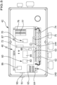
- the motor power supply unit 34 is directly assigned a control unit 40, with which operating and status detection units for the refrigerant compressor 20 and also the refrigerant circuit 10 are operated in order to monitor the operation of the refrigerant compressor 20 on the one hand and to optimize it with regard to the operating conditions on the other hand ( Fig.2 ).
- the motor power supply unit 34 in turn comprises a housing 36 which is arranged directly on the electric drive unit 28, in particular on a drive housing 29 which accommodates the latter.
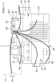
- control housing 42 of the control unit 40 which protects the control unit 40 by encapsulation in accordance with the respective protection requirements ( Fig.2 ), which interacts with the motor supply unit 34.
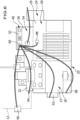
- the control housing 42 comprises a Fig.3 shown and sitting directly on the housing 36, which in particular represents a bottom of the control housing 42, wherein the housing base 44 is provided with a vibration-damping structure 46, for example a honeycomb structure, which rises above a housing bottom 48, in order to prevent vibrations of the drive housing 29 from being transmitted to the control unit 40 via the housing 36 of the motor supply unit 34.
- a vibration-damping structure 46 for example a honeycomb structure
- the housing base 44 is also provided with stiffeners 52 and 54, which are designed, for example, as stiffening webs 52, 54 rising above the housing bottom, on which the control unit 40 rests in the assembled state.
- the housing base 44 also has mounting recesses 56 for fixing the control unit 40.
- a grounding terminal block 58 is arranged on the housing base 44.
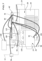
- the control unit 40 comprises, as in Fig.4 shown, in its basic version, a base module 60, which can be placed on a part of the stiffeners 52 and 54 and fixed to a part of the mounting holders 56.
- Connections 62 and 64 are provided on the base module 60 for carrying out basic functions, to which - as described in detail below - operating and/or status detection units can be connected.
- connections 62 are mains voltage connections, for example for alternating voltage
- connections 64 are low voltage connections, for example for direct voltage ( Fig.4 )
- mains voltage connections 62 can be switched by output stages 63 provided with switching units in order to switch operating units on or off.
- the low-voltage connections 64 are designed to operate condition detection units and are partially provided with switchable or controllable output stages 65 and furthermore some of the low-voltage connections 64 are used to record measured values of the condition detection units ( Fig.4 ).
- the base module 60 has an electrical connection element 66, with which, as in Fig.5 shown, an additional module 70 can be connected, which can also be inserted into the control housing 42 and can be arranged in addition to the base module 60 resting on the stiffeners 52 and 54 and can also be additionally mounted with another part of the mounting receptacles 56 on the housing base 44.
- the connection between the electrical connecting element 66 of the base module 60 and a corresponding electrical connecting element 72 of the additional module 70 is protected against mechanical stresses, in particular vibrations, in such a way that the electrical connection thus established through the connecting element 66 to the additional module 70 remains safe and reliable.
- the additional module 70 is also provided with electrical connections 74 and 76, via which a connection is made to operating and/or status detection units for carrying out additional functions.
- terminals 74 are mains voltage terminals, e.g. for alternating voltage, and terminals 76 are extra-low voltage terminals, e.g. for direct voltage.
- mains voltage connections 74 can be switched by output stages 75 provided with switching units and controlled by the base module 60 in order to switch operating units on or off.
- these mains voltage connections 74 are additionally protected in order to prevent further disruptions in the event of damage to an operating unit.
- At least one of the low-voltage connections 76 is designed to operate a state detection unit and, for example, provided with an output stage 77 that can be switched or controlled by the base module 60 and, furthermore, part of the low-voltage connections 76 are used to record and forward measured values from condition detection units to the base module 60.
- both the base module 60 and the additional module 70 are connected to the earth connection block 58 for earthing.
- control unit 40 can be designed in a first embodiment such that it only has the base module 60 and is thus only capable of executing the basic functions.
- the communication between the base module 60 and the system controller 30 takes place, for example, either analogously or by means of a BUS system via a BUS connection 140.
- each base module 60 is advantageously provided with a wireless communication unit 86 which transmits and receives information and/or data, for example via Bluetooth or WiFi.
- the basic functions can now be expanded to include operating and/or status detection units that perform additional functions by installing an additional module 70, which can be designed and combined depending on the configuration of the additional module 70 and thus depending on the requirements for the respective refrigerant compressor 20 in the respective refrigerant circuit 10.
- the base module 60 is able to recognize such an additional module 70 as such.
- the base module 60 is preferably configured.
- the operation of the basic functions and the additional functions is carried out by at least one processor 82 already provided in the basic module 60 and at least one memory 84 associated with it using program code and data stored in the memory 84, such as reference values, operating state variables, etc., so that the respective additional module 70 only carries out an intermediary communication between the basic module 60 and the operating and condition monitoring units connected to the additional module 70 for executing the additional functions.
- the communication of the respective additional module 70 with the base module 60 takes place internally or externally, either wired analog or via a BUS connection.
- an internal connection between the base module 60 and the respective additional module 70 is made via the connecting elements 66 and 72.
- an external connection can be made via lines, for example between the exclusion units 140 and 144.
- a further alternative provides that the communication of the base unit 60 with the additional module 70 takes place wirelessly, between the communication unit 86 of the base module and the communication unit 87 of the respective additional module 70.
- Such mediated communication of the respective additional module 70 can not only involve a transmission of a signal, but also, if necessary, a signal conversion and/or a signal processing and/or an intelligent Signal conditioning and/or an evaluating signal processing or also a forwarding of a control signal for operating output stages 75 and 77 according to the control specifications of the base module 60.
- the additional module 70 will under no circumstances carry out evaluation and/or control functions. These are reserved for the at least one processor 82 in the base module 60.
- the respective additional modules 70 only serve to provide an optimal adaptation of a wide variety of operating and/or status detection units for the execution of the additional functions through the mediating communication, while the base module 60, based on the stored program code and the data, provides all evaluation and/or control options for the most diverse additional functions and thus for all combinations with additional modules 70.
- control unit 40 comprises only the base module 60, as in Fig.4 shown.
- the base module 60 controls a configurable start sequence of the electric drive unit 28 with the processor 82 by controlling the motor power supply unit 34, which has the switching elements required for the start sequence. This enables adaptation to a wide variety of drive units 28.
- a temperature sensor 88 for detecting the temperature of the electric drive unit 28 is connected to the base module 60, so that if the electric drive unit 28 overheats, the base module 60 can switch off the drive unit 28 by comparing the measured temperature with a stored reference value.
- a lubricant sensor 92 is connected to the base module 60, which is arranged on the compressor unit 26, for example on the front side of an outer housing 27 thereof, and as a lubricant level sensor optically detects a lubricant level in a drive chamber of the compressor unit 26.
- the signal indicating the lubricant level is evaluated by at least one processor of the base module 60 and, if it falls below a threshold value, causes the processor 82 to switch off the drive unit 28 in order to prevent damage to the compressor unit 26.
- a sensor 94 for monitoring a temperature of the compressed gas at the pressure connection 22 is connected to the base module 60, wherein the detected compressed gas temperature is also compared by the processor 82 of the base module 60 with a threshold value, if this is exceeded, for example if 150° Celsius is exceeded, the electric drive unit 28 is switched off.
- a warning threshold as an additional threshold, for example at 140° Celsius, so that the processor 82 of the base module generates a warning signal when the warning threshold is exceeded and transmits this, for example, to the system control 30.
- a high-pressure sensor 96 is connected to the base module 60, which, for example, detects the high pressure in the refrigerant circuit 10, in particular in the high-pressure line 12, so that the processor 82 can compare this high pressure with a threshold value and, if this threshold value is exceeded, either also switches off the drive unit 28 or at least transmits a warning signal to the system control 30.
- the base module 60 in turn controls one or more display units 90, which, for example, display a warning signal and/or a stop of the drive unit 28 due to an impermissible operating state detected by the processor 82 and/or the readiness of the control unit 40 to start and can be seen through a window 91 in the control housing 42 ( Fig.4 ).
- display units 90 for example, display a warning signal and/or a stop of the drive unit 28 due to an impermissible operating state detected by the processor 82 and/or the readiness of the control unit 40 to start and can be seen through a window 91 in the control housing 42 ( Fig.4 ).
- a lubricant heater 98 is provided in the compressor unit, which is operated by the base module 60 such that it heats the lubricant when the drive unit 28 is switched off and then, when the drive unit 28 is in operation again, switches off the heater for the lubricant in order to keep the lubricant at a desired viscosity.
- the base module 60 operates in particular the lubricant sensor 92, the compressed gas temperature sensor 94 and the high pressure sensor 96 with direct voltage, for example 12 volts or 24 volts.
- the base module 60 operates the lubricant heater 98 with mains voltage, for example 110 volts or 230 volts, wherein an internal or a separate mains supply is provided for the lubricant heater 98, which the processor 82 switches on or off by means of one of the output stages 63.
- mains voltage for example 110 volts or 230 volts
- the processor 82 switches on or off by means of one of the output stages 63.
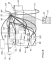
- control unit 40' includes these, as in Fig.5 shown, the basic module 60 and a first additional module 70.
- the base module 60 can be designed in the same way and connected to the same sensors 92, 94, 96 as in the first embodiment according to Fig.6 .
- a lubricant sensor 93 instead of the lubricant sensor 92, which is designed as a continuous level sensor and enables precise detection of the lubricant level.
- a lubricant injection 102 connected to the additional module 70 is also provided, which injects lubricant according to the lubricant level measured by the lubricant sensor 93, which comes from a lubricant separator 104, which is arranged in the high-pressure line 12 of the refrigerant circuit 10 following the pressure connection 22, so that the processor 82 supplies lubricant from the lubricant separator 104 to the compressor unit 26 through the lubricant injection 102, for example at defined intervals, according to the lubricant level determined by the lubricant sensor 93, this being done by taking advantage of the fact that the lubricant in the lubricant separator 104 is under high pressure and can therefore be easily injected into the drive chamber of the compressor unit 26 due to the high pressure.
- a power control unit 106 assigned to at least one cylinder bank 105 of the compressor unit 26 is connected to the additional module 70, which in particular comprises at least one power control valve which, for example, interrupts a supply of refrigerant to an intake chamber in the cylinder bank 105 or short-circuits an outlet chamber with the corresponding intake chamber, so that this cylinder bank 105 does not contribute any mass flow to the mass flow generated by the refrigerant compressor 20.
- the control of the at least one power control unit 106 or several power control units 106 is carried out by the processor 82 of the base module 60, which transmits the control signals to the additional module 70, which then carries out the respective control of the at least one power control unit 106.
- the processor 82 of the base module 60 reacts, for example, to request signals from the system controller 30, which requests the required mass flow in the refrigerant circuit 10.
- the additional module 70 controls a head fan 108, which represents a blower that serves for blower cooling of cylinder heads, for example the cylinder banks 105, of the compressor unit 26 in order to prevent overheating of the compressor in the area of the cylinder heads and in particular the pressure connection 22.
- a head fan 108 represents a blower that serves for blower cooling of cylinder heads, for example the cylinder banks 105, of the compressor unit 26 in order to prevent overheating of the compressor in the area of the cylinder heads and in particular the pressure connection 22.
- an injection unit 110 for liquid refrigerant is arranged on the refrigerant compressor 20 such that it cools the refrigerant sucked in by the compressor unit 26 in the region of suction chambers thereof by expansion in order to reduce the discharge gas temperature.
- This injection unit 110 is connected to the additional module 70 and is controlled, for example, by the processor 82 of the base module 60 when evaluating the compressed gas temperature at the compressed gas connection 22 in the same way as the head fan 108.
- a third embodiment of the control unit 40" shown in Fig.8
- the base module 60 is designed as in connection with the second embodiment according to Fig.7 described
- the additional module 70 is connected to the same units as the additional module 70 according to Fig.7
- the additional module 70' is connected to further power control units 106' and 106" in addition to the power control unit 106 in order to carry out a more precise power control and also to achieve a start-up relief also by at least one of the power control units 106, 106' and 106".
- the power control units 106 or 106, 106' and 106" are preferably used so that a power control between 10% and 100% of the mass flow is possible.
- the power control also includes monitoring of the refrigerant compressor 20 based on the signal from the discharge gas temperature sensor 94 alone, which, when a threshold value for the discharge gas temperature is exceeded, causes the processor 82 to increase the mass flow through the refrigerant compressor 20 by appropriately controlling the power control unit 106 or the power control units 106, 106' and 106" in accordance with a predetermined operating program stored in the memory 84, in order to thereby lower the discharge gas temperature again.
- the additional module 70' is also connected to a suction gas temperature sensor 112, which detects the temperature of the sucked-in refrigerant, which can then be transmitted to the base module 60 via the additional module 70'.
- the processor 82 is able to compare the suction gas temperature with a threshold value to check whether it is high enough so that no liquid refrigerant enters the compressor unit 26 of the refrigerant compressor 20 and to transmit a warning signal to the system controller 30 if the suction gas temperature is too low.
- the processor 82 compares both the suction gas temperature measured by the suction gas temperature sensor 112 and the discharge gas temperature measured by the discharge gas temperature sensor 94 with the operating limits E for the operation of the refrigerant compressor 20 defined in the memory 84.
- E values from a high pressure sensor and a suction pressure sensor it is possible to use E values from a high pressure sensor and a suction pressure sensor to monitor the application limits.
- Such application limits E are, for example, as in Fig.9 shown, an application limit E1, which causes the processor 82 to report a warning to the system controller 30.
- an operating limit E2 is provided which results in the refrigerant compressor 20 being switched off if the refrigerant compressor 20 is not operated within the operating limit E1 again within a certain period of time, or an operating limit E3 is provided which results in the refrigerant compressor 20 being switched off immediately by the processor 82.
- an operational limit E4 is provided, below which all previous warnings based on exceeding the operational limits E1 or E2 are deleted.
- the additional module 70' is also connected to an ambient temperature sensor 114, which reports an ambient temperature to the processor 82 so that the processor is able to further monitor the operating conditions for the refrigerant compressor 20 and adapt them if necessary.
- the processor 82 may switch on the blower unit 32 of the high-pressure side heat exchanger 14 by comparing the ambient temperature with stored reference values and by connecting the additional module 70' to the blower unit 32.
- the second embodiment of the additional module 70' also provides that it can be controlled by means of the lubricant sensor 92, described in connection with the exclusive use of the base module according to Fig.6 , additionally monitors a lubricant level.
- the base module 60 is identical to that in the first embodiment of the control unit 40 according to the invention.
- the lubricant sensor 91 is a lubricant differential pressure sensor which detects a pressure difference in the lubricant supply of the compressor unit 26 and thus transmits values regarding the quality of the lubricant supply of the compressor unit 20 to the base module 60.
- the processor 82 If the processor 82 detects a deficit in the lubricant supply by comparing it with reference values stored in the memory 84, the processor 82 temporarily operates the refrigerant compressor 20 at full load, i.e. maximum mass flow, in order to achieve sufficient lubricant return.
- the additional module 70" is further designed such that it is connected to the power control unit 106 and to the suction gas temperature sensor 112, and as a result the processor 82 of the base module 60 is able, on the one hand, to compare the suction gas temperature with a threshold value and, on the other hand, to determine whether the refrigerant compressor 20 is operated within the range of its operating limits E1 to E4.
- the additional module 70" is connected to the ambient temperature sensor 114 and thus the processor 82 of the base module 60 is able to operate the blower unit 32 taking into account the ambient temperature and, if necessary, the high pressure.
- this additional module 70" it is possible to connect this additional module 70" to a cooling point temperature sensor 116, which detects the temperature of the point to be cooled by the low-pressure side heat exchanger 18 and thus, when this temperature is transmitted by the additional module 70" to the processor 82 of the base module 60, opens up the possibility that the processor 82 temporarily or permanently takes over the control functions of the refrigerant circuit, in particular the system control 30, and controls the performance of the refrigerant compressor 20, in particular its mass flow, according to the temperature measured by the cooling point temperature sensor 116 under specification of a control program stored in the memory 84.
- a cooling point temperature sensor 116 which detects the temperature of the point to be cooled by the low-pressure side heat exchanger 18 and thus, when this temperature is transmitted by the additional module 70" to the processor 82 of the base module 60, opens up the possibility that the processor 82 temporarily or permanently takes over the control functions of the refrigerant circuit, in particular the system control 30, and controls the performance of the refrigerant compressor 20, in particular its mass flow,
- the additional module 70" is connected to a display of a lubricant return operation 118, which makes it possible to return lubricant to the refrigerant compressor 20 by operating the refrigerant compressor 20 at full load, i.e. with maximum mass flow, for a predetermined period of time by means of the processor 82 and a lubricant return program stored in the memory 84.
- the lubricant return operation is initiated by the processor 82 when a lubricant deficit is detected by one of the lubricant sensors on the part of the processor 82.
- the additional module 70" is connected to a mass flow control unit 122, which is arranged on the high-pressure side of the expansion element 15 and allows the mass flow flowing through the expansion element 15 to be controlled by the processor 82 according to a control program specified in the memory 84.
- the additional module 70" is also connected to a display unit 124, which serves to indicate whether any damaging operating state has been detected by the processor 82 or whether the refrigerant compressor 20 is operating without an alarm and, if necessary, to the display 118 for indicating whether the refrigerant compressor 20 is temporarily operating at full load for lubricant return.
- a fifth embodiment of a refrigerant compressor 20" according to the invention is shown in Fig. 11 , is provided with a frequency converter 130 for the electric drive unit 28, which in this embodiment of the control unit 40 ⁇ is connected to the base module 60, for example via the BUS connection unit 140, preferably via its BUS connection 142 and can thus be controlled by the processor 82, so that the mass flow of the refrigerant and thus the performance of the refrigerant compressor 20 in the refrigerant circuit 10 can be controlled by means of the frequency converter 130.
- control unit 40""' shown in Fig. 12 , it may be provided to operate the frequency converter 130 in addition to one or more of the operating units or status detection units described above via the respective additional module 70, for example the BUS connection unit 144, in which case operation of the power control units 106 for controlling the mass flow in this refrigerant compressor 20" may be omitted or may also be provided additionally if necessary.
- control unit 40 communication between the latter and the system controller 30 takes place either via a direct line or via the BUS connection unit 140 or via the wireless communication unit 86 of the respective base module 60.
- the BUS connection units 140 and 144 as well as the communication units 86, 87 serve in particular not only for communication with the system control 30, but can also be used for communication with other base modules 60 or additional modules 70 or configuration or readout units in order to read in or read out program code and/or data.
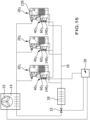
- the refrigerant circuit 10 comprises only one refrigerant compressor 20.
- a first possibility for communication between the system controller 30 and the control units 40 1 , 40 2 and 40 3 provides that the system controller 30 transmits a start/stop signal in analog or digital form and a setpoint specification in analog form to each of the control units 40 1 , 40 2 and 40 3 , so that the signal controller 30 of each of the control units 40 1 , 40 2 and 40 3 controls the respective refrigerant compressor in accordance with these specifications.
- the refrigerant compressor 20 and the refrigerant circuit 10 are designed in the same way as in the preceding embodiments.
- this embodiment is designed in the same way as the embodiment according to Fig. 13 .
- the communication between the refrigerant compressors 20 1 , 20 2 , 20 3 is identical to the previous embodiment according to Fig. 14 , however, for example, one of the refrigerant compressors 20 1 , 20 2 , 20 3 or several of them are provided with a frequency converter 130 which is controlled via the control unit 40 1 , 40 2 , 40 3 assigned to this refrigerant compressor 20 1 , 20 2 , 20 3 .
Landscapes
- Engineering & Computer Science (AREA)
- Mechanical Engineering (AREA)
- General Engineering & Computer Science (AREA)
- Physics & Mathematics (AREA)
- Thermal Sciences (AREA)
- Computer Hardware Design (AREA)
- Compressor (AREA)
- Control Of Positive-Displacement Pumps (AREA)
Applications Claiming Priority (1)
| Application Number | Priority Date | Filing Date | Title |
|---|---|---|---|
| DE102022131405.7A DE102022131405A1 (de) | 2022-11-28 | 2022-11-28 | Kältemittelkreislauf und Kältemittelverdichter |
Publications (2)
| Publication Number | Publication Date |
|---|---|
| EP4375509A1 true EP4375509A1 (fr) | 2024-05-29 |
| EP4375509B1 EP4375509B1 (fr) | 2026-04-29 |
Family
ID=88923672
Family Applications (1)
| Application Number | Title | Priority Date | Filing Date |
|---|---|---|---|
| EP23211431.4A Active EP4375509B1 (fr) | 2022-11-28 | 2023-11-22 | Circuit de réfrigérant et compresseur de réfrigérant |
Country Status (4)
| Country | Link |
|---|---|
| US (1) | US20240175616A1 (fr) |
| EP (1) | EP4375509B1 (fr) |
| CN (1) | CN117605663A (fr) |
| DE (1) | DE102022131405A1 (fr) |
Citations (4)
| Publication number | Priority date | Publication date | Assignee | Title |
|---|---|---|---|---|
| EP2917584B1 (fr) * | 2012-09-25 | 2017-12-20 | Emerson Climate Technologies, Inc. | Compresseur ayant un module de commande et de diagnostic |
| US9876346B2 (en) * | 2012-01-11 | 2018-01-23 | Emerson Climate Technologies, Inc. | System and method for compressor motor protection |
| EP2207964B1 (fr) * | 2007-11-02 | 2018-12-12 | Emerson Climate Technologies, Inc. | Module de capteur pour compresseur |
| EP3133286B1 (fr) * | 2007-11-02 | 2019-12-18 | Emerson Climate Technologies, Inc. | Module de capteur de compresseur |
Family Cites Families (4)
| Publication number | Priority date | Publication date | Assignee | Title |
|---|---|---|---|---|
| US6302654B1 (en) | 2000-02-29 | 2001-10-16 | Copeland Corporation | Compressor with control and protection system |
| US20030077179A1 (en) | 2001-10-19 | 2003-04-24 | Michael Collins | Compressor protection module and system and method incorporating same |
| US8950206B2 (en) * | 2007-10-05 | 2015-02-10 | Emerson Climate Technologies, Inc. | Compressor assembly having electronics cooling system and method |
| US11553618B2 (en) * | 2020-08-26 | 2023-01-10 | PassiveLogic, Inc. | Methods and systems of building automation state load and user preference via network systems activity |
-
2022
- 2022-11-28 DE DE102022131405.7A patent/DE102022131405A1/de active Pending
-
2023
- 2023-11-22 EP EP23211431.4A patent/EP4375509B1/fr active Active
- 2023-11-27 US US18/519,512 patent/US20240175616A1/en active Pending
- 2023-11-28 CN CN202311607155.7A patent/CN117605663A/zh active Pending
Patent Citations (4)
| Publication number | Priority date | Publication date | Assignee | Title |
|---|---|---|---|---|
| EP2207964B1 (fr) * | 2007-11-02 | 2018-12-12 | Emerson Climate Technologies, Inc. | Module de capteur pour compresseur |
| EP3133286B1 (fr) * | 2007-11-02 | 2019-12-18 | Emerson Climate Technologies, Inc. | Module de capteur de compresseur |
| US9876346B2 (en) * | 2012-01-11 | 2018-01-23 | Emerson Climate Technologies, Inc. | System and method for compressor motor protection |
| EP2917584B1 (fr) * | 2012-09-25 | 2017-12-20 | Emerson Climate Technologies, Inc. | Compresseur ayant un module de commande et de diagnostic |
Also Published As
| Publication number | Publication date |
|---|---|
| CN117605663A (zh) | 2024-02-27 |
| US20240175616A1 (en) | 2024-05-30 |
| DE102022131405A1 (de) | 2024-05-29 |
| EP4375509B1 (fr) | 2026-04-29 |
Similar Documents
| Publication | Publication Date | Title |
|---|---|---|
| EP2545280B1 (fr) | Systeme de lubrification pour un compresseur à vis | |
| EP1538337B1 (fr) | Montage de protection contre les surcharges et procédé visant à réduire la consommation d'énergie pendant des fluctuations de tension | |
| DE10262088B4 (de) | Chirurgisches Motorensystem | |
| EP2024712A1 (fr) | Dispositif pour la transmission de valeurs de mesure | |
| DE102014114837A1 (de) | Kältemittelverdichter | |
| DE102019004070B4 (de) | Verfahren und elektronische Anordnung zum Überwachen einer Kühlwirkung einer Luftkühlvorrichtung | |
| DE102007056461A1 (de) | Heißwasserliefervorrichtung | |
| EP1177616B1 (fr) | Moteur a commutation electronique, en particulier pour une pompe a liquide | |
| EP4375509B1 (fr) | Circuit de réfrigérant et compresseur de réfrigérant | |
| EP2484494B1 (fr) | Outillage doté d'un capteur en fonction de la température | |
| DE102015103730A1 (de) | Kältemittelverdichteranlage | |
| EP2898596B1 (fr) | Installation de cyclage thermodynamique | |
| DE202007017691U1 (de) | Kühl- und/oder Gefriergerät | |
| EP2778423A1 (fr) | Agrégat de pompe centrifuge | |
| EP1073174A2 (fr) | Moteur électrique comprenant une auto-protection contre la surchauffe | |
| DE102020128059A1 (de) | Verfahren und Vorrichtung zum Überwachen einer Luftkühlvorrichtung | |
| DE102009054158A1 (de) | Hydraulischer Antrieb | |
| DE102007048510A1 (de) | Elektromotor-Pumpen-Einheit, sowie eine Hydraulikanordnung mit einer derartigen Einheit | |
| EP0759507A1 (fr) | Entraînement électrique, en particulier pour une pompe de circulation de chauffage | |
| DE102011001050B4 (de) | Temperatur-Schutzschaltung für Versorgungsspannungs-Schaltkreise von elektrischen Einrichtungen | |
| DE202017001925U1 (de) | Regeleinheit für Verdichter | |
| EP3355007B1 (fr) | Dispositif de ventilation d'appareil de réfrigération et appareil de réfrigération à très basse température | |
| DE102011009621B4 (de) | Steuerung für eine Wärmepumpe | |
| EP2205916A2 (fr) | Appareil frigorifique | |
| WO2013113431A1 (fr) | Armoire de commande équipée d'un dispositif de refroidissement |
Legal Events
| Date | Code | Title | Description |
|---|---|---|---|
| PUAI | Public reference made under article 153(3) epc to a published international application that has entered the european phase |
Free format text: ORIGINAL CODE: 0009012 |
|
| STAA | Information on the status of an ep patent application or granted ep patent |
Free format text: STATUS: THE APPLICATION HAS BEEN PUBLISHED |
|
| AK | Designated contracting states |
Kind code of ref document: A1 Designated state(s): AL AT BE BG CH CY CZ DE DK EE ES FI FR GB GR HR HU IE IS IT LI LT LU LV MC ME MK MT NL NO PL PT RO RS SE SI SK SM TR |
|
| STAA | Information on the status of an ep patent application or granted ep patent |
Free format text: STATUS: REQUEST FOR EXAMINATION WAS MADE |
|
| 17P | Request for examination filed |
Effective date: 20240808 |
|
| RBV | Designated contracting states (corrected) |
Designated state(s): AL AT BE BG CH CY CZ DE DK EE ES FI FR GB GR HR HU IE IS IT LI LT LU LV MC ME MK MT NL NO PL PT RO RS SE SI SK SM TR |
|
| P01 | Opt-out of the competence of the unified patent court (upc) registered |
Free format text: CASE NUMBER: APP_56737/2024 Effective date: 20241017 |
|
| STAA | Information on the status of an ep patent application or granted ep patent |
Free format text: STATUS: EXAMINATION IS IN PROGRESS |
|
| 17Q | First examination report despatched |
Effective date: 20250131 |
|
| GRAP | Despatch of communication of intention to grant a patent |
Free format text: ORIGINAL CODE: EPIDOSNIGR1 |
|
| STAA | Information on the status of an ep patent application or granted ep patent |
Free format text: STATUS: GRANT OF PATENT IS INTENDED |
|
| GRAJ | Information related to disapproval of communication of intention to grant by the applicant or resumption of examination proceedings by the epo deleted |
Free format text: ORIGINAL CODE: EPIDOSDIGR1 |
|
| STAA | Information on the status of an ep patent application or granted ep patent |
Free format text: STATUS: EXAMINATION IS IN PROGRESS |
|
| GRAP | Despatch of communication of intention to grant a patent |
Free format text: ORIGINAL CODE: EPIDOSNIGR1 |
|
| STAA | Information on the status of an ep patent application or granted ep patent |
Free format text: STATUS: GRANT OF PATENT IS INTENDED |
|
| INTG | Intention to grant announced |
Effective date: 20251110 |
|
| INTC | Intention to grant announced (deleted) | ||
| INTG | Intention to grant announced |
Effective date: 20251124 |
|
| GRAS | Grant fee paid |
Free format text: ORIGINAL CODE: EPIDOSNIGR3 |
|
| GRAA | (expected) grant |
Free format text: ORIGINAL CODE: 0009210 |
|
| STAA | Information on the status of an ep patent application or granted ep patent |
Free format text: STATUS: THE PATENT HAS BEEN GRANTED |
|
| AK | Designated contracting states |
Kind code of ref document: B1 Designated state(s): AL AT BE BG CH CY CZ DE DK EE ES FI FR GB GR HR HU IE IS IT LI LT LU LV MC ME MK MT NL NO PL PT RO RS SE SI SK SM TR |
|
| REG | Reference to a national code |
Ref country code: CH Ref legal event code: F10 Free format text: ST27 STATUS EVENT CODE: U-0-0-F10-F00 (AS PROVIDED BY THE NATIONAL OFFICE) Effective date: 20260429 |