EP4375588A1 - Kälteerzeugungsvorrichtung mit verbessertem einzelejektorkühlzyklus und verfahren zur kälteerzeugung davon - Google Patents
Kälteerzeugungsvorrichtung mit verbessertem einzelejektorkühlzyklus und verfahren zur kälteerzeugung davon Download PDFInfo
- Publication number
- EP4375588A1 EP4375588A1 EP23212500.5A EP23212500A EP4375588A1 EP 4375588 A1 EP4375588 A1 EP 4375588A1 EP 23212500 A EP23212500 A EP 23212500A EP 4375588 A1 EP4375588 A1 EP 4375588A1
- Authority
- EP
- European Patent Office
- Prior art keywords
- ejector
- compression member
- working fluid
- branch
- reversible compression
- Prior art date
- Legal status (The legal status is an assumption and is not a legal conclusion. Google has not performed a legal analysis and makes no representation as to the accuracy of the status listed.)
- Pending
Links
Images




Classifications
-
- F—MECHANICAL ENGINEERING; LIGHTING; HEATING; WEAPONS; BLASTING
- F25—REFRIGERATION OR COOLING; COMBINED HEATING AND REFRIGERATION SYSTEMS; HEAT PUMP SYSTEMS; MANUFACTURE OR STORAGE OF ICE; LIQUEFACTION SOLIDIFICATION OF GASES
- F25B—REFRIGERATION MACHINES, PLANTS OR SYSTEMS; COMBINED HEATING AND REFRIGERATION SYSTEMS; HEAT PUMP SYSTEMS
- F25B1/00—Compression machines, plants or systems with non-reversible cycle
- F25B1/06—Compression machines, plants or systems with non-reversible cycle with compressor of jet type, e.g. using liquid under pressure
- F25B1/08—Compression machines, plants or systems with non-reversible cycle with compressor of jet type, e.g. using liquid under pressure using vapour under pressure
-
- F—MECHANICAL ENGINEERING; LIGHTING; HEATING; WEAPONS; BLASTING
- F25—REFRIGERATION OR COOLING; COMBINED HEATING AND REFRIGERATION SYSTEMS; HEAT PUMP SYSTEMS; MANUFACTURE OR STORAGE OF ICE; LIQUEFACTION SOLIDIFICATION OF GASES
- F25B—REFRIGERATION MACHINES, PLANTS OR SYSTEMS; COMBINED HEATING AND REFRIGERATION SYSTEMS; HEAT PUMP SYSTEMS
- F25B27/00—Machines, plants or systems, using particular sources of energy
- F25B27/002—Machines, plants or systems, using particular sources of energy using solar energy
- F25B27/005—Machines, plants or systems, using particular sources of energy using solar energy in compression type systems
-
- F—MECHANICAL ENGINEERING; LIGHTING; HEATING; WEAPONS; BLASTING
- F25—REFRIGERATION OR COOLING; COMBINED HEATING AND REFRIGERATION SYSTEMS; HEAT PUMP SYSTEMS; MANUFACTURE OR STORAGE OF ICE; LIQUEFACTION SOLIDIFICATION OF GASES
- F25B—REFRIGERATION MACHINES, PLANTS OR SYSTEMS; COMBINED HEATING AND REFRIGERATION SYSTEMS; HEAT PUMP SYSTEMS
- F25B41/00—Fluid-circulation arrangements
- F25B41/20—Disposition of valves, e.g. of on-off valves or flow control valves
Definitions
- the invention will find its application more particularly for cold production devices operating from a heat source at a low thermal level, for example of the order of 80°C to 150°C, potentially fluctuating, or even intermittent.
- the invention specifically relates to systems based on a single ejector refrigeration cycle. It will find applications for the production of stationary cold for industry or housing or applications for the production of even on-board cold.
- thermo compressor also called thermo compressor or ejector.
- Single ejector refrigeration cycles acronym SERS for Single Ejector Refrigeration System in English, use an ejector in place of a mechanical compressor.
- An ejector refrigeration cycle operates from thermal power supplied to a generator (Qgen) used to evaporate a working fluid at high pressure.
- the high-pressure, high-temperature steam known as the primary fluid, is expanded and used to entrain low-pressure secondary steam from an evaporator. It is the passage of secondary steam through the evaporator which produces the useful effect of the cycle.
- the secondary fluid evaporates in the evaporator, absorbing the thermal power of the environment (Qevap) which cools.
- Qevap thermal power of the environment
- This cycle presents a good COP (Coefficient of Performance), defined as Qevap//Qgen, around its design point, but if the generator pressure and/or the condenser pressure vary, the COP decreases sharply until a malfunction total of the machine.
- the ejectors ( Figure 1 ) are simple components, without moving parts, and inexpensive which make it possible to mix two incoming flows, a fluid 1 (the primary) at high pressure and another fluid 2 (the secondary) at low pressure, to produce an outgoing flow at intermediate pressure.
- the major limitation of ejectors is that, as they have no moving part, they have no possibility of regulation and therefore they lose a lot of efficiency. outside their nominal regime.
- the hot source in particular does not allow the ejector to operate in its nominal regime, which limits the development of this technology.
- the presence of the first reversible compression member at the ejector outlet makes it possible to precisely and effectively regulate the conditions at the ejector outlet, thus making it possible to operate as close as possible to its nominal speed.
- the presence of the first compression member makes it possible to adapt the operation of the ejector according to the conditions of the intermediate source ensuring the heat exchange with the condenser. So when the intermediate source which is advantageously ambient air heats up or cools down, the pressure in the condenser increases or decreases, moving the operation of the ejector away from its nominal speed and therefore its COP.
- the reversible expansion/compression member or the expansion member and the compression member thus allows, depending on the conditions of the intermediate source and therefore the operation of the condenser to compress or expand the fluid leaving the ejector so that it is as close as possible to the nominal operation of the ejector.
- the presence of the second reversible compression member at the inlet of the ejector makes it possible to precisely and effectively regulate the conditions at the inlet of the ejector, thus making it possible to operate as close as possible to its nominal speed.
- the presence of the second expansion/compression member makes it possible to adapt the operation of the ejector according to the conditions of the hot source ensuring the heat exchange with the generator. So when the hot source which is for example solar thermal energy heats up or cools down, the pressure in the generator increases or decreases, moving the operation of the ejector away from its nominal speed and therefore its COP.
- the reversible expansion/compression member or the expansion member and the compression member thus allows, depending on the conditions of the hot source and therefore the operation of the generator, to compress or expand the fluid entering the ejector to that it is as close as possible to the nominal operation of the ejector.
- the first reversible compression member arranged on the mixing branch and the second reversible compression member arranged on the driving branch are mechanically connected so that one reversible compression member mechanically drives the other reversible compression member.
- this allows that the organ which carries out an expansion of the working fluid mechanically drives the other organ responsible for carrying out compression.
- the cold production method according to the invention in which the device comprises a control module comprises a plurality of valves 301, 302, 303, 401, 402, 403 intended to control the circulation of the working fluid in the circuit fluidic and in particular in the second reversible compression member 400 and a plurality of sensors intended to measure predefined parameters on the fluidic circuit, the method comprising the measurement of predefined parameters on the fluidic circuit by sensors, the comparison of the measurements with values predefined and the alternative implementation of a compression mode or an expansion mode of the second reversible compression member or of a bypass of the second reversible compression member.
- the upstream and downstream, the inlet, the outlet, at a given point are taken with reference to the direction of circulation of the fluid.
- a parameter “substantially equal/greater/less than” or “of the order of” a given value we mean that this parameter is equal/greater/less than the given value, to within plus or minus 10%, or even to plus or minus 5% of this value.
- fluidically connected or “in fluidic connection” is understood to mean when a line provides a connection through or in which a fluid circulates.
- the expression "A fluidically connected to B” is synonymous with "A is in fluidic connection with B” and does not necessarily mean that there is no organ between A and B.
- the expressions " arranged on” or “on” are synonymous with “fluidically connected to”.
- these expressions mean a fluid connection between two elements, this connection which may or may not be direct. This means that it is possible that between a first element and a second element which are fluidically connected, a path of a fluid exists through one or more conduits, possibly an additional organ.
- the term “fluidically directly connected” means a direct fluidic connection between two elements. This means that between a first element and a second element which are fluidically directly connected no other element is present, other than one or more conduits.
- hot, cold, cooled we mean a relative temperature compared to another point in the system.
- An ejector refrigeration cycle also called a simple ejector refrigeration cycle (SERS) advantageously comprises a pump 101, a generator 102, an expander 103, an evaporator 104, a condenser 105 and an ejector 200.
- SERS simple ejector refrigeration cycle
- the refrigeration cycle comprises a fluid circuit making it possible to ensure the fluid connection of the different elements as well as the circulation of a working fluid.
- the fluidic circuit comprises a driving branch on which the pump 101 and the generator 102 are arranged.
- the driving branch extends from the inlet of the pump 101 to the primary fluid inlet 201 of the ejector 200.
- the motor branch operates at high pressure.
- the working fluid circulating in this driving branch is preferentially compressed by the pump 101.
- the pressure in the branches depends strongly on the working fluid. For example, using R600 as working fluid, the pressure in the power branch is of the order of 15 bars, for example between 10 bars (for a heat source at 80°C) and 35 bars ( for a heat source at 150°C).
- the fluidic circuit comprises a refrigeration branch on which the expander 103 and the evaporator 104 are arranged.
- the refrigeration branch extends from the inlet of the expander 103 to the secondary fluid inlet 202 of the ejector 200.
- the refrigeration branch operates at low pressure.
- the working fluid circulating in this refrigeration branch is preferentially expanded by the regulator 103.
- the pressure in the refrigeration branch is of the order of 1.5 bar, for example between 1 and 2 bars.
- the fluidic circuit comprises a mixing branch on which the ejector 200 and the condenser 105 are arranged.
- the mixing branch extends from the inlets 201, 202 of the ejector 200 to the outlet of the condenser 105.
- the mixing branch operates at intermediate pressure.
- the pressure in the mixing branch is of the order of 2 bars, for example between 2 and 2.5.
- the three branches of the fluidic circuit are arranged in parallel to each other.
- the fluidic circuit comprises a driving loop, or primary loop, comprising the driving branch and the mixing branch.
- the driving loop includes the ejector 200, the condenser 105, the expander 103 and the generator 102.
- the working fluid is here called the driving fluid or primary fluid.
- the working fluid exits in liquid form from the outlet of the condenser 105 and is then called engine fluid or engine working fluid here.
- the liquid working fluid is compressed by the pump 101 arranged on the driving branch to be sent into the generator 102. In the generator 102, the compressed liquid working fluid is vaporized, advantageously by transfer of thermal energy from a hot source.
- the motive fluid in the state of compressed vapor enters the ejector 200, via the primary fluid inlet 201.
- the ejector 200 is configured to create an acceleration of the motive fluid .
- the working fluid drives the steam from the refrigeration loop, thus allowing the mixing of the working fluid and the refrigerating fluid.
- the fluid mixed in the vapor state enters the condenser 105 to be condensed there.
- the fluidic circuit comprises a refrigeration loop, or secondary loop, comprising the refrigeration branch and the mixing branch.
- the refrigeration loop includes the ejector 200, the condenser 105, the expander 103 and the evaporator 104.
- the working fluid leaves in liquid form from the outlet of the condenser 105 and is then called refrigeration fluid or secondary fluid here.
- the liquid refrigerant fluid undergoes a preferentially isenthalpic expansion through the expander 103 before being routed to the evaporator 104 for the production of cold.
- the refrigerating working fluid is evaporated by recovering thermal energy from a source to be cooled.
- the source to be cooled is ambient air.
- the refrigerating working fluid is in the vapor state, preferably low pressure, which is sucked in by the working fluid in the ejector 200 via the secondary fluid inlet 202.
- the working fluid which is sent to the refrigerating branch corresponds to the working fluid which can be driven by the ejector and therefore which is not sucked up by the pump 101.
- the advantage of this refrigerating cycle with a simple ejector is to replace the work consumed by a compressor by a much lower work consumed by the pump 101, and by heat supplied to the generator 102 preferably at medium or high temperature.
- the working fluid is chosen from ammonia, water, HSC, HFO.
- the device according to the invention is particularly suitable for the use of hot sources from which the thermal energy comes from renewable energy such as solar thermal energy, geothermal energy, waste heat.
- the hot source brings a quantity of energy Q gen into the generator 102 for the benefit of the motor working fluid.
- the hot spring is at a temperature between 80 and 150°C.
- the temperature of the engine working fluid in the generator 102 is of the order of 100°C.
- the refrigerating working fluid evaporates using thermal energy from a source to be cooled.
- the source to be cooled is preferably the ambient fluid such as air.
- the source to be cooled brings a quantity of energy Q evap into the evaporator 104 for the benefit of the refrigerating working fluid.
- the source to be cooled is at a temperature between -20°C and 20°C.
- the temperature of the refrigerating working fluid in the evaporator 104 is of the order of 5°C.
- the mixed working fluid coming from the ejector in the vapor state is condensed to return to a liquid state at the outlet of the condenser 105.
- the condensation of the mixed working fluid is done by transfer of thermal energy from the working fluid mixed for the benefit of the environment and in particular an intermediate source.
- the quantity of thermal energy transmitted is Q cond .
- the intermediate source is the environment, such as ambient air.
- the intermediate source is at a temperature between 20 and 35°C.
- the temperature of the working fluid mixed in the condenser 105 is of the order of 20°C.
- the regulator 104 is advantageously an expansion valve.
- the ejector 200 is advantageously a steam ejector.
- the ejector 200 is chosen from a conventional ejector as illustrated in figure 1 or may be an ejector with variable sections known to those skilled in the art.
- the ejector 200 comprises the inlet of a primary fluid 201, the inlet of a secondary fluid 202, a sonic throat of the primary injector 203, a mixing chamber 204, a diffuser 205 and a fluid outlet of mixed work 206.
- the high pressure flow of the generator 102 accelerates into the inlet of the primary fluid 201 at the inlet of the sonic neck 203. This creates a low pressure at the outlet of the sonic neck 203.
- This low pressure is lower than the pressure at the outlet of the evaporator 104, the refrigerating working fluid in the vapor state comes from the evaporator 104 and is sucked into the ejector 200.
- the two flow rates are mixed.
- the speed of the mixture becomes supersonic which makes it possible to balance the pressure difference between the driving branch and the refrigerating branch then the speed of the mixture becomes subsonic in the diffuser 205 and the pressure of the fluid of mixed work adapts to the inlet pressure of condenser 105.
- the device according to the invention comprises, according to a first aspect, a first reversible compression member 300 arranged downstream of the ejector 200 and upstream of the condenser 105.
- the first reversible compression member 300 is arranged on the mixing branch.
- the first reversible compression member 300 is advantageously intended to maintain the operation of the ejector 200 in its nominal regime, in particular during variation in the conditions of the intermediate source at the condenser 105.
- the intermediate source extends a source advantageously coming from of the environment, it is subject to temperature variations which has repercussions on the operation of the condenser 105.
- the invention comprises the first reversible compression member 300 arranged between the outlet of the ejector 200 and the inlet of the condenser 105.
- the first reversible compression member 300 is configured to operate either in compressor mode or in expander mode.
- first reversible compression member 300 is meant a single member or a compression member and a distinct associated expansion member.
- reference is made to a reversible compression member without limitation for greater simplicity, but the description also applies to an embodiment in which the device comprises a first compression member and a first expansion member.
- the use of a first reversible compression member 300, consisting of a single member allows a saving in investment, mass and space by limiting the number of members in the thermodynamic system.
- the first reversible compression member 300 is advantageously chosen from positive displacement compressors. By this we mean that the compression of the fluid is done by reducing the volume of the compression chamber.
- the compression member is a piston, screw, scroll compressor also called a scroll compressor or rotary compressor.
- the first reversible compression member is advantageously associated with an electric motor or generator referenced 304.
- the cold production device advantageously comprises a control module comprising at least one, and preferably, a plurality of control valves arranged on the fluid circuit so as to control the circulation of the working fluid in the different branches and components of the device.
- the control module also comprises at least one, and preferably, a plurality of measuring elements such as temperature, pressure and flow sensors, arranged on the fluid circuit of the device.
- the device comprises a set of fluidic connections G, H, I, J, K, L, M, as well as valves 301.3 102.303 making it possible to control the circulation of the mixed working fluid between the outlet of the ejector 200 and the inlet of the condenser 105 and in particular through the first reversible compression member 300.
- the device comprises sensors ensuring the measurement of parameters on the fluidic circuit which are collected and analyzed by the control module so that the latter can control the circulation of the working fluid in the fluidic circuit, in particular by actuating the valves and the operation of the reversible compression member so as to alternately select the compression mode, the expansion mode, or the bypass of the reversible compression member.
- FIG. 2 illustrates the device according to this first aspect of the invention in which all of the fluidic connections are represented.
- the outlet of the condenser 105 is fluidly connected by a fluid connection A, preferably directly, to the inlet of the pump 101.
- the outlet of the pump 101 is fluidly connected by a fluid connection B, preferably directly, to the inlet of the generator 102.
- the output of the generator 102 is fluidly connected by a connection C, preferably directly, to the primary fluid inlet 201 of the ejector 200.
- the outlet of the condenser 105 is also fluidly connected by a fluidic connection D, preferably directly, to the inlet of the expander 103.
- the outlet of the expander 103 is fluidly connected by a fluidic connection E, preferably directly, to the inlet of the expander 103.
- the outlet of the evaporator 104 is fluidly connected by a fluidic connection F, preferably directly, to the secondary fluid inlet 202 of the ejector 200.
- the outlet 206 of the ejector 200 is fluidly connected, preferably directly, by a fluidic connection G to a valve 3-way valve 301.
- the 3-way valve 301 is fluidly connected, preferably directly, to the outlet 206 of the ejector 200 by the fluid connection G, to the 3-way valve 302 by the fluid connection H, and to the 3-way valve 303 by the fluidic connection L.
- the 3-way valve 302 is connected fluidically, preferably directly, to the 3-way valve 301 by the fluidic connection H, to the inlet of the condenser 105 by the fluidic connection M, to a first end of the first member reversible compression 300 by the fluid connection I.
- the 3-way valve 303 is fluidly connected, preferably directly, to the 3-way valve 301 by the fluid connection L, at a second end of the first reversible compression member 300 by the fluid connection J and at the inlet of the condenser 105 via the fluid connection K.
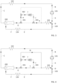
- the Figure 3 illustrates the device according to this first aspect of the invention according to a first embodiment in which the condenser is at a pressure greater than the design pressure of the ejector 200. It is here sought to compress the mixing fluid between the outlet 206 of the ejector 200 and the inlet of the condenser 105.
- the control module is thus configured to allow the circulation of the mixed working fluid in the first reversible compression member 300 operating in a compression mode.
- the control module is configured to direct the mixed working fluid exiting through the outlet 206 of the ejector 200 into the first reversible compression member 300 operating in compression mode and then to direct the compressed mixed working fluid towards the inlet of the condenser 105.
- the control module identifies a difference between the measured parameters and the target values. More precisely, the control module identifies that the pressure in the condenser 105 is greater than the target value of the design pressure of the ejector 200. The control module selects the compression mode to increase the pressure.
- the 3-way valve 301 is configured to direct the mixed working fluid to the fluid connection H, directing the mixed working fluid to the 3-way valve 302.
- the 3-way valve 302 is configured to direct the mixed working fluid to the fluid connection I.
- the mixed working fluid flows from the 3-way valve 302, preferably directly towards the first end of the first reversible compression member 300.
- the first reversible compression member 300 being in compression mode, the mixed working fluid is compressed.
- the mixed working fluid emerges from the first reversible compression member 300 through its second end.
- the compressed mixed working fluid leaving the first reversible compression member 300 circulates through the 3-way valve 303, preferably directly, via the fluid connection J.
- the 3-way valve 303 is configured to direct the compressed mixed working fluid into the fluid connection K, bringing the compressed mixed working fluid to the inlet of the condenser 105.
- FIG. 4 illustrates the device according to the first aspect of the invention according to a second embodiment in which the condenser is at a pressure lower than the design pressure of the ejector 200. It is here sought to relax the mixing fluid between the outlet 206 of the ejector 200 and the inlet of the condenser 105.
- the control module is thus configured to allow the circulation of the mixed working fluid in the first reversible compression member 300 operating in an expansion mode.
- the control module is configured to direct the mixed working fluid exiting through the outlet 206 of the ejector 200 into the first reversible compression member 300 operating in an expansion mode and then direct the expanded mixed working fluid toward the condenser inlet 105.
- control module identifies a difference between the measured parameters and the target values. More specifically, the control module identifies that the pressure in the condenser 105 is lower than the target value of the design pressure of the ejector 200. The control module selects the expansion mode to reduce the pressure
- the 3-way valve 301 is configured to direct the mixed working fluid to the fluid connection L, directing the mixed working fluid to the 3-way valve 303.
- the 3-way valve 303 is configured to direct the mixed working fluid to the fluid connection J.
- the mixed working fluid flows from the 3-way valve 303 preferably directly towards the second end of the first reversible compression member 300.
- the first reversible compression member 300 being in expansion mode, the mixed working fluid is expanded.
- the mixed working fluid emerges from the first reversible compression member 300 through its first end.
- the relaxed mixed working fluid leaving the first reversible compression member 300 circulates through the 3-way valve 302, preferably directly, via the fluid connection I.
- the 3-way valve 302 is configured to direct the relaxed mixed working fluid towards the fluid connection M, bringing the relaxed mixed working fluid to the inlet of the condenser 105.
- FIG. 5 illustrates the device according to this first aspect of the invention according to an embodiment in which the condenser 105 is at a pressure equivalent to the design pressure of the ejector 200. In this configuration, it is not necessary to act on the working fluid mixed between the outlet 206 of the ejector 200 and the inlet of the condenser 105.
- the control module is configured to direct mixed work from the outlet 206 of the ejector 200, preferably directly, towards the inlet of the condenser 105.
- the control module is configured to direct the mixed working fluid into a bypass of the first reversible compression member 300.
- the cycle illustrated in Figure 5 corresponds to a classic SERS single ejector refrigeration cycle.
- control module does not identify any difference between the measured parameters and the target values. More precisely, the control module identifies that the pressure in the condenser 105 corresponds to the target value of the design pressure of the ejector 200. The control module selects the bypass mode of the reversible compression member.
- the mixed working fluid exits through the outlet 206 of the ejector 200 then enters the 3-way valve 301, preferably directly, through the fluid connection G.
- the 3-way valve 301 is configured to direct the mixed working fluid to the fluid connection H, bringing the mixed working fluid to the 3-way valve 302.
- the 3-way valve 302 is configured to direct the mixed working fluid to the fluid connection M, bringing the mixed working fluid to the inlet of the condenser 105.
- the first reversible compression member 300 in compression mode is supplied with electrical energy coming for example from a battery or a conventional electrical network. In expansion mode, the first reversible compression member 300 is advantageously connected to a battery so as to store the electrical energy produced by the expansion of the mixed working fluid for later use.
- the device according to the invention comprises, according to a second aspect, a second reversible compression member 400 arranged upstream of the ejector 200 and downstream of the generator 102.
- the second reversible compression member 400 is arranged on the driving branch.
- the second reversible compression member 400 is advantageously intended to maintain the operation of the ejector 200 in its nominal regime, in particular during variations in the conditions of the hot source at the generator 102.
- the hot source being a source advantageously derived from of the environment, it is subject to temperature variations which has repercussions on the operation of the condenser 105.
- the invention comprises the second reversible compression member 400 arranged between the outlet of the generator 102 and the inlet 201 of the primary fluid of the ejector 200.
- the second reversible compression member 400 is configured to operate either in compressor mode or in expander mode.
- reversible compression member is meant a single member, or else a compression member and a separate expansion member instead of a single second reversible compression member.
- reference is made only to a reversible compression member for greater simplicity and without being limiting, but the description also applies to the embodiment in which the device comprises a second compression member and a second relaxation member.
- the use of a second reversible compression member 400 consisting of a single member allows a saving in investment, mass and space by limiting the number of members in the thermodynamic system.
- the second reversible compression member 400 is advantageously chosen from positive displacement compressors. By this we mean that the compression of the fluid is done by reducing the volume of the compression chamber.
- the compression member is a piston, screw, scroll compressor also called a scroll compressor or rotary compressor.
- a reversible compression member 300,400 makes it possible to operate alternately in compression relaxation mode as well as advantageously to have variable flow operation, through regulation of its rotation speed as well as its ability to operate over a range of compression ratio.
- the second reversible compression member is advantageously associated with an electric motor or generator referenced 404.
- the device comprises a set of fluidic connections N, O, P, Q, R, S, T, as well as valves 401, 402, 403 making it possible to control the circulation of the engine working fluid between the outlet of the generator 102 and the inlet 201 of the ejector 200 and in particular through the second reversible compression member 400.
- FIG. 6 illustrates the device according to this second aspect of the invention in which all of the fluidic connections are represented.
- the outlet of the condenser 105 is fluidly connected by a fluid connection A, preferably directly, to the inlet of the pump 101.
- the outlet of the pump 101 is fluidly connected by a fluid connection B, preferably directly, to the inlet of the generator 102.
- the output of the generator 102 is fluidly connected, preferably directly, by a connection N, to a 3-way valve 401.
- the 3-way valve 401 is fluidly connected, preferably directly, to the output of the generator 102 by the fluidic connection N, to the 3-way valve 402 by the fluid connection S, and to the 3-way valve 403 by the fluid connection O.
- the 3-way valve 402 is fluidly connected, preferably directly, to the 3-way valve 401 by the fluid connection S, to the inlet 201 of the primary fluid from the ejector 200 via the fluid connection R, to a second end of the second reversible compression member 400 via the fluid connection Q.
- the 3-way valve 403 is fluidly connected, preferably directly, to the valve 3 ways 401 by the fluidic connection O, at a first end of the second reversible compression member 400 by the fluidic connection P and at the inlet 200 of the primary fluid of the ejector 200 by the fluidic connection T.
- the outlet of the condenser 105 is also fluidly connected by a fluidic connection D, preferably directly, to the inlet of the expander 103.
- the outlet of the expander 103 is fluidly connected by a fluidic connection E, preferably directly, to the inlet of the evaporator 104.
- the outlet of the evaporator 104 is fluidly connected by a fluidic connection F, preferably directly, to the secondary fluid inlet 202 of the ejector 200.
- the outlet 206 of the ejector 200 is fluidly connected, preferably directly, by a fluidic connection U to the inlet of the condenser 105.
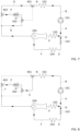
- FIG. 7 illustrates the device according to this second aspect of the invention according to a first embodiment in which the generator 102 is at a pressure greater than the design pressure of the ejector 200. It is here sought to relax the working fluid between the outlet of the generator 102 and the inlet 201 of the ejector 200.
- the control module is thus configured to allow the circulation of the working fluid in the second reversible compression member 400 operating in an expansion mode.
- the control module is configured to direct the working fluid leaving the generator 102 into the second reversible compression member 400 operating in an expansion mode and then directing the expanded working fluid towards the inlet 201 of the ejector 200.
- sensors measure parameters of the fluid circuit which are transmitted to the control module.
- the measured parameters are compared to target values by the control module.
- the control module selected the appropriate operating mode alternately compression mode, expansion mode, bypass of the reversible compression member.
- the control module identifies a difference between the measured parameters and the target values. More specifically, the control module identifies that the pressure in the generator 102 is greater than the target value of the design pressure of the ejector 200. The control module selects the expansion mode to reduce the pressure.
- the motor working fluid leaves the generator 102 then enters the 3-way valve 401, preferably directly, via the fluid connection N.
- the 3-way valve 401 is configured to direct the motor working fluid towards the fluid connection O, bringing the motor working fluid towards the 3-way valve 403.
- the 3-way valve 403 is configured to direct the motor working fluid towards the fluid connection P.
- the motor working fluid circulates from the 3-way valve 403, preferably directly towards the first end of the second reversible compression member 400.
- the second reversible compression member 300 being in expansion mode, the working fluid is expanded.
- the working working fluid emerges from the second reversible compression member 400 through its second end.
- the expanded working fluid leaving the second reversible compression member 400 circulates through the 3-way valve 402, preferably directly, via the fluidic connection Q.
- the 3-way valve 402 is configured to direct the expanded working fluid into the fluid connection R, bringing the relaxed engine working fluid to the inlet 201 of the ejector 200.
- the figure 8 illustrates the device according to the second aspect of the invention according to a second embodiment in which the generator 102 is at a pressure lower than the design pressure of the ejector 200. It is here sought to compress the mixing fluid between the output of the generator 102 and the inlet 201 of the ejector 200.
- the control module is thus configured to allow the circulation of the working fluid in the second reversible compression member 400 operating in a compression mode.
- the control module is configured to direct the working fluid exiting through the outlet of the generator 102 into the second reversible compression member 400 operating in a compression mode and then to direct the compressed working fluid towards the inlet 200 of the ejector 200.
- the control module identifies a difference between the measured parameters and the target values. More specifically, the control module identifies that the pressure in the generator 102 is lower than the target value of the design pressure of the ejector 200. The control module selects the compression mode to increase the pressure.
- the motor working fluid leaves through the outlet of the generator 102 then enters the 3-way valve 401, preferably directly, via the fluid connection N.
- the 3-way valve 401 is configured to direct the motor working fluid towards the connection fluid S, bringing the engine working fluid to the 3-way valve 402.
- the 3-way valve 402 is configured to direct the engine working fluid towards the fluid connection Q.
- the engine working fluid circulates from the 3-way valve 402, preferably directly, towards the second end of the second reversible compression member 400.
- the second reversible compression member 400 being in compression mode, the working fluid is compressed.
- the compressed working fluid comes out of the second reversible compression member 400 through its first end.
- the compressed engine working fluid leaving the second reversible compression member 400 circulates through the 3-way valve 403, preferably directly, via the fluid connection P.
- the 3-way valve 403 is configured to direct the compressed engine working fluid towards the fluid connection T, bringing the compressed engine working fluid to the inlet 201 of the ejector 200.
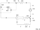
- FIG. 9 illustrates the device according to this second aspect of the invention according to an embodiment in which the generator 102 is at a pressure equivalent to the design pressure of the ejector 200. In this configuration, it is not necessary to act on the engine working fluid between the outlet of the generator 102 and the inlet 201 of the ejector 200.
- the control module is configured to direct the engine work from the outlet of the generator 102, preferably directly, towards the inlet 201 of the ejector 200.
- the control module is configured to direct the driving working fluid into a bypass of the second reversible compression member 400.
- the cycle illustrated in Figure 9 corresponds to a simple ejector refrigeration cycle, classic SERS.
- control module does not identify any difference between the measured parameters and the target values. More precisely, the control module identifies that the pressure in the generator 102 corresponds to the target value of the design pressure of the ejector 200. The control module selects the bypass mode of the reversible compression member.
- the mixed working fluid exits through the outlet of generator 102 then enters the 3-way valve 401, preferably directly, via the fluidic connection N.
- the 3-way valve 401 is configured to direct the driving working fluid towards the fluidic connection O, bringing the driving working fluid towards the 3-way valve 403
- the 3-way valve 403 is configured to direct the working fluid towards the fluid connection T, bringing the mixed working fluid to the inlet 201 of the ejector 200.
- the second reversible compression member 400 in. compression mode is supplied with electrical energy coming for example from a battery or a conventional electrical network.
- expansion mode the second reversible compression member 400 is advantageously connected to a battery so as to store the electrical energy produced by the expansion of the working fluid for subsequent use.
- the cold production device comprises the first reversible compression member 300 and the second reversible compression member 400. This third aspect of the invention is illustrated in the Figure 10 .
- This third aspect of the invention is particularly advantageous since it makes it possible to control both the pressure of the working fluid at the inlet of the ejector and at the outlet of the ejector.
- the first reversible compression member 300 and the second reversible compression member 400 are connected.
- first reversible compression member 300 and the second reversible compression member 400 are associated with one another so that the work produced by one of the members supplies the other member.
- the first reversible compression member 300 and the second reversible compression member 400 are mechanically associated with one another.
- one organ mechanically drives the other organ.
- one of the two members 300,400 in expansion mode which expands the working fluid mechanically drives, preferably in rotation, the other member 300,400 in compression mode which compresses the working fluid .
- the first reversible compression member 300 and the second reversible compression member 400 are electrically associated with one another.
- a member 300,400 in expansion mode is associated with an electric generator and thus produces electricity which can either be directly used by the other member 300,400 in compression mode, or be stored in a battery for use subsequently by one or other of the organs 300,400.
- the cold production device comprises an additional expansion member 500.
- the additional expansion member 500 is intended to produce electricity alternatively or simultaneously with the production of cold.
- the additional expansion member 500 is advantageously arranged on a branch branch of the ejector 200. More precisely, the additional expansion member 500 is arranged so as to receive the motor working fluid.
- the additional expansion member 500 is arranged between the inlet 201 of the ejector 200 and the outlet 206 of the ejector 200, more precisely the inlet of the condenser 105.
- This fourth aspect of the invention can be combined with the first aspect and/or the second aspect of the invention as illustrated in the Figure 11 .
- the device comprises the fluid connections V, W, X, Y, Z, G1, G2 and preferably at least two valves 501,502.
- the 3-way valve 500 is fluidly connected, preferably directly, to the 3-way valve 402 by the fluid connection V, to the 3-way valve 403 by the fluid connection W, the first end of the additional expansion member 500 by the fluidic connection 'ai de, at the inlet of the condenser 105 via the fluidic connection Z.
- the working fluid leaves the 3-way valve 403 or the 3-way valve 402 and enters the 3-way valve 501 respectively via the fluid connection V or the fluid connection W.
- the driving working fluid leaves the 3-way valve 501 and enters through the first end into the additional expansion member 500, preferably directly, via the fluid connection the additional expansion member 500 thus producing electricity preferentially by an electric generator 503.
- the relaxed working fluid leaves the additional expansion member 500 via the second end which is in fluidic connection, preferably directly, with the 3-way valve 502 via the fluid connection Y.
- the expanded working fluid can then be transmitted directly to the condenser 105 via the fluid connection Z.
- the device and the associated method are configured to allow the co-production of electricity and cold.
- the three-way valve 401 allows fluid to flow to both the fluid connection, or line, S and the fluid connection, or line, O.
- the fluid connection S is then connected fluidly to the valve 402, then the valve 402 is fluidly connected to the valve 501 allowing at least partial circulation of the fluid at the outlet of the generator 102 in the additional expansion member 500 and thus producing electricity, as described below above.
- the fluid connection O is then fluidly connected 403 which is fluidly connected to the inlet in the ejector 200 by the fluid connection T, allowing at least partial circulation of the fluid at the outlet of the generator 102 in the ejector 200 and thus produce cold, as described above.
- the cold production device comprises a heat exchanger arranged between the mixing branch and the driving branch. More preferably, the heat exchanger is arranged so as to ensure heat transfer between the mixed working fluid circulating in the mixing branch and the driving working fluid circulating in the driving branch. More precisely, on the mixing branch the heat exchanger is arranged downstream of the ejector 200 and preferably upstream of the condenser 105, more specifically upstream of the first reversible compression member 300. More precisely, on the driving branch, the The heat exchanger is arranged upstream of the generator 102 and preferably downstream of the pump 101. This heat exchanger makes it possible to transfer part of the thermal energy of the mixed working fluid for the benefit of the driving working fluid. This heat exchanger is a kind of preheating of the engine working fluid. This arrangement has the advantages of reducing the thermal power to be supplied to the generator 102, of reducing the size of the generator 102, of reducing the size of the condenser 105.
- Table 1 - Rated operating point refrigeration cycle Component Typical configuration Generator 102 Hot source temperature: 100°C Overheating: 0°C Power recovered: 100kW Condenser 105 Intermediate source temperature: 20°C Evaporator 104 Source temperature to be cooled: 5° C Overheating: 0°C Pump 101 Flow rate: 765 kg/h, Yield: 80%, Power: 0.6 kW
- the geometric design of the ejector 200 for the design point of Table 1 is given in Table 2.
- the designation of the sections of the ejector 200 refers to the figure 2 .
- Table 3 shows the impact of variations in the temperature of the hot source at generator 102 and of the intermediate source at condenser 105 on the cycle of figures 5 Or 9 .
- Table 4 shows the impact of variations of the hot source at generator 102 and of the intermediate source at condenser 105 on the cycle of the Figure 10 .
- Table 5 presents the difference in cold production ⁇ Q evap (kW) and the difference in electricity production ⁇ W tot (kW) between the cycle of the Figure 10 and that of the figure 5 Or 9 .
- the device according to the invention produces 1.4 kW less cold than a conventional simple ejector cold production device, but makes it possible to produce 2.5 kW of additional electricity. This is interesting when the need for cold is constant since the cold production remains the same as in the design point, but additional electricity is produced. In fact, even in this case, the exergy efficiency of the cycle increases with the invention.
- the device according to the invention produces more cold (gain of 61.1kW, 53.38kW and 5.7kW) than a device without the invention, at the cost of greater electricity consumption (excess electricity consumption of 3.2kW, 3.8kW and 1.7kW respectively).
- the electrical COP of the additional cold production, COP elec,sup ⁇ Q evap / ⁇ W tot , is very high (19.14 in cases #2 and #6), and indeed the exegetical yield of the cycle also increases.
- the device according to the invention makes it possible to continue to satisfy the design cooling demand with the use of a modest additional electrical power, much more efficiently than a normal vapor compression cycle for example.
- the device according to the invention makes it possible to operate the cycle even though it would be stopped without the invention.
- the device according to the invention allows both to produce more cold (gain of 6.1kW and 5.9kW) while producing more electricity (gain of 4.6kW and 2kW respectively ).
- the device according to the invention is particularly useful in all cases where constant cold power is needed and there are heat sources with fluctuating temperatures.
- the device according to the invention allows the cycle to always operate in its design point, in some cases thanks to the very efficient use of a small electrical power, and in others even allowing the production of a small electrical power in addition to cold.
Landscapes
- Engineering & Computer Science (AREA)
- Physics & Mathematics (AREA)
- Mechanical Engineering (AREA)
- Thermal Sciences (AREA)
- General Engineering & Computer Science (AREA)
- Life Sciences & Earth Sciences (AREA)
- Sustainable Development (AREA)
- Sustainable Energy (AREA)
- Jet Pumps And Other Pumps (AREA)
Applications Claiming Priority (1)
| Application Number | Priority Date | Filing Date | Title |
|---|---|---|---|
| FR2212407A FR3142535B1 (fr) | 2022-11-28 | 2022-11-28 | Dispositif de production de froid comprenant un cycle de réfrigération à éjecteur simple amélioré et procédé de production de froid associé |
Publications (1)
| Publication Number | Publication Date |
|---|---|
| EP4375588A1 true EP4375588A1 (de) | 2024-05-29 |
Family
ID=85018236
Family Applications (1)
| Application Number | Title | Priority Date | Filing Date |
|---|---|---|---|
| EP23212500.5A Pending EP4375588A1 (de) | 2022-11-28 | 2023-11-28 | Kälteerzeugungsvorrichtung mit verbessertem einzelejektorkühlzyklus und verfahren zur kälteerzeugung davon |
Country Status (2)
| Country | Link |
|---|---|
| EP (1) | EP4375588A1 (de) |
| FR (1) | FR3142535B1 (de) |
Citations (4)
| Publication number | Priority date | Publication date | Assignee | Title |
|---|---|---|---|---|
| EP1289039A2 (de) * | 2001-09-03 | 2003-03-05 | Renault s.a.s. | Kühlungssystem mit Ejektor für elektrische Fahrzeuge |
| WO2010129801A1 (en) * | 2009-05-06 | 2010-11-11 | Gerald Allen Alston | Heat-powered vehicle cabin temperature control system |
| US20110247351A1 (en) * | 2010-04-13 | 2011-10-13 | Gerald Allen Alston | Mechanically Enhanced Ejector HVAC and Electric Power Generation System |
| US20160313032A1 (en) * | 2015-04-23 | 2016-10-27 | King Fahd University Of Petroleum And Minerals | Solar powered cooling system |
-
2022
- 2022-11-28 FR FR2212407A patent/FR3142535B1/fr active Active
-
2023
- 2023-11-28 EP EP23212500.5A patent/EP4375588A1/de active Pending
Patent Citations (4)
| Publication number | Priority date | Publication date | Assignee | Title |
|---|---|---|---|---|
| EP1289039A2 (de) * | 2001-09-03 | 2003-03-05 | Renault s.a.s. | Kühlungssystem mit Ejektor für elektrische Fahrzeuge |
| WO2010129801A1 (en) * | 2009-05-06 | 2010-11-11 | Gerald Allen Alston | Heat-powered vehicle cabin temperature control system |
| US20110247351A1 (en) * | 2010-04-13 | 2011-10-13 | Gerald Allen Alston | Mechanically Enhanced Ejector HVAC and Electric Power Generation System |
| US20160313032A1 (en) * | 2015-04-23 | 2016-10-27 | King Fahd University Of Petroleum And Minerals | Solar powered cooling system |
Also Published As
| Publication number | Publication date |
|---|---|
| FR3142535A1 (fr) | 2024-05-31 |
| FR3142535B1 (fr) | 2024-12-13 |
Similar Documents
| Publication | Publication Date | Title |
|---|---|---|
| BE1009557A5 (fr) | Methode et appareillage de prerefroidissement d'air avec dispositif de refrigeration a contact indirect. | |
| FR2899936A1 (fr) | Procede de rechauffage selectif d'air a l'entree d'un compresseur associe a une turbine a gaz et systeme de production d'electricite. | |
| WO2014076391A1 (fr) | Procédé et système de conditionnement d'air pour aéronef | |
| EP2764243A1 (de) | Verfahren und system zur umwandlung von meereswärmeenergie | |
| FR3025831B1 (fr) | Systeme de production d'energie basee sur un cycle de rankine | |
| EP3748137B1 (de) | System zur gleichzeitigen erzeugung von elektrischer energie und kalter wärmeenergie, und entsprechendes verfahren | |
| EP3748274B1 (de) | System zur gleichzeitigen erzeugung von elektrischer energie und kalter und heisser wärmeenergie, und entsprechendes verfahren | |
| FR3142535A1 (fr) | Dispositif de production de froid comprenant un cycle de réfrigération à éjecteur simple amélioré et procédé de production de froid associé | |
| EP1488843B1 (de) | Verfahren zur Behandlung von Rauchgasen | |
| EP3670854A1 (de) | System zur gleichzeitigen erzeugung von elektrischer energie und wärmeenergie mithilfe eines rankine-prozess-moduls | |
| EP4350129B1 (de) | System zur energieerzeugung mit einem organischen rankine-zyklus und integriertem absorptionszyklus | |
| US20190211734A1 (en) | Waste heat recovery apparatus and control method therefor | |
| WO2023152232A1 (fr) | Turbomachine de chauffage pour un système de conditionnement de carburant configuré pour alimenter un turbomoteur d'aéronef à partir de carburant issu d'un réservoir cryogénique | |
| WO2025191010A1 (fr) | Pompe à chaleur à très haute température et procédé de production de chaleur à très haute température | |
| EP4116640B1 (de) | System zur erzeugung von kälte und strom aus einer thermischen quelle mit niedriger temperatur, das eine regelung des verhältnisses zwischen kälte- und stromerzeugung ermöglicht | |
| FR2999281A1 (fr) | Installation et procede d'optimisation de fonctionnement d'une installation frigorifique | |
| FR3154438A1 (fr) | Systeme de production d’electricite comportant un dispositif autonome comportant un turbogenerateur | |
| FR2981144A1 (fr) | Turbo pompe a chaleur. | |
| FR3163109A1 (fr) | Machine thermique à trois températures de fonctionnement | |
| WO2024120762A1 (fr) | Procédé et installation de refroidissement d'un flux de fluide utilisateur | |
| FR3133404A1 (fr) | Système de suralimentation en air pour système de conditionnement de carburant et procédé d’utilisation | |
| EP4330603B1 (de) | Wärmepumpe und phasenwechselenergiespeichervorrichtung | |
| FR3154353A1 (fr) | Vehicule automobile electrique comportant un dispositif de prolongation d’autonomie comportant un turbogenerateur | |
| FR3042538A1 (fr) | Ensemble moteur a circuit de refroidissement optimise | |
| FR2788631A1 (fr) | Pile a combustible |
Legal Events
| Date | Code | Title | Description |
|---|---|---|---|
| PUAI | Public reference made under article 153(3) epc to a published international application that has entered the european phase |
Free format text: ORIGINAL CODE: 0009012 |
|
| STAA | Information on the status of an ep patent application or granted ep patent |
Free format text: STATUS: REQUEST FOR EXAMINATION WAS MADE |
|
| 17P | Request for examination filed |
Effective date: 20231128 |
|
| AK | Designated contracting states |
Kind code of ref document: A1 Designated state(s): AL AT BE BG CH CY CZ DE DK EE ES FI FR GB GR HR HU IE IS IT LI LT LU LV MC ME MK MT NL NO PL PT RO RS SE SI SK SM TR |
|
| RAP3 | Party data changed (applicant data changed or rights of an application transferred) |
Owner name: COMMISSARIAT A L'ENERGIE ATOMIQUE ET AUX ENERGIESALTERNATIVES |
|
| GRAP | Despatch of communication of intention to grant a patent |
Free format text: ORIGINAL CODE: EPIDOSNIGR1 |
|
| STAA | Information on the status of an ep patent application or granted ep patent |
Free format text: STATUS: GRANT OF PATENT IS INTENDED |