EP4375708A1 - Vorrichtung zur messung der bewegung eines fahrdrahtes einer freileitung beim durchgang eines pantographen - Google Patents
Vorrichtung zur messung der bewegung eines fahrdrahtes einer freileitung beim durchgang eines pantographen Download PDFInfo
- Publication number
- EP4375708A1 EP4375708A1 EP21950862.9A EP21950862A EP4375708A1 EP 4375708 A1 EP4375708 A1 EP 4375708A1 EP 21950862 A EP21950862 A EP 21950862A EP 4375708 A1 EP4375708 A1 EP 4375708A1
- Authority
- EP
- European Patent Office
- Prior art keywords
- emitter
- receiver
- contact wire
- reflective plate
- fixed
- Prior art date
- Legal status (The legal status is an assumption and is not a legal conclusion. Google has not performed a legal analysis and makes no representation as to the accuracy of the status listed.)
- Pending
Links
- 238000004458 analytical method Methods 0.000 claims abstract description 7
- 238000005259 measurement Methods 0.000 description 12
- 238000000034 method Methods 0.000 description 5
- 238000010276 construction Methods 0.000 description 4
- 230000014509 gene expression Effects 0.000 description 3
- 238000000354 decomposition reaction Methods 0.000 description 2
- 238000010191 image analysis Methods 0.000 description 2
- 230000003287 optical effect Effects 0.000 description 2
- 238000006467 substitution reaction Methods 0.000 description 2
- PCTMTFRHKVHKIS-BMFZQQSSSA-N (1s,3r,4e,6e,8e,10e,12e,14e,16e,18s,19r,20r,21s,25r,27r,30r,31r,33s,35r,37s,38r)-3-[(2r,3s,4s,5s,6r)-4-amino-3,5-dihydroxy-6-methyloxan-2-yl]oxy-19,25,27,30,31,33,35,37-octahydroxy-18,20,21-trimethyl-23-oxo-22,39-dioxabicyclo[33.3.1]nonatriaconta-4,6,8,10 Chemical compound C1C=C2C[C@@H](OS(O)(=O)=O)CC[C@]2(C)[C@@H]2[C@@H]1[C@@H]1CC[C@H]([C@H](C)CCCC(C)C)[C@@]1(C)CC2.O[C@H]1[C@@H](N)[C@H](O)[C@@H](C)O[C@H]1O[C@H]1/C=C/C=C/C=C/C=C/C=C/C=C/C=C/[C@H](C)[C@@H](O)[C@@H](C)[C@H](C)OC(=O)C[C@H](O)C[C@H](O)CC[C@@H](O)[C@H](O)C[C@H](O)C[C@](O)(C[C@H](O)[C@H]2C(O)=O)O[C@H]2C1 PCTMTFRHKVHKIS-BMFZQQSSSA-N 0.000 description 1
- 238000006073 displacement reaction Methods 0.000 description 1
- 230000000694 effects Effects 0.000 description 1
- 238000009434 installation Methods 0.000 description 1
- 238000012423 maintenance Methods 0.000 description 1
- 230000007246 mechanism Effects 0.000 description 1
- 230000002028 premature Effects 0.000 description 1
- 238000002310 reflectometry Methods 0.000 description 1
- 238000000926 separation method Methods 0.000 description 1
Images


Classifications
-
- G—PHYSICS
- G01—MEASURING; TESTING
- G01S—RADIO DIRECTION-FINDING; RADIO NAVIGATION; DETERMINING DISTANCE OR VELOCITY BY USE OF RADIO WAVES; LOCATING OR PRESENCE-DETECTING BY USE OF THE REFLECTION OR RERADIATION OF RADIO WAVES; ANALOGOUS ARRANGEMENTS USING OTHER WAVES
- G01S17/00—Systems using the reflection or reradiation of electromagnetic waves other than radio waves, e.g. lidar systems
- G01S17/88—Lidar systems specially adapted for specific applications
-
- B—PERFORMING OPERATIONS; TRANSPORTING
- B60—VEHICLES IN GENERAL
- B60M—POWER SUPPLY LINES, AND DEVICES ALONG RAILS, FOR ELECTRICALLY- PROPELLED VEHICLES
- B60M1/00—Power supply lines for contact with collector on vehicle
- B60M1/12—Trolley lines; Accessories therefor
- B60M1/28—Manufacturing or repairing trolley lines
-
- B—PERFORMING OPERATIONS; TRANSPORTING
- B61—RAILWAYS
- B61L—GUIDING RAILWAY TRAFFIC; ENSURING THE SAFETY OF RAILWAY TRAFFIC
- B61L27/00—Central railway traffic control systems; Trackside control; Communication systems specially adapted therefor
- B61L27/50—Trackside diagnosis or maintenance, e.g. software upgrades
- B61L27/53—Trackside diagnosis or maintenance, e.g. software upgrades for trackside elements or systems, e.g. trackside supervision of trackside control system conditions
-
- G—PHYSICS
- G01—MEASURING; TESTING
- G01S—RADIO DIRECTION-FINDING; RADIO NAVIGATION; DETERMINING DISTANCE OR VELOCITY BY USE OF RADIO WAVES; LOCATING OR PRESENCE-DETECTING BY USE OF THE REFLECTION OR RERADIATION OF RADIO WAVES; ANALOGOUS ARRANGEMENTS USING OTHER WAVES
- G01S17/00—Systems using the reflection or reradiation of electromagnetic waves other than radio waves, e.g. lidar systems
- G01S17/02—Systems using the reflection of electromagnetic waves other than radio waves
- G01S17/06—Systems determining position data of a target
- G01S17/08—Systems determining position data of a target for measuring distance only
-
- G—PHYSICS
- G01—MEASURING; TESTING
- G01S—RADIO DIRECTION-FINDING; RADIO NAVIGATION; DETERMINING DISTANCE OR VELOCITY BY USE OF RADIO WAVES; LOCATING OR PRESENCE-DETECTING BY USE OF THE REFLECTION OR RERADIATION OF RADIO WAVES; ANALOGOUS ARRANGEMENTS USING OTHER WAVES
- G01S17/00—Systems using the reflection or reradiation of electromagnetic waves other than radio waves, e.g. lidar systems
- G01S17/02—Systems using the reflection of electromagnetic waves other than radio waves
- G01S17/06—Systems determining position data of a target
- G01S17/08—Systems determining position data of a target for measuring distance only
- G01S17/10—Systems determining position data of a target for measuring distance only using transmission of interrupted, pulse-modulated waves
-
- G—PHYSICS
- G01—MEASURING; TESTING
- G01S—RADIO DIRECTION-FINDING; RADIO NAVIGATION; DETERMINING DISTANCE OR VELOCITY BY USE OF RADIO WAVES; LOCATING OR PRESENCE-DETECTING BY USE OF THE REFLECTION OR RERADIATION OF RADIO WAVES; ANALOGOUS ARRANGEMENTS USING OTHER WAVES
- G01S17/00—Systems using the reflection or reradiation of electromagnetic waves other than radio waves, e.g. lidar systems
- G01S17/02—Systems using the reflection of electromagnetic waves other than radio waves
- G01S17/06—Systems determining position data of a target
- G01S17/46—Indirect determination of position data
-
- G—PHYSICS
- G01—MEASURING; TESTING
- G01S—RADIO DIRECTION-FINDING; RADIO NAVIGATION; DETERMINING DISTANCE OR VELOCITY BY USE OF RADIO WAVES; LOCATING OR PRESENCE-DETECTING BY USE OF THE REFLECTION OR RERADIATION OF RADIO WAVES; ANALOGOUS ARRANGEMENTS USING OTHER WAVES
- G01S17/00—Systems using the reflection or reradiation of electromagnetic waves other than radio waves, e.g. lidar systems
- G01S17/02—Systems using the reflection of electromagnetic waves other than radio waves
- G01S17/06—Systems determining position data of a target
- G01S17/46—Indirect determination of position data
- G01S17/48—Active triangulation systems, i.e. using the transmission and reflection of electromagnetic waves other than radio waves
-
- G—PHYSICS
- G01—MEASURING; TESTING
- G01S—RADIO DIRECTION-FINDING; RADIO NAVIGATION; DETERMINING DISTANCE OR VELOCITY BY USE OF RADIO WAVES; LOCATING OR PRESENCE-DETECTING BY USE OF THE REFLECTION OR RERADIATION OF RADIO WAVES; ANALOGOUS ARRANGEMENTS USING OTHER WAVES
- G01S17/00—Systems using the reflection or reradiation of electromagnetic waves other than radio waves, e.g. lidar systems
- G01S17/87—Combinations of systems using electromagnetic waves other than radio waves
-
- G—PHYSICS
- G01—MEASURING; TESTING
- G01S—RADIO DIRECTION-FINDING; RADIO NAVIGATION; DETERMINING DISTANCE OR VELOCITY BY USE OF RADIO WAVES; LOCATING OR PRESENCE-DETECTING BY USE OF THE REFLECTION OR RERADIATION OF RADIO WAVES; ANALOGOUS ARRANGEMENTS USING OTHER WAVES
- G01S7/00—Details of systems according to groups G01S13/00, G01S15/00, G01S17/00
- G01S7/48—Details of systems according to groups G01S13/00, G01S15/00, G01S17/00 of systems according to group G01S17/00
- G01S7/481—Constructional features, e.g. arrangements of optical elements
-
- G—PHYSICS
- G01—MEASURING; TESTING
- G01S—RADIO DIRECTION-FINDING; RADIO NAVIGATION; DETERMINING DISTANCE OR VELOCITY BY USE OF RADIO WAVES; LOCATING OR PRESENCE-DETECTING BY USE OF THE REFLECTION OR RERADIATION OF RADIO WAVES; ANALOGOUS ARRANGEMENTS USING OTHER WAVES
- G01S7/00—Details of systems according to groups G01S13/00, G01S15/00, G01S17/00
- G01S7/48—Details of systems according to groups G01S13/00, G01S15/00, G01S17/00 of systems according to group G01S17/00
- G01S7/481—Constructional features, e.g. arrangements of optical elements
- G01S7/4811—Constructional features, e.g. arrangements of optical elements common to transmitter and receiver
- G01S7/4813—Housing arrangements
Definitions
- the present invention belongs to the field of measurement instruments used in the railway sector.
- the object of the present invention relates to an instrument which allows the contactless measurement of the vertical and/or transverse movement of the contact wire of an overhead line when the pantograph of a train passes.
- the aerial contact or overhead line system is used today for power distribution on railway lines.
- the connection between an overhead line and a vehicle is made through a pantograph, which must ensure uninterrupted sliding contact with the wire of the overhead line at high speeds.
- Figure 1 shows a perspective view of an overhead line segment of a railway line.
- the overhead line (200) is fixed to a pair of posts (300) and comprises three basic elements: a support wire (201), a contact wire (202), and droppers (203).
- the support wire (201) performs the function of reducing as much as possible the height variations of the contact wire (202) with respect to the tracks (400). To that end, it runs at a height that is greater than that of the contact wire (202) and is connected thereto by means of a series of droppers (203) of different lengths.
- This system facilitates obtaining a contact wire (202) with a much more uniform height than that which can be achieved by simply tensioning the wire mechanically.
- overhead lines which may lack a support wire and droppers are used in other fields such as, for example, in tramway networks.
- FIGS. 2 and 3 schematically show how the pantograph (100) exerts a certain upward pressure on the contact wire (202). As a result, the part of the contact wire (202) touching the pantograph (100) moves upward, with the corresponding dropper (203) being left under tension.
- the pantograph is unable to instantaneously follow the movement of the overhead line, causing contact discontinuities that lead to the appearance of electric arcs. This does not only imply a discontinuity in the power supply to the electric motors that drive the train, but also the premature wear of the pantograph and the overhead line.
- a measuring device of this type must comply with many restrictions, including respecting the kinematic gauge through which the train moves and also those related to the electrical voltage of the overhead line, known as the electrical gauge.
- a device for measuring the vertical displacement of the contact wire of the overhead line based on an artificial vision camera that captures the movement of the overhead line and determines the movement through advanced image analysis techniques is known today. This system is excessively rigid and vulnerable to weather effects, in addition to having a very high cost.
- a system based on the arrangement of a vertically-arranged linear potentiometer mechanically connected to the contact wire, such that the elevation of said contact wire causes a variation in the potentiometer, is also known. This system is very inaccurate and excessively invasive.
- Another known device is based on the application of optical fibres with Bragg gratings. This system is also very invasive and expensive.
- the present invention describes an improved device for measuring the movement of the contact wire which occurs when a pantograph passes that solves the preceding problems.
- the device is based on the optical analysis of a beam that travels back and forth between a fixed point and the contact wire of the overhead line, which allows determining the vertical movement of the contact wire.
- additional techniques for determining not only the vertical movement of the contact wire, but also the transverse movement.
- the device of the invention essentially comprises an emitter/receiver and a reflective plate that are directed towards each other, such that a light beam emitted by the emitter is reflected on the reflective plate and returns to the receiver.
- the emitter/receiver is mechanically fixed either to a fixed support or to the contact wire of the overhead line of which the movement is to be measured.
- the reflective plate is mechanically fixed to the other of either the fixed support or the contact wire of the overhead line of which the movement is to be measured. Therefore, an analysis of the light beam emitted by the emitter and received by the receiver after being reflected on the reflective plate allows obtaining the vertical and/or transverse movement of the contact wire which occurs when the pantograph passes.
- the emitter/receiver and the reflective plate can be in any position provided that one of them is fixed to a fixed point and the other is fixed to the contact wire.
- the main concept is that the distance travelled by the beam, and/or the point to which said beam returns in the emitter/receiver, changes depending on the vertical movement of said contact wire. Therefore, a relatively simple analysis based on geometric considerations relative to the distance travelled by the light beam, calculated by means of the time-of-flight thereof, or based on changes in the reflected intensity, allows deducing the vertical and/or transverse distance that the contact wire has moved.
- This configuration is advantageous because it prevents drawbacks relating to the use of devices requiring mechanical contact with the contact wire such as the linear potentiometers used in the prior art. Furthermore, the geometric analysis performed is less complex compared to the image analysis techniques used in the artificial vision camera-based systems of the prior art, as well as less sensitive to meteorological variables.
- the emitter/receiver is fixed to the fixed support and the reflective plate is fixed to the contact wire of the overhead line.
- This configuration is particularly advantageous because it prevents the need for wired electrical connections to the element fixed to the contact wire.
- the only wired connections of the device are connected to the emitter/receiver and can be readily channelled through the fixed support.
- a post of the type conventionally used for supporting the overhead line can be used simply as a fixed support.
- the only element fixed to the contact wire is the reflective plate which requires no connections and hardly any maintenance.
- the emitter/receiver is fixed to the fixed support in a position located above the contact wire and the reflective plate is fixed to an upper side of the contact wire of the overhead line.
- the light beam emitted by the emitter/receiver is essentially vertical, or as will be described below with respect to a more particularly preferred embodiment, it has a small inclination with respect to the vertical. Therefore, the reflective plate in this configuration is fixed on the contact wire in a position essentially parallel to a horizontal plane, or only with a small inclination with respect to the horizontal plane. This allows determining the distance between the sensor and the reflective plate to obtain the vertical movement of the contact wire which occurs when the pantograph passes.
- This configuration is particularly advantageous because the loads exerted by wind on the reflective plate are much lower than in other configurations in which the reflective plate has a greater inclination with respect to the horizontal or is contained in a vertical plane. A lower wind load reduces the lateral movement of the contact wire.
- the emitter/receiver is a time-of-flight sensor or reflectometer that emits a light beam which is contained in a plane perpendicular to the contact wire and vertically directed downwards towards the reflective plate. This allows determining the distance between the emitter/receiver and the reflective plate so as to directly obtain the vertical movement of the contact wire which occurs when the pantograph passes.
- the reflective plate is a flat plate fixed according to a horizontal plane to the contact wire.
- This configuration is particularly advantageous because it facilitates the calculation of the vertical movement of the contact wire, which is obtained almost directly from the calculation of the distance travelled by the light beam, in addition to the fact that the assembly is much simpler than in the preceding case.
- the device comprises two emitters/receivers made up of two time-of-flight sensors or precision reflectometers that emit light beams which are contained in a plane perpendicular to the contact wire and directed with an inclination with respect to the vertical towards two portions of the reflective plate respectively facing each of said emitters/receivers. Therefore, the light beams emitted by the emitters/receivers cross one another on their way back and forth between each emitter/receiver and the corresponding portion of the reflective plate.
- the reflective plate is formed by the two portions which are in the form of essentially rectangular flat plates inclined with respect to one another and connected by an edge fixed in parallel to the contact wire.
- This configuration is particularly advantageous because it allows determining not only the vertical movement, but also the transverse movement of the contact wire, in a relatively simple manner.
- the device comprises a first emitter/receiver made up of a time-of-flight sensor or reflectometer fixed to the fixed support in a position facing the reflective plate.
- the reflective plate is fixed to an upper side of the contact wire of the overhead line and contained in a vertical plane passing through said contact wire.
- the first emitter/receiver is located facing the reflective plate, in other words, on one side of the contact wire, such that its light beam strikes an upper edge of said reflective plate perpendicularly, such that only a portion of the light beam of the second emitter/receiver is reflected by the reflective plate when there is no movement of the contact wire.
- the vertical movement of the contact wire is determined depending on a change in the amount reflected by the reflective plate of the light beam emitted by the second emitter/receiver.
- This configuration may be advantageous due to a greater ease of installation, since the emitters/receivers are installed in a position on one side of the contact wire, which is more accessible than in the two preceding configurations.
- the device comprises a second emitter/receiver made up of a time-of-flight sensor or reflectometer which are fixed to the fixed support.
- the second emitter/receiver is located facing the reflective plate, in other words, also on one side of the contact wire, at a lower height than the first emitter/receiver, such that its light beam strikes a central portion of said reflective plate perpendicularly. In that sense, the distance between the first emitter/receiver and the reflective plate can be determined to obtain the transverse movement of the contact wire which occurs when the pantograph passes.
- This configuration is particularly advantageous because it allows determining not only the vertical movement, but also the transverse movement of the contact wire, in a relatively simple manner.
- time-of-flight sensor when used, it can be of any type provided that it is configured to emit pulsed infrared light.
- the device of the invention further comprises a shield arranged above the emitter/receiver in order to protect it.
- the emitter/receiver can be fixed to a lower surface of the shield.
- This configuration is advantageous because the overhead light of the sun may cause disturbances in the values of the light beam received by the emitter/receiver, negatively affecting the precision of the movement measurement or even, in the worst case, completely preventing the performance of measurements.
- the movement measurement mechanisms described in the horizontal and vertical configurations are interchangeable.
- the configuration of the device in its vertical configuration, with a reflective plate formed by two essentially V-shaped portions and with two emitters/receivers that emit light beams that cross one another may also be arranged in the horizontal configuration.
- the configuration of the device in its horizontal configuration in other words, with a reflective flat plate and two emitters/receivers located in different positions, such that one of them serves to measure the distance between the emitter/receiver and the reflective plate, and the other determines the movement of the reflective plate in a plane transverse to the direction of the emitted light based on changes in the amount of reflected light due to part of it no longer being reflected by said reflective plate, may also be arranged in a vertical configuration.
- the first embodiment is based on the use of one or more emitters/receivers, for example time-of-flight sensors, reflectometry sensors or, in any case, any type of sensor capable of emitting a light beam and of receiving it after reflection, for determining the distance between the emitter/receiver itself and the body on which the light beam has been reflected.
- These emitters/receivers are arranged at a greater height than the contact wire and a reflective plate fixed to the contact wire, such that the light beam or beams emitted downwards are reflected on the reflective plate and return to the emitter/receiver.
- this arrangement allows obtaining only the vertical movement, when only a single emitter/receiver is used, or the vertical and transverse movements, when two emitters/receivers are used.
- Figure 4 shows a perspective view of a configuration of a device (1) which comprises two emitters/receivers (2a, 2b), and which therefore allows determining both the vertical movement and the transverse movement of the contact wire (202) of the overhead line (200).
- the overhead line (100) is formed by a support wire (201) connected to the contact wire (202) through droppers (203).
- the pantograph (100) fixed to the train, moves along the overhead line (200) making contact with the lower part of the contact wire (202), thereby causing the movement thereof in the vertical and/or transverse direction.
- the device (1) of this first embodiment comprises two emitters/receivers (2a, 2b) fixed to a fixed support (300), which are not show in the figures, above the contact wire (202) of the overhead line (200).
- the two emitters/receivers (2a, 2b) are essentially fixed vertically above the contact wire (202), each of them being located slightly the same distance towards opposite sides of the vertical plane of the contact wire (202).
- Each of the emitters/receivers (2a, 2b) is configured to emit a light beam contained in a plane perpendicular to the contact wire (202) such that it passes through the vertical plane of the contact wire (202) until reaching a point located at a small lateral distance from the contact wire (202) itself on an opposite side of the vertical plane of the contact wire (202) with respect to that in which the emitter/receiver (2a, 2b) in question is located.
- Figure 5 shows a view contained in a plane perpendicular to the contact wire (202).
- the device (1) also comprises a reflective plate (3) fixed to an upper side of the contact wire (202).
- the reflective plate (3) is formed by two rectangular-shaped, non-coplanar, flat portions (3a, 3b) connected through one of the sides thereof, thereby forming an edge which is parallel to the contact wire (202).
- the reflective plate (3) can be fixed to the contact wire (202) by any way known in the art, for example by means of a clamp.
- Each of the portions (3a, 3b) of the reflective plate (3) therefore protrudes laterally from the contact wire (202) and has an inclination the normal of which is parallel to the direction of the light beam emitted by a respective emitter/receiver (2a, 2b).
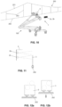
- the configuration of the reflective plate (3) is shown in detail in Figures 6a-6c .
- Figure 7 schematically shows the geometric configuration of the device (1) in a plane perpendicular to the contact wire (202).
- the objective is to establish the movement of point B, plus a vertical increment introduced by the clamp and the contact wire (202), in the vertical and horizontal axes with respect to the plane of assembly of the emitters/receivers (2a, 2b) with focal points S1 and S2.
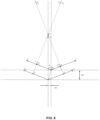
- the quadrilateral ABCD shown in Figure 8 is taken into account. This quadrilateral can be broken down into two triangles: ACD and BCD.
- Angles ACB ⁇ and ADB ⁇ are right angles by construction.
- CD 2 m 1 2 + m 2 2 ⁇ 2 m 1 m 2 cos ⁇
- BC m 1 ⁇ m 2 cos ⁇ sin ⁇
- Figure 9 shows a typical movement of the reflective plate (3) when a pantograph (100) passes with two positions of the portions (3a, 3b): EE' and E 0 E 0 '.
- the merit factor to be measured is movement B 0 B, and more precisely its decomposition in the horizontal and vertical axes of the assembly: ⁇ d and ⁇ h.
- angles of the hypotenuses with respect to the mentioned heights are, by construction, ⁇ /2.
- ⁇ h B 0 C 0 sin ⁇ 2 + ⁇ d 2 cos ⁇ 2 ⁇ BC sin ⁇ 2
- BC m 1 ⁇ m 2 cos ⁇ sin ⁇
- the internal angle of the sensors is ⁇ .
- ⁇ h 1 2 ⁇ d 1 ⁇ ⁇ d 2 cos ⁇ ⁇ 2 ⁇ sec ⁇ 2 ⁇ ⁇ + ⁇ d 2 cos ⁇ 2 ⁇ ⁇
- the reflective plate (3) is fixed to the contact wire (202) contained in a plane perpendicular to the horizontal and in the direction of the contact wire (202), and the pair of emitters/receivers (2a, 2b) is located facing the reflective plate (3) essentially perpendicular to said vertical plane.
- the pair of emitters/receivers (2a, 2b) is located on one side of the contact wire (202).
- the reflective plate (3) of this second embodiment is a flat plate.
- a first emitter/receiver (2a) is located at a height such that only a portion of the emitted light beam strikes the reflective plate (3) when it is in its rest position or non-vertically moved position when the pantograph of the train is not passing. Specifically, the light beam emitted by this first emitter (2a) strikes an area of the upper edge of the reflective plate, as shown in Figure 12a . In that sense, when the reflective plate (3) moves vertically upwards, the surface of the light beam striking the reflective plate (3) increases, as can be seen in Figure 12b , and therefore the intensity of the reflected light which returns to the first emitter/receiver (2a) itself also increases. This change in the light received by the first emitter/receiver (2a) allows determining the distance of vertical movement of the contact wire (202).
- the second emitter/receiver (2b) is located at a height such that all the emitted light beam strikes the reflective plate (3) regardless of the distance of vertical movement thereof. Therefore, all the light beam emitted by this second emitter/receiver (2b) returns to same, and it is possible to easily determine the distance between the reflective plate (3) and the emitter/receiver (2b), which corresponds to the transverse movement of the contact wire (202).
Landscapes
- Engineering & Computer Science (AREA)
- Physics & Mathematics (AREA)
- Electromagnetism (AREA)
- Radar, Positioning & Navigation (AREA)
- Computer Networks & Wireless Communication (AREA)
- General Physics & Mathematics (AREA)
- Remote Sensing (AREA)
- Mechanical Engineering (AREA)
- Manufacturing & Machinery (AREA)
- General Health & Medical Sciences (AREA)
- Biomedical Technology (AREA)
- Health & Medical Sciences (AREA)
- Current-Collector Devices For Electrically Propelled Vehicles (AREA)
Applications Claiming Priority (1)
| Application Number | Priority Date | Filing Date | Title |
|---|---|---|---|
| PCT/ES2021/070533 WO2023002068A1 (es) | 2021-07-19 | 2021-07-19 | Dispositivo de medida del desplazamiento del hilo de contacto de una catenaria al paso de un pantógrafo |
Publications (2)
| Publication Number | Publication Date |
|---|---|
| EP4375708A1 true EP4375708A1 (de) | 2024-05-29 |
| EP4375708A4 EP4375708A4 (de) | 2025-03-19 |
Family
ID=84978997
Family Applications (1)
| Application Number | Title | Priority Date | Filing Date |
|---|---|---|---|
| EP21950862.9A Pending EP4375708A4 (de) | 2021-07-19 | 2021-07-19 | Vorrichtung zur messung der bewegung eines fahrdrahtes einer freileitung beim durchgang eines pantographen |
Country Status (5)
| Country | Link |
|---|---|
| US (1) | US20240377536A1 (de) |
| EP (1) | EP4375708A4 (de) |
| CN (1) | CN117651884A (de) |
| CA (1) | CA3227113A1 (de) |
| WO (1) | WO2023002068A1 (de) |
Family Cites Families (8)
| Publication number | Priority date | Publication date | Assignee | Title |
|---|---|---|---|---|
| GB2176668B (en) * | 1985-05-28 | 1989-08-02 | Plessey Co Plc | Improvements relating to electric vehicle traction systems. |
| US6097298A (en) * | 1998-02-13 | 2000-08-01 | Ecsi Corporation | Apparatus and method of monitoring a power transmission line |
| ES2367067B1 (es) * | 2008-11-10 | 2012-09-03 | Telice Teléfonos, Líneas Y Centrales, S.A. | Auscultador de catenaria bimodal y sin contacto. |
| ES1099305Y (es) * | 2013-12-30 | 2017-01-04 | Telefonos Lineas Y Centrales S A Telice | Dispositivo de medicion, para medir, sin contacto, parametros de linea aerea de contacto |
| JP7523755B2 (ja) * | 2018-01-26 | 2024-07-29 | ラインビジョン,インコーポレイテッド | 送電線監視のシステムおよび方法 |
| CN110207597B (zh) * | 2019-06-27 | 2024-11-19 | 河南格通智能科技有限公司 | 一种非接触式接触网几何参数检测装置和检测方法 |
| CN110758423A (zh) * | 2019-10-30 | 2020-02-07 | 昆山高新轨道交通智能装备有限公司 | 轨网检测车的振动补偿方法、系统、设备及存储介质 |
| WO2021123463A1 (es) * | 2019-12-17 | 2021-06-24 | Telefonos, Lineas Y Centrales, S.A. | Procedimiento para captura y tratamiento in-situ y en tiempo real de parámetros geométricos de líneas ferroviarias |
-
2021
- 2021-07-19 EP EP21950862.9A patent/EP4375708A4/de active Pending
- 2021-07-19 CN CN202180100760.8A patent/CN117651884A/zh active Pending
- 2021-07-19 US US18/580,657 patent/US20240377536A1/en active Pending
- 2021-07-19 WO PCT/ES2021/070533 patent/WO2023002068A1/es not_active Ceased
- 2021-07-19 CA CA3227113A patent/CA3227113A1/en active Pending
Also Published As
| Publication number | Publication date |
|---|---|
| CN117651884A (zh) | 2024-03-05 |
| CA3227113A1 (en) | 2023-01-26 |
| US20240377536A1 (en) | 2024-11-14 |
| WO2023002068A1 (es) | 2023-01-26 |
| EP4375708A4 (de) | 2025-03-19 |
Similar Documents
| Publication | Publication Date | Title |
|---|---|---|
| US20130077083A1 (en) | Optical beam scanner and laser radar unit | |
| US9528818B2 (en) | Control method for producing ground markings, and reference beam generator | |
| JP6445383B2 (ja) | 軌道検測方法及びその装置 | |
| JP6576542B2 (ja) | 立体形状計測装置、立体形状計測プローブ | |
| CN108286997B (zh) | 一种激光跟踪测量系统及方法 | |
| EP4375708A1 (de) | Vorrichtung zur messung der bewegung eines fahrdrahtes einer freileitung beim durchgang eines pantographen | |
| PT2047210E (pt) | Digitalização óptica de perfis | |
| CN114521227B (zh) | 激光干涉测量系统及方法 | |
| CN103105282B (zh) | 一种对光纤阵列或芯片进行角度测量的装置及方法 | |
| WO2006005285A1 (de) | Abtastvorrichtung zum vermessen der konturen eines objektes | |
| CN108088375A (zh) | 一种物体相对位置检测光束接收方法及装置 | |
| CN108072325A (zh) | 一种物体位置确定方法及装置 | |
| US9255788B1 (en) | Measuring method for linear stage | |
| JPS59762B2 (ja) | 変位測定装置 | |
| HK40103870A (zh) | 用於在受电弓通过时测量架空线路的接触线的运动的装置 | |
| KR101604286B1 (ko) | 레이저 변위측정장치 | |
| CN110207597B (zh) | 一种非接触式接触网几何参数检测装置和检测方法 | |
| JP2005077096A (ja) | レールふく進測定装置及び測定方法並びに基準となるターゲットの設置方法 | |
| Vázquez et al. | Non-contact sensor for monitoring catenary-pantograph interaction | |
| CN119124008A (zh) | 非接触式的配电线路塔基位移测量光学装置及其测量方法 | |
| JPH0571921A (ja) | 光量式トロリー線摩耗測定装置 | |
| KR100195136B1 (ko) | 물체 표면 높이 측정장치 | |
| CN109751956A (zh) | 一种悬挂缆线测量方法及装置 | |
| JPS5865801A (ja) | 鉄道用工事機 | |
| JP2906081B2 (ja) | 光雨量計 |
Legal Events
| Date | Code | Title | Description |
|---|---|---|---|
| STAA | Information on the status of an ep patent application or granted ep patent |
Free format text: STATUS: THE INTERNATIONAL PUBLICATION HAS BEEN MADE |
|
| PUAI | Public reference made under article 153(3) epc to a published international application that has entered the european phase |
Free format text: ORIGINAL CODE: 0009012 |
|
| STAA | Information on the status of an ep patent application or granted ep patent |
Free format text: STATUS: REQUEST FOR EXAMINATION WAS MADE |
|
| 17P | Request for examination filed |
Effective date: 20240119 |
|
| AK | Designated contracting states |
Kind code of ref document: A1 Designated state(s): AL AT BE BG CH CY CZ DE DK EE ES FI FR GB GR HR HU IE IS IT LI LT LU LV MC MK MT NL NO PL PT RO RS SE SI SK SM TR |
|
| DAV | Request for validation of the european patent (deleted) | ||
| DAX | Request for extension of the european patent (deleted) | ||
| A4 | Supplementary search report drawn up and despatched |
Effective date: 20250214 |
|
| RIC1 | Information provided on ipc code assigned before grant |
Ipc: G01S 17/87 20200101ALI20250210BHEP Ipc: G01S 17/46 20060101ALI20250210BHEP Ipc: G01S 17/08 20060101ALI20250210BHEP Ipc: G01S 7/481 20060101ALI20250210BHEP Ipc: B61L 27/53 20220101ALI20250210BHEP Ipc: B60M 1/28 20060101ALI20250210BHEP Ipc: G01S 17/88 20060101ALI20250210BHEP Ipc: G01S 17/48 20060101AFI20250210BHEP |