EP4377093B1 - Bearbeitungsmaschinen sowie verfahren zur relativen ausrichtung eines substrates zu einem bearbeitungsaggregat in einer bearbeitungsmaschine - Google Patents
Bearbeitungsmaschinen sowie verfahren zur relativen ausrichtung eines substrates zu einem bearbeitungsaggregat in einer bearbeitungsmaschine Download PDFInfo
- Publication number
- EP4377093B1 EP4377093B1 EP23701660.5A EP23701660A EP4377093B1 EP 4377093 B1 EP4377093 B1 EP 4377093B1 EP 23701660 A EP23701660 A EP 23701660A EP 4377093 B1 EP4377093 B1 EP 4377093B1
- Authority
- EP
- European Patent Office
- Prior art keywords
- transport
- unit
- substrate
- processing
- elements
- Prior art date
- Legal status (The legal status is an assumption and is not a legal conclusion. Google has not performed a legal analysis and makes no representation as to the accuracy of the status listed.)
- Active
Links
Images




Classifications
-
- B—PERFORMING OPERATIONS; TRANSPORTING
- B41—PRINTING; LINING MACHINES; TYPEWRITERS; STAMPS
- B41F—PRINTING MACHINES OR PRESSES
- B41F19/00—Apparatus or machines for carrying out printing operations combined with other operations
- B41F19/008—Apparatus or machines for carrying out printing operations combined with other operations with means for stamping or cutting out
-
- B—PERFORMING OPERATIONS; TRANSPORTING
- B41—PRINTING; LINING MACHINES; TYPEWRITERS; STAMPS
- B41F—PRINTING MACHINES OR PRESSES
- B41F13/00—Common details of rotary presses or machines
- B41F13/08—Cylinders
- B41F13/10—Forme cylinders
- B41F13/12—Registering devices
- B41F13/14—Registering devices with means for displacing the cylinders
-
- B—PERFORMING OPERATIONS; TRANSPORTING
- B41—PRINTING; LINING MACHINES; TYPEWRITERS; STAMPS
- B41F—PRINTING MACHINES OR PRESSES
- B41F13/00—Common details of rotary presses or machines
- B41F13/54—Auxiliary folding, cutting, collecting or depositing of sheets or webs
- B41F13/56—Folding or cutting
-
- B—PERFORMING OPERATIONS; TRANSPORTING
- B41—PRINTING; LINING MACHINES; TYPEWRITERS; STAMPS
- B41F—PRINTING MACHINES OR PRESSES
- B41F21/00—Devices for conveying sheets through printing apparatus or machines
-
- B—PERFORMING OPERATIONS; TRANSPORTING
- B41—PRINTING; LINING MACHINES; TYPEWRITERS; STAMPS
- B41F—PRINTING MACHINES OR PRESSES
- B41F21/00—Devices for conveying sheets through printing apparatus or machines
- B41F21/08—Combinations of endless conveyors and grippers
-
- B—PERFORMING OPERATIONS; TRANSPORTING
- B41—PRINTING; LINING MACHINES; TYPEWRITERS; STAMPS
- B41F—PRINTING MACHINES OR PRESSES
- B41F21/00—Devices for conveying sheets through printing apparatus or machines
- B41F21/10—Combinations of transfer drums and grippers
- B41F21/102—Combinations of transfer drums and grippers with pneumatic means
-
- B—PERFORMING OPERATIONS; TRANSPORTING
- B41—PRINTING; LINING MACHINES; TYPEWRITERS; STAMPS
- B41F—PRINTING MACHINES OR PRESSES
- B41F33/00—Indicating, counting, warning, control or safety devices
-
- B—PERFORMING OPERATIONS; TRANSPORTING
- B41—PRINTING; LINING MACHINES; TYPEWRITERS; STAMPS
- B41F—PRINTING MACHINES OR PRESSES
- B41F33/00—Indicating, counting, warning, control or safety devices
- B41F33/0036—Devices for scanning or checking the printed matter for quality control
-
- B—PERFORMING OPERATIONS; TRANSPORTING
- B41—PRINTING; LINING MACHINES; TYPEWRITERS; STAMPS
- B41F—PRINTING MACHINES OR PRESSES
- B41F33/00—Indicating, counting, warning, control or safety devices
- B41F33/0081—Devices for scanning register marks
-
- B—PERFORMING OPERATIONS; TRANSPORTING
- B41—PRINTING; LINING MACHINES; TYPEWRITERS; STAMPS
- B41F—PRINTING MACHINES OR PRESSES
- B41F5/00—Rotary letterpress machines
- B41F5/24—Rotary letterpress machines for flexographic printing
-
- B—PERFORMING OPERATIONS; TRANSPORTING
- B65—CONVEYING; PACKING; STORING; HANDLING THIN OR FILAMENTARY MATERIAL
- B65H—HANDLING THIN OR FILAMENTARY MATERIAL, e.g. SHEETS, WEBS, CABLES
- B65H9/00—Registering, e.g. orientating, articles; Devices therefor
- B65H9/002—Registering, e.g. orientating, articles; Devices therefor changing orientation of sheet by only controlling movement of the forwarding means, i.e. without the use of stop or register wall
-
- B—PERFORMING OPERATIONS; TRANSPORTING
- B65—CONVEYING; PACKING; STORING; HANDLING THIN OR FILAMENTARY MATERIAL
- B65H—HANDLING THIN OR FILAMENTARY MATERIAL, e.g. SHEETS, WEBS, CABLES
- B65H9/00—Registering, e.g. orientating, articles; Devices therefor
- B65H9/10—Pusher and like movable registers; Pusher or gripper devices which move articles into registered position
- B65H9/103—Pusher and like movable registers; Pusher or gripper devices which move articles into registered position acting by friction or suction on the article for pushing or pulling it into registered position, e.g. against a stop
- B65H9/105—Pusher and like movable registers; Pusher or gripper devices which move articles into registered position acting by friction or suction on the article for pushing or pulling it into registered position, e.g. against a stop using suction means
-
- B—PERFORMING OPERATIONS; TRANSPORTING
- B65—CONVEYING; PACKING; STORING; HANDLING THIN OR FILAMENTARY MATERIAL
- B65H—HANDLING THIN OR FILAMENTARY MATERIAL, e.g. SHEETS, WEBS, CABLES
- B65H9/00—Registering, e.g. orientating, articles; Devices therefor
- B65H9/10—Pusher and like movable registers; Pusher or gripper devices which move articles into registered position
- B65H9/103—Pusher and like movable registers; Pusher or gripper devices which move articles into registered position acting by friction or suction on the article for pushing or pulling it into registered position, e.g. against a stop
- B65H9/106—Pusher and like movable registers; Pusher or gripper devices which move articles into registered position acting by friction or suction on the article for pushing or pulling it into registered position, e.g. against a stop using rotary driven elements as part acting on the article
-
- B—PERFORMING OPERATIONS; TRANSPORTING
- B65—CONVEYING; PACKING; STORING; HANDLING THIN OR FILAMENTARY MATERIAL
- B65H—HANDLING THIN OR FILAMENTARY MATERIAL, e.g. SHEETS, WEBS, CABLES
- B65H9/00—Registering, e.g. orientating, articles; Devices therefor
- B65H9/20—Assisting by photoelectric, sonic, or pneumatic indicators
-
- B—PERFORMING OPERATIONS; TRANSPORTING
- B41—PRINTING; LINING MACHINES; TYPEWRITERS; STAMPS
- B41P—INDEXING SCHEME RELATING TO PRINTING, LINING MACHINES, TYPEWRITERS, AND TO STAMPS
- B41P2200/00—Printing processes
- B41P2200/10—Relief printing
- B41P2200/12—Flexographic printing
-
- B—PERFORMING OPERATIONS; TRANSPORTING
- B65—CONVEYING; PACKING; STORING; HANDLING THIN OR FILAMENTARY MATERIAL
- B65H—HANDLING THIN OR FILAMENTARY MATERIAL, e.g. SHEETS, WEBS, CABLES
- B65H2301/00—Handling processes for sheets or webs
- B65H2301/30—Orientation, displacement, position of the handled material
- B65H2301/33—Modifying, selecting, changing orientation
- B65H2301/331—Skewing, correcting skew, i.e. changing slightly orientation of material
-
- B—PERFORMING OPERATIONS; TRANSPORTING
- B65—CONVEYING; PACKING; STORING; HANDLING THIN OR FILAMENTARY MATERIAL
- B65H—HANDLING THIN OR FILAMENTARY MATERIAL, e.g. SHEETS, WEBS, CABLES
- B65H2404/00—Parts for transporting or guiding the handled material
- B65H2404/10—Rollers
- B65H2404/15—Roller assembly, particular roller arrangement
- B65H2404/152—Arrangement of roller on a movable frame
- B65H2404/1523—Arrangement of roller on a movable frame moving in parallel to its axis
-
- B—PERFORMING OPERATIONS; TRANSPORTING
- B65—CONVEYING; PACKING; STORING; HANDLING THIN OR FILAMENTARY MATERIAL
- B65H—HANDLING THIN OR FILAMENTARY MATERIAL, e.g. SHEETS, WEBS, CABLES
- B65H2404/00—Parts for transporting or guiding the handled material
- B65H2404/10—Rollers
- B65H2404/16—Details of driving
- B65H2404/161—Means for driving a roller parallely to its axis of rotation, e.g. during its rotation
-
- B—PERFORMING OPERATIONS; TRANSPORTING
- B65—CONVEYING; PACKING; STORING; HANDLING THIN OR FILAMENTARY MATERIAL
- B65H—HANDLING THIN OR FILAMENTARY MATERIAL, e.g. SHEETS, WEBS, CABLES
- B65H2406/00—Means using fluid
- B65H2406/30—Suction means
- B65H2406/31—Suction box; Suction chambers
-
- B—PERFORMING OPERATIONS; TRANSPORTING
- B65—CONVEYING; PACKING; STORING; HANDLING THIN OR FILAMENTARY MATERIAL
- B65H—HANDLING THIN OR FILAMENTARY MATERIAL, e.g. SHEETS, WEBS, CABLES
- B65H2406/00—Means using fluid
- B65H2406/30—Suction means
- B65H2406/31—Suction box; Suction chambers
- B65H2406/312—Suction box; Suction chambers incorporating means for transporting the handled material against suction force
- B65H2406/3122—Rollers
-
- B—PERFORMING OPERATIONS; TRANSPORTING
- B65—CONVEYING; PACKING; STORING; HANDLING THIN OR FILAMENTARY MATERIAL
- B65H—HANDLING THIN OR FILAMENTARY MATERIAL, e.g. SHEETS, WEBS, CABLES
- B65H2406/00—Means using fluid
- B65H2406/30—Suction means
- B65H2406/33—Rotary suction means, e.g. roller, cylinder or drum
- B65H2406/334—Rotary suction means, e.g. roller, cylinder or drum arranged on movable frame
-
- B—PERFORMING OPERATIONS; TRANSPORTING
- B65—CONVEYING; PACKING; STORING; HANDLING THIN OR FILAMENTARY MATERIAL
- B65H—HANDLING THIN OR FILAMENTARY MATERIAL, e.g. SHEETS, WEBS, CABLES
- B65H2553/00—Sensing or detecting means
- B65H2553/40—Sensing or detecting means using optical, e.g. photographic, elements
- B65H2553/41—Photoelectric detectors
-
- B—PERFORMING OPERATIONS; TRANSPORTING
- B65—CONVEYING; PACKING; STORING; HANDLING THIN OR FILAMENTARY MATERIAL
- B65H—HANDLING THIN OR FILAMENTARY MATERIAL, e.g. SHEETS, WEBS, CABLES
- B65H2701/00—Handled material; Storage means
- B65H2701/10—Handled articles or webs
- B65H2701/13—Parts concerned of the handled material
- B65H2701/131—Edges
- B65H2701/1311—Edges leading edge
-
- B—PERFORMING OPERATIONS; TRANSPORTING
- B65—CONVEYING; PACKING; STORING; HANDLING THIN OR FILAMENTARY MATERIAL
- B65H—HANDLING THIN OR FILAMENTARY MATERIAL, e.g. SHEETS, WEBS, CABLES
- B65H2701/00—Handled material; Storage means
- B65H2701/10—Handled articles or webs
- B65H2701/17—Nature of material
- B65H2701/176—Cardboard
- B65H2701/1762—Corrugated
Definitions
- the invention relates to processing machines according to the preamble of claims 1 and 3 and to methods for the relative alignment of a substrate to a processing unit in a processing machine according to the preamble of claims 11 and 13.
- Various processing units are used in processing machines, particularly for sheets such as corrugated cardboard.
- the sheets are pressurized with pressurized fluid by at least one application unit and, additionally or alternatively, their mass and/or shape and/or contour are modified by at least one shaping device.
- One possible application process is flexographic printing. Flexographic printing is characterized by a forme cylinder with a flexible printing form.
- One possible shaping device is usually a die cutter, particularly a rotary die cutter. To ensure high quality of the end product, register-accurate alignment of the substrate in the processing machine is necessary.
- the alignment of the substrate takes place in the processing machine system, i.e. before the first processing unit.
- the EP 2 456 698 B1 Such a processing machine with an infeed element arranged in front of the first processing unit.
- the infeed element has a lateral drive device for movement in the lateral direction and two longitudinal drive devices for movement in the longitudinal direction.
- the DE 10 2019 110 853 A1 discloses a sheet processing machine with a shaping device for processing sheets and at least one Separation device for removing at least one remaining piece from at least one sheet. At least one inspection device is arranged downstream of the separation device in the transport direction of the sheets for at least partial inspection of at least one remaining part of the at least one sheet with at least one blank that has been processed by the forming device.
- the WO 98/18053 A1 discloses an alignment device of a sheet in a cut-sheet printer.
- a transport device of the alignment device is arranged transversely to the Transport direction movable to position one side edge of the sheet at the height of a target printing position.
- the DE 20 2012 100 708 U1 shows a punching device with a feed unit that feeds a material sheet to the punching cylinder and with a control system that synchronizes the movements of the material sheet and the punching cylinder.
- a detection device that detects the position of the material sheet is provided, and the control system is designed to control the speed of the feed unit depending on the signals from the detection device.
- its positioning may change compared to an ideal alignment along the transport path through the processing machine, in particular after at least a first processing unit.
- a processing machine wherein an application unit is assigned at least one sheet sensor arranged upstream of the application unit, which detects the arrival time of sheets at the position of the sheet sensor in order to compensate for registration errors in the transport direction.
- compensation for registration errors in the transverse direction i.e., in the case of a lateral displacement of the sheet, and/or compensation for registration errors due to a skewed sheet is not possible.
- the WO 2016/174221 A1 teaches a machine arrangement with several processing stations for processing sheets, wherein at least one of these processing stations is designed as a non-impact printing device.
- a Alignment device arranged, wherein this alignment device aligns the sheets at least in their axial register and/or in their circumferential register in register relative to a processing position of the processing station downstream of the non-impact printing device.
- the DE 10 2018 201 918 A1 discloses a sheet processing machine with coating units and a forming unit with a punching cylinder.
- a transport unit is arranged between the coating units and the forming unit, whereby the transport path of the sheets can be located below the transport surface.
- the alignment of the sheet to be processed takes place in a feed device upstream of the coating unit.
- the circumferential register, lateral register, and/or diagonal register is determined by detecting register marks using sensors and subsequent evaluation.
- the cylinders of the processing units are adjusted in their relative positions depending on this.
- the DE 10 2018 204 314 A1 teaches a sheet processing machine with coating units and a forming unit with a punching cylinder.
- a transport unit is arranged between the coating units and the forming unit, whereby the transport path of the sheets can be located below the transport surface.
- the alignment of the sheet to be processed takes place in a feed device upstream of the coating unit.
- the feed device has an alignment roller, which is partially or completely movable in the transverse direction. In the area of the alignment roller, the sheet to be processed is transported horizontally.
- the DE 694 06 962 T2 discloses a device for continuously conveying individual corrugated cardboard sheets through an aniline printing section and a punching section.
- a conveyor section with a driven Conveyor arranged.
- a sensor is provided for detecting a sheet in the conveyor section. The positioning accuracy of the sheet is adjusted by accelerating and decelerating the conveyor from its normal drive speed and then returning it to the normal drive speed.
- the invention is based on the object of creating processing machines and methods for the relative alignment of a substrate to a processing unit in a processing machine.
- a processing machine has at least one processing unit.
- the processing machine preferably has at least two processing units, which more preferably carry out different processing processes from one another.
- at least one processing unit for example a front processing unit, is designed as an application unit.
- at least one processing unit for example a subsequent processing unit, is designed as a shaping unit.
- at least one processing unit designed as an application unit is preferably followed by at least one processing unit, preferably designed as a shaping unit, more preferably as a punching unit, or preferably as an application unit, preferably without further processing units in between.
- a first processing unit is followed by at least one further processing unit.
- the subsequent processing unit is preferably designed as a shaping unit, more preferably as a punching unit.
- At least one transport unit is arranged in front of at least one processing unit following it in the transport direction of the substrate.
- the at least one transport unit is followed by the at least one processing unit, preferably directly thereafter, more preferably without any further processing units in between.
- the downstream processing unit is preferably designed as a shaping unit, more preferably as a punching unit.
- the at least one transport unit is preferably arranged between the at least one processing unit designed as an application unit and the at least one downstream processing unit, preferably designed as a shaping unit, more preferably as a punching unit, or as an application unit.
- the at least one transport unit has at least one transport element.
- the at least one transport unit has a plurality of transport elements, preferably at least two transport elements.
- the at least one transport element of the plurality of transport elements is axially adjustable. This advantageously enables optimal alignment of a substrate relative to the processing unit processing it.
- a method for the relative alignment of a substrate to a processing unit in a processing machine is aligned relative to a processing unit of the processing machine.
- the substrate is aligned relative to a processing unit of the processing machine.
- at least one transport unit of the processing machine is followed by at least one processing unit of the processing machine, preferably without further processing units in between.
- at least one processing unit designed as an application unit is preferably followed by at least one processing unit, preferably designed as a shaping unit, more preferably as a punching unit, or as an application unit, preferably without further processing units in between.
- the at least one transport unit is preferably between the at least one processing unit designed as an application unit and the at least one subsequent processing unit, preferably designed as a shaping unit, more preferably as a punching unit, or application unit.
- the at least one transport unit has at least one transport element.
- the at least one transport unit has a plurality of transport elements, preferably at least two transport elements. The at least one transport element of the plurality of transport elements is axially adjusted.
- the at least one transport unit has a plurality of transport elements.
- the at least one transport unit preferably which is designed for aligning substrates, thus has at least two, preferably at least three, more preferably at least four, more preferably at least five, transport elements.
- the at least one transport unit has a maximum of twenty, preferably a maximum of twelve, more preferably a maximum of eleven, transport elements.
- the transport elements of the plurality of transport elements are arranged one behind the other in the transport direction.
- the plurality of transport elements are axially adjustable individually or axially adjustable in groups.
- the plurality of transport elements are axially adjusted individually or, alternatively, the plurality of transport elements are axially adjusted in groups.
- the at least one transport unit in particular the at least one transport unit for substrate alignment, is preferably designed as a suction transport means, also called a roller suction system, in a suction box.
- a suction transport means also called a roller suction system
- this allows different substrates, particularly with regard to their thickness, to be processed and precisely aligned.
- the design as a suction box enables differentiated adjustment of the individual transport elements without negatively affecting the holding force of the substrate.
- reliable substrate guidance and substrate alignment are enabled. without damaging the substrate, for example, through a gripping holding device. In particular, this enables simple substrate guidance and alignment during suspended transport of the substrate.
- the at least one transport element preferably has an individual drive for axial adjustment.
- the at least one transport unit has the at least one transport element and at least one further transport element arranged behind and/or in front of it in the transport direction, each of which has an individual drive for axial adjustment.
- at least one further transport element is arranged behind the at least one transport element and/or at least one further transport element is arranged in front of the at least one transport element, each of which has an individual drive for axial adjustment.
- These transport elements are therefore preferably each axially adjustable.
- these at least two transport elements each have an individual drive for axial adjustment.
- the at least one individual drive enables individual adjustment of the transport elements in a simple manner and thus individual adaptation depending on the required orientation of the substrate.
- the at least one transport unit preferably has at least one main drive, which is designed to generate a rotational movement of the at least one transport element.
- the plurality of transport elements is coupled to the at least one main drive.
- at least one sensor for detecting a leading edge of the substrate is connected to the at least one main drive by means of at least one control unit.
- At least one sensor for substrate alignment preferably detects at least one imaging element of the substrate.
- the at least one transport element preferably the at least one transport element of the plurality of transport elements, is preferably dependent on the detection of at least one imaging element,
- at least one print mark of a substrate is axially adjustable by at least one sensor for substrate alignment.
- the at least one transport element preferably the at least one transport element of the plurality of transport elements, is preferably axially adjusted depending on the detection of the at least one imaging element, preferably at least one print mark.
- the at least one sensor for substrate alignment preferably regulates and/or controls the at least one individual drive for axially adjusting the at least one transport element.
- a section of the transport path provided for transporting substrate, defined by the at least one transport unit, is located below a transport surface of the transport unit.
- this results in suspended transport of the substrate, preferably at least with the at least one transport unit for substrate alignment.
- the substrate is aligned in a substrate feed device by means of at least one fixed or movable stop.
- the substrate is aligned by means of the at least one transport unit in addition to the alignment in the substrate feed device.
- At least one sensor preferably for detecting the leading edge of the substrate, is arranged upstream of the at least one processing unit, preferably each processing unit.
- the arrival time of a region of the substrate to be processed is adjusted and/or adjustable relative to the arrival time of a processing tool of the processing unit at a processing location.
- This sensor is advantageously space-saving, particularly compared to image capture devices, for example.
- the processing machine has at least one Inspection device, preferably at least one print image inspection system and/or at least one register control system and/or at least one punching control system.
- the at least one inspection device is preferably connected to at least one drive of the processing machine and/or to at least one sheet diverter for discharging substrate and/or at least one further component of the processing machine.
- the at least one drive of the processing machine and/or the at least one sheet diverter for discharging substrate and/or the at least one further component of the processing machine is preferably controlled and/or regulated as a function of the control of the substrate by the at least one inspection device.
- the at least one inspection device is preferably connected by means of at least one control unit to the at least one individual drive and/or to the at least one main drive of the at least one transport unit. The inspection results are thus advantageously taken into account when controlling the at least one transport unit.
- alignment occurs between two processing units in order to set and/or readjust the alignment of the substrate after at least an initial processing step.
- the accuracy of the substrate alignment is increased during the ongoing processing process. This advantageously increases the accuracy of the processing. This advantageously increases the quality of the produced product. Furthermore, the productivity of the processing machine is advantageously increased. Substrate guidance is advantageously simplified.
- an incorrect position of a substrate is corrected while this substrate is arranged on at least one transport unit, preferably while it is being transported by the at least one transport unit.
- the substrate is aligned on the at least one transport unit in the transport direction and/or in the transverse direction and/or with respect to an inclined position.
- At least one forme cylinder of at least one processing unit of the processing units preferably has at least one drive for axially adjusting the forme cylinder. More preferably, at least one forme cylinder of the downstream processing unit, preferably designed as a punching unit or as an application unit, preferably has at least one drive for axially adjusting the forme cylinder. The forme cylinder preferably also has at least one drive in the circumferential direction.
- the relative position of the at least one forme cylinder relative to a substrate to be processed is optimized.
- At least one forme cylinder of at least one processing unit of the processing units is preferably axially adjusted and/or is adjustable by means of at least one drive for axially adjusting the forme cylinder.
- At least one forme cylinder of the downstream processing unit is preferably axially adjusted and/or is axially adjustable by means of at least one drive for axially adjusting the forme cylinder.
- optimal adjustment of the register is enabled by correctly positioning the forme cylinder in its axial position and/or relative to a master axis value.
- the at least one processing unit preferably the at least one application unit and/or the at least one shaping unit, more preferably each processing unit, in particular an application unit and/or a processing unit following an application unit, has at least one drive for the axial adjustment of the at least one forme cylinder of the processing unit.
- the at least one processing unit preferably the at least one application unit and/or the at least one shaping unit, more preferably each processing unit, in particular an application unit and/or a processing unit following an application unit, has at least one drive in the circumferential direction of the at least one forme cylinder of the processing unit.
- alignment of the substrate is enabled after it has passed through at least one application unit.
- alignment of the substrate takes place, preferably in addition to alignment in a first unit of the processing machine, embodied, for example, as a substrate feed device, in particular upstream of the at least one shaping unit.
- a high degree of accuracy in the processing of the substrate by the at least one shaping unit for example, at least one punching contour, is thus achieved relative to the processing of the substrate by the at least one application unit, for example, at least one printed image.
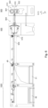
- a processing machine 01 is preferably designed as a printing machine 01 and/or as a forming machine 01, in particular a punching machine 01, more preferably as Rotary die-cutting machine.
- the printing press 01 is preferably designed as a flexographic printing press 01.
- the processing machine 01 is preferably referred to as a printing machine 01 if it has at least one application unit 614, preferably designed as a printing unit 614, and/or at least one printing unit 600, in particular regardless of whether it has further units for processing substrate 02.
- a processing machine 01 designed as a printing machine 01 additionally has at least one further such unit 900, for example at least one shaping unit 900, which is preferably designed as a punching unit 900, more preferably as a punching device 900.
- the processing machine 01 is preferably referred to as a shaping machine 01 if it has at least one shaping unit 914 and/or at least one shaping unit 900, in particular regardless of whether it has further units 600 for processing substrate 02.
- the processing machine 01 is preferably referred to as a punching machine 01 if it has at least one punching unit 914 designed as a shaping unit 914 and/or at least one punching unit 900 and/or at least one punching device 900, in particular regardless of whether it has further units 600 for processing substrate 02.
- a processing machine 01 designed as a shaping machine 01 or punching machine 01 additionally has at least one further unit 600 for processing substrate 02, for example at least one printing unit 600 and/or at least one printing unit 614.
- the processing machine 01 preferably has at least two processing units 600; 900, which preferably perform different processing processes.
- the processing of a substrate 02 describes in the foregoing and in the following preferably the changing of at least one property of the substrate 02 in question with regard to its physical properties and/or material properties, in particular its mass and/or shape and/or appearance.
- the substrate 02 can be converted into at least one further processable intermediate product and/or end product.
- the at least one processing unit 600; 900 preferably the at least one application unit 600 and/or the at least one shaping unit 900, more preferably each processing unit 600; 900, in particular an application unit 600 and/or a processing unit 600; 900 following an application unit 600, has at least one drive for the axial adjustment of the at least one forme cylinder 616; 901 of the processing unit 600; 900.
- the at least one drive for the axial adjustment of the at least one forme cylinder 616; 901 of the processing unit 600; 900 is preferably designed to axially adjust the forme cylinder 616; 901 of the processing unit 600; 900.
- the forme cylinder 616; 901 of the at least one processing unit 616; 900 is axially adjusted by means of the at least one drive for axially adjusting the forme cylinder 616; 901.
- the at least one processing unit 600; 900 preferably the at least one application unit 600 and/or the at least one shaping unit 900, more preferably each processing unit 600; 900, in particular an application unit 600 and/or a processing unit 600; 900 following an application unit 600, has at least one drive in the circumferential direction of the at least one forme cylinder 616; 901 of the processing unit 600; 900.
- the at least one drive in the circumferential direction of the at least one forme cylinder 616; 901 of the processing unit 600; 900 is preferably designed to accelerate and/or decelerate the forme cylinder 616; 901 of the processing unit 600; 900 in the circumferential direction and/or is preferably designed to adapt a processing length of the processing unit 600; 900 by accelerating and/or decelerating the forme cylinder 616; 901 in the circumferential direction.
- the at least a drive in the circumferential direction of the at least one forme cylinder 616; 901 of the processing unit 600; 900 each adjusts the forme cylinder 616; 901 of the processing unit 600; 900 in the circumferential direction.
- the at least one drive in the circumferential direction of the at least one forme cylinder 616; 901 of the processing unit 600; 900 each adjusts a processing length of the processing unit 600; 900 by accelerating and/or decelerating the forme cylinder 616; 901 in the circumferential direction.
- the at least one drive of the forme cylinder 616; 901, preferably at least the axial adjustment and/or the speed in the circumferential direction is controlled by at least one inspection device 726; 728; 916, preferably by the register control system 728 and/or the punch control system 916.
- the processing machine 01 in particular a sheet processing machine 01, preferably comprises a unit 100 designed as a feeder 100, preferably as a sheet feeder 100, and/or at least one printing unit 614 designed as an application unit 614 for applying at least one print image to substrate 02. If the processing machine 01 has at least one printing unit 614 and/or at least one printing unit 600 on the one hand and at least one shaping unit 914 and/or at least one shaping unit 900 on the other hand, it is accordingly designed both as a printing machine 01 and as a shaping machine 01.
- the processing machine 01 has at least one printing unit 614 and/or at least one printing unit 600 on the one hand and at least one punching unit 914 and/or at least one punching unit 900 and/or at least one punching device 900 on the other hand, it is accordingly designed both as a printing machine 01 and as a shaping machine 01, in particular a punching machine 01.
- the processing machine 01 is preferably designed as a sheet processing machine 01, i.e. as a processing machine 01 for processing sheet-shaped substrate 02 or sheets 02, in particular sheet-shaped printing material 02.
- the sheet processing machine 01 is designed as a sheet-fed printing press 01 and/or as a sheet-forming machine 01 and/or as a sheet-punching machine 01.
- the processing machine 01 is further preferably designed as a corrugated board sheet processing machine 01, i.e. as a processing machine 01 for processing sheet-shaped substrate 02 or sheets 02 made of corrugated board 02, in particular sheet-shaped printing material 02 made of corrugated board 02.
- the processing machine 01 is designed as a sheet-fed printing press 01, in particular as a corrugated board sheet printing machine 01, i.e. as a printing press 01 for coating and/or printing sheet-shaped substrate 02 or sheets 02 made of corrugated board 02, in particular sheet-shaped printing material 02 made of corrugated board 02.
- the printing press 01 is designed as a printing press 01 operating according to a printing form-bound printing process.
- the processing machine 01 is designed to process substrate 02, preferably a sheet-shaped substrate 02.
- the substrate 02 preferably has at least one panel.
- a panel is preferably that region of the substrate 02 which is designed as a product of the processing machine 01, in particular as an intermediate product for producing an end product, and/or is further processed, for example, into a desired or required end product and/or is designed to be further processable.
- the desired or required end product, which is preferably produced by further processing the respective panel is preferably a folding box and/or packaging.
- the term sheet-shaped substrate 02, in particular a printing material 02, specifically sheet 02 is intended to encompass in principle any flat substrate 02 and in sections, i.e. also substrates 02 in panel or plate form, i.e.
- the thus defined sheet-shaped substrate 02 or sheet 02 is formed, for example, from paper or cardboard, i.e., as a paper or cardboard sheet, or from sheets 02, panels, or possibly plates made of plastic, cardboard, glass, or metal. More preferably, the substrate 02 is corrugated cardboard. 02, in particular corrugated cardboard sheets 02. Preferably, the at least one sheet 02 is designed as corrugated cardboard 02. The thickness of a sheet 02 is preferably understood to be a dimension orthogonal to a largest area of the sheet 02. This largest area is also referred to as the main area.
- pressure fluid is applied to the at least one main surface of the sheet 02, at least partially and/or at least on one side.
- the thickness of the sheets 02 is, for example, at least 0.1 mm (zero point one millimeter), more preferably at least 0.3 mm (zero point three millimeters), and even more preferably at least 0.5 mm (zero point five millimeters).
- significantly greater thicknesses are also common, for example at least 4 mm (four millimeters) or even 10 mm (ten millimeters) and more.
- Corrugated cardboard sheets 02 are comparatively stable and therefore not very flexible. Appropriate adaptations to the processing machine 01 therefore facilitate the processing of sheets 02 of great thickness.
- the respective, preferably at least one, sheet 02 is made of paper or cardboard. More preferably, the respective sheet 02 is made of cardboard, preferably corrugated cardboard.
- paper is a flat material consisting essentially of fibers of mostly plant origin, which is formed by dewatering a fiber suspension on a screen. This creates a fiber felt that is then dried.
- the basis weight of paper is preferably a maximum of 225 g/m2 (two hundred and twenty-five grams per square meter).
- cardboard is a flat material consisting essentially of fibers of plant origin, which is formed by dewatering a fiber suspension on one or between two screens. The fiber structure is compacted and dried.
- Cardboard is preferably made by gluing or pressing together cellulose and/or. Cardboard is preferably in the form of solid board or corrugated board 02.
- Corrugated board 02 is, in the foregoing and in the following, board made of one or more layers of a corrugated paper, which is placed on a layer or between several layers of another preferably smooth paper or cardboard.
- the basis weight of cardboard is preferably over 225 g/m2 (two hundred and twenty-five grams per square meter).
- the term cardboard refers to a paper sheet, preferably coated on one side, preferably with a basis weight of at least 150 g/m2 (one hundred and fifty grams per square meter) and a maximum of 600 g/m2 (six hundred grams per square meter).
- cardboard has a high strength relative to paper.
- the processing machine 01 has several units 100; 300; 600; 700; 900; 1000.
- a unit is preferably understood to be a group of devices that interact functionally, in particular to be able to carry out a preferably self-contained processing operation of sheets 02.
- at least two and preferably at least three and more preferably all of the units 100; 300; 600; 700; 900; 1000 are designed as modules 100; 300; 600; 700; 900; 1000 or are at least each assigned to one such module.
- a module is understood in particular to be a respective unit or a structure comprising several units, which preferably has at least one transport means and/or at least one dedicated controllable and/or adjustable drive and/or is designed as an independently functional module and/or as a machine unit or functional assembly manufactured and/or assembled separately.
- a dedicated controllable and/or adjustable drive of a unit or module is understood in particular to be a drive which serves to drive movements of components of this unit or module and/or which serves to effect a transport of substrate 02, in particular sheets 02, through this respective unit or module and/or through at least one area of action of this respective unit or module and/or which serves to directly or indirectly drive at least one component of the respective unit or module intended for contact with sheets 02.
- the dedicated controllable and/or adjustable drive of an unit or module is preferably designed to drive movements of components of this unit or module and/or designed to effect transport of substrate 02 and/or designed to directly or indirectly drive at least one component of the respective unit or module intended for contact with sheet 02.
- These drives of the units 100; 300; 600; 700; 900; 1000 of the processing machine 01 are preferably designed as position-controlled electric motors in particular.
- a main drive is preferably connected to at least two components of the processing machine 01 and/or is preferably designed to jointly drive the at least two components, which are further preferably mechanically and/or virtually coupled or synchronizable with one another.
- An individual drive is preferably designed to drive one component, preferably independently of further drives and/or components.
- An individual drive preferably at least one individual drive M E of a transport element 701 is preferably a position-controlled electric motor, for example alternatively with angle of rotation control.
- a main drive, preferably at least one main drive M of the transport unit 700 is preferably a position-controlled electric motor, for example alternatively angle-controlled.
- each unit 100; 300; 600; 700; 900; 1000 has at least one drive control and/or at least one drive regulator, which is assigned to the respective at least one drive of the respective unit 100; 300; 600; 700; 900; 1000.
- the drive controls and/or drive regulators of the individual units 100; 300; 600; 700; 900; 1000 can preferably be operated individually and independently of one another.
- the drive controls and/or drive regulators of the individual units 100; 300; 600; 700; 900; 1000 are and/or can be linked to one another and/or to a machine control system of the processing machine 01 in terms of circuitry, in particular by means of at least one BUS system, in such a way that a coordinated control and/or regulation of the drives of several or all units 100; 300; 600; 700; 900; 1000 of the processing machine 01 is and/or can be carried out.
- the individual units 100; 300; 600; 700; 900; 1000 and/or in particular modules 100; 300; 600; 700; 900; 1000 of the processing machine 01 are therefore preferably electronically coordinated and/or operated, at least with regard to their drives, in particular by means of at least one virtual and/or electronic master axis.
- the virtual and/or electronic master axis is preferably specified, for example by a higher-level machine control of the processing machine 01.
- the individual units 100; 300; 600; 700; 900; 1000 of the processing machine 01 are and/or can be synchronized with one another, for example mechanically, at least with regard to their drives.
- the individual units 100; 300; 600; 700; 900; 1000 of the processing machine 01 are preferably mechanically decoupled from one another, at least with regard to their drives.
- the spatial area provided for the transport of substrate 02, which the substrate 02 occupies at least temporarily when present, is the transport path.
- the transport path is defined by at least one device for guiding the substrate 02 in an operating state of the processing machine 01.
- the units 100; 300; 600; 700; 900; 1000 of the processing machine 01 are preferably each characterized in that the section of a transport path provided for transporting sheets 02 defined by the respective unit 100; 300; 600; 700; 900; 1000 is at least substantially flat and more preferably completely flat.
- a substantially flat section of the transport path provided for the transport of sheets 02 is understood to be a section that has a minimum radius of curvature of at least two meters, more preferably at least five meters, even more preferably at least ten meters, and even more preferably at least fifty meters.
- a completely flat section has an infinitely large radius of curvature and is thus also substantially flat and thus also has a minimum radius of curvature of at least two meters.
- the units 100; 300; 600; 700; 900; 1000 of the processing machine 01 are preferably each characterized in that the transport path provided by the respective unit 100; 300; 600; 700; 900; 1000 defined section of the transport path provided for the transport of sheets 02 runs at least substantially horizontally and more preferably exclusively horizontally.
- This transport path preferably extends in a direction T, in particular transport direction T.
- a substantially horizontally running transport path provided for the transport of sheets 02 means in particular that the provided transport path, over the entire area of the respective unit 100; 300; 600; 700; 900; 1000, has exclusively one or more directions that deviate from at least one horizontal direction by a maximum of 30° (thirty degrees), preferably a maximum of 15° (fifteen degrees), and more preferably a maximum of 5° (five degrees).
- the transport path provided for the transport of sheets 02 preferably begins at a point where the sheets 02 are removed from a feeder stack 104.
- the direction T of the transport path is in particular the direction T in which the sheets 02 are transported at the point at which the direction T is measured.
- the transport direction T provided in particular for transporting sheets 02 is preferably the direction T which is preferably at least substantially and more preferably completely horizontally oriented and/or which preferably leads from a first unit 100; 300; 600; 700; 900; 1000 of the processing machine 01 to a last unit 100; 300; 600; 700; 900; 1000 of the processing machine 01, in particular from a sheet feeder unit 100 or a substrate feed device 100 on the one hand to a delivery unit 1000 or a substrate discharge device 1000 on the other hand, and/or which preferably points in a direction in which the sheets 02 are transported apart from vertical movements or vertical components of movements, in particular from a first contact with a unit 300; 600; 700; 900; 1000 of the processing machine 01 arranged downstream of the substrate feed device 100 or first contact with the processing machine 01 to a last contact with the processing machine 01.
- the feed device 300 is an
- a direction A is preferably a direction A oriented orthogonal to the transport direction T of the sheets 02 and/or orthogonal to the intended transport path of the sheets 02 through the at least one application unit 600 and/or through the at least one shaping unit 900 and/or through the at least one sheet delivery 1000.
- the transverse direction A is preferably a horizontally oriented direction A.
- a longitudinal axis of the at least one forme cylinder 616 is oriented parallel to the transverse direction A.
- the transverse direction A is an axial direction.
- a working width of the processing machine 01 and/or of the at least one application unit 600 and/or of the at least one shaping unit 900 and/or of the at least one sheet delivery 1000 is preferably a dimension that preferably extends orthogonally to the intended transport path of the sheets 02 through the at least one application unit 600 and/or the at least one shaping unit 900 and/or the at least one sheet delivery 1000, more preferably in the transverse direction A.
- the working width of the processing machine 01 preferably corresponds to a maximum width that a sheet 02 may have in order to still be able to be processed with the processing machine 01, i.e. in particular a maximum sheet width that can be processed with the processing machine 01.
- the width of a sheet 02 is to be understood in particular as its dimension in the transverse direction A.
- the working width of the processing machine 01 preferably corresponds to the working width of the at least one application unit 600 and/or the at least one Shaping unit 900 and/or the at least one sheet delivery 1000.
- the working width of the processing machine 01 is preferably at least 100 cm (one hundred centimeters), more preferably at least 150 cm (one hundred and fifty centimeters), even more preferably at least 160 cm (one hundred and sixty centimeters), even more preferably at least 200 cm (two hundred centimeters) and even more preferably at least 250 cm (two hundred and fifty centimeters).
- a vertical direction V preferably denotes a direction that is preferably directed vertically upwards from a floor.
- the vertical direction V is preferably arranged parallel to the normal vector of a plane spanned by the transport direction T and the transverse direction A.
- Components preferably have their height in the vertical direction V.
- the vertical direction V is preferably oriented such that it points from the printing substrate 02 arranged in a processing station 910 towards a forme cylinder 901 of the shaping device 900.
- a direction X preferably denotes the direction along the lateral extent of the substrate 02.
- the direction X is oriented parallel to the transverse direction A, i.e., an axial direction, for a substrate 02 arranged in the processing machine 01.
- the direction X points from a first side edge of the substrate 02 to a second side edge of the substrate 02 opposite the first side edge.
- a direction Y preferably denotes the direction along the longitudinal extent of the substrate 02.
- the direction Y is preferably oriented parallel to the transport direction T, i.e., preferably points in the direction of the transport path, for a substrate 02 arranged in the processing machine 01.
- the direction Y points from a rear edge 04 of the substrate 02 to its front edge 03.
- the front edge 03 is preferably the edge 03 of the substrate 02 which is along the transport path in the processing machine 01. as the first edge of the substrate 02 comes into contact with the respective aggregates 100; 300; 600; 700; 900; 1000, in particular with the processing points 621; 910.
- the processing machine 01 preferably has at least one substrate feed device 100, which is more preferably designed as an assembly 100, in particular a substrate feed assembly 100 and/or as a module 100, in particular a substrate feed module 100.
- the at least one substrate feed device 100 is preferably designed as a sheet feeder 100 and/or a sheet feeder assembly 100 and/or a sheet feeder module 100.
- the at least one substrate feed device 100 is preferably the first assembly 100 of the processing machine 01, in particular in the transport direction T.
- the substrate feed device 100 is preferably designed to feed substrate 02, preferably sheets 02, to subsequent processing assemblies 600; 900.
- the substrate feed device 100 preferably separates the substrates 02 so that the substrates 02 are transported through the processing machine 01 one after the other, preferably at a distance from one another.
- the at least one substrate feed device 100 preferably has at least one acceleration means, preferably at least one primary acceleration means and/or at least one secondary acceleration means, for accelerating the substrate 02 to the processing speed.
- the at least one substrate feed device 100 preferably has at least one front stop and/or at least one lateral stop and/or at least one rear stop, which preferably aligns the at least one substrate 02. For example, at least one stop is fixed or movable, toward the substrate 02 and/or away from the substrate 02.
- the at least one substrate 02 is aligned in the at least one substrate feed device 100 by means of the at least one fixed or movable stop.
- the processing machine 01 has, for example, at least one unit designed as a conditioning device, in particular a conditioning unit, which is more preferably designed as a module, in particular as a conditioning module.
- a conditioning device is For example, it is designed as a preparation device, in particular as a preparation device for applying primer, or as a post-treatment device, in particular as a post-treatment device for applying paint.
- the processing machine 01 preferably has at least one unit designed as a preparation device, in particular a preparation unit, which is further preferably designed as a module, in particular as a preparation module, and represents a conditioning device.
- the processing machine 01 preferably has at least one post-treatment device.
- the processing machine 01 preferably has at least one unit 300, preferably a feed device 300, which is more preferably designed as a feed unit 300 and/or feed module 300.
- the at least one feed device 300 is alternatively designed as a component of the substrate feed device 100 or another unit.
- the substrate feed device 100 preferably comprises the feed unit 300.
- the feed unit 300 preferably has the at least one feeder stack 104.
- the feeder stack 104 preferably comprises a plurality of sheets 02, which are preferably stacked at least temporarily in a storage area 166.
- the processing machine 01 has, for example, at least one, preferably at least two, more preferably at least four, more preferably at least six, for example eight, units 600, e.g. the application unit 600, which is preferably designed as a module 600, in particular an application module 600.
- the at least one application unit 600 is preferably arranged and/or constructed depending on the function and/or application method.
- the at least one application unit 600 preferably serves to apply at least one respective application fluid or coating agent over the entire surface and/or at least part of the surface to the sheets 02.
- An example of an application unit 600 is a printing unit 600 or printing module 600, which serves in particular to apply printing ink and/or ink to substrate 02, in particular sheet 02.
- the at least one application unit 600 is designed to apply application fluid, preferably printing ink and/or ink, for example over the entire surface and/or part of the surface of the sheets 02.
- any priming unit and/or any coating unit that may be arranged are also considered to be such an application unit 600 or printing unit 600.
- the at least one application unit 600 preferably has the at least one applicator 614.
- at least a first application unit 600 in the transport direction T is designed as a priming unit.
- at least a last application unit 600 in the transport direction T is designed as a coating unit.
- at least one, preferably at least four, application units 600, which are preferably arranged downstream of the priming unit and/or upstream of the coating unit, are designed as printing units 600.
- application units 600 can preferably be differentiated with regard to their application methods.
- An example of an application unit 600 is a form-based application unit 600, which in particular has at least one fixed, physical and preferably replaceable printing form for the application of printing fluid.
- Form-based application units 600 preferably operate according to a planographic printing process, in particular an offset planographic printing process and/or a gravure printing process and/or a letterpress printing process, particularly preferably a flexographic printing process.
- the corresponding application unit 600 is preferably a flexographic application unit 600 or flexographic printing unit 600, in particular a flexographic application module 600 or flexographic printing module 600.
- the at least one application unit 600 is designed as an offset printing unit 600.
- a preferred embodiment of the application unit 614 is intended to provide substrate 02, in particular sheet 02 and/or printing material 02, with application fluid from below, for example, to print it.
- the forme cylinder 616 preferably arranged below the impression cylinder 617.
- the sheets 02 are printed from above.
- the printing unit 600 is then preferably configured in a mirror-inverted sequence with structural adjustments.
- the sheets 02 are punched on the opposite side to the printed image. Therefore, printing from below is the preferred embodiment.
- the at least one application unit 600 preferably each application unit 600, preferably has at least one drive.
- the at least one application unit 600 preferably each application unit 600, preferably has at least one drive in the circumferential direction of the at least one forme cylinder 616 of the processing unit 600.
- the at least one drive in the circumferential direction of the at least one forme cylinder 616 of the processing unit 600, preferably of the forme cylinder 616 of the application unit 600, is preferably designed to accelerate and/or decelerate the forme cylinder 616 of the processing unit 600, preferably the forme cylinder 616 of the application unit 600, in the circumferential direction.
- the at least one drive in the circumferential direction of the at least one forme cylinder 616 of the processing unit 600 is preferably designed to adapt a processing length of the processing unit 600, preferably a processing length of the forme cylinder 616, by accelerating and/or decelerating the forme cylinder 616 in the circumferential direction.
- the at least one drive in the circumferential direction of the at least one forme cylinder 616 of the processing unit 600 preferably accelerates and/or decelerates the forme cylinder 616 of the processing unit 600 in the circumferential direction.
- the at least one drive in the circumferential direction of the at least one forme cylinder 616 of the processing unit 600 adapts a processing length of the processing unit 600 by accelerating and/or decelerating the forme cylinder 616 in the circumferential direction.
- the at least one forme cylinder 616 is driven in the circumferential direction by means of the at least one drive, preferably a single drive accelerated and/or decelerated.
- the at least one forme cylinder 616 has at least one drive, preferably an individual drive, more preferably a position-controlled electric motor, for the axial adjustment of the forme cylinder 616.
- the at least one processing unit 600 preferably designed as an application unit 600, preferably has at least one drive for the axial adjustment of the at least one forme cylinder 616 of the processing unit 600.
- the at least one drive for the axial adjustment of the at least one forme cylinder 616 of the processing unit 600 is preferably designed to adjust the forme cylinder 616 of the processing unit 600 axially, preferably in the transverse direction A.
- the at least one forme cylinder 616 is axially adjustable.
- the at least one forme cylinder 616 of the at least one application unit 600 is axially adjusted by means of the at least one drive for the axial adjustment of the forme cylinder 616.
- the axial adjustment occurs at least during the setup of the processing machine 01 for a new processing job.
- the axial adjustment occurs additionally or alternatively during the processing of substrate 02.
- the axial adjustment is controlled manually by an operator.
- the at least one drive of the forme cylinder 616 preferably at least the axial adjustment, is controlled by the at least one inspection device 726; 728; 916, preferably by the register control system 728.
- the processing machine 01 has, for example, at least one unit designed as a drying device, in particular a drying unit, which is further preferably designed as a module, in particular as a drying module.
- at least one drying device 506 and/or at least one post-drying device is a component of at least one unit 100; 300; 600; 700; 900; 1000, preferably designed as a module 100; 300; 600; 700; 900; 1000.
- at least one application unit 600 has at least one drying device 506 and/or has at least one Transport device 700 and/or at least one unit 700 designed as a transport unit 700.
- the processing machine 01 has at least one transport device 700, which is designed as an assembly 700, in particular the transport assembly 700, and/or as a module 700, in particular as a transport module 700.
- the transport device 700 is also referred to as transport means 700. Additionally or alternatively, the processing machine 01 preferably has transport devices 700, for example as components of other assemblies and/or modules.
- the at least one transport device 700 has at least one drive, preferably a single drive.
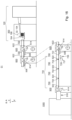
- the at least one transport assembly 700 has the at least one transport element 701.
- the at least one transport assembly 700 has a plurality of transport elements 701, which are arranged one behind the other in the transport direction T.
- the transport unit 700 has at least one individual drive M E for an axial adjustment of at least one transport element 701, and/or at least one main drive M, for example at least one main drive M for driving in the circumferential direction, preferably for rotating, in particular rotary, driving, at least one transport element 701.
- the processing machine 01 preferably has at least one shaping device 900, which is more preferably designed as an assembly 900, in particular a shaping assembly 900 or a punching assembly 900, and/or as a module 900, in particular as a shaping module 900 or a punching module 900 and/or as a punching device 900.
- a shaping assembly 900 is preferably an embodiment of a processing assembly 900.
- the processing machine 01 preferably has at least one shaping assembly 900 designed as a punching assembly 900.
- the at least one shaping device 900 is preferably designed as a rotary punching device 900 and/or preferably has at least one shaping unit 914 or punching unit 914. more preferably a rotary punching unit.
- a shaping device 900 should also be understood to mean an embossing device and/or a creasing device.
- a perforating device is preferably also a form of a punching device 900.
- the at least one substrate 02, in particular sheet 02 is punched and/or creasing and/or embossed and/or perforated in the at least one preferably subsequent processing unit 900, preferably designed as a shaping unit 900.
- the at least one punching unit 900 preferably has the at least one shaping unit 914, preferably designed as a punching unit 914.
- the shaping unit 914 designed as a punching unit 914 has at least one forme cylinder 901, preferably designed as a punching cylinder 901.
- the forme cylinder 901 of the shaping unit 900 has at least one drive assigned to it, preferably a single drive, more preferably a position-controlled electric motor.
- the at least one shaping unit 900 preferably the processing unit 900 following an application unit 600, preferably has at least one drive in the circumferential direction of the at least one forme cylinder 901 of the processing unit 900.
- the at least one drive in the circumferential direction of the at least one forme cylinder 616; 901 of the processing unit 600; 900, preferably of the forme cylinder 901 of the punching unit 900, is preferably designed to accelerate and/or decelerate the forme cylinder 616; 901 of the processing unit 600; 900, preferably the forme cylinder 901 of the punching unit 900, in the circumferential direction.
- the at least one drive accelerates and/or decelerates the forme cylinder 901 of the processing unit in the circumferential direction of the at least one forme cylinder 901 of the processing unit 900. 900 in the circumferential direction.
- the at least one drive in the circumferential direction of the at least one forme cylinder 901 of the processing unit 900 adjusts a respective processing length of the processing unit 900 by accelerating and/or decelerating the forme cylinder 901 in the circumferential direction.
- the at least one forme cylinder 901 can be accelerated and/or decelerated in the circumferential direction by means of the at least one drive, preferably a single drive.
- the at least one forme cylinder 901 preferably has at least one drive, preferably a single drive, more preferably a position-controlled electric motor, for the axial adjustment of the forme cylinder 901.
- the at least one processing unit 900 preferably the following one, preferably designed as a punching unit 900, preferably has at least one drive for the axial adjustment of the at least one forme cylinder 901 of the processing unit 900.
- the at least one drive for the axial adjustment of the at least one forme cylinder 901 of the processing unit 900 is preferably designed to adjust the forme cylinder 901 of the processing unit 900 axially, preferably in the transverse direction A.
- the at least one forme cylinder 901 is preferably axially adjustable.
- the at least one forme cylinder 901 of the at least one shaping unit 900 is preferably axially adjusted by means of the at least one drive for the axial adjustment of the forme cylinder 901.
- the axial adjustment occurs at least during the setup of the processing machine 01 for a new processing job.
- the axial adjustment occurs additionally or alternatively during the processing of substrate 02.
- the axial adjustment is controlled manually by an operator.
- the axial adjustment is controlled by the at least one inspection device 726; 728; 916, preferably by the punching control system 916.
- the at least one shaping unit 900 preferably the at least one subsequent processing unit 900, preferably has at least one drive at least one counter-punching cylinder 902 of the processing unit 900.
- the at least one drive of the counter-punching cylinder 902 of the processing unit 900 is preferably designed to adapt a processing length of the processing unit 900 by accelerating and/or decelerating the counter-punching cylinder 902 in the circumferential direction.
- the at least one drive of the counter-punching cylinder 902 of the processing unit 900 preferably adapts a processing length of the processing unit 900 by accelerating and/or decelerating the counter-punching cylinder 902 in the circumferential direction.
- the at least one forme cylinder 901 of the shaping device 900 is arranged in the vertical direction V above the at least one counter-punching cylinder 902.
- gravity is used in the processing method to assist in the application of force.
- the sheet processing machine 01 is preferably characterized in that, along the transport path provided for the transport of sheets 02, after the at least one shaping station 910, at least one separation device 903 for removing at least one waste piece from at least one sheet 02 is arranged.
- the separation device 903 is preferably designed for the complete removal of waste pieces from the respective sheet 02.
- the at least one separation device 903 is therefore particularly useful for separating the remaining pieces, in particular the former parts of the sheet 02 that have already been completely or partially severed from the sheet 02 and are to be removed from the sheet 02, in particular those parts of the sheet 02 that are to continue to be treated as sheet 02 and, if necessary, further processed.
- the at least one separation device 903 is designed, for example, as a separation unit 903 and/or as a separation module 903.
- the at least one separation device 903 is a component of another unit 900 or module 900, in particular of the at least one shaping unit 900 or shaping module 900.
- the at least one separation device 903 preferably has at least one transport means 904 designed as a separation transport means 904, in particular for transporting sheets 02.
- the at least one separation transport means 904 preferably serves to transport respective sheets 02 along the transport path provided for the transport of sheets 02 and/or in the transport direction T, while waste pieces are removed from the respective sheets 02.
- the waste pieces are preferably transported in a respective direction that has at least one component that is oriented orthogonal to the transport direction T, preferably counter to a vertical direction V, for example vertically downwards.
- at least the force of gravity is also used to remove such waste pieces from the respective sheet 02.
- the processing machine 01 preferably has at least one unit 1000 designed as a substrate delivery device 1000, in particular a delivery 1000, in particular a sheet delivery 1000, in particular a delivery unit 1000, which is further preferably designed as a module 1000, in particular as a delivery module 1000.
- the at least one substrate delivery device 1000 is preferably arranged downstream of the at least one shaping unit 900, further preferably downstream of the at least one separation device 903, further preferably following the at least one transport means 906.
- the substrate delivery device 1000 preferably comprises at least one delivery stack support 48 and at least one diverting delivery device 51.
- the substrate delivery device 1000 designed as a delivery device 1000 preferably has at least one preferably adjustable and/or controllable sheet diverter 49, which is designed to guide sheets 02 either to the delivery stack support 48 or to the diverting delivery device 51.
- the products are deposited on the at least one delivery stack support 48.
- at least one sample sheet and/or sheet containing waste is deposited in the at least one diverter 51.
- the at least one sheet diverter 49 controls the transport path so that the processed sheet 02 is deposited either on the delivery stack support 48 or in the diverter 51.
- the processing machine 01 has, for example, at least one unit designed as a further processing device, in particular a further processing unit, which is more preferably designed as a module, in particular as a further processing module.
- the further processing unit is preferably arranged downstream of the at least one shaping device 900 in the transport direction T.
- the further processing unit is arranged downstream of the at least one sheet delivery device 1000 in the transport direction T.
- the at least one further processing device is designed as a gluing device and/or folding device.
- the processing machine 01 preferably has transport means 700; 904; 906 at one or more locations.
- the at least one transport unit 700 is a transport means 700.
- the at least one transport means 700; 904; 906 is preferably designed to move substrate 02, preferably sheets 02, more preferably individual sheets 02, preferably along the transport path through the processing machine 01.
- at least one transport means 700, preferably at least one suction transport means 700, is arranged at least between two successive processing units 600; 900.
- the at least one transport means 700; 904; 906 has at least one transport element 701.
- the at least one transport unit 700 designed as a transport means 700 has at least one, preferably at least two, more preferably at least three, more preferably at least four, more preferably at least five transport elements 701.
- the at least one transport unit 700 configured as a transport means 700 has a maximum of twenty, preferably a maximum of twelve, more preferably a maximum of eleven, transport elements 701.
- the at least one transport element 701 is in contact with the substrate 02, at least in the presence of the substrate 02.
- the at least one transport element 701 is configured to move the substrate 02.
- At least one of these transport means 700; 906 is preferably designed as a suction transport means 700; 906, in particular as a suction belt and/or as a suction box belt and/or as a roller suction system and/or as a suction roller.
- the at least one transport unit 700 is preferably designed as a suction transport means 700.
- Such suction transport means 700; 906 preferably serve to move substrate 02 forward in a controlled manner and/or to enable movements while the substrate 02 is held against at least one counter-pressure surface of the corresponding suction transport means 700; 906.
- a relative negative pressure is preferably used to pull and/or push the substrate 02, preferably the sheet 02, against at least one transport surface 702.
- a transport movement of the substrates 02 is preferably generated by a corresponding, in particular circumferential, movement of the at least one transport surface 702.
- the substrate 02 is transported by the at least one suction transport means 700; 906 is held in its path, for example, along the transport path provided for the transport of substrate 02, and in doing so, a transport movement of the substrate 02 is generated by a force predetermined by another, for example upstream and/or downstream, transport means 700; 904; 906.
- the negative pressure is in particular a negative pressure relative to an ambient pressure, in particular relative to an atmospheric pressure.
- the suction transport means 700; 906 is therefore preferably understood to be a device which has at least one counterpressure surface, which is more preferably designed as a sliding surface and/or as a particularly movable transport surface 702 and which is, for example, at least partially movable at least in the transport direction T.
- the respective suction transport means 700; 906 preferably has at least one vacuum chamber, which is more preferably connected to at least one vacuum source via a suction line.
- the vacuum source comprises, for example, a fan.
- the at least one vacuum chamber has at least one suction opening 703, which serves to suck in the substrate 02.
- the substrates 02 are sucked into a position that closes the at least one suction opening 703 or are only sucked against a transport surface 702 in such a way that ambient air can still pass past the substrate 02 into the suction opening 703.
- the transport surface 702 has one or more suction openings.
- the suction openings preferably serve to transmit a vacuum from the suction opening 703 of the vacuum chamber to the transport surface 702, in particular without pressure losses or with very low pressure losses.
- the suction opening 703 acts on the substrate 02 to be transported in such a way that it is sucked against the transport surface 702, preferably without the transport surface 702 having suction openings.
- at least one deflection means is arranged, which directly or indirectly ensures a circumferential movement of the at least one transport surface 702.
- the at least one deflection means and/or the transport surface 702 itself is driven and/or drivable, in particular to ensure a movement of the substrate 02 in the transport direction T.
- the transport surface 702 allows the substrate 02 to slide along the transport surface 702.
- a first embodiment of a suction transport means 700; 906 is a suction belt.
- a suction belt is understood to be a device that has at least one flexible conveyor belt, the surface of which serves as a transport surface 702.
- the at least one conveyor belt is preferably deflected by deflection means designed as deflection rollers and/or deflection rolls and/or is preferably self-contained, in particular such that an endless circulation is possible.
- the at least one The conveyor belt preferably has a plurality of suction openings.
- the at least one conveyor belt preferably covers the at least one suction opening 703 of the at least one vacuum chamber in at least a portion of its circulating path.
- the vacuum chamber is then connected to the environment and/or to the substrate 02 only through the suction openings of the at least one conveyor belt.
- Support means are preferably provided which prevent the at least one conveyor belt from being pulled too far into the vacuum chamber or at all and/or which ensure that the transport surface 702 assumes a desired shape, for example such that it forms a flat surface at least in the region in which its suction openings are connected to the vacuum chamber.
- a circumferential movement of the at least one conveyor belt then results in a forward movement of the transport surface 702, wherein the substrate 02 is held securely on the transport surface 702 precisely in the region in which it lies opposite the suction opening 703 covered by the at least one conveyor belt with the exception of the suction openings.
- a second, preferred embodiment of the transport means 700; 906, preferably a suction transport means 700; 906, is a roller suction system.
- a roller suction system is understood to be a device in which the at least one transport surface 702 is formed from at least sections of the lateral surfaces of a plurality of transport elements 701, preferably a plurality of transport rollers and/or transport cylinders.
- the transport elements 701, in particular the transport rollers and/or transport cylinders thus each form, for example, closed and/or rotating parts of the transport surface 702.
- the roller suction system preferably has a plurality of suction openings 703. These suction openings 703 are preferably arranged at least between adjacent transport elements 701, in particular transport rollers and/or transport cylinders.
- At least one cover mask is arranged, which preferably represents a boundary of the vacuum chamber.
- the cover mask preferably has the plurality of suction openings 703.
- the cover mask preferably forms a substantially flat surface.
- the transport elements 701, in particular the transport rollers and/or transport cylinders, are preferably arranged such that they are intersected by this flat surface and more preferably protrude only slightly, for example only a few millimeters, beyond this flat surface, in particular in a direction facing away from the vacuum chamber.
- the suction openings 703 are then preferably frame-shaped and each surround at least one of the transport rollers and/or transport cylinders.
- a rotating movement in the circumferential direction preferably describes a circumferential, preferably rotary, movement.
- a circumferential, preferably rotary, movement of the transport rollers and/or transport cylinders then results in a forward movement of the corresponding parts of the transport surface 702.
- Substrate 02 preferably sheet 02
- the drive forces from the at least one transport element 701 are preferably transmitted to the substrate 02 in a frictionally engaged manner.
- the transport unit 700 is designed as at least one suction transport means 700 with the at least one roller suction system.
- a suction transport means 700 comprises at least two roller suction systems, which are preferably each designed as an individually driven roller suction system.
- the roller suction system is preferably also referred to as a suction box.
- the movement of the at least one transport element 701 in the circumferential direction or in the transport direction T preferably describes a movement of a point on the lateral surface of the transport element 701 about its axis of rotation, wherein a substrate 02 is preferably moved in the transport direction T by this movement if the substrate 02 is present.
- a third embodiment of a suction transport means 700; 906 is a suction box belt.
- a suction box belt is understood to be a device that has a plurality of of suction boxes which are in particular movable in a rotating manner and which each have an outer surface serving as a transport surface 702.
- a fourth embodiment of a suction transport means 700; 906 is at least one suction roller.
- a suction roller is understood to be a roller whose outer surface serves as a transport surface 702 and has a plurality of suction openings, and which has at least one vacuum chamber within its interior, which is connected, for example, to at least one vacuum source via a suction line.
- a fifth embodiment of a suction transport means 700; 906 is at least one sliding suction device.
- the sliding suction device is preferably designed as a passive transport means and serves in particular to specify boundary conditions regarding a position of a respective substrate 02 without setting the substrate 02 itself in motion.
- the respective sliding suction device preferably has at least one sliding surface and at least one vacuum chamber and at least one suction opening. This at least one sliding surface then serves as a counterpressure surface and serves as the transport surface 702.
- the transport surface 702 designed as a sliding surface is preferably not moved.
- the sliding surface serves as a counterpressure surface against which the corresponding substrates 02 are pressed.
- the substrates 02 can nevertheless be moved along the sliding surface, in particular if they are otherwise subjected to a force oriented at least parallel to the sliding surface.
- a sliding suction device can be used to bridge an area between two driven suction transport means 700; 906.
- suction transport means 700; 906 can, for example, have at least one common vacuum source and/or at least one common vacuum chamber and/or at least one and/or cooperate as a suction transport means 700; 906 and/or be arranged one behind the other and/or next to each other. Such combinations are then preferred. each to be assigned to at least two of the embodiments of suction transport means 700; 906.
- a section of the transport path provided for the transport of substrate 02, which is defined by the transport unit 700, preferably the respective suction transport means 700; 906, is located below the preferably movable transport surface 702 of the transport unit 700.
- the transport surface 702 preferably serves as a counterpressure surface and is, for example, at least partially movable at least in the transport direction T.
- the suction openings 703 or intake openings of the suction transport means 700; 906, at least during their connection to the at least one vacuum chamber, preferably point at least also or only downwards and/or its suction effect is preferably directed at least also or only upwards.
- the substrates 02 are then transported by the suction transport means 700; 906, preferably in a suspended state.
- a section of the transport path provided for the transport of substrate 02 which section is defined by the transport unit 700, preferably the respective suction transport means 700; 906, is located above the particularly movable transport surface 702.
- the transport surface 702 preferably serves as a counter-pressure surface and is, for example, at least partially movable at least in the transport direction T.
- the substrates 02 are then transported by the suction transport means 700; 906 preferably transported lying down.
- At least one transport unit 700 of the processing machine 01 is arranged upstream of at least one subsequent processing unit 600; 900 of the processing machine 01.
- at least one transport unit 700 is preferably arranged upstream of a processing unit 600; 900, preferably at least the at least one application unit 600 and/or the at least one shaping unit 900.
- At least one processing unit 600; 900 is preferably arranged downstream of a first transport unit 700 in the transport direction T.
- at least one transport unit 700 is arranged upstream of the first processing unit 600; 900 in the transport direction T, in particular a first application unit 600.
- the at least one application unit 600 with the at least one application unit 614 designed as a printing unit 614 is preferably arranged downstream of the first transport unit 700.
- the at least one application unit 600 is preferably designed to apply at least one printed image to the substrate 02.
- the at least one printed image is preferably visible, for example in color.
- at least one application unit 600 transfers at least one colorless printed image, for example a varnish application, to the at least one substrate 02.
- the at least one application unit 600 preferably has the at least one printing unit 614 with the forme cylinder 616.
- the forme cylinder 616 preferably has a drive associated with it, preferably at least one individual drive, preferably at least one position-controlled electric motor.
- the at least one application unit 600 preferably has at least one drive for the axial adjustment of the at least one forme cylinder 616 of the at least one application unit 600 and/or at least one drive in the circumferential direction of the at least one forme cylinder 616 of the at least one application unit 600.
- the at least one application unit 600 is preferably designed as a flexographic application unit 600 or as an offset printing unit 600.
- the processing machine 01 has at least four application units 600, in particular flexographic application units 600.
- the processing machine 01 comprises at least six, for example eight and/or a maximum of ten, application units 600, wherein the individual application units 600 preferably differ at least partially in the printing fluid processed by them and/or a print image element applied by them to the printing substrate 02.
- At least one transport means 700 is arranged between each two application units 600.
- at least one transport unit 700 is preferably arranged between each two successive processing units 600; 900.
- the at least one printing unit 614 is preferably designed as a flexographic printing unit, which is designed in particular according to the principle of the flexographic printing process for applying printing fluid to the sheet 02.
- the applicator unit 614 comprises at least one forme cylinder 616, at least one impression cylinder 617, more preferably additionally at least one anilox roller 618, and at least one ink fountain 619.
- the ink fountain 619 preferably contains printing fluid and is configured to deliver the printing fluid to the anilox roller 618.
- the anilox roller 618 is configured to transfer the printing fluid to at least one printing forme of the forme cylinder 616 for printing a printing substrate 02.
- the forme cylinder 616 and the impression cylinder 617 define a processing point 621 of the applicator unit 614.
- a peripheral surface of the forme cylinder 616 and a peripheral surface of the impression cylinder 617 preferably define the processing point 621, designed as a printing nip 621, through which preferably sheets 02 can pass through the printing unit 614.
- the printing nip 621 is preferably the area in which the respective forme cylinder 616, on the one hand, and the respective impression cylinder 617, on the other hand, are closest to each other.
- the printing unit 614 has at least one forme cylinder 616.
- the forme cylinder 616 has at least one printing form and at least one holder 626 for the at least one printing form.
- the holder 626 of the printing form is designed, for example, as a clamping device.
- the holder 626 of the printing form is designed along a circumferential direction of the outer surface of the forme cylinder 616 as a non-printing region of the outer surface of the forme cylinder 616.
- the non-printing region of the forme cylinder 616 preferably has a length in the circumferential direction of the forme cylinder 616 which is preferably at least 3%, preferably at least 5%, more preferably at least 8%, of the circumferential length of the forme cylinder 616.
- the length of the non-printing region is preferably determined by the length in the circumferential direction of the printing region of the forme cylinder 616, in particular the length of the at least one printing form in the circumferential direction of the forme cylinder 616.
- the non-printing area corresponds to a cylinder channel of the at least one forme cylinder 616.
- the at least one impression cylinder 617 has at least one holder 627.
- the at least one printing forme, more preferably exactly one printing forme, and the at least one non-printing region, preferably exactly one non-printing region are preferably arranged one behind the other.
- the holder 626 is preferably arranged in front of the printing area of the forme cylinder 616, more preferably a rear edge of the non-printing area of the forme cylinder 616 in the direction of rotation of the forme cylinder 616 arranged in front of the printing area of the forme cylinder 616.
- a front edge of the printing area of the forme cylinder 616 is identical to the rear edge of the non-printing area of the forme cylinder 616.
- At least one first application unit 600 in the transport direction T is designed as a priming unit and/or at least one last application unit 600 in the transport direction T is designed as a painting unit.
- the at least one processing unit 600 which is preferably designed as an application unit 600, is preferably followed by at least one preferably further processing unit 600; 900.
- a first application unit 600 is preferably followed by at least one second application unit 600, preferably at least four further application units 600.
- the at least one application unit 600 preferably the last application unit 600 of the application units 600, is preferably followed by the at least one shaping device 900, preferably the at least one punching unit 900.
- the at least one subsequent processing unit 600; 900 is thus preferably designed as an application unit 600, preferably with a flexographic printing unit, or punching unit 900, preferably with a rotary punching unit.
- the at least one shaping device 900 with the at least one shaping unit 914 is preferably arranged.
- the at least one shaping device 900 is preferably designed as a punching device 900 and/or as a rotary punching device 900.
- the at least one shaping device 900 preferably has at least one and more preferably exactly one processing station 910, which is preferably designed as a shaping station 910, which is formed by at least and more preferably exactly one processing station, in particular as
- the forming point 910 is preferably the region in which the respective forme cylinder 901 and the respective counter-pressure cylinder 902 are closest to each other.
- the at least one forming point 910 is preferably formed as at least one punching point 910.
- the punching cylinder 901 is preferably arranged in the punching position.
- the punching cylinder 901 preferably remains in its punching position or the punching cylinder 901 is transferred to a parked position, preferably in the vertical direction V.
- at least one tool of the punching cylinder 901, preferably its punching knife preferably comes into contact with the punching pad of the counter-punching cylinder 902 in the punching position.
- This position of the counter-punching cylinder 902 is referred to as the punching position or working position of the counter-punching cylinder 902.
- the punching cylinder 901 and the counter-punching cylinder 902 are arranged in the punching position.
- the counter-punching cylinder 902 preferably has at least one drive, for example at least one actuator.
- the counter-punching cylinder 902 is preferably arranged so that it can be transferred from the punching position to a parked position.
- the counter-punching cylinder 902 is adjustable on a linear guide 953 predominantly in the vertical direction V.
- the parked position is a position in which the counter-punching cylinder 902 is brought out of contact with the punching cylinder 901.
- the counter-punching cylinder 902 thus preferably remains essentially in its punching position.
- the counter-punching cylinder 902 is parked only far enough that the counter-punching cylinder 902 is out of contact.
- the actuator only parks the counter-punching cylinder 902 between 15 and 30 cm.
- the actuator has a maximum stroke of 50 cm, more preferably 30 cm.
- the punching cylinder 901 and/or the counter-punching cylinder 902 are serviced, in particular, its tool is changed when the counter-punching cylinder 902 is arranged in the parked position.
- the shaping device 900 in particular the shaping unit 914, preferably has the at least one tool; more preferably, the at least one forme cylinder 901 comprises the at least one tool.
- the tool of the shaping device 900, in particular of the shaping unit 914, preferably the tool of the forme cylinder 901 is at least temporarily in direct contact with the impression cylinder 902, in particular in the region of the shaping point 910.
- the at least one forme cylinder 901 is preferably designed as a punching cylinder 901.
- the at least one tool of the forme cylinder 901 is preferably designed as a shaping tool, in particular a punching tool.
- the at least one forme cylinder 901 designed as a punching cylinder 901 preferably has the at least one punching tool, which preferably has at least one knife, more preferably vertically arranged knives. The knives are preferably arranged discontinuously and differ depending on the punching job.
- the at least one counter-pressure cylinder 902 configured as a counter-punching cylinder 902 preferably has a cover or punching pad.
- the punching pad is preferably made of a plastic and/or rubber and has slightly elastic properties.
- the punching pad is preferably made of a plastic such as polyurethane or the like.
- the punching pad is preferably easily depressible, for example, and can partially recover.
- the at least one forme cylinder 901 has a tool length of its at least one tool with which the at least one substrate 02 is processed.
- the form length or tool length is, for example, between 450 mm and 1600 mm.
- the at least one forme cylinder 901, which is designed in particular as a punching cylinder 901, preferably has the at least one tool designed as a shaping tool, preferably as a punching tool.
- the at least one tool preferably has at least one working surface.
- the at least one shaping tool is mounted on a mounting plate.
- a forme cylinder 901 of a shaping unit 900 has a plurality of holes and/or bores to which the mounting plate and/or the shaping tool can be directly mounted and/or is preferably mounted.
- the working surface of the shaping tool is defined as a surface whose position in the radial direction runs through the outermost tool shapes.
- the shaping tool has a plurality of processing elements, preferably punching elements. Such punching elements are designed, for example, as punching blades.
- the height of the punching elements is between 10 mm and 30 mm.
- the working surface has a dimension in the circumferential direction.
- the working surface runs in the circumferential direction of the forme cylinder 901 from a tool start to a tool end.
- the tool start is defined by the start of elevations of processing elements and/or punching elements and/or tool parts, in particular punching blades, which are provided for processing a substrate 02.
- a working surface preferably amounts to between 30% and 90% of the outer surface of the forme cylinder 901. Covering here refers in particular to the projection of the working surface directly onto the outer surface in the radial direction.
- the working surface can preferably be divided into several sections with lengths in the circumferential direction.
- the working surface of the forming tool preferably has several sections with working lengths for processing consecutively arranged sections on a substrate 02. The number of sections depends on the number of processing sections of the order or the sections on a sheet 02. Accordingly, each processing length of a section is assigned a section length of the working surface.
- the at least one forme cylinder 901 preferably has an inner radius of between 175 mm and 300 mm.
- the radius in particular the radius including the punching elements, is preferably between 190 mm and 350 mm.
- the surface of the at least one tool is preferably curved.
- the at least one tool which is preferably designed as a punching tool, is preferably shell-shaped, preferably half-shell-shaped.
- the inner diameter of the at least one tool is preferably adapted to the diameter of the surface of the at least one forme cylinder 901, so that the at least one forme cylinder 901 can preferably be equipped with the at least one tool.
- at least two, for example at least three, tools are then arranged on the at least one punching cylinder 901, in particular one behind the other in the circumferential direction of the punching cylinder 901.
- the at least two shell-shaped tools preferably have the same length in the circumferential direction.
- all positions of the at least one punching cylinder 901 which are provided for tools are equipped with tools during the processing of substrate 02.
- the processing machine 01 preferably has a plurality of sensors 164; 622; 704; 722; 726; 728; 922; 916. This preferably detects the substrate 02, preferably its arrival and/or the substrate 02 itself, at specific points on the machine.
- the at least one sensor 164; 622; 704; 722; 726; 728; 922; 916 preferably all sensors 164; 622; 704; 722; 726; 728; 922; 916, can be displayed on at least one monitor and/or its function can be monitored via the at least one monitor and/or the at least one sensor 164; 622; 704; 722; 726; 728; 922; 916 is controlled via at least one control station of the processing machine 01.
- At least one sensor 164; 622; 704; 722; 726; 728; 922; 916 of the sensors 164; 622; 704; 722; 726; 728; 922; 916 is at least data-technically connected to at least one control unit.
- At least one sensor 164; 622; 704; 722; 726; 728; 922; 916 of the sensors 164; 622; 704; 722; 726; 728; 922; 916 is designed to determine data.
- the sensor 164; 622; 704; 722; 726; 728; 922; 916 are, for example, image data, a relationship between the print image and Data relating to the edge of the substrate 02, data relating to the positioning of the substrate 02, data relating to a positioning of at least one component of the processing machine 01 and/or data relating to a speed of at least one component of the processing machine 01.
- the determined data are preferably transmitted to at least one control unit and/or preferably stored therein.
- the determined data are preferably evaluated in the at least one control unit.
- At least one component of the processing machine 01 for example at least one transport element 701 and/or at least one forme cylinder 616; 901, is preferably controlled or regulated as a function of the determined data.
- At least one sensor 704; 726; 728; 916 of the sensors 164; 622; 704; 722; 726; 728; 922; 916 is designed as an image capture device, preferably as a camera, more preferably as a color camera, more preferably as a line scan camera, more preferably as at least one CMOS sensor and/or at least one CCD sensor.
- a sensor 704; 726; 728; 916 designed as an image capture device preferably inspects the processing result of the substrate 02 and/or at least one section of the substrate 02.
- the at least one sensor 704; 726; 728; 916 designed as an image capture device is an inspection device 704; 726; 728; 916 for inspecting the substrate 02.
- at least one illumination 727 is assigned to the at least one sensor 704; 726; 728; 916 designed as an image capture device.
- a sensor 704; 726; 728; 916 designed as an image capture device records at least one image of the substrate 02, preferably at least one image of that part of the substrate 02 which is located in the detection range of the sensor 704; 726; 728; 916 during the detection.
- the sensor 704; 726; 728; 916 designed as an image capture device sends a signal, preferably in the form of an image, to the at least one control unit of the processing machine 01.
- the control unit preferably evaluates the at least one signal, preferably the at least one image, and/or controls at least one component of the processing machine 01 depending on the received signal.
- the at least one transport unit 700 and/or preferably at least one transport element 701 of the at least one transport unit 700 is preferably controlled and/or regulated with at least one of the signals.
- the cylinders of the application units 600 and/or the cylinders of the shaping unit 900 are preferably controlled and/or regulated with the signals.
- the processing machine 01 For discharging substrate 02 from the processing machine 01, the processing machine 01 preferably has at least one sheet diverter 49 and/or at least one discharge delivery 51.
- the sheet diverter 49 is controlled by means of at least one signal from the sensors 726, 728, 916 and the substrate 02 deviating from its target state is deflected in the transport path and preferably conveyed into the diversion delivery 51.
- the at least one application unit 600 is configured to apply at least one printed image to the substrate 02.
- at least one sensor 726 of the sensors 726; 728; 916 which are preferably configured as an image capture device, is configured as a print image control system 726.
- the substrate 02 preferably the at least one printed image of the substrate 02, which was further preferably applied to the substrate 02 before the inspection by at least one application unit 600, is inspected by the image capture device configured as a print image control system 726.
- the print image control system 726 inspects the substrate 02, preferably each passing substrate 02, with regard to defects of the substrate 02 as such and/or with regard to defects in the processing of the respective substrate 02 and/or with regard to defects in the at least one print image of the respective substrate 02.
- Defects of the substrate 02 as such are, for example, surface deformations, such as holes or bulges of the surface, and/or the basic color of the Substrate 02, for example the color of the substrate 02 without further fluid application during processing in the processing machine 01.
- Errors in the print image include, in particular, missing and/or additional imaging elements of at least one print image element and, additionally or alternatively, the color of the print image, in particular the color quality, and/or of the respective print image elements and, additionally or alternatively, splashes of printing fluid, for example in unwanted positions.
- the at least one inspection device 726 designed as a print image control system 726 is preferably arranged downstream of the at least one application unit 600, preferably downstream of the last application unit 600, and more preferably additionally upstream of the at least one shaping unit 900.
- the at least one print image control system 726 is preferably connected, by means of the at least one control unit, to the at least one sheet diverter 49 for discharging substrate 02 and/or to at least one infeed of the substrate feed device 100 and/or to at least one marking device, preferably in terms of control technology.
- operation of the processing machine 01 is preferably continued.
- the feed for introducing new substrates 02 to be processed into the processing machine 01 is preferably stopped.
- the substrate 02 is preferably, depending on the detection of the substrate 02 by the at least one print image inspection system 726, either deposited on a delivery stack carrier 48 or diverted to an alternative transport path by means of at least one sheet diverter 49. If the substrate 02 corresponds to the target value, in particular does not show any deviation from its target value within tolerance limits, the substrate 02 is preferably deposited on the delivery stack carrier 48. Preferably, in the event of a deviation of the inspected substrate 02 from its reference, for example due to a defect in the substrate 02 as such and/or due to a defect in the Processing and/or due to an error in the print image, the substrate 02 is preferably ejected, preferably by means of the control of the at least one sheet diverter 49.
- this substrate 02 is guided along an alternative transport path, preferably deposited on a stack in the diverter delivery 51.
- the at least one print image control system 726 is connected by means of the at least one control unit to the at least one marking device, which is preferably arranged along the transport path downstream of the print image control system 726. If the inspected substrate 02 deviates from its reference, the marking device preferably marks the substrate 02, for example at least one panel of the substrate 02 that deviates from its reference. This preferably enables later separation of the substrate 02, preferably at least the panel, from further substrates 02 corresponding to the reference.
- the substrate 02 is preferably either deposited on a delivery stack carrier 48 or diverted to an alternative transport path by means of at least one sheet diverter 49, and/or an infeed of a substrate feed device 100 is stopped and/or a marking device marks the substrate 02.
- At least one sensor 728 of the sensors 726; 728; 916 which are preferably designed as image capture devices, is designed as a register control system 728.
- the at least one inspection device 728 designed as a register control system 728 is preferably arranged after the at least one application unit 600, preferably after the last application unit, and more preferably additionally before the at least one shaping unit 900.
- the at least one register control system 728 preferably inspects register marks 16; 17; 18; 19; 21; 22; 23; 24 and/or at least one imaging element of the substrate 02 to check the register and/or the register.
- the at least one register control system 728 inspects the register marks 16; 17; 18; 19; 21; 22; 23; 24, preferably for checking the register and/or the register.
- the at least one register control system 728 inspects at least one imaging element of the substrate 02, for example at least a partial area of a printed image, which preferably differs from its surroundings in color and/or contrast, preferably for checking the register and/or the register.
- the term register mark 16; 17; 18; 19; 21; 22; 23; 24 is understood above and below to mean a mark for checking the register and/or the color register.
- At least one register mark 16; 17; 18; 19; 21; 22; 23; 24, preferably at least two register marks 16; 17; 18; 19; 21; 22; 23; 24, more preferably exactly two register marks 16; 17; 18; 19; 21; 22; 23; 24, for example a first register mark 16; 17; 18; 19 and a second register mark 21; 22; 23; 24 per application unit 614, are applied to at least one respective sheet 02.
- a register is a precisely fitting combination of individual print image elements and/or imaging elements and/or color separations to form a print image.
- the register is also called a color register.
- Circumferential register, lateral register and diagonal register are preferably color registers with respect to specific spatial directions.
- the register marks 16; 17; 18; 19; 21; 22; 23; 24, for example additionally or alternatively also the at least one imaging element, are preferably compared with a reference.
- the reference is, for example, their target position designated as reference position 06; 07; 08; 09; 11; 12; 13; 14.
- first the at least one, for example two, register marks 16; 21, for example additionally or alternatively also the at least one imaging element, of a first color, the reference color are compared with their target position 06; 11.
- the reference color preferably corresponds to that application unit 600 with the largest fluid application to the substrate 02 during the present processing process.
- the reference color is preferably a high-contrast color, for example black or brown or blue.
- the forme cylinder of the reference color is set up manually.
- the position of the reference color is preferably aligned relative to the front edge 03 of the substrate, for example additionally or alternatively relative to the processing of the at least one forming unit 900.
- the further register marks 17; 18; 19; 21; 22; 23; 24, for example additionally or alternatively also the at least one imaging element are evaluated with regard to their position relative to this at least one register mark 16; 21, i.e. the register mark of the reference color.
- the application units 600 are aligned to one another, preferably the application units 600 with regard to the application unit 600 of the reference color.
- a plurality of substrates 02 are evaluated by means of the registration control system 728, and their measurement results are averaged.
- the application units 600 are aligned depending on the averaged measurement result, preferably for the subsequent substrates 02 to be processed.
- the at least one register control system 728 is preferably connected to at least one drive by means of at least one control unit.
- the at least one register control system 728 is preferably connected to at least one drive for the axial adjustment of the at least one forme cylinder 616 of the at least one application unit 600 and/or to at least one adjustment device for the position of at least one printing form of the forme cylinder 616 and/or to at least one drive in the circumferential direction of the at least one forme cylinder 616 of the at least one application unit 600 by means of the at least one control unit.
- the at least one drive for the axial adjustment of the at least one forme cylinder 616 of the at least one application unit 600 positions the forme cylinder 616 in the transverse direction A.
- the At least one drive in the circumferential direction of the at least one forme cylinder 616 moves the forme cylinder in the circumferential direction, preferably in a rotating movement.
- the at least one drive of at least one application unit 600 for the axial positioning of its forme cylinder 616 and/or at least one adjustment device for the position of at least one printing forme of the forme cylinder 616 and/or at least one drive moving the forme cylinder 616 in the circumferential direction is preferably controlled by means of the at least one control unit.
- a circumferential register preferably describes the alignment of the substrate 02 in the transport direction T.
- the circumferential register is preferably determined via the position of the register marks 16; 17; 18; 19; 21; 22; 23; 24 in the transport direction T, preferably along the direction Y from the trailing edge 04 to the leading edge 03 of the substrate 02, in particular by a distance ay in the direction Y, preferably by the register control system 728.
- a position in the circumferential direction of the at least one forme cylinder 616 generating the deviation is preferably rotated relative to its leading axis value.
- a new position of the forme cylinder 616 is preferably assigned to the leading axis value.
- a lateral register preferably describes the alignment of the substrate 02 in the transverse direction A.
- the lateral register is preferably determined via the position of the register marks 16; 17; 18; 19; 21; 22; 23; 24 in the transverse direction A, preferably along the direction X from one side edge of the substrate 02 to the other side edge, in particular by a distance ax in the direction X, preferably determined by the register control system 728.
- at least one, preferably each, forme cylinder 616 has at least one drive for lateral adjustment of the forme cylinder 616.
- the forme cylinder 616 generating the deviation is preferably adjusted axially relative to the forme cylinder 616 of the main color.
- the at least one drive adjusts the forme cylinder 616 axially, i.e. in the transverse direction A, in the event of a deviation of the Side register of the relevant forme cylinder 616.
- a diagonal register preferably describes an inclined position of the substrate 02.
- the diagonal register is preferably determined via the position of the front register marks 16; 17; 18; 19 relative to the position of the rear register marks 21; 22; 23; 24 of the same color, in particular by a shift angle w, preferably by the register control system 728.
- the printing forme of the forme cylinder 616 that caused the deviation is preferably aligned.
- the alignment of the printing forme is preferably carried out by shifting the rear edge relative to the front edge of the printing forme, for example by lifting the printing forme from the forme cylinder 616 by means of blast air.
- the register control system 728 preferably additionally or alternatively inspects a printing length I2 of the substrate 02, preferably via the position and/or the distance between the front register marks 16; 17; 18; 19 relative to the position and/or the distance of the rear register marks 21; 22; 23; 24 of the same application unit, preferably of the same color.
- the print length of each color is preferably determined with respect to the print length of the reference color.
- This actually printed print length I2 is preferably compared with a reference length I1, the target distance between the register marks determined by the distance between the register marks of the reference color.
- the forme cylinder 616 generating the deviation is accelerated and/or decelerated while it is in contact with a substrate 02 to be processed.
- the forme cylinder 616 preferably has at least one individual drive for adjusting the speed.
- the print image generated with the respective forme cylinder 616 is preferably stretched or compressed, in particular adapted to the print image of the reference color.
- the print length I2 is preferably corrected over the entire substrate 02.
- the speed of the forme cylinder 601 is increased and operated at a higher speed compared to the master axis. Over the revolution or cycle of the When the forme cylinder 601 is moved, a gap is created in the area of the cylinder channel. Due to the changed speed, the phase position relative to the leading axis changes. However, with a forme cylinder 601, the print image must be applied precisely, which is why the arrival time of the substrate 02 must be exactly correct. Accordingly, the forme cylinder 616 must be decelerated and accelerated again in the gap to correct the phase position.
- the print length I2 can also be adjusted in sections.
- the at least one register control system 728 is connected, preferably in terms of control technology, to the at least one individual drive M E and/or to the at least one main drive M by means of at least one control unit.
- the at least one individual drive M E is preferably controlled for the axial adjustment of the at least one transport element 701 and/or the at least one main drive M is controlled for the acceleration or deceleration of the at least one transport element 701 in the transport direction T.
- control values for the axial adjustment of the at least one transport element 701, preferably the axially adjustable transport elements 701 are determined by means of the at least one register control system 728, which control values are adopted for at least two, preferably at least ten, for example at least twenty, substrates 02.
- these fixed control values form a basic adjustment, which are preferably summed with individual control values for each substrate 02, which individual control values are preferably determined as a function of the individual detection of the individual substrates 02 by the at least one sensor 704 assigned to the transport unit 700 and in particular to the at least one transport element 701, in particular the at least one sensor 704 for substrate alignment.
- the print image control system 726 and the register control system 728 a common image capture device; alternatively, for example, they are separate image capture devices.
- the print image control system 726 and/or the registration control system 728 are arranged downstream of the last application unit 600 and upstream of the at least one forming unit 900.
- no further alignment of the substrate 02 takes place between the last application unit 600 and the print image control system 726 or the registration control system 728.
- At least one sensor 916 of the sensors 726; 728; 916 which are preferably designed as image capture devices, is designed as a punching pattern inspection system 916.
- the at least one inspection device 916 designed as a punching pattern inspection system 916 is preferably arranged downstream of the at least one downstream processing unit 900 designed as a punching unit 900.
- the at least one punching pattern inspection system 916 is preferably arranged along the transport path downstream of the at least one shaping unit 900, preferably downstream of the last processing unit 600; 900 of the processing machine 01.
- the at least one punching pattern inspection system 916 is preferably arranged upstream of the delivery unit 1000.
- the at least one punching image control system 916 inspects the substrate 02 for unremoved punching residues or waste pieces and/or for the punched contour and/or for the position of the at least one printed image relative to the position of the at least one punching image and/or for the position of the at least one punching relative to the edges of the substrate 02 and/or for wear of the punching tool and/or for wear of a cylinder winding of the counter-punching cylinder 902 and/or for a change in the punching length.
- the punching examples used here are preferably equally applicable to creasing and/or embossing and/or other processing types of the shaping unit 900 according to the respective design.
- the at least one punching control system 916 is preferably connected, by means of at least one control unit, to the at least one sheet diverter 49 for discharging substrate 02 and/or to at least one feeder of the substrate supply device 100 and/or to at least one output device creating a quality report and/or to the at least one drive for axially adjusting the at least one forme cylinder 901 of the punching unit 900 and/or to at least one drive in the circumferential direction of the at least one forme cylinder 901 of the punching unit 900 and/or to at least one drive of the at least one counter-punching cylinder 902 of the punching unit 900 and/or to the at least one individual drive M E and/or to the at least one main drive M.
- the at least one punching control system 916 preferably controls, depending on the detection of the substrate 02, at least one sheet diverter 49 for discharging substrate 02 and/or at least one feeder of the substrate supply device 100 and/or at least one output device creating a quality report and/or the at least one drive for an axial adjustment of the at least one forme cylinder 901 of the punching unit 900 and/or at least one drive in the circumferential direction of the at least one forme cylinder 901 of the punching unit 900 and/or at least one drive of at least one impression cylinder 902 of the punching unit 900 and/or the at least one individual drive M E of the transport unit 700 for substrate alignment and/or the at least one main drive M of the transport unit 700 for substrate alignment by means of at least one control unit.
- the forme cylinder 901 is preferably adjusted laterally in order to reach its target position.
- the forme cylinder 901 preferably has at least one individual drive, preferably a position-controlled electric motor.
- the axial adjustment of the forme cylinder 910 of the forming unit 900 takes place at least when setting up the processing machine 01 after a job change.
- the axial adjustment of the forme cylinder 901 preferably takes place each for substrates 02 that follow the inspected substrate 02. For example, after forming an average value of the adjustment by inspecting at least two, for example at least ten, substrates 02.
- a processing length preferably the punching length, i.e. the period of time during which the substrate 02 is processed in the processing station 910 of the forming unit 900, is set by the relative speed of the counter-punching cylinder 902 to the forme cylinder 901.
- the counter-punching cylinder 902 for example alternatively or additionally the forme cylinder 901
- the object cylinder 902 preferably has an individual drive for adjusting the speed in the circumferential direction.
- the forme cylinder 901 has an individual drive for adjusting the speed in the circumferential direction.
- the punching length is set for each of the substrates 02 that follow the inspected substrate 02.
- the substrate 02 to be processed is preferably accelerated or decelerated by the transport unit 700 located upstream of processing station 910, preferably so that the arrival time of the area of substrate 02 to be processed coincides with the arrival time of the tool at processing station 910.
- the start of processing a substrate 02 at processing station 910 of shaping device 900 is preferably set as a function of the detection of substrate 02, preferably its leading edge 03, by at least one sensor 922 for detecting leading edge 03.
- At least one sensor 164; 622; 704; 722; 922 of the sensors 164; 622; 704; 722; 726; 728; 922; 916 is designed as a light sensor, preferably having at least one photocell, for example as Light barrier and/or as a sensor for contrast detection and/or as a transmitted light sensor.
- a sensor 164; 622; 704; 722; 922 detects a substrate 02 passing the sensor 164; 622; 704; 722; 922 along the transport path, preferably an edge 03; 04, in particular front edge 03 and/or rear edge 04, of the substrate 02 and/or at least one imaging element, preferably a print mark and/or register mark 16; 17; 18; 19; 21; 22; 23; 24 and/or an element of a print image of the substrate 02 that can be distinguished from its surroundings.
- the substrate 02 is detected due to the difference in contrast to the surroundings of the object to be detected, for example the edge 03; 04 or the imaging element to the surface of the substrate 02 surrounding the object is detected.
- the arrival of the sheet is detected.
- the sensor 164; 622; 704; 722; 922 designed as a light sensor, sends a signal to a control unit of the processing machine 01 upon detecting the substrate 02 passing through it, in particular the object to be detected.
- At least one sensor 704 of the sensors 164; 622; 704; 722; 726; 728; 922; 916 is preferably designed as a sensor 704 for substrate alignment.
- This is preferably designed as a light scanner, in particular as a sensor for contrast detection.
- the at least one sensor 704 for substrate alignment preferably detects at least one imaging element, preferably a print mark and/or register mark 16; 17; 18; 19; 21; 22; 23; 24 and/or an element of a printed image of the substrate 02 that can be distinguished from its surroundings.
- the at least one sensor 704 for substrate alignment preferably detects an imaging element of the substrate 02.
- the at least one transport unit 700 for substrate alignment preferably has at least one sensor 704 for substrate alignment.
- At least one sensor 164 preferably designed as a light sensor, preferably a sensor 164 of the sensors 164; 622; 704; 722; 726; 728; 922; 916, is preferably arranged in the substrate feed device 100.
- the system device 300 has the at least one sensor 164, preferably designed as a light sensor.
- the at least one sensor 164, preferably designed as a light sensor, of the substrate feed device 100 detects a passing substrate 02, preferably its front edge 03 and/or its rear edge 02.
- the time at which the substrate 02 is detected is determined.
- the at least one sensor 164 of the substrate feed device 100 is preferably connected to at least one feeder of the substrate feed device 100 and/or to at least one drive of the processing machine 01.
- the at least one sensor 164 of the substrate feed device 100 preferably stops at least one feeder of the substrate feed device 100 and/or at least one drive of the processing machine 01 depending on the detection of a substrate 02.
- the substrate 02 is preferably fed to the processing units 600; 900 of the processing machine 01.
- the feed of the substrate feed device 100 is preferably stopped and/or the processing of substrate 02 by the processing machine 01 is stopped.
- the sensor 164 of the substrate feed device 100 which is preferably designed as a light sensor, is arranged in relation to the transport direction T after at least one primary acceleration means, which pulls a substrate 02 from a stack from its storage area 166 and/or accelerates the substrate 02 to a processing speed of the processing units 600; 900, and/or after at least one front stop, preferably delimiting the storage area 166, and/or before at least one secondary acceleration means, which preferably adapts the actual transport speed of the substrate 02 to the processing speed of the processing units 600; 900 by accelerating or braking, and/or is arranged in a region of the at least one secondary acceleration means.
- at least one primary acceleration means which pulls a substrate 02 from a stack from its storage area 166 and/or accelerates the substrate 02 to a processing speed of the processing units 600; 900, and/or after at least one front stop, preferably delimiting the storage area 166, and/or before at least one secondary acceleration means, which preferably adapts the actual transport speed of the substrate 02 to the processing
- the at least a sensor 164 is configured to regulate and/or regulates a drive of the at least one acceleration means, preferably at least the secondary acceleration means, depending on the detection of the substrate 02 in order to adapt the substrate 02 to the processing speed of the processing units 600; 900.
- the actual arrival time of the substrate 02 is preferably determined from the detection of the substrate 02, preferably its edge 03; 04 and/or at least one imaging element such as a print mark, by the at least one sensor 164.
- the actual arrival time is preferably compared with a reference, for example the target arrival time based on the machine cycle.
- the at least one secondary acceleration means is preferably regulated, preferably accelerated or decelerated, in accordance with the comparison in order to adapt the substrate 02 to the processing speed.
- At least one sensor 722 preferably designed as a light sensor, for detecting a substrate 02 passing through the sensor 722, preferably for detecting the front edge 03 of the substrate 02, preferably a sensor 722 of the sensors 164; 622; 704; 722; 726; 728; 922; 916, is preferably assigned to the at least one inspection device 726; 728; 916, preferably arranged upstream along the transport path, more preferably arranged upstream without further units or devices in between.
- at least one sensor 722 is assigned to the print image control system 726 and/or the register control system 728, preferably at least one sensor 722 for both systems.
- at least one sensor 722 is assigned to the punch control system 916.
- the at least one inspection device 726; 728; 916 is adjustable and/or controllable by the at least one signal from the at least one sensor 722 and/or is controlled thereby.
- the time for triggering at least one recording of the at least one inspection device 726; 728; 916 is adjustable and/or controllable by the at least one signal from the at least one sensor 722 and/or is triggered thereby.
- At least one sensor 622; 922 preferably designed as a light sensor, for example a light barrier, preferably a sensor 622; 922 of the sensors 164; 622; 704; 722; 726; 728; 922; 916, is preferably assigned to a processing unit 600; 900, preferably application unit 600 or shaping unit 900, preferably arranged upstream of its processing station 621; 910.
- a processing unit 600; 900 preferably application unit 600 or shaping unit 900, preferably arranged upstream of its processing station 621; 910.
- at least one sensor 622; 922 for detecting a leading edge 03 of a substrate 02 is arranged upstream of each processing unit 600; 900 of the processing machine 01.
- This at least one sensor 622; 922 is preferably designed to provide data for setting the start of processing of a substrate 02 in a subsequent processing station 621; 910.
- This at least one sensor 622; 922 is further preferably connected by means of at least one control unit to at least one main drive M of a transport unit 700 arranged in front of the respective processing unit 600; 900, preferably directly in front of it.
- at least one main drive M of a transport unit 700 arranged in front of the respective processing unit 600; 900 preferably accelerates and/or decelerates the at least one transport element 701 of this at least one transport unit 700.
- the arrival time of the substrate 02 at the processing point 621; 910 of the respective processing unit 600; 900 is thus preferably related to the arrival time of the tool processing the substrate 02 at the processing point 621; 910 preferably individually adjusted for each processing unit 600; 900 of the processing machine 01.
- the at least one sensor 622; 922 is preferably designed to detect the leading edge 03 of the substrate 02 passing the sensor 622; 922.
- the at least one sensor 622; 922 for detecting the leading edge 03 of the substrate 02 is preferably at least in front of a last transport element 701 in the transport direction T, more preferably in front of the last two transport elements 701, more preferably the last three transport elements 701, more preferably the last four transport elements 701, of the at least one transport unit 700 in front of the at least one subsequent processing unit 600; 900.
- two sensors 622; 922 are arranged parallel to one another along the transport path in front of the processing unit 600; 900, preferably in front of its processing point 621; 910.
- the at least one sensor 622; 922 which is preferably designed as a light sensor, is arranged on the transport unit 700 arranged upstream of the processing point 621; 910, preferably without further units 100; 300; 600; 700; 900; 1000 in between.
- the respective sensor 622; 922 are arranged such that at least part of the transport device 700, in particular at least part of the relevant transport means 700, is arranged between the respective sensor 622; 922 and the respective processing point 621; 909 of the respective unit 600; 900.
- the transport means 700 is designed as an upper suction transport means 700, in particular as the at least one roller suction system.
- At least one transport roller and/or at least one transport cylinder, more preferably additionally a maximum of three transport rollers and/or three transport cylinders, of the upper suction transport means 700 are arranged between the respective sensor 622; 922 and the processing point 621; 909 of the respective unit 600; 900 with respect to the transport direction T.
- the sensor 622; 922 is arranged at the same coordinate with respect to the transverse direction A.
- the sensors 622; 922 are arranged one behind the other in the transport direction T, preferably in alignment with one another. An arrangement of the sensors 622; 922 in the transport direction T in alignment with one another preferably ensures that the same position of the leading edge 03 of the respective sheet 02 can be detected by the respective sensors 622; 922.
- the at least one sensor 622; 922 for detecting the front edge 03 of the substrate 02 is preferably connected to the at least one Main drive M, preferably in connection, preferably in terms of control technology, with at least one main drive M of the at least one transport unit 700 for substrate alignment.
- the main drive M by means of the main drive M, during a correction of the register in the transport direction T and/or during a correction of the punching register in the transport direction T, the time of arrival of the at least one substrate 02 at the processing point 621; 910 of the processing unit 600; 900 assigned to the sensor 622; 922 is set relative to the time of arrival of a start area of a region of the forme cylinder 616; 901 of the processing unit 600; 900 that processes the substrate 02.
- the at least one transport element 701 preferably at least the last transport element 701 of the transport unit 700, which is preferably the last transport element 701 along the transport path before the processing point 621; 910, more preferably the last two transport elements 701, more preferably the last three transport elements 701, more preferably the last four transport elements 701, more preferably all transport elements 701 of the transport unit 700.
- the time of arrival of a region of the substrate 02 to be processed at the processing point 621; 910 is thus set relative to the time of arrival of the region of the forme cylinder 616; 901 processing the substrate 02, preferably coordinated with one another.
- the time of arrival at the processing point 621; 910 preferably the position of the front edge 03 of the substrate 02, in particular the associated leading axis value, coincides with the arrival time, preferably with the position of the front edge of the printing area of the forme cylinder 616; 901, in particular the associated leading axis value.
- At least one transport unit 700 of the processing machine 01 arranged in the transport direction T of substrate 02 upstream of at least one processing unit 600; 900 of the processing machine 01, feeds the substrate 02 to the subsequent processing unit 600; 900.
- At least one transport unit 700 is preferably arranged between the at least one processing unit 600, preferably designed as an application unit 600, and the at least one subsequent processing unit 600; 900. In the following, it preferably denotes that these processing units 600; 900 are arranged one after the other along the transport path without any further processing units 600; 900 in between.
- the subsequent processing unit 900 is designed as a shaping unit 900, preferably as a punching unit 900, preferably at least two, for example four or five, transport units 700 are arranged, preferably directly following one another, along the transport path between the processing unit 600; 900 designed as an application unit 600 and the processing unit 600; 900 designed as a shaping unit 900, preferably as a punching unit 900.
- the at least one transport unit 700 for aligning substrate 02 is arranged upstream of at least one downstream processing unit 600; 900; preferably upstream of at least one shaping unit 900, more preferably designed as a punching unit 900.
- the at least one transport unit 700 for aligning substrate 02 in particular the at least two or more preferably the at least three transport units 700 for aligning substrate 02, is part of an alignment section 750.
- the alignment section 750 is preferably arranged upstream of at least one processing unit 600; 900 of the processing machine 01.
- the at least one alignment section 750 has the at least one transport unit 700 for substrate alignment, preferably at least two transport units 700 arranged one behind the other in the transport direction T, preferably one after the other, more preferably at least three transport units 700 arranged one behind the other in the transport direction T.
- at least a transport unit 700 is formed between the processing unit 600 designed as an application unit 600 and the at least one subsequent processing unit 600; 900, preferably shaping unit 900, for aligning substrate 02.
- the at least one transport unit 700 for substrate alignment preferably transports the at least one substrate 02 in a suspended manner.
- the transport elements 701 of the at least one transport unit 700 are preferably located above the transport path of substrate 02 in the vertical direction V.
- the transport path along the at least one transport unit 700 for substrate alignment is preferably arranged exclusively below the transport elements 701.
- the at least one transport unit 700 for aligning substrate 02 is arranged downstream of at least one transport unit 700, which has the at least one print image control system 726 and/or the at least one registration control system 728.
- the registration and/or the print image of substrate 02 is checked first, followed by an alignment of substrate 02 along the transport path between processing unit 600, preferably configured as application unit 600, and the at least one subsequent processing unit 600; 900, preferably forming unit 900.
- the at least one transport unit 700 preferably which is arranged between the processing unit 600 designed as application unit 600 and the at least one subsequent processing unit 600; 900, more preferably which is designed for aligning substrate 02, has the at least a transport element 701.
- the at least one transport unit 700 preferably which is designed for aligning substrate 02, has a plurality of transport elements 701.
- a plurality preferably describes a number greater than one, i.e. at least two, preferably at least three, more preferably at least four, more preferably at least five.
- the at least one transport unit 700, preferably which is designed for aligning substrate 02 preferably has at least two, preferably at least three, more preferably at least four, more preferably at least five, transport elements 701.
- the at least one transport unit 700 has a maximum of twenty, preferably a maximum of twelve, preferably a maximum of eleven, transport elements 701.
- the transport elements 701 of the plurality of transport elements 701 are arranged one behind the other in the transport direction T and/or spaced from one another in the transport direction T.
- the at least one transport unit 700 preferably which is arranged between the processing unit 600 designed as an application unit 600 and the at least one subsequent processing unit 600; 900, more preferably which is designed for the alignment of substrate 02, is preferably designed as a suction transport means 700, preferably a roller suction system.
- the at least one transport unit 700 which is preferably designed for substrate alignment and which is arranged upstream of the at least one processing unit 600; 900, is preferably designed as a suction box.
- the at least one substrate 02 is held during its transport by the transport unit 700, preferably in a force-fitting manner, preferably by suction air.
- the transport speed of the respective substrate 02 is preferably impressed on it by transport elements 701, preferably transport rollers or transport cylinders, of the transport unit 700, which act on it.
- the at least one transport unit 700 has at least two transport sections arranged one behind the other in the transport direction T.
- the at least one transport element 701 is preferably designed as an axle with at least one transport roller or transport cylinder.
- the at least one transport element 701 preferably has at least one transport roller or transport cylinder.
- the transport elements 701 of the plurality of transport elements 701 are preferably each designed as an axle with at least one transport roller or transport cylinder.
- the axis of the at least one transport roller or transport cylinder is preferably axially oriented, i.e. directed in the transverse direction A.
- the axle has only one transport roller, which should preferably also be understood to include rollers.
- the at least one transport element 701 is designed as at least one belt, preferably at least one suction belt.
- several transport rollers or transport cylinders for example at least three, preferably at least four, are arranged along the axis, i.e. in the transverse direction A. These are, for example, spaced apart from one another.
- the at least one transport unit 700 preferably which is designed for aligning substrate 02, preferably has at least one main drive M.
- each transport unit 700 which is designed for aligning substrate 02 has at least one main drive M.
- the at least one main drive M is preferably designed to generate the rotary, preferably circulating, movement of the at least one transport element 701.
- a rotary movement is preferably a movement rotating about a longitudinal axis.
- the rotary movement describes the movement of the transport element 701 in the circumferential direction or in the transport direction T, i.e. in particular the rotation about its axis of rotation.
- the at least one control unit is provided which controls or regulates the at least one main drive M.
- the at least one main drive M is designed as a linear drive and/or electric motor, preferably position-controlled.
- the at least one main drive M is a movement of the at least one transport element 701 which moves the at least one substrate 02 in the transport direction T.
- the substrate 02 is preferably moved in the transport direction T by means of a rotary movement of the at least one transport element 701 generated by the at least one main drive M.
- the at least one transport section more preferably all transport sections of the transport unit 700, are connected to the at least one main drive M.
- the at least two transport elements 701 of the transport unit 700 are connected to the at least one main drive M. Being connected to a drive preferably describes being drivable and/or driven by this drive.
- the plurality of transport elements 701 of the transport unit 700 are coupled to the at least one main drive M and/or are driven in the circumferential direction by the at least one main drive M.
- the main drive M thus generates the rotary movement of the at least one transport element 701, preferably all transport elements 701, of the plurality of transport elements 701.
- the plurality of transport elements 701 are preferably connected to one another via at least one gear train, preferably by means of at least one gear transmission, preferably with straight teeth.
- the at least one main drive M is preferably designed to drive the gear train.
- at least one gear of the gear train is arranged on the at least one transport element 701, in particular on the axle with the at least one transport roller or transport cylinder arranged thereon.
- the straight teeth preferably enable axial adjustment of the gears, advantageously thus axial adjustment of the transport elements 701 arranged on the gears, relative to one another.
- all transport elements 701 of the plurality of transport elements 701 are coupled to the main drive M.
- all transport elements 701 of the plurality of transport elements 701 are driven at the same speed in the transport direction T by the at least one main drive M.
- the at least two in Transport elements 701 arranged one behind the other in the transport direction T are preferably driven at the same speed by the at least one main drive M.
- At least one transport element 701 of the at least one transport unit 700 is axially adjustable.
- At least two transport elements 701 of the at least one transport unit 700 are axially adjustable.
- the at least one transport element 701, preferably the at least one axle with the at least one transport roller or transport cylinder arranged thereon, is axially adjustable.
- Axially adjustable preferably describes a change in position along the transverse direction A. In other words, axially adjustable preferably describes the change in position in the transverse direction A relative to a tool of a downstream processing unit 600; 900.
- the transport element 701 is transferred along the transverse direction A from a first position to a second position with a different coordinate in the transverse direction A.
- the entire transport element 701 is transferred along the transverse direction A from a first position to a second position with a different coordinate in the transverse direction A.
- the at least one transport element 701, in particular the at least one transport element 701 of the plurality of transport elements 701, is axially adjusted, preferably depending on the detection of the at least one imaging element.
- the plurality of transport elements 701 are axially adjustable individually or axially adjustable in groups. In other words, the plurality of transport elements 701 is axially adjustable or adjusted individually or in groups.
- both a first transport element 701 of the plurality of transport elements 701 and the at least one further transport element 701 of the plurality of transport elements 701, i.e. the at least two transport elements 701, are axially adjustable, wherein these are either axially adjustable together in groups or axially adjustable individually.
- each Transport element 701 of the plurality of transport elements 701 is preferably axially adjustable independently of further transport elements 701 of the plurality of transport elements 701.
- Group-wise preferably describes that at least two, preferably at least three, for example four, transport elements 701 of the plurality of transport elements 701 are preferably axially adjustable together, independently of further transport elements 701 of the plurality of transport elements 701, i.e. preferably with a simultaneous movement and/or by the same axial path.
- the transport elements 701 that can be adjusted in groups are preferably arranged one behind the other and/or adjacent to one another in the transport direction T, preferably without independently adjustable transport elements 701 in between.
- the at least one transport element 701 preferably has an individual drive M E for axial adjustment.
- the at least one transport element 701 of the plurality of transport elements 701 preferably has an individual drive M E for axial adjustment.
- the at least one individual drive M E is designed as a linear drive and/or electric motor, preferably position-controlled.
- the at least one individual drive M E is designed to adjust the at least one transport element 701 in the axial direction, preferably in or against the transverse direction A and/or orthogonal to the transport direction T in the plane of the transport path and/or in the direction of the working width.
- the at least one control unit is provided which controls or regulates the at least one individual drive M E.
- the axial adjustment takes place independently of the position and/or the adjustment of further transport elements 701.
- the groupwise adjustable transport elements 701 which are adjustable together, have at least one individual drive M E , thus preferably a common individual drive M E .
- the at least one transport section is connected to the at least one individual drive M E .
- each transport section has its own individual drive M E .
- the at least two transport elements 701 of the plurality of transport elements 701 that do not belong to a common group each have an individual drive M E for axial adjustment.
- the at least two transport elements 701 are therefore preferably axially adjustable and/or are axially adjusted individually by at least one individual drive M E or in groups by at least one individual drive M E.
- at least one transport element 701, preferably at least one transport section, of the transport unit 700 has at least two drives, the main drive M and the individual drive M E.
- the at least one transport unit 700 preferably which is designed to align substrate 02, has the at least one transport element 701, for example also a first number of transport elements 701 that can be adjusted together in groups, and at least one further transport element 701 arranged behind and/or in front of it in the transport direction T, for example also a second number of transport elements 701 that can be adjusted together in groups.
- These preferably each have an individual drive ME for axial adjustment.
- at least one further transport element 701 is arranged behind the at least one axially adjustable transport element 701 and/or at least one further transport element 701 is arranged in front of the at least one axially adjustable transport element 701, each of which has an individual drive ME for axial adjustment.
- These transport elements 701 are therefore preferably each axially adjustable.
- the at least one transport unit 700 preferably comprises the at least one transport element 701 and the at least one further transport element 701 arranged behind and/or in front of it in the transport direction T, which are each axially adjusted by means of an individual drive M E.
- the individual drive M E of the at least one transport element 701, for example also of the first groupwise jointly adjustable number of Transport elements 701, preferably adjusts the at least one transport element 701, for example also the first number of transport elements 701 that can be adjusted together in groups, by a first component in the axial direction, preferably in or against the transverse direction A.
- the two adjustments are preferably independent of one another.
- the first component and the second component differ from one another or are identical to one another, preferably depending on the requirements.
- the processing machine 01 preferably has at least one sensor 704 for substrate alignment.
- the at least one transport element 701, for example the group-adjustable transport elements 701, of the at least one transport unit 700, preferably which is designed for aligning substrate 02, is preferably axially adjustable depending on the detection of at least one imaging element of the substrate 02 by the at least one sensor 704 for substrate alignment.
- the at least one transport element 701 of the plurality of transport elements 701 is axially adjustable or is axially adjusted depending on the detection of at least one imaging element of a substrate 02 by the at least one sensor 704 for substrate alignment.
- the at least one transport element 701, in particular the at least two transport elements 701, more preferably the transport elements 701 of the plurality of transport elements 701, is axially adjusted depending on the detection of at least one imaging element of the substrate 02. Further preferably, the plurality of transport elements 701 are axially adjusted individually or axially adjusted in groups.
- the at least one sensor 704 for substrate alignment which is preferably connected to the at least one transport element 701, has at least one photocell.
- at least two sensors 704 are Substrate alignment sensors 704 are arranged one behind the other in the transverse direction A, each of which preferably detects the substrate 02. The two sensors 704 are preferably arranged parallel to one another along the transport direction T.
- the at least one sensor 704 for substrate alignment is preferably designed as a light sensor, preferably as a sensor 704 for contrast detection.
- the at least one sensor 704 for substrate alignment is designed as a camera.
- the at least one sensor 704 for substrate alignment preferably has at least one detection area, which preferably covers an area of the transport path of substrate 02.
- the at least one sensor 704 for substrate alignment preferably detects a substrate 02 passing the sensor 704 for substrate alignment along the transport path.
- At least one sensor 622 for example a light barrier, which detects a front edge 03 of the substrate 02 is arranged upstream of the at least one sensor 704 for substrate alignment, which sensor 622 preferably gives the at least one sensor 704 for substrate alignment a signal that the substrate 02 enters the detection range of the sensor 704 for substrate alignment.
- the at least one sensor 704 for substrate alignment detects the at least one imaging element of the substrate 02, more preferably the at least one print mark.
- the at least one sensor 704 for substrate alignment preferably detects an edge 03; 04, in particular leading edge 03 and/or trailing edge 04, of the substrate 02 and/or register mark 16; 17; 18; 19; 21; 22; 23; 24 and/or an element of a printed image that can be distinguished from its surroundings.
- the substrate 02 preferably the at least one imaging element, more preferably the at least one print mark, is detected based on the difference in contrast to the surroundings of the object to be detected, in particular to the surface of the substrate 02 surrounding the imaging element.
- the at least one sensor 704 for substrate alignment is preferably arranged between the at least one application unit 600 and the at least one downstream processing unit 600; 900, preferably the punching unit 900.
- the at least one sensor 704 for substrate alignment preferably for detecting at least one imaging element of the substrate 02, is assigned to the at least one transport unit 700, which is preferably designed to align substrate 02, and is preferably arranged on it.
- the at least one sensor 704 for substrate alignment preferably depending on which the at least one transport element 701 is axially adjusted and/or adjustable, is preferably arranged between the at least one application unit 600 and the at least one downstream processing unit 600; 900.
- the at least one sensor 704 for substrate alignment is arranged downstream of at least a first transport element 701, preferably which is axially adjustable, of the transport unit 700.
- the at least one sensor 704 for substrate alignment is arranged, for example, downstream of at least one first transport element 701 of the transport assembly 700.
- the at least one sensor 704 for substrate alignment is arranged in the transport direction T upstream of at least 75%, preferably upstream of at least 80%, more preferably upstream of at least 85%, of the transport elements 701 of the transport assembly 700, which is preferably designed for aligning substrate 02, preferably directly upstream, in particular without further transport means 700 in between.
- the at least one imaging element which the at least one sensor 704 for substrate alignment, preferably in dependence on which the at least one transport element 701 is axially adjustable, detects a print mark.
- the detection of an imaging element enables the determination of the position of the substrate 02 in the transport direction T, preferably via the detection time.
- the at least one print mark is preferably a at least one application unit 600 printed or printable element.
- the substrate 02 already has the at least one imaging element when it is fed into the processing machine 01; for example, alternatively, the at least one imaging element is printed by at least one application unit 600 of the processing machine 01, preferably by the first application unit 600 of the processing machine 01 along the transport path.
- the substrate 02 has at least two, for example four, imaging elements, preferably at least two print marks on its surface.
- the at least two imaging elements are arranged axially, i.e. in the transverse direction A and/or in the direction X, spaced from one another.
- the at least one imaging element preferably the at least two imaging elements in each case, is arranged on the substrate 02 such that they are arranged in the at least one detection area while passing through a detection area of the at least one sensor 704 for substrate alignment.
- the substrate 02 preferably the sheet 02, has the at least one imaging element in the area of the leading edge 03, i.e. at a shorter distance from the leading edge 03 than from the trailing edge 04 and/or preferably outside a region of the substrate 02 that forms a final product.
- the at least one imaging element has a varying length in the direction Y, i.e. in the transport direction T, along the direction X, i.e. preferably in the transverse direction A.
- the at least one imaging element has a leading edge in the direction y, which corresponds to a line parallel to the direction X.
- the at least one imaging element preferably has a first length in the direction Y towards the rear edge 04 of the substrate 02 at a first position along the direction X.
- the at least one imaging element preferably has a first length in the direction Y towards the rear edge 04 of the substrate 02 has a second length which differs from the first length of the first position, for example is longer or shorter.
- the at least one imaging element is trapezoidal or triangular.
- the at least two imaging elements, which are preferably arranged parallel to one another in the X direction have mirror symmetry with one another.
- the at least one imaging element preferably each of the at least two imaging elements, is arranged on the substrate 02 such that it is arranged in the at least one detection area while passing through a detection area of the at least one sensor 704 for substrate alignment, preferably as a function of which the at least one transport element 701 is axially adjustable.
- the at least one imaging element is detected by the at least one sensor 704 for substrate alignment.
- the at least one sensor 704 for substrate alignment detects an existing contrast difference as soon as the at least one imaging element enters the detection area.
- the contrast difference is also detected when the at least one imaging element leaves the detection area.
- the duration of the detection of the at least one imaging element in the detection area is determined.
- the initial detection of the at least one imaging element in the detection area preferably determines the time of arrival of the substrate 02 and thus preferably the position in the transport direction T.
- the duration of the detection of the at least one imaging element in the detection area preferably determines the axial position of the substrate 02, i.e.
- a lateral offset of the substrate 02 relative to a desired position By detecting the at least two imaging elements, which are preferably spaced apart from one another in the direction X, an inclined position of the substrate 02 is preferably determined. For this purpose, the front edge of the imaging elements, preferably the occurring The contrast difference during the initial detection of the at least two imaging elements in the at least one detection area is used.
- the at least two sensors 704 for substrate alignment are used for this purpose, each of which detects one of the at least two imaging elements.
- the detection area of the one sensor 704 for substrate alignment is configured such that it can detect both imaging elements.
- the at least one sensor 704 for substrate alignment is connected to the at least one individual drive M E by means of at least one control unit, preferably in terms of control technology.
- the at least one sensor 704 for substrate alignment preferably controls and/or regulates the at least one individual drive M E for the axial adjustment of the at least one transport element 701, preferably the at least two individual drives M E for the axial adjustment of the at least two transport elements 701.
- the at least one transport element 701 for example also the number of transport elements 701 that can be adjusted in groups, is axially adjusted, preferably in order to align the substrate 02 during its transport.
- the at least one transport element 701 is moved against the lateral offset, preferably in or against the transverse direction A.
- at least one transport element 701 of the at least one transport unit 700 is axially adjusted until the lateral offset of the substrate 02 is compensated, i.e. its actual position corresponds to the target position.
- the substrate 02 preferably the sheet 02
- the transport direction T is transported in the transport direction T until both the front edge 03 and the trailing edge 02, are movable by transport elements 701 of this transport unit 700, preferably when no other transport elements 701 of further transport units 700 are in contact with the substrate 02.
- at least the transport elements 701 in contact with the substrate 02 are preferably arranged in a starting position.
- the at least one transport element 701, preferably all transport elements 701, of the transport unit 700 that are in contact with the substrate 02 are axially adjusted, preferably by means of the at least one individual drive M E , more preferably in each case by means of the individual drive M E assigned to the respective transport element 701.
- all transport elements 701 of the plurality of transport elements of the at least one transport unit 700 that are in contact with the substrate 02 at the same time are axially adjusted.
- the transport elements 701 are adjusted in groups or individually, each for those transport elements 701 in contact with the substrate 02.
- the plurality of transport elements 701 are individually adjusted axially depending on the detection of the at least one imaging element of the substrate 02, or the plurality of transport elements 701 are adjusted axially in groups depending on the detection of the at least one imaging element of the substrate 02. All transport elements 701 that are adjusted axially are adjusted in the same direction, i.e., in or against the transverse direction A.
- the adjustment is carried out incrementally or continuously, in particular as long as contact exists between the transport element 701 and the substrate 02.
- the at least one transport element 701 is axially adjusted and/or is maximally adjustable by a maximum of 25 mm (twenty-five millimeters), preferably by a maximum of 15 mm (fifteen millimeters), more preferably by a maximum of 10 mm (ten millimeters), more preferably by a maximum of 5 mm (five millimeters), more preferably by a maximum of 2.5 mm (two point five millimeters).
- a further transport element 701 comes into contact with the substrate 02 while a first transport element 701 of the transport unit 700 has no further contact with the substrate 02.
- the transport element 701 that has now come into contact is preferably also adjusted axially from the time it comes into contact with the substrate 02.
- the transport element 701 that is no longer arranged in contact is preferably adjusted axially in the opposite direction in order to return to the starting position.
- each further transport element 701 that comes into contact is preferably adjusted axially, while each transport element 701 that ends the contact is adjusted axially in the opposite direction to its starting position.
- the substrate 02 reaches its desired position at least before the last transport element 701 of the transport unit 700.
- the substrate 02 is thus axially aligned by axial adjustment of the at least one transport element 701, preferably the transport elements 701 of the plurality of transport elements 701.
- the inclined position of the substrate 02 is preferably compensated by axially adjusting the at least one transport element 701.
- the substrate 02 preferably the sheet 02, is preferably transported in the transport direction T until both the leading edge 03 and the trailing edge 02 can be moved by transport elements 701 of this transport unit 700, preferably when no other transport elements 701 of further transport units 700 are in contact with the substrate 02.
- at least the transport elements 701 in contact with the substrate 02 are preferably arranged in a starting position.
- a pivot point of the substrate 02 is stored in the machine control system, preferably in the control unit controlling the at least one individual drive M E , for example, calculated from the length and/or width of the substrate 02.
- the pivot point is preferably the point around which the substrate 02 must be rotated in order to compensate for the inclined position.
- At least one transport element 701, which in the transport direction T in front of, i.e. downstream of, the pivot point, is preferably axially adjusted in or against the transverse direction A, preferably by means of its individual drive M E .
- the transport element 701 upstream of, the pivot point in the transport direction T is preferably axially adjusted in the opposite direction to the transport element 701 in front of the pivot point, preferably by means of its individual drive M E .
- the transport element 701 which corresponds to the position of the pivot point is not axially adjusted, but remains in the axial position it has assumed at that time.
- the transport elements 701 are adjusted in groups or individually, in each case for those transport elements 701 which are in contact with the substrate 02.
- the adjustment is carried out incrementally or continuously, in particular as long as there is contact between the respective transport element 701 and the substrate 02.
- the at least one transport element 701 is axially adjusted by a maximum of 15 mm (fifteen millimeters), preferably by a maximum of 10 mm (ten millimeters), more preferably by a maximum of 5 mm (five millimeters), more preferably by a maximum of 2.5 mm (two point five millimeters). Since the substrate 02 is moved in the transport direction T at the same time, preferably by means of the circumferential movement preferably generated by the at least one main drive M, a further transport element 701 comes into contact with the substrate 02, while a first transport element 701 of the transport unit 700 in the transport direction T has no further contact with the substrate 02.
- the transport element 701 that has now come into contact is preferably also axially adjusted from the point of contact with the substrate 02 in accordance with the direction in which the transport elements 701 are adjusted before the pivot point.
- the transport element 701, which now has the position of the pivot point remains in its position, whereas the transport element 701, which no longer has the pivot point, is also axially adjusted according to the direction of the transport elements 701 behind the pivot point.
- the transport element 701, which is no longer arranged in contact with the substrate 02, is preferably axially adjusted in order to return to the starting position to return.
- each further transport element 701 that comes into contact is thus axially adjusted, while each transport element 701 that terminates the contact is axially adjusted to its starting position.
- the substrate 02 reaches its target position at least before the last transport element 701 of the transport unit 700.
- the substrate 02 is thus preferably aligned with respect to its inclined position by axial adjustment of the at least one transport element 701, preferably the transport elements 701 of the plurality of transport elements 701.
- the substrate 02 is aligned in the transport direction T.
- the substrate 02 which is preferably aligned with regard to lateral offset and/or with regard to an inclined position, is detected by the at least one sensor 622; 922 assigned to the downstream processing unit 600; 900 while it is being transported by means of the at least one transport unit 700, preferably by detecting the leading edge 03.
- the arrival time is preferably determined by means of the first detection of the leading edge 03 in the at least one detection range of the at least one sensor 622; 922 and compared with its target time, i.e. the target position of the substrate 02 at this time.
- the at least one main drive M is activated.
- the at least one main drive M accelerates or decelerates the at least one transport element 701, preferably at least the transport elements 701 in contact with the substrate 02, more preferably all transport elements 701 of the transport unit 700, according to the comparison.
- the substrate 02 is thus accelerated or decelerated in the transport direction T and thus transferred to its desired position.
- the substrate 02 is thus preferably aligned in the circumferential direction, i.e. in the transport direction T, by accelerating and/or braking the transport elements 701 of the plurality of transport elements 701.
- the last transport element 701 of the transport unit 700 has only the main drive M, i.e. no individual drive M E .
- the accuracy of the alignment of the substrate 02, in particular in the transport direction T is preferably increased by the two-stage alignment, i.e. first the alignment with respect to lateral offset and/or inclined position and subsequently the alignment with respect to the transport direction T.
- the alignment of the substrate 02 in the case of lateral offset and the alignment of the substrate 02 in an inclined position take place simultaneously.
- the alignment in the transport direction T takes place simultaneously with the alignment of the substrate 02 in the case of lateral offset and/or simultaneously with the alignment of the substrate 02 in an inclined position.
- the control values are superimposed by means of the at least one individual drive ME for a simultaneous adjustment.
- the alignment in the transport direction T takes place following the alignment of the substrate 02 in the case of lateral offset and/or following the alignment of the substrate 02 in an inclined position.
- At least two, for example two, transport units 700 are arranged consecutively between the two processing units 600; 900, preferably between the at least one application unit 600 and the at least one punching unit 900, both of which are preferably designed to cooperate with one another for aligning substrate 02. These preferably align the substrate 02 with respect to its position.
- the transport units 700 each have at least one main drive M. They are therefore preferably each driven by at least one main drive M.
- these at least two transport units 700 each have at least one transport element 701, preferably each at least two transport elements 701.
- the transport elements 701 each have an individual drive ME .
- the first transport unit 700 of the two transport units 700 has at least one sensor 704 for substrate alignment, depending on which sensor the at least one transport element 701 of the first transport unit 700 and preferably additionally at least one transport element 701 of the second transport unit 700 is axially adjusted and/or adjustable.
- at least one transport element 701 of the first transport unit 700 of the at least two transport units 700 is axially adjustable and at least one transport element 701 of a second transport unit 700 of the at least two transport units 700 is axially adjustable.
- the second transport unit 700 has at least one further sensor 704 for substrate alignment, preferably which checks whether the substrate 02 has been aligned.
- the last transport unit 700 which is arranged upstream of the punching unit 900, has at least one sensor 922 assigned to the punching unit, preferably for detecting the front edge 03 of substrate 02.
- this last transport unit 700 is the second transport unit 700 for aligning substrate 02.
- At least one further sensor 704 for substrate alignment for example two sensors 704 for substrate alignment arranged one behind the other in the transverse direction A, is arranged along the transport path after the at least one first sensor 704 for substrate alignment and before the downstream processing unit 600; 900, preferably punching unit 900.
- This at least one further sensor 704 for substrate alignment preferably checks the alignment of the substrate 02 based on the at least one first sensor 704 for substrate alignment.
- serial errors in the alignment i.e. errors occurring with several substrates 02
- this at least one further sensor 704 for substrate alignment is associated with at least one sensor 622 for detecting the leading edge 03 of the substrate, preferably for triggering the signal that the substrate 02 enters the detection range of the at least one further sensor 704 for substrate alignment.
Landscapes
- Engineering & Computer Science (AREA)
- Mechanical Engineering (AREA)
- Quality & Reliability (AREA)
- Container, Conveyance, Adherence, Positioning, Of Wafer (AREA)
- Perforating, Stamping-Out Or Severing By Means Other Than Cutting (AREA)
- Controlling Sheets Or Webs (AREA)
- Delivering By Means Of Belts And Rollers (AREA)
- Registering Or Overturning Sheets (AREA)
- Folding Of Thin Sheet-Like Materials, Special Discharging Devices, And Others (AREA)
Description
- Die Erfindung betrifft Bearbeitungsmaschinen gemäß dem Oberbegriff des Anspruches 1 und 3 sowie Verfahren zur relativen Ausrichtung eines Substrates zu einem Bearbeitungsaggregat in einer Bearbeitungsmaschine gemäß dem Oberbegriff des Anspruches 11 und 13.
- In Bearbeitungsmaschinen, insbesondere für Bogen wie beispielsweise Wellpappbogen, kommen verschiedene Bearbeitungsaggregate zum Einsatz. Die Bogen werden mittels zumindest eines Auftragaggregates mit Druckfluid beaufschlagt und zusätzlich oder alternativ durch zumindest eine Formgebungseinrichtung in ihrer Masse und/oder Form und/oder Kontur verändert. Ein mögliches Auftragverfahren ist der Flexodruck. Der Flexodruck zeichnet sich aus durch einen Formzylinder mit einer flexiblen Druckform. Eine mögliche Formgebungseinrichtung ist üblicherweise eine Stanze, insbesondere eine Rotationsstanze. Um eine hohe Qualität des Endproduktes zu gewährleisten, ist eine registerhaltige Ausrichtung des Substrates in der Bearbeitungsmaschine notwendig.
- Üblicherweise erfolgt die Ausrichtung des Substrates in der Anlage der Bearbeitungsmaschine, also vor dem ersten Bearbeitungsaggregat. Beispielsweise zeigt die
EP 2 456 698 B1 eine solche Bearbeitungsmaschine mit einem Einführungselement angeordnet vor dem ersten Bearbeitungsaggregat. Das Einführungselement weist eine Seitenantriebsvorrichtung zur Bewegung in seitlicher Richtung sowie zwei Längsantriebsvorrichtungen zur Bewegung in Längsrichtung auf. - Die
DE 10 2019 110 853 A1 offenbart eine Bogenbearbeitungsmaschine mit einer Formgebungseinrichtung zur Bearbeitung von Bogen und zumindest einer Separationseinrichtung zum Entfernen von zumindest einem Reststück von zumindest einem Bogen. In Transportrichtung der Bogen nach der Separationseinrichtung ist zumindest eine Inspektionseinrichtung zu einer zumindest teilweisen Inspektion zumindest eines verbliebenen und von der Formgebungseinrichtung bearbeiteten Teils des zumindest einen Bogens mit mindestens einem Nutzen angeordnet. - Die
WO 98/18053 A1 - Die
DE 20 2012 100 708 U1 zeigt eine Stanzvorrichtung mit einer dem Stanzzylinder einen Materialbogen zuführenden Zuführeinheit und mit einer die Bewegungen des Materialbogens und des Stanzzylinder synchronisierenden Steuerung. Es ist eine die Position des Materialbogens erfassende Erfassungseinrichtung vorgesehen, wobei die Steuerung in Abhängigkeit von den Signalen der Erfassungseinrichtung die Geschwindigkeit der Zuführeinheit steuernd ausgestaltet ist. - Insbesondere aufgrund der Bearbeitung des Substrates durch die Bearbeitungsaggregate oder auch aufgrund des Transports des Substrates durch Transportmittel kann sich dessen Positionierung gegenüber einer Idealausrichtung entlang des Transportweges durch die Bearbeitungsmaschine, insbesondere nach zumindest einem ersten Bearbeitungsaggregat, verändern.
- Durch die
DE 10 2019 119 372 A1 ist eine Bearbeitungsmaschine bekannt, wobei einem Auftragaggregat mindestens ein dem Auftragaggregat vorgeordneter Bogensensor zugeordnet ist, welcher den Ankunftszeitpunkt von Bogen an der Position des Bogensensors erfasst, um Fehler des Passers in Transportrichtung auszugleichen. Allerdings ist ein Ausgleich von Fehlern des Passers in Querrichtung, also bei einer seitlichen Verschiebung des Bogens, und/oder ein Ausgleich von Fehlern des Passers durch eine Schräglage des Bogens nicht möglich. - Die
WO 2016/174221 A1 lehrt eine Maschinenanordnung mit mehreren Bearbeitungsstationen zur Bearbeitung von Bogen, wobei wenigstens eine dieser Bearbeitungsstationen als eine Non-Impact-Druckeinrichtung ausgebildet ist. In Transportrichtung der Bogen zwischen der Non-Impact-Druckeinrichtung und einer der Non-Impact-Druckeinrichtung nachgeordneten Bearbeitungsstation ist eine Ausrichteinrichtung angeordnet, wobei diese Ausrichteinrichtung die Bogen jeweils zumindest in ihrem Axialregister und/oder in ihrem Umfangsregister registerhaltig relativ zu einer Bearbeitungsposition der der Non-Impact-Druckeinrichtung nachgeordneten Bearbeitungsstation ausrichtet. - Die
DE 10 2018 201 918 A1 offenbart eine Bogenbearbeitungsmaschine mit Beschichtungsaggregaten und einem einen Stanzzylinder aufweisenden Formgebungsaggregat. Zwischen den Beschichtungsaggregaten und dem Formgebungsaggregat ist ein Transportaggregat angeordnet, wobei sich der Transportweg von Bogen unterhalb der Transportfläche befinden kann. Die Ausrichtung des zu bearbeitenden Bogens erfolgt in einer Anlageeinrichtung vor dem Beschichtungsaggregat. Das Umfangsregister, Seitenregister und/oder Diagonalregister wird durch Erfassung von Registermarken mittels Sensoren und anschließender Auswertung bestimmt. In dessen Abhängigkeit werden Zylinder der Bearbeitungsaggregate in deren relativer Lage eingestellt. - Die
DE 10 2018 204 314 A1 lehrt eine Bogenbearbeitungsmaschine mit Beschichtungsaggregaten und einem einen Stanzzylinder aufweisenden Formgebungsaggregat. Zwischen den Beschichtungsaggregaten und dem Formgebungsaggregat ist ein Transportaggregat angeordnet, wobei sich der Transportweg von Bogen unterhalb der Transportfläche befinden kann. Die Ausrichtung des zu bearbeitenden Bogens erfolgt in einer Anlageeinrichtung vor dem Beschichtungsaggregat. Die Anlageeinrichtung weist eine Ausrichtrolle auf, welche teilweise oder als Ganzes in Querrichtung bewegbar ist. Im Bereich der Ausrichtrolle wird der zu bearbeitende Bogen liegend transportiert. - Die
DE 694 06 962 T2 offenbart eine Vorrichtung zum fortlaufenden Durchleiten einzelner Wellpappbögen durch eine Anilindrucksektion und eine Stanzsektion. Hierzu ist zwischen der Anilindrucksektion und der Stanzsektion eine Fördersektion mit einem angetriebenen Förderer angeordnet. Es ist ein Sensormittel zum Wahrnehmen eines Bogens in der Fördersektion vorgesehen. Durch ein Beschleunigen und Verzögern des Förderers aus dessen normaler Antriebsgeschwindigkeit und ein anschließendes Zurückbringen in die normale Antriebsgeschwindigkeit wird die Lagegenauigkeit des Bogens justiert. - Der Erfindung liegt die Aufgabe zugrunde, Bearbeitungsmaschinen und Verfahren zur relativen Ausrichtung eines Substrates zu einem Bearbeitungsaggregat in einer Bearbeitungsmaschine zu schaffen.
- Die Aufgabe wird erfindungsgemäß durch die Merkmale der Ansprüche 1, 3, 11 sowie 13 gelöst. Die abhängigen Ansprüche zeigen vorteilhafte Weiterbildungen und/oder Ausführungen der gefundenen Lösung.
- Es wird eine Bearbeitungsmaschine geschaffen. Die Bearbeitungsmaschine weist mindestens ein Bearbeitungsaggregat auf. Die Bearbeitungsmaschine weist vorzugsweise mindestens zwei Bearbeitungsaggregate auf, welche weiter bevorzugt zueinander verschiedene Bearbeitungsprozesse durchführen. Vorzugsweise ist mindestens ein Bearbeitungsaggregat, beispielsweise ein vorderes Bearbeitungsaggregat, als Auftragaggregat ausgebildet. Bevorzugt ist mindestens ein Bearbeitungsaggregat, beispielsweise ein nachfolgendes Bearbeitungsaggregat, als Formgebungsaggregat ausgebildet. In Transportrichtung von Substrat folgt vorzugsweise auf mindestens ein als Auftragaggregat ausgebildetes Bearbeitungsaggregat mindestens ein, bevorzugt als Formgebungsaggregat, weiter bevorzugt als Stanzaggregat, oder bevorzugt als Auftragaggregat ausgebildetes, Bearbeitungsaggregat, vorzugsweise ohne weitere Bearbeitungsaggregate dazwischen. Insbesondere folgt auf ein erstes Bearbeitungsaggregat mindestens ein weiteres Bearbeitungsaggregat. Das nachfolgende Bearbeitungsaggregat ist vorzugsweise als Formgebungsaggregat, weiter bevorzugt als Stanzaggregat ausgebildet.
- Es ist mindestens ein Transportaggregat vor mindestens einem ihm in Transportrichtung von Substrat nachfolgenden Bearbeitungsaggregat angeordnet. Auf das mindestens eine Transportaggregat folgt das mindestens eine Bearbeitungsaggregat, bevorzugt direkt nachfolgend, weiter bevorzugt ohne weitere Bearbeitungsaggregate dazwischen. Das nachfolgende Bearbeitungsaggregat ist vorzugsweise als Formgebungsaggregat, weiter bevorzugt als Stanzaggregat ausgebildet. Das mindestens eine Transportaggregat ist vorzugsweise zwischen dem mindestens einen als Auftragaggregat ausgebildeten, Bearbeitungsaggregat und dem mindestens einen nachfolgenden, bevorzugt als Formgebungsaggregat, weiter bevorzugt als Stanzaggregat, oder als Auftragaggregat ausgebildeten, Bearbeitungsaggregat angeordnet. Das mindestens eine Transportaggregat weist mindestens ein Transportelement auf. Das mindestens eine Transportaggregat weist eine Mehrzahl an Transportelementen, bevorzugt mindestens zwei Transportelemente, auf. Das mindestens eine Transportelement der Mehrzahl an Transportelementen ist axial verstellbar. Vorteilhafterweise ermöglicht dies eine optimale Ausrichtung eines Substrates relativ zu dem es bearbeitenden Bearbeitungsaggregat.
- Es wird ein Verfahren zur relativen Ausrichtung eines Substrates zu einem Bearbeitungsaggregat in einer Bearbeitungsmaschine geschaffen. Insbesondere wird das Substrat relativ zu einem Bearbeitungsaggregat der Bearbeitungsmaschine ausgerichtet. In Transportrichtung von Substrat folgt auf mindestens ein Transportaggregat der Bearbeitungsmaschine mindestens ein Bearbeitungsaggregat der Bearbeitungsmaschine nach, vorzugsweise ohne weitere Bearbeitungsaggregate dazwischen. In Transportrichtung von Substrat auf mindestens ein als Auftragaggregat ausgebildetes Bearbeitungsaggregat folgt vorzugsweise mindestens ein, bevorzugt als Formgebungsaggregat, weiter bevorzugt als Stanzaggregat, oder als Auftragaggregat ausgebildetes, Bearbeitungsaggregat, vorzugsweise ohne weitere Bearbeitungsaggregate dazwischen. Das mindestens eine Transportaggregat ist vorzugsweise zwischen dem mindestens einen als Auftragaggregat ausgebildeten Bearbeitungsaggregat und dem mindestens einen nachfolgenden, bevorzugt als Formgebungsaggregat, weiter bevorzugt als Stanzaggregat, oder Auftragaggregat ausgebildeten, Bearbeitungsaggregat angeordnet. Das mindestens eine Transportaggregat weist mindestens ein Transportelement auf. Das mindestens eine Transportaggregat weist eine Mehrzahl an Transportelementen, bevorzugt mindestens zwei Transportelemente, auf. Das mindestens eine Transportelement der Mehrzahl an Transportelementen wird axial verstellt.
- Das mindestens eine Transportaggregat weist eine Mehrzahl an Transportelementen auf. Das mindestens eine Transportaggregat, bevorzugt welches zur Ausrichtung von Substrat ausgebildet ist, weist somit mindestens zwei, bevorzugt mindestens drei, weiter bevorzugt mindestens vier, weiter bevorzugt mindestens fünf, Transportelemente auf. Beispielsweise weist das mindestens eine Transportaggregat maximal zwanzig, bevorzugt maximal zwölf, weiter bevorzugt maximal elf, Transportelemente auf. Die Transportelemente der Mehrzahl an Transportelementen sind in Transportrichtung hintereinander angeordnet. Die Mehrzahl an Transportelementen sind einzeln axial verstellbar oder gruppenweise axial verstellbar. Die Mehrzahl an Transportelementen werden einzeln axial verstellt oder alternativ wird die Mehrzahl an Transportelementen gruppenweise axial verstellt.
- Das mindestens eine Transportaggregat, insbesondere das mindestens eine Transportaggregat zur Substratausrichtung, ist in bevorzugter Ausführung als ein als Saugkasten ausgebildetes Saugtransportmittel, auch Rollensaugsystem genannt, ausgebildet. Vorteilhafterweise sind hierdurch unterschiedliche Substrate, insbesondere hinsichtlich deren Dicke, verarbeitbar und präzise ausrichtbar. Vorzugsweise ermöglicht die Ausbildung als Saugkasten eine differenzierte Verstellung der einzelnen Transportelemente ohne negativen Einfluss auf die das Substrat haltende Haltekraft. Vorteilhafterweise wird eine sichere Substratführung und Substratausrichtung ermöglicht, ohne das Substrat durch beispielsweise ein greifendes Haltemittel zu beschädigen. Insbesondere wird eine einfache Substratführung und Substratausrichtung bei einem hängenden Transport des Substrates ermöglicht.
- Das mindestens eine Transportelement weist bevorzugt einen Einzelantrieb zur axialen Verstellung auf. Bevorzugt weist das mindestens eine Transportaggregat das mindestens eine Transportelement und mindestens ein weiteres in Transportrichtung dahinter und/oder davor angeordnetes Transportelement auf, welche jeweils einen Einzelantrieb zur axialen Verstellung aufweisen. In anderen Worten ist mindestens ein weiteres Transportelement hinter dem mindestens einen Transportelement angeordnet und/oder es ist mindestens ein weiteres Transportelement vor dem mindestens einen Transportelement angeordnet, welche jeweils einen Einzelantrieb zur axialen Verstellung aufweisen. Diese Transportelemente sind also vorzugsweise jeweils axial verstellbar. Bevorzugt weisen diese mindestens zwei Transportelemente jeweils einen Einzelantrieb zur axialen Verstellung auf. Vorteilhafterweise ermöglicht der mindestens eine Einzelantrieb auf einfache Weise eine individuelle Verstellung der Transportelemente und somit eine individuelle Anpassung je nach notwendiger Ausrichtung des Substrates.
- Das mindestens eine Transportaggregat weist bevorzugt mindestens einen Hauptantrieb auf, welcher eine rotative Bewegung des mindestens einen Transportelements erzeugend ausgebildet ist. Bevorzugt ist die Mehrzahl an Transportelementen mit dem mindestens einen Hauptantrieb gekoppelt. Bevorzugt steht mindestens ein Sensor zur Erkennung einer Vorderkante von Substrat mittels mindestens einer Steuerungseinheit mit dem mindestens einen Hauptantrieb in Verbindung.
- Mindestens ein Sensor zur Substratausrichtung erfasst bevorzugt mindestens ein bildgebendes Element des Substrates. Das mindestens eine Transportelement, bevorzugt das mindestens eine Transportelement der Mehrzahl an Transportelementen, ist bevorzugt in Abhängigkeit der Erfassung mindestens eines bildgebenden Elements, bevorzugt mindestens einer Druckmarke, eines Substrates durch mindestens einen Sensor zur Substratausrichtung axial verstellbar. Das mindestens eine Transportelement, bevorzugt das mindestens eine Transportelement der Mehrzahl an Transportelementen, wird bevorzugt in Abhängigkeit von der Erfassung des mindestens einen bildgebenden Elements, bevorzugt mindestens einer Druckmarke, axial verstellt. Der mindestens eine Sensor zur Substratausrichtung regelt und/oder steuert bevorzugt den mindestens einen Einzelantrieb zur axialen Verstellung des mindestens einen Transportelements.
- Es befindet sich vorzugsweise ein von dem mindestens einen Transportaggregat festgelegter Abschnitt des für einen Transport von Substrat vorgesehenen Transportwegs unterhalb einer Transportfläche des Transportaggregats. Vorteilhafterweise folgt somit ein hängender Transport von Substrat, vorzugsweise zumindest mit dem mindestens einen Transportaggregat zur Substratausrichtung.
- Vorteilhafterweise wird das Substrat in einer Substratzufuhreinrichtung mittels mindestens eines festen oder beweglichen Anschlags ausgerichtet. Vorteilhafterweise erfolgt die Ausrichtung des Substrates mittels des mindestens einen Transportaggregats zusätzlich zu der Ausrichtung in der Substratzufuhreinrichtung.
- Vorteilhafterweise ist dem mindestens einen Bearbeitungsaggregat, bevorzugt jedem Bearbeitungsaggregat, mindestens ein Sensor, vorzugsweise zum Erkennen der Vorderkante des Substrates, vorgeordnet. Vorzugsweise wird in Abhängigkeit dieses mindestens einen Sensors der Ankunftszeitpunkt eines zu bearbeitenden Bereichs des Substrates mit dem Ankunftszeitpunkt eines Bearbeitungswerkzeugs des Bearbeitungsaggregats an einer Bearbeitungsstelle relativ zueinander eingestellt und/oder ist einstellbar. Vorteilhafterweise ist dieser Sensor platzsparend, insbesondere beispielsweise gegenüber Bilderfassungseinrichtungen.
- Vorteilhafterweise weist die Bearbeitungsmaschine mindestens eine Inspektionseinrichtung, bevorzugt mindestens ein Druckbildkontrollsystem und/oder mindestens ein Passerkontrollsystem und/oder mindestens ein Stanzkontrollsystem, auf. Bevorzugt steht die mindestens eine Inspektionseinrichtung mit mindestens einem Antrieb der Bearbeitungsmaschine und/oder mit mindestens einer Bogenweiche zur Ausschleusung von Substrat und/oder mindestens einem weiteren Bestandteil der Bearbeitungsmaschine in Verbindung. Vorzugsweise wird der mindestens eine Antrieb der Bearbeitungsmaschine und/oder die mindestens eine Bogenweiche zur Ausschleusung von Substrat und/oder der mindestens eine weitere Bestandteil der Bearbeitungsmaschine in Abhängigkeit der Kontrolle des Substrates durch die mindestens eine Inspektionseinrichtung gesteuert und/oder geregelt. Die mindestens eine Inspektionseinrichtung steht vorzugsweise mittels mindestens einer Steuerungseinheit mit dem mindestens einen Einzelantrieb und/oder mit dem mindestens einen Hauptantrieb des mindestens einen Transportaggregats in Verbindung. Vorteilhafterweise werden somit die Inspektionsergebnisse bei der Ansteuerung des mindestens einen Transportaggregats berücksichtigt.
- Vorteilhafterweise erfolgt eine Ausrichtung zwischen zwei Bearbeitungsaggregaten, um die Ausrichtung des Substrates nach zumindest einer ersten Bearbeitung einzustellen und/oder nachzustellen. Vorteilhafterweise wird die Genauigkeit der Ausrichtung des Substrates während des laufenden Bearbeitungsprozesses erhöht. Vorteilhafterweise wird somit die Genauigkeit der Bearbeitung erhöht. Somit wird vorteilhafterweise die Qualität des erzeugten Produktes erhöht. Vorteilhafterweise wird zusätzlich die Produktivität der Bearbeitungsmaschine erhöht. Vorteilhafterweise wird die Substratführung vereinfacht.
- Vorteilhafterweise wird eine Fehllage eines Substrates korrigiert, während dieses Substrat an mindestens einem Transportaggregat angeordnet ist, bevorzugt während es mittels des mindestens einen Transportaggregates transportiert wird. Vorteilhafterweise wird das Substrat an dem mindestens einen Transportaggregat in Transportrichtung und/oder in Querrichtung und/oder bezüglich einer Schräglage ausgerichtet.
- Mindestens ein Formzylinder mindestens eines Bearbeitungsaggregats der Bearbeitungsaggregate weist bevorzugt mindestens einen Antrieb zu einer axialen Verstellung des Formzylinders auf. Weiter bevorzugt weist mindestens ein Formzylinder des nachfolgenden, bevorzugt als Stanzaggregat oder als Auftragaggregat ausgebildeten, Bearbeitungsaggregats vorzugsweise mindestens einen Antrieb zu einer axialen Verstellung des Formzylinders auf. Vorzugsweise weist der Formzylinder zusätzlich mindestens einen Antrieb in Umfangsrichtung auf. Vorteilhafterweise wird die relative Lage des mindestens einen Formzylinders relativ zu einem zu bearbeitenden Substrat optimiert. Mindestens ein Formzylinder mindestens eines Bearbeitungsaggregats der Bearbeitungsaggregate wird bevorzugt mittels mindestens eines Antriebs zu einer axialen Verstellung des Formzylinders axial verstellt und/oder ist verstellbar. Weiter bevorzugt wird mindestens ein Formzylinder des nachfolgenden Bearbeitungsaggregats bevorzugt mittels mindestens eines Antriebs zu einer axialen Verstellung des Formzylinders axial verstellt und/oder ist axial verstellbar. Vorteilhafterweise wird eine optimale Anpassung des Passers durch korrekte Positionierung des Formzylinders in dessen axialer Lage und/oder relativ zu einem Leitachswert ermöglicht. Bevorzugt weist das mindestens eine Bearbeitungsaggregat, bevorzugt das mindestens eine Auftragaggregat und/oder das mindestens eine Formgebungsaggregat, weiter bevorzugt jedes Bearbeitungsaggregat, insbesondere ein Auftragaggregat und/oder ein einem Auftragaggregat nachfolgendes Bearbeitungsaggregat, mindestens einen Antrieb zur axialen Verstellung des mindestens einen Formzylinders des Bearbeitungsaggregats auf. Bevorzugt weist das mindestens eine Bearbeitungsaggregat, bevorzugt das mindestens eine Auftragaggregat und/oder das mindestens eine Formgebungsaggregat, weiter bevorzugt jedes Bearbeitungsaggregat, insbesondere ein Auftragaggregat und/oder ein einem Auftragaggregat nachfolgendes Bearbeitungsaggregat, mindestens einen Antrieb in Umfangsrichtung des mindestens einen Formzylinders des Bearbeitungsaggregats auf. Vorteilhafterweise wird eine Verstellung des Formzylinders des Bearbeitungsaggregats in axialer Richtung und/oder in Umfangsrichtung, vorzugsweise dessen Rotationsgeschwindigkeit, und/oder eine Verstellung zum Ausgleich einer Schräglage des Formzylinders ermöglicht.
- Vorteilhafterweise wird eine Ausrichtung des Substrates ermöglicht, nachdem dieses mindestens ein Auftragaggregat durchlaufen hat. Vorteilhafterweise erfolgt eine Ausrichtung des Substrates, vorzugsweise zusätzlich zu einer Ausrichtung in einem ersten beispielsweise als Substratzufuhreinrichtung ausgebildeten Aggregat der Bearbeitungsmaschine, insbesondere vor dem mindestens einen Formgebungsaggregat. Insbesondere wird somit eine hohe Genauigkeit der Bearbeitung des Substrates durch das mindestens eine Formgebungsaggregat, beispielsweise mindestens einer Stanzkontur, relativ zu der Bearbeitung des Substrates durch das mindestens eine Auftragaggregat, beispielsweise mindestens einem Druckbild, erzielt.
- Weitere Vorteile sind aus der nachfolgenden Beschreibung der Zeichnungen ersichtlich. Ausführungsbeispiele der Erfindung sind in den Zeichnungen dargestellt und werden im Folgenden näher beschrieben.
- Es zeigen:
- Fig. 1
- eine schematische Darstellung einer Bearbeitungsmaschine;
- Fig. 2
- eine schematische Darstellung eines Auftragaggregates mit zumindest einem vorgeordneten Sensor;
- Fig. 3
- eine schematische Darstellung von zwei in einer Transportrichtung nach einem letzten Auftragaggregat angeordneten Inspektionseinrichtungen;
- Fig. 4
- einen Bogen mit jeweils einer in ihrer Referenzposition angeordneten ersten und zweiten Registermarke für beispielsweise vier Auftragwerke;
- Fig. 5
- einen Bogen mit jeweils einer ersten und einer zweiten Registermarke, welche von der Referenzposition abweichen, für beispielsweise vier Auftragwerke;
- Fig. 6
- eine schematische Darstellung einer Formgebungseinrichtung und einer Auslage mit mindestens einer Inspektionseinrichtung in Transportrichtung nach der Formgebungseinrichtung;
- Fig. 7
- eine schematische Darstellung eines als Rollensaugsystem ausgebildeten Saugtransportmittels zwischen zwei Bearbeitungsaggregaten;
- Fig. 8
- eine beispielhafte Darstellung von einem zwischen einem Auftragaggregat und einem Stanzaggregat angeordnetem Transportaggregat zur Ausrichtung von Substrat sowie diesem vorgeordnete Inspektionseinrichtungen an einem weiteren Transportaggregat;
- Fig. 9
- eine schematische Darstellung einer Ausrichtung von Substrat an einem Transportaggregat bei seitlichem Versatz, wobei ein Substrat mit seitlichem Versatz an dem Transportaggregat ankommt;
- Fig. 10
- eine schematische Darstellung der Ausrichtung von Substrat an einem Transportaggregat bei seitlichem Versatz gemäß
Fig.9 , wobei in Kontakt zu dem Substrat stehende Transportelemente axial verstellt werden; - Fig. 11
- eine schematische Darstellung der Ausrichtung von Substrat an einem Transportaggregat bei seitlichem Versatz gemäß
Fig.9 und Fig.10 , wobei in Kontakt zu dem Substrat stehende Transportelemente axial verstellt werden und wobei Transportelemente, welche keinen Kontakt mehr zu dem Substrat aufweisen, aus der verstellten Position in eine Ausgangsposition zurückgestellt werden; - Fig. 12
- eine schematische Darstellung einer Ausrichtung von Substrat an einem Transportaggregat bei Schräglage des Substrates, wobei ein Substrat in Schräglage an dem Transportaggregat ankommt;
- Fig. 13
- eine schematische Darstellung der Ausrichtung von Substrat an einem Transportaggregat bei Schräglage des Substrates gemäß
Fig.12 , wobei Transportelemente axial verstellt werden, um die Schräglage auszugleichen; - Fig. 14
- eine schematische Darstellung der Ausrichtung von Substrat an einem Transportaggregat bei Schräglage des Substrates gemäß
Fig.12 undFig.13 , wobei Transportelemente axial verstellt werden, um die Schräglage auszugleichen, und wobei ein Transportelement, welches keinen Kontakt mehr zu dem Substrat aufweist, aus der verstellten Position in eine Ausgangsposition zurückgestellt wird; - Fig. 15
- eine bevorzugte Ausführung zweier Transportaggregate zur Ausrichtung von Substrat entlang des Transportweges mit Sensoren zur Substratausrichtung, wobei die Transportaggregate jeweils einen Hauptantrieb und die Transportelemente der Transportaggregate Einzelantriebe aufweisen;
- Fig. 16
- eine schematische Darstellung einer Bearbeitungsmaschine, welche zwischen einem letzten Auftragaggregat und einem Formgebungsaggregat eine Ausrichtestrecke mit mindestens einem Transportaggregat zur Ausrichtung von Substrat aufweist.
- Eine Bearbeitungsmaschine 01 ist bevorzugt als Druckmaschine 01 und/oder als Formgebungsmaschine 01, insbesondere Stanzmaschine 01, weiter bevorzugt als Rotationsstanzmaschine, ausgebildet. Die Druckmaschine 01 ist bevorzugt als FlexoDruckmaschine 01 ausgebildet.
- Bevorzugt wird die Bearbeitungsmaschine 01 als Druckmaschine 01 bezeichnet, wenn sie zumindest ein bevorzugt als Druckwerk 614 ausgebildetes Auftragwerk 614 und/oder zumindest ein als Aggregat 600 ausgebildetes Druckaggregat 600 aufweist, insbesondere unabhängig davon, ob sie weitere Aggregate zur Bearbeitung von Substrat 02 aufweist. Beispielsweise weist eine als Druckmaschine 01 ausgebildete Bearbeitungsmaschine 01 zusätzlich zumindest ein weiteres solches Aggregat 900 auf, beispielsweise zumindest ein Formgebungsaggregat 900, das bevorzugt als Stanzaggregat 900, weiter bevorzugt als Stanzeinrichtung 900, ausgebildet ist. Bevorzugt wird die Bearbeitungsmaschine 01 als Formgebungsmaschine 01 bezeichnet, wenn sie zumindest ein Formgebungswerk 914 und/oder zumindest ein Formgebungsaggregat 900 aufweist, insbesondere unabhängig davon, ob sie weitere Aggregate 600 zur Bearbeitung von Substrat 02 aufweist. Bevorzugt wird die Bearbeitungsmaschine 01 als Stanzmaschine 01 bezeichnet, wenn sie zumindest ein als Formgebungswerk 914 ausgebildetes Stanzwerk 914 und/oder zumindest ein Stanzaggregat 900 und/oder zumindest eine Stanzeinrichtung 900 aufweist, insbesondere unabhängig davon, ob sie weitere Aggregate 600 zur Bearbeitung von Substrat 02 aufweist. Beispielsweise weist eine als Formgebungsmaschine 01 oder Stanzmaschine 01 ausgebildete Bearbeitungsmaschine 01 zusätzlich zumindest ein weiteres Aggregat 600 zur Bearbeitung von Substrat 02 auf, beispielsweise zumindest ein Druckaggregat 600 und/oder zumindest ein Druckwerk 614.
- Die Bearbeitungsmaschine 01 weist vorzugsweise mindestens zwei Bearbeitungsaggregate 600; 900 auf, welche bevorzugt zueinander verschiedene Bearbeitungsprozesse durchführen. Das mindestens eine Auftragaggregat 600 und/oder das mindestens eine Formgebungsaggregat 900, bevorzugt Stanzaggregat 900, jeweils ein Bearbeitungsaggregat 600; 900 der Bearbeitungsmaschine 01, vorzugsweise zur Bearbeitung von Substrat 02. Das Bearbeiten eines Substrates 02 beschreibt im Vorangegangenen und im Folgenden vorzugsweise das Verändern zumindest einer Eigenschaft des betreffenden Substrates 02 bezüglich dessen physikalischer Eigenschaften und/oder Materialeigenschaften, insbesondere dessen Masse und/oder Form und/oder Aussehen. Durch zumindest einen Bearbeitungsvorgang ist das Substrat 02 in zumindest ein weiterverarbeitbares Zwischenprodukt und/oder Endprodukt überführbar. Bevorzugt weist das mindestens eine Bearbeitungsaggregat 600; 900, bevorzugt das mindestens eine Auftragaggregat 600 und/oder das mindestens eine Formgebungsaggregat 900, weiter bevorzugt jedes Bearbeitungsaggregat 600; 900, insbesondere ein Auftragaggregat 600 und/oder ein einem Auftragaggregat 600 nachfolgendes Bearbeitungsaggregat 600; 900, mindestens einen Antrieb zur axialen Verstellung des mindestens einen Formzylinders 616; 901 des Bearbeitungsaggregats 600; 900 auf. Der mindestens eine Antrieb zur axialen Verstellung des mindestens einen Formzylinders 616; 901 des Bearbeitungsaggregats 600; 900 ist bevorzugt jeweils den Formzylinder 616; 901 des Bearbeitungsaggregats 600; 900 axial verstellend ausgebildet. Bevorzugt wird der Formzylinder 616; 901 des mindestens einen Bearbeitungsaggregats 616; 900 mittels des mindestens einen Antriebs zur axialen Verstellung des Formzylinders 616; 901 axial verstellt. Bevorzugt weist das mindestens eine Bearbeitungsaggregat 600; 900, bevorzugt das mindestens eine Auftragaggregat 600 und/oder das mindestens eine Formgebungsaggregat 900, weiter bevorzugt jedes Bearbeitungsaggregat 600; 900, insbesondere ein Auftragaggregat 600 und/oder ein einem Auftragaggregat 600 nachfolgendes Bearbeitungsaggregat 600; 900, mindestens einen Antrieb in Umfangsrichtung des mindestens einen Formzylinders 616; 901 des Bearbeitungsaggregats 600; 900 auf. Der mindestens eine Antrieb in Umfangsrichtung des mindestens einen Formzylinders 616; 901 des Bearbeitungsaggregats 600; 900 ist bevorzugt jeweils den Formzylinder 616; 901 des Bearbeitungsaggregats 600; 900 in Umfangsrichtung beschleunigend und/oder verlangsamend ausgebildet und/oder ist bevorzugt jeweils eine Bearbeitungslänge des Bearbeitungsaggregats 600; 900 durch Beschleunigen und/oder Verlangsamen des Formzylinders 616; 901 in Umfangsrichtung anpassend ausgebildet. Bevorzugt beschleunigt und/oder verlangsamt der mindestens eine Antrieb in Umfangsrichtung des mindestens einen Formzylinders 616; 901 des Bearbeitungsaggregats 600; 900 jeweils den Formzylinder 616; 901 des Bearbeitungsaggregats 600; 900 in Umfangsrichtung. Bevorzugt zusätzlich oder alternativ passt der mindestens eine Antrieb in Umfangsrichtung des mindestens einen Formzylinders 616; 901 des Bearbeitungsaggregats 600; 900 jeweils eine Bearbeitungslänge des Bearbeitungsaggregats 600; 900 durch Beschleunigen und/oder Verlangsamen des Formzylinders 616; 901 in Umfangsrichtung an. Bevorzugt wird der mindestens eine Antrieb des Formzylinders 616; 901, vorzugsweise zumindest die axiale Verstellung und/oder die Geschwindigkeit in Umfangsrichtung, durch mindestens eine Inspektionseinrichtung 726; 728; 916, bevorzugt durch das Passerkontrollsystem 728 und/oder das Stanzkontrollsystem 916, gesteuert.
- In einer bevorzugten Ausführung umfasst die Bearbeitungsmaschine 01, insbesondere eine Bogenbearbeitungsmaschine 01, vorzugsweise ein als Anleger 100, bevorzugt als Bogenanleger 100, ausgebildetes Aggregat 100 und/oder zumindest ein als Auftragwerk 614 ausgebildetes Druckwerk 614 zum Auftragen zumindest eines Druckbildes auf Substrat 02. Sofern die Bearbeitungsmaschine 01 zumindest ein Druckwerk 614 und/oder zumindest ein Druckaggregat 600 einerseits und zumindest ein Formgebungswerk 914 und/oder zumindest ein Formgebungsaggregat 900 andererseits aufweist, ist sie demnach sowohl als Druckmaschine 01 als auch als Formgebungsmaschine 01 ausgebildet. Sofern die Bearbeitungsmaschine 01 zumindest ein Druckwerk 614 und/oder zumindest ein Druckaggregat 600 einerseits und zumindest ein Stanzwerk 914 und/oder zumindest Stanzaggregat 900 und/oder zumindest eine Stanzeinrichtung 900 andererseits aufweist, ist sie demnach sowohl als Druckmaschine 01 als auch als Formgebungsmaschine 01, insbesondere Stanzmaschine 01 ausgebildet.
- Bevorzugt ist die Bearbeitungsmaschine 01 als Bogenbearbeitungsmaschine 01 ausgebildet, also als Bearbeitungsmaschine 01 für eine Bearbeitung von bogenförmigem Substrat 02 oder Bogen 02, insbesondere bogenförmigem Bedruckstoff 02.
- Beispielsweise ist die Bogenbearbeitungsmaschine 01 als Bogendruckmaschine 01 und/oder als Bogenformgebungsmaschine 01 und/oder als Bogenstanzmaschine 01 ausgebildet. Die Bearbeitungsmaschine 01 ist weiter bevorzugt als Wellpappbogenbearbeitungsmaschine 01 ausgebildet, also als Bearbeitungsmaschine 01 für eine Bearbeitung von bogenförmigem Substrat 02 oder Bogen 02 aus Wellpappe 02, insbesondere bogenförmigem Bedruckstoff 02 aus Wellpappe 02. Weiter bevorzugt ist die Bearbeitungsmaschine 01 als Bogendruckmaschine 01 ausgebildet, insbesondere als Wellpappbogendruckmaschine 01, also als Druckmaschine 01 für ein Beschichten und/oder Bedrucken von bogenförmigem Substrat 02 oder Bogen 02 aus Wellpappe 02, insbesondere bogenförmigem Bedruckstoff 02 aus Wellpappe 02. Beispielsweise ist die Druckmaschine 01 als eine nach einem druckformgebundenen Druckverfahren arbeitende Druckmaschine 01 ausgebildet.
- Die Bearbeitungsmaschine 01 ist Substrat 02, bevorzugt bogenförmiges Substrat 02, verarbeitend ausgebildet. Vorzugsweise weist das Substrat 02 mindestens einen Nutzen auf. Ein Nutzen ist vorzugsweise jener Bereich des Substrates 02, welcher als ein Produkt der Bearbeitungsmaschine 01, insbesondere als ein Zwischenprodukt zur Herstellung eines Endproduktes, ausgebildet ist und/oder beispielsweise zu einem gewünschten oder geforderten Endprodukt weiterverarbeitet wird und/oder weiterverarbeitbar ausgebildet ist. Bevorzugt ist hier das gewünschte oder geforderte Endprodukt, welches bevorzugt durch Weiterverarbeitung des jeweiligen Nutzens erzeugt wird, eine Faltschachtel und/oder eine Verpackung. Sofern nicht explizit unterschieden wird, soll hier vom Begriff des bogenförmigen Substrates 02, insbesondere eines Bedruckstoffes 02, speziell des Bogens 02 grundsätzlich jedes flächig und in Abschnitten vorliegendes Substrat 02, also auch tafelförmig oder plattenförmig vorliegende Substrate 02, also auch Tafeln bzw. Platten, umfasst sein. Das so definierte bogenförmige Substrat 02 bzw. der Bogen 02 ist beispielsweise aus Papier oder Karton, d. h. als Papier- oder Kartonbogen, oder durch Bogen 02, Tafeln oder ggf. Platten aus Kunststoff, Pappe, Glas oder Metall gebildet. Weiter bevorzugt handelt es sich bei dem Substrat 02 um Wellpappe 02, insbesondere Wellpappbogen 02. Vorzugsweise ist der zumindest eine Bogen 02 als Wellpappe 02 ausgebildet. Unter einer Dicke eines Bogens 02 ist bevorzugt eine Abmessung orthogonal zu einer größten Fläche des Bogens 02 zu verstehen. Diese größte Fläche wird auch als Hauptfläche bezeichnet. Bevorzugt wird auf den Bogen 02 auf der zumindest einen Hauptfläche zumindest teilweise und/oder zumindest einseitig Druckfluid aufgetragen. Die Dicke der Bogen 02 beträgt beispielsweise zumindest 0,1 mm (null Komma ein Millimeter), weiter bevorzugt zumindest 0,3 mm (null Komma drei Millimeter) und noch weiter bevorzugt zumindest 0,5 mm (null Komma fünf Millimeter). Gerade bei Wellpappbogen 02 sind auch deutlich größere Dicken üblich, beispielsweise zumindest 4 mm (vier Millimeter) oder auch 10 mm (zehn Millimeter) und mehr. Wellpappbogen 02 sind vergleichsweise stabil und daher wenig biegbar. Entsprechende Anpassungen der Bearbeitungsmaschine 01 erleichtern deshalb die Bearbeitung von Bogen 02 großer Dicke.
- Bevorzugt ist der jeweilige, vorzugsweise zumindest eine, Bogen 02 aus Papier oder Pappe oder Karton gebildet. Weiter bevorzugt ist der jeweilige Bogen 02 aus Pappe, bevorzugt Wellpappe, gebildet. Nach DIN 6730 ist Papier ein flächiger, im Wesentlichen aus Fasern meist pflanzlicher Herkunft bestehender Werkstoff, der durch Entwässerung einer Faserstoffaufschwemmung auf einem Sieb gebildet wird. Dabei entsteht ein Faserfilz, der anschließend getrocknet wird. Die flächenbezogene Masse von Papier beträgt bevorzugt maximal 225 g/m2 (zweihundert und fünfundzwanzig Gramm pro Quadratmeter). Nach DIN 6730 ist Pappe ein flächiger, im wesentlicher aus Fasern pflanzlicher Herkunft bestehender Werkstoff, der durch Entwässerung einer Faserstoffaufschwemmung auf einem oder zwischen zwei Sieben gebildet wird. Das Fasergefüge wird verdichtet und getrocknet. Bevorzugt wird Pappe durch Zusammenkleben oder Zusammenpressen aus Zellstoff und/oder gefertigt. Bevorzugt ist Pappe als Vollpappe oder Wellpappe 02 ausgebildet. Wellpappe 02 ist im Vorangegangenen und im Folgenden Pappe aus einer oder mehrerer Lagen eines gewellten Papiers, das auf eine Lage oder zwischen mehreren Lagen eines anderen bevorzugt glatten Papiers oder Pappe geklebt ist. Bevorzugt beträgt die flächenbezogene Masse von Pappe von über 225 g/m2 (zweihundert und fünfundzwanzig Gramm pro Quadratmeter). Der Begriff Karton bezeichnet im Vorangegangenen und im Folgenden ein bevorzugt einseitig gestrichenes papiernes Flächengebilde bevorzugt mit einer flächenbezogenen Masse von mindestens 150 g/m2 (einhundert und fünfzig Gramm pro Quadratmeter) und maximal 600 g/m2 (sechshundert Gramm pro Quadratmeter). Bevorzugt weist ein Karton eine hohe Festigkeit relativ zu Papier auf.
- Die Bearbeitungsmaschine 01 weist mehrere Aggregate 100; 300; 600; 700; 900; 1000 auf. Unter einem Aggregat ist dabei bevorzugt jeweils eine Gruppe von Einrichtungen zu verstehen, die funktionell zusammenwirken, insbesondere um einen bevorzugt in sich geschlossenen Bearbeitungsvorgang von Bogen 02 durchführen zu können. Beispielsweise sind zumindest zwei und bevorzugt zumindest drei und weiter bevorzugt sämtliche der Aggregate 100; 300; 600; 700; 900; 1000 als Module 100; 300; 600; 700; 900; 1000 ausgebildet oder zumindest jeweils einem solchen zugeordnet. Unter einem Modul ist dabei insbesondere ein jeweiliges Aggregat oder ein Gebilde aus mehreren Aggregaten zu verstehen, das bevorzugt zumindest ein Transportmittel und/oder zumindest einen eigenen steuerbaren und/oder regelbaren Antrieb aufweist und/oder als eigenständig funktionsfähiges Modul und/oder jeweils für sich hergestellte und/oder jeweils für sich montierte Maschineneinheit oder funktionelle Baugruppe ausgebildet ist. Unter einem eigenen steuerbaren und/oder regelbaren Antrieb eines Aggregats oder Moduls ist insbesondere ein Antrieb zu verstehen, der dazu dient, Bewegungen von Bauteilen dieses Aggregats oder Moduls anzutreiben und/oder der dazu dient, einen Transport von Substrat 02, insbesondere Bogen 02 durch dieses jeweilige Aggregat oder Modul und/oder durch zumindest einen Einwirkbereich dieses jeweiligen Aggregats oder Moduls zu bewirken und/oder der dazu dient, zumindest ein für einen Kontakt mit Bogen 02 vorgesehenes Bauteil des jeweiligen Aggregats oder Moduls direkt oder indirekt anzutreiben. Vorzugsweise ist der eigene steuerbare und/oder regelbare Antrieb eines Aggregats oder Moduls Bewegungen von Bauteilen dieses Aggregats oder Moduls antreibend ausgebildet und/oder einen Transport von Substrat 02 bewirkend ausgebildet und/oder zumindest ein für einen Kontakt mit Bogen 02 vorgesehenes Bauteil des jeweiligen Aggregats oder Moduls direkt oder indirekt antreibend ausgebildet. Diese Antriebe der Aggregate 100; 300; 600; 700; 900; 1000 der Bearbeitungsmaschine 01 sind bevorzugt als insbesondere lagegeregelte Elektromotoren ausgebildet. Ein Hauptantrieb steht bevorzugt mit mindestens zwei Bestandteilen der Bearbeitungsmaschine 01 in Verbindung und/oder ist bevorzugt die mindestens zwei Bestandteile gemeinsam antreibend ausgebildet, welche weiter bevorzugt miteinander mechanisch und/oder virtuell gekoppelt oder synchronisierbar sind. Ein Einzelantrieb ist bevorzugt einen Bestandteil antreibend ausgebildet, vorzugsweise unabhängig von weiteren Antrieben und/oder Bestandteilen. Ein Einzelantrieb, vorzugsweise zumindest ein Einzelantrieb ME eines Transportelements 701 ist bevorzugt ein lagegeregelter Elektromotor, beispielsweise alternativ drehwinkelgeregelt. Ein Hauptantrieb, vorzugsweise zumindest ein Hauptantrieb M des Transportaggregats 700 ist bevorzugt ein lagegeregelter Elektromotor, beispielsweise alternativ drehwinkelgeregelt.
- Bevorzugt weist jedes Aggregat 100; 300; 600; 700; 900; 1000 zumindest eine Antriebssteuerung und/oder zumindest einen Antriebsregler auf, die dem jeweiligen zumindest einen Antrieb des jeweiligen Aggregats 100; 300; 600; 700; 900; 1000 zugeordnet ist. Die Antriebssteuerungen und/oder Antriebsregler der einzelnen Aggregate 100; 300; 600; 700; 900; 1000 sind bevorzugt einzeln und unabhängig voneinander betreibbar. Weiter bevorzugt sind die Antriebssteuerungen und/oder Antriebsregler der einzelnen Aggregate 100; 300; 600; 700; 900; 1000 schaltungstechnisch, insbesondere mittels zumindest eines BUS-Systems, miteinander und/oder mit einer Maschinensteuerung der Bearbeitungsmaschine 01 derart verknüpft und/oder verknüpfbar, dass eine aufeinander abgestimmte Steuerung und/oder Regelung der Antriebe mehrerer oder aller Aggregate 100; 300; 600; 700; 900; 1000 der Bearbeitungsmaschine 01 vorgenommen wird und/oder werden kann. Die einzelnen Aggregate 100; 300; 600; 700; 900; 1000 und/oder insbesondere Module 100; 300; 600; 700; 900; 1000 der Bearbeitungsmaschine 01 sind demnach zumindest bezüglich ihrer Antriebe bevorzugt elektronisch aufeinander abgestimmt betreibbar und/oder betrieben, insbesondere mittels zumindest einer virtuellen und/oder elektronischen Leitachse. Bevorzugt wird dafür die virtuelle und/oder elektronische Leitachse vorgegeben, beispielsweise von einer übergeordneten Maschinensteuerung der Bearbeitungsmaschine 01. Alternativ oder zusätzlich sind die einzelnen Aggregate 100; 300; 600; 700; 900; 1000 der Bearbeitungsmaschine 01 zumindest bezüglich ihrer Antriebe beispielsweise mechanisch miteinander synchronisiert und/oder synchronisierbar. Bevorzugt sind die einzelnen Aggregate 100; 300; 600; 700; 900; 1000 der Bearbeitungsmaschine 01 jedoch zumindest bezüglich ihrer Antriebe mechanisch voneinander entkoppelt.
- Der für den Transport von Substrat 02 vorgesehene Raumbereich, den das Substrat 02 im Falle dessen Anwesenheit zumindest zeitweise einnimmt, ist der Transportweg. Vorzugsweise wird der Transportweg durch zumindest eine Einrichtung zum Führen des Substrates 02 in einem Betriebszustand der Bearbeitungsmaschine 01 festgelegt. Soweit nicht anders beschrieben zeichnen sich die Aggregate 100; 300; 600; 700; 900; 1000 der Bearbeitungsmaschine 01 bevorzugt jeweils dadurch aus, dass der durch das jeweilige Aggregat 100; 300; 600; 700; 900; 1000 festgelegte Abschnitt eines für einen Transport von Bogen 02 vorgesehenen Transportwegs zumindest im Wesentlichen flach und weiter bevorzugt vollständig flach ist. Unter einem im Wesentlichen flachen Abschnitt des für den Transport von Bogen 02 vorgesehenen Transportwegs ist dabei ein Abschnitt zu verstehen, der einen minimalen Krümmungsradius aufweist, der zumindest zwei Meter beträgt, weiter bevorzugt zumindest fünf Meter und noch weiter bevorzugt zumindest zehn Meter und noch weiter bevorzugt zumindest fünfzig Meter. Ein vollständig flacher Abschnitt weist einen unendlich großen Krümmungsradius auf und ist somit ebenfalls im Wesentlichen flach und weist somit ebenfalls einen minimalen Krümmungsradius auf, der zumindest zwei Meter beträgt. Soweit nicht anders beschrieben zeichnen sich die Aggregate 100; 300; 600; 700; 900; 1000 der Bearbeitungsmaschine 01 bevorzugt jeweils dadurch aus, dass der durch das jeweilige Aggregat 100; 300; 600; 700; 900; 1000 festgelegte Abschnitt des für den Transport von Bogen 02 vorgesehenen Transportwegs zumindest im Wesentlichen horizontal und weiter bevorzugt ausschließlich horizontal verläuft. Dieser Transportweg erstreckt sich bevorzugt in einer Richtung T, insbesondere Transportrichtung T. Ein im Wesentlichen horizontal verlaufender für den Transport von Bogen 02 vorgesehener Transportweg bedeutet insbesondere, dass der vorgesehene Transportweg im gesamten Bereich des jeweiligen Aggregats 100; 300; 600; 700; 900; 1000 ausschließlich eine oder mehrere Richtungen aufweist, die höchstens um 30° (dreißig Grad), bevorzugt höchstens um 15° (fünfzehn Grad) und weiter bevorzugt höchstens um 5° (fünf Grad) von zumindest einer horizontalen Richtung abweicht. Der für den Transport von Bogen 02 vorgesehene Transportweg beginnt bevorzugt an einer Stelle einer Entnahme der Bogen 02 von einem Anlegerstapel 104.
- Die Richtung T des Transportwegs, insbesondere die Transportrichtung T, ist dabei insbesondere diejenige Richtung T, in der die Bogen 02 an der Stelle transportiert werden, an der die Richtung T gemessen wird. Die insbesondere für einen Transport von Bogen 02 vorgesehene Transportrichtung T ist vorzugsweise die Richtung T, die bevorzugt zumindest im Wesentlichen und weiter bevorzugt vollständig horizontal orientiert ist und/oder die bevorzugt von einem ersten Aggregat 100; 300; 600; 700; 900; 1000 der Bearbeitungsmaschine 01 zu einem letzten Aggregat 100; 300; 600; 700; 900; 1000 der Bearbeitungsmaschine 01 weist, insbesondere von einem Bogenanlegeraggregat 100 bzw. einer Substratzufuhreinrichtung 100 einerseits zu einem Auslageaggregat 1000 bzw. einer Substratabgabeeinrichtung 1000 andererseits, und/oder die bevorzugt in eine Richtung weist, in der die Bogen 02 abgesehen von vertikalen Bewegungen oder vertikalen Komponenten von Bewegungen transportiert werden insbesondere von einem ersten Kontakt mit einem der Substratzufuhreinrichtung 100 nachgeordneten Aggregat 300; 600; 700; 900; 1000 der Bearbeitungsmaschine 01 oder ersten Kontakt mit der Bearbeitungsmaschine 01 bis zu einem letzten Kontakt mit der Bearbeitungsmaschine 01. Unabhängig davon, ob die Anlageeinrichtung 300 ein eigenständiges Aggregat 300 oder Modul 300 ist oder Bestandteil der Substratzufuhreinrichtung 100 ist, ist die Transportrichtung T bevorzugt diejenige Richtung T, in der eine horizontale Komponente einer Richtung weist, die von der Anlageeinrichtung 300 zu der Substratabgabeeinrichtung 1000 orientiert ist.
- Eine Richtung A, bevorzugt die Querrichtung A, ist bevorzugt eine orthogonal zu der Transportrichtung T der Bogen 02 und/oder orthogonal zu dem vorgesehenen Transportweg der Bogen 02 durch das zumindest eine Auftragaggregat 600 und/oder durch das zumindest eine Formgebungsaggregat 900 und/oder durch die zumindest eine Bogenauslage 1000 orientierte Richtung A. Die Querrichtung A ist bevorzugt eine horizontal orientierte Richtung A. Bevorzugt ist eine Längsachse des zumindest einen Formzylinders 616 parallel zu der Querrichtung A orientiert. Vorzugsweise ist die Querrichtung A eine axiale Richtung.
- Eine Arbeitsbreite der Bearbeitungsmaschine 01 und/oder des zumindest einen Auftragaggregats 600 und/oder des zumindest einen Formgebungsaggregats 900 und/oder der zumindest einen Bogenauslage 1000 ist bevorzugt eine Abmessung, die sich bevorzugt orthogonal zu dem vorgesehenen Transportweg der Bogen 02 durch das zumindest eine Auftragaggregat 600 und/oder das zumindest eine Formgebungsaggregat 900 und/oder die zumindest eine Bogenauslage 1000 erstreckt, weiter bevorzugt in der Querrichtung A. Die Arbeitsbreite der Bearbeitungsmaschine 01 entspricht bevorzugt einer maximalen Breite, die ein Bogen 02 aufweisen darf, um noch mit der Bearbeitungsmaschine 01 bearbeitet werden zu können, also insbesondere einer maximalen mit der Bearbeitungsmaschine 01 verarbeitbaren Bogenbreite. Unter der Breite eines Bogens 02 ist dabei insbesondere dessen Abmessung in der Querrichtung A zu verstehen. Dies ist bevorzugt unabhängig davon, ob diese Breite des Bogens 02 größer oder kleiner ist als eine dazu orthogonale horizontale Abmessung des Bogens 02, die weiter bevorzugt die Länge dieses Bogens 02 in Transportrichtung T darstellt. Die Arbeitsbreite der Bearbeitungsmaschine 01 entspricht bevorzugt der Arbeitsbreite des zumindest einen Auftragaggregat 600 und/oder des zumindest einen Formgebungsaggregats 900 und/oder der zumindest einen Bogenauslage 1000. Die Arbeitsbreite der Bearbeitungsmaschine 01, insbesondere Bogenbearbeitungsmaschine 01 beträgt bevorzugt zumindest 100 cm (einhundert Zentimeter), weiter bevorzugt zumindest 150 cm (einhundert und fünfzig Zentimeter), noch weiter bevorzugt zumindest 160 cm (einhundert und sechzig Zentimeter), noch weiter bevorzugt zumindest 200 cm (zweihundert Zentimeter) und noch weiter bevorzugt zumindest 250 cm (zweihundert und fünfzig Zentimeter).
- Eine vertikale Richtung V bezeichnet vorzugsweise eine Richtung, die vorzugsweise von einem Boden senkrecht nach oben gerichtet ist. Die Vertikale Richtung V ist vorzugsweise parallel zu dem Normalenvektor einer Ebene aufgespannt durch die Transportrichtung T und die Querrichtung A angeordnet. Vorzugsweise weisen Bauteile ihre Höhe in der vertikalen Richtung V auf. Beispielsweise im Bereich der Formgebungseinrichtung 900 ist die vertikale Richtung V bevorzugt so orientiert, dass sie von dem in einer Bearbeitungsstelle 910 angeordneten Bedruckstoff 02 hin zu einem Formzylinder 901 der Formgebungseinrichtung 900 zeigt.
- Eine Richtung X bezeichnet bevorzugt die Richtung entlang der seitlichen Ausdehnung des Substrates 02. Vorzugsweise ist die Richtung X bei einem in der Bearbeitungsmaschine 01 angeordnetem Substrat 02 parallel zu der Querrichtung A orientiert, also eine axiale Richtung. Vorzugsweise zeigt die Richtung X von einer ersten Seitenkante des Substrates 02 zu einer zweiten der ersten Seitenkante gegenüberliegenden Seitenkante des Substrates 02. Eine Richtung Y bezeichnet bevorzugt die Richtung entlang der Längsausdehnung des Substrates 02. Die Richtung Y ist bei einem in der Bearbeitungsmaschine 01 angeordnetem Substrat 02 bevorzugt parallel zu der Transportrichtung T orientiert, zeigt also bevorzugt in Richtung des Transportweges. Vorzugsweise zeigt die Richtung Y von einer Hinterkante 04 des Substrates 02 zu dessen Vorderkante 03. Die Vorderkante 03 ist bevorzugt die Kante 03 des Substrates 02, welche entlang des Transportweges in der Bearbeitungsmaschine 01 als erste Kante des Substrates 02 in Kontakt zu den jeweiligen Aggregaten 100; 300; 600; 700; 900; 1000, insbesondere zu den Bearbeitungsstellen 621; 910, tritt.
- Die Bearbeitungsmaschine 01 weist bevorzugt zumindest eine Substratzufuhreinrichtung 100 auf, die weiter bevorzugt als Aggregat 100, insbesondere Substratzufuhraggregat 100 und/oder als Modul 100, insbesondere Substratzufuhrmodul 100 ausgebildet ist. Insbesondere im Fall einer Bogenbearbeitungsmaschine 01 ist die zumindest eine Substratzufuhreinrichtung 100 bevorzugt als Bogenanleger 100 und/oder Bogenanlegeraggregat 100 und/oder Bogenanlegermodul 100 ausgebildet. Bevorzugt ist die zumindest eine Substratzufuhreinrichtung 100 das erste Aggregat 100 der Bearbeitungsmaschine 01, insbesondere in Transportrichtung T. Vorzugsweise ist die Substratzufuhreinrichtung 100 Substrat 02, bevorzugt Bogen 02 zu nachfolgenden Bearbeitungsaggregaten 600; 900 zuführend ausgebildet. Vorzugsweise vereinzelt die Substratzufuhreinrichtung 100 die Substrate 02, sodass die Substrate 02 nacheinander, vorzugsweise zueinander beabstandet, durch die Bearbeitungsmaschine 01 transportiert werden. Die zumindest eine Substratzufuhreinrichtung 100 weist bevorzugt mindestens ein Beschleunigungsmittel, bevorzugt mindestens ein primäres Beschleunigungsmittel und/oder mindestens ein sekundäres Beschleunigungsmittel, zur Beschleunigung des Substrates 02 auf Bearbeitungsgeschwindigkeit auf. Vorzugsweise weist die zumindest eine Substratzufuhreinrichtung 100 mindestens einen Vorderanschlag und/oder mindestens einen seitlichen Anschlag und/oder mindestens einen Hinteranschlag auf, welcher bevorzugt das mindestens eine Substrat 02 ausrichtet. Beispielsweise ist mindestens ein Anschlag fest oder beweglich, auf das Substrat 02 zu und/oder von dem Substrat 02 weg. Vorzugsweise wird das mindestens eine Substrat 02 in der zumindest einen Substratzufuhreinrichtung 100 mittels des mindestens einen festen oder beweglichen Anschlags ausgerichtet. Die Bearbeitungsmaschine 01 weist beispielsweise zumindest ein als Konditionierungseinrichtung ausgebildetes Aggregat, insbesondere Konditionierungsaggregat auf, das weiter bevorzugt als Modul, insbesondere als Konditionierungsmodul ausgebildet ist. Eine solche Konditionierungseinrichtung ist beispielsweise als Vorbereitungseinrichtung, insbesondere als Vorbereitungseinrichtung zum Aufbringen von Grundierungsmittel, oder als Nachbehandlungseinrichtung, insbesondere als Nachbehandlungseinrichtung zum Aufbringen von Lack, ausgebildet. Die Bearbeitungsmaschine 01 weist bevorzugt zumindest ein als Vorbereitungseinrichtung ausgebildetes Aggregat, insbesondere Vorbereitungsaggregat auf, das weiter bevorzugt als Modul, insbesondere als Vorbereitungsmodul ausgebildet ist und eine Konditionierungseinrichtung darstellt. Die Bearbeitungsmaschine 01 weist bevorzugt zumindest eine Nachbehandlungseinrichtung auf.
- Die Bearbeitungsmaschine 01 weist bevorzugt zumindest ein Aggregat 300, bevorzugt eine Anlageeinrichtung 300 auf, die weiter bevorzugt als Anlageaggregat 300 und/oder Anlagemodul 300 ausgebildet ist. Die zumindest eine Anlageeinrichtung 300 ist alternativ als Bestandteil der Substratzufuhreinrichtung 100 oder eines anderen Aggregats ausgebildet. Die Substratzufuhreinrichtung 100 umfasst bevorzugt das Anlageaggregat 300. Vorzugsweise weist das Anlageaggregat 300 den zumindest einen Anlegerstapel 104 auf. Der Anlegerstapel 104 umfasst vorzugsweise eine Vielzahl von Bogen 02, welche in einem Speicherbereich 166 vorzugsweise zumindest zeitweise gestapelt vorliegen.
- Die Bearbeitungsmaschine 01 weist beispielsweise zumindest ein, bevorzugt mindestens zwei, weiter bevorzugt mindestens vier, weiter bevorzugt mindestens sechs, beispielsweise acht, Aggregat 600, z. B. das Auftragaggregat 600 auf, das bevorzugt als Modul 600, insbesondere Auftragmodul 600 ausgebildet ist. Das zumindest eine Auftragaggregat 600 ist vorzugsweise je nach Funktion und/oder Auftragverfahren angeordnet und/oder aufgebaut. Das zumindest eine Auftragaggregat 600 dient bevorzugt dazu, zumindest ein jeweiliges Auftragfluid oder Beschichtungsmittel vollflächig und/oder zumindest teilflächig auf die Bogen 02 aufzutragen. Ein Beispiel eines Auftragaggregats 600 ist ein Druckaggregat 600 oder Druckmodul 600, das insbesondere einem Auftragen von Druckfarbe und/oder Tinte auf Substrat 02, insbesondere Bogen 02, dient.
- Insbesondere ist das zumindest eine Auftragaggregat 600 Auftragfluid, bevorzugt Druckfarbe und/oder Tinte, beispielsweise vollflächig und/oder teilflächig auf die Bogen 02 auftragend ausgebildet. Im Vorangegangenen und im Nachfolgenden gelten auch ein gegebenenfalls angeordnetes Grundierungsaggregat und/oder ein gegebenenfalls Lackierungsaggregat als solches Auftragaggregat 600 oder Druckaggregat 600. Das mindestens eine Auftragaggregat 600 weist vorzugsweise das mindestens eine Auftragwerk 614 auf. Vorzugsweise ist zumindest ein erstes Auftragaggregat 600 in Transportrichtung T als ein Grundierungsaggregat ausgebildet. Vorzugsweise ist zumindest ein letztes Auftragaggregat 600 in Transportrichtung T als ein Lackierungsaggregat ausgebildet. Vorzugsweise ist mindestens ein, bevorzugt mindestens vier, Auftragaggregat 600, welches bevorzugt dem Grundierungsaggregat nachgeordnet ist und/oder welches dem Lackierungsaggregat vorgeordnet ist, als Druckaggregat 600 ausgebildet.
- Insbesondere unabhängig von der Funktion des damit auftragbaren Auftragfluids lassen sich Auftragaggregate 600 bevorzugt hinsichtlich ihrer Auftragverfahren unterscheiden. Ein Beispiel eines Auftragaggregats 600 ist ein formbasiertes Auftragaggregat 600, das insbesondere zumindest eine feste, körperliche und bevorzugt auswechselbare Druckform für den Auftrag von Druckfluid aufweist. Formbasierte Auftragaggregate 600 arbeiten bevorzugt nach einem Flachdruckverfahren, insbesondere Offset-Flachdruckverfahren und/oder nach einem Tiefdruckverfahren und/oder nach einem Hochdruckverfahren, insbesondere bevorzugt nach einem Flexo-Druckverfahren. Das entsprechende Auftragaggregat 600 ist bevorzugt ein Flexo-Auftragaggregat 600 oder Flexo-Druckaggregat 600, insbesondere Flexo-Auftragmodul 600 oder Flexo-Druckmodul 600. In einer weiteren bevorzugten Ausführungsform ist das zumindest eine Auftragaggregat 600 als Offsetdruckaggregat 600 ausgebildet. Eine bevorzugte Ausführungsform des Auftragwerks 614 ist dafür vorgesehen, Substrat 02, insbesondere Bogen 02 und/oder Bedruckstoff 02, von unten mit Auftragfluid zu versehen, beispielsweise zu bedrucken. In dieser bevorzugten Ausführungsform des Auftragwerks 614 ist der Formzylinder 616 bevorzugt unterhalb des Gegendruckzylinders 617 angeordnet. In einer alternativen Ausführungsform werden die Bogen 02 von oben bedruckt. Dann ist das Druckaggregat 600 bevorzugt spiegelverkehrter Reihenfolge mit konstruktiven Anpassungen ausgebildet. Bevorzugt werden die Bogen 02 auf der gegenüberliegenden Seite zu dem Druckbild gestanzt. Daher ist ein Bedrucken von unten die bevorzugte Ausführungsform.
- Das mindestens eine Auftragaggregat 600, bevorzugt jedes Auftragaggregat 600, weist bevorzugt mindestens einen Antrieb auf. Das mindestens eine Auftragaggregat 600, bevorzugt jedes Auftragaggregat 600, weist bevorzugt mindestens einen Antrieb in Umfangsrichtung des mindestens einen Formzylinders 616 des Bearbeitungsaggregats 600 auf. Der mindestens eine Antrieb in Umfangsrichtung des mindestens einen Formzylinders 616 des Bearbeitungsaggregats 600, bevorzugt des Formzylinders 616 des Auftragaggregats 600, ist bevorzugt jeweils den Formzylinder 616 des Bearbeitungsaggregats 600, vorzugsweise den Formzylinder 616 des Auftragaggregats 600, in Umfangsrichtung beschleunigend und/oder verlangsamend ausgebildet. Zusätzlich oder alternativ ist bevorzugt der mindestens eine Antrieb in Umfangsrichtung des mindestens einen Formzylinders 616 des Bearbeitungsaggregats 600, vorzugsweise des Formzylinders 616 des Auftragaggregats 600, jeweils eine Bearbeitungslänge des Bearbeitungsaggregats 600, bevorzugt eine Bearbeitungslänge des Formzylinders 616 durch Beschleunigen und/oder Verlangsamen des Formzylinders 616 in Umfangsrichtung anpassend ausgebildet. Bevorzugt beschleunigt und/oder verlangsamt der mindestens eine Antrieb in Umfangsrichtung des mindestens einen Formzylinders 616 des Bearbeitungsaggregats 600 jeweils den Formzylinder 616 des Bearbeitungsaggregats 600 in Umfangsrichtung. Bevorzugt zusätzlich oder alternativ passt der mindestens eine Antrieb in Umfangsrichtung des mindestens einen Formzylinders 616 des Bearbeitungsaggregats 600 jeweils eine Bearbeitungslänge des Bearbeitungsaggregats 600 durch Beschleunigen und/oder Verlangsamen des Formzylinders 616 in Umfangsrichtung an. Vorzugsweise ist der mindestens eine Formzylinder 616 mittels des mindestens einen Antriebs, bevorzugt eines Einzelantriebs, in Umfangsrichtung beschleunigbar und/oder zu verlangsamen. Bevorzugt weist der mindestens eine Formzylinder 616 mindestens einen Antrieb, bevorzugt einen Einzelantrieb, weiter bevorzugt einen lagegeregelten Elektromotor, zur axialen Verstellung des Formzylinders 616 auf. Das mindestens eine, bevorzugt als Auftragaggregat 600 ausgebildete, Bearbeitungsaggregat 600 weist bevorzugt mindestens einen Antrieb zur axialen Verstellung des mindestens einen Formzylinders 616 des Bearbeitungsaggregats 600 auf. Der mindestens eine Antrieb zur axialen Verstellung des mindestens einen Formzylinders 616 des Bearbeitungsaggregats 600 ist bevorzugt jeweils den Formzylinder 616 des Bearbeitungsaggregats 600 axial, vorzugsweise in Querrichtung A, verstellend ausgebildet. Bevorzugt ist der mindestens eine Formzylinder 616 axial verstellbar. Bevorzugt wird der mindestens eine Formzylinder 616 des mindestens einen Auftragaggregats 600 mittels des mindestens einen Antriebs zur axialen Verstellung des Formzylinders 616 axial verstellt. Bevorzugt erfolgt die axiale Verstellung zumindest während der Einrichtung der Bearbeitungsmaschine 01 für einen neuen Bearbeitungsauftrag. Weiter bevorzugt erfolgt die axiale Verstellung zusätzlich oder alternativ während des Bearbeitungsprozesses von Substrat 02. Beispielsweise wird die axiale Verstellung manuell durch einen Bediener gesteuert. Bevorzugt alternativ wird der mindestens eine Antrieb des Formzylinders 616, vorzugsweise zumindest die axiale Verstellung, durch die mindestens eine Inspektionseinrichtung 726; 728; 916, bevorzugt durch das Passerkontrollsystem 728, gesteuert.
- Die Bearbeitungsmaschine 01 weist beispielsweise zumindest ein als Trocknungseinrichtung ausgebildetes Aggregat, insbesondere Trocknungsaggregat auf, das weiter bevorzugt als Modul, insbesondere als Trocknungsmodul ausgebildet ist. Alternativ oder zusätzlich ist beispielsweise zumindest eine Trocknungsvorrichtung 506 und/oder zumindest eine Nachtrocknungseinrichtung Bestandteil zumindest eines bevorzugt als Modul 100; 300; 600; 700; 900; 1000 ausgebildeten Aggregats 100; 300; 600; 700; 900; 1000. Beispielsweise weist zumindest ein Auftragaggregat 600 zumindest eine Trocknungsvorrichtung 506 auf und/oder weist zumindest ein als Transporteinrichtung 700 und/oder zumindest ein als Transportaggregat 700 ausgebildetes Aggregat 700 auf.
- Die Bearbeitungsmaschine 01 weist zumindest eine Transporteinrichtung 700 auf, die als Aggregat 700, insbesondere das Transportaggregat 700, und/oder als Modul 700, insbesondere als Transportmodul 700 ausgebildet ist. Die Transporteinrichtung 700 wird auch als Transportmittel 700 bezeichnet. Zusätzlich oder alternativ weist die Bearbeitungsmaschine 01 bevorzugt Transporteinrichtungen 700 beispielsweise als Bestandteile anderer Aggregate und/oder Module auf. Vorzugsweise weist die zumindest eine Transporteinrichtung 700 zumindest einen Antrieb, bevorzugt einen Einzelantrieb, auf. Das mindestens eine Transportaggregat 700 weist das mindestens eine Transportelement 701 auf. Das mindestens eine Transportaggregat 700 weist eine Mehrzahl an Transportelementen 701 auf, welche in Transportrichtung T hintereinander angeordnet sind. Beispielsweise weist das Transportaggregat 700 mindestens einen Einzelantrieb ME zu einer axialen Verstellung mindestens eines Transportelements 701, und/oder mindestens einen Hauptantrieb M, beispielsweise mindestens einen Hauptantrieb M zum Antreiben in Umfangsrichtung, bevorzugt zum rotierenden, insbesondere rotativen, Antreiben, mindestens eines Transportelements 701, auf.
- Die Bearbeitungsmaschine 01 weist bevorzugt zumindest eine Formgebungseinrichtung 900 auf, die weiter bevorzugt als Aggregat 900, insbesondere Formgebungsaggregat 900 oder Stanzaggregat 900, und/oder als Modul 900, insbesondere als Formgebungsmodul 900 oder Stanzmodul 900 und/oder als Stanzeinrichtung 900 ausgebildet ist. Ein Formgebungsaggregat 900 ist vorzugsweise eine Ausführung eines Bearbeitungsaggregats 900. Bevorzugt weist die Bearbeitungsmaschine 01 zumindest ein als Stanzaggregat 900 ausgebildetes Formgebungsaggregat 900 auf. Die zumindest eine Formgebungseinrichtung 900 ist bevorzugt als Rotationsstanzeinrichtung 900 ausgebildet und/oder weist bevorzugt zumindest ein Formgebungswerk 914 oder Stanzwerk 914, weiter bevorzugt ein Rotationsstanzwerk, auf. Unter einer Formgebungseinrichtung 900 soll auch eine Prägeeinrichtung und/oder eine Rilleinrichtung zu verstehen sein. Bevorzugt ist eine Perforiereinrichtung ebenfalls eine Form einer Stanzeinrichtung 900. Bevorzugt wird das mindestens eine Substrat 02, insbesondere Bogen 02, in dem mindestens einen vorzugsweise nachfolgenden, bevorzugt als Formgebungsaggregat 900 ausgebildeten, Bearbeitungsaggregat 900 gestanzt und/oder gerillt und/oder geprägt und/oder perforiert. Das zumindest eine Stanzaggregat 900 weist bevorzugt jeweils das zumindest eine vorzugsweise als Stanzwerk 914 ausgebildete Formgebungswerk 914 auf. Vorzugsweise weist das als Stanzwerk 914 ausgebildete Formgebungswerk 914 zumindest einen vorzugsweise als Stanzzylinder 901 ausgebildeten Formzylinder 901 auf. Vorzugsweise weist der Formzylinder 901 des Formgebungsaggregats 900 mindestens einen ihm zugeordneten Antrieb, bevorzugt Einzelantrieb, weiter bevorzugt lagegeregelten Elektromotor, auf. Das mindestens eine Formgebungsaggregat 900, vorzugsweise das einem Auftragaggregat 600 nachfolgende Bearbeitungsaggregat 900, weist bevorzugt mindestens einen Antrieb in Umfangsrichtung des mindestens einen Formzylinders 901 des Bearbeitungsaggregats 900 auf. Der mindestens eine Antrieb in Umfangsrichtung des mindestens einen Formzylinders 616; 901 des Bearbeitungsaggregats 600; 900, bevorzugt des Formzylinders 901 des Stanzaggregats 900, ist bevorzugt jeweils den Formzylinder 616; 901 des Bearbeitungsaggregats 600; 900, vorzugsweise den Formzylinder 901 des Stanzaggregats 900, in Umfangsrichtung beschleunigend und/oder verlangsamend ausgebildet. Zusätzlich oder alternativ ist bevorzugt der mindestens eine Antrieb in Umfangsrichtung des mindestens einen Formzylinders 616; 901 des Bearbeitungsaggregats 600; 900, vorzugsweise des Formzylinders 901 des Stanzaggregats 900, jeweils eine Bearbeitungslänge des Bearbeitungsaggregats 600; 900, bevorzugt eine Bearbeitungslänge des Formzylinders 616; 901, durch Beschleunigen und/oder Verlangsamen des Formzylinders 616; 901 in Umfangsrichtung anpassend ausgebildet. Bevorzugt beschleunigt und/oder verlangsamt der mindestens eine Antrieb in Umfangsrichtung des mindestens einen Formzylinders 901 des Bearbeitungsaggregats 900 jeweils den Formzylinder 901 des Bearbeitungsaggregats 900 in Umfangsrichtung. Bevorzugt zusätzlich oder alternativ passt der mindestens eine Antrieb in Umfangsrichtung des mindestens einen Formzylinders 901 des Bearbeitungsaggregats 900 jeweils eine Bearbeitungslänge des Bearbeitungsaggregats 900 durch Beschleunigen und/oder Verlangsamen des Formzylinders 901 in Umfangsrichtung an. Vorzugsweise ist der mindestens eine Formzylinder 901 mittels des mindestens einen Antriebs, bevorzugt eines Einzelantriebs, in Umfangsrichtung beschleunigbar und/oder zu verlangsamen.
- Bevorzugt weist der mindestens eine Formzylinder 901 mindestens einen Antrieb, bevorzugt einen Einzelantrieb, weiter bevorzugt einen lagegeregelten Elektromotor, zur axialen Verstellung des Formzylinders 901 auf. Das mindestens eine, bevorzugt nachfolgende vorzugsweise als Stanzaggregat 900 ausgebildete, Bearbeitungsaggregat 900 weist bevorzugt mindestens einen Antrieb zur axialen Verstellung des mindestens einen Formzylinders 901 des Bearbeitungsaggregats 900 auf. Der mindestens eine Antrieb zur axialen Verstellung des mindestens einen Formzylinders 901 des Bearbeitungsaggregats 900 ist bevorzugt jeweils den Formzylinder 901 des Bearbeitungsaggregats 900 axial, vorzugsweise in Querrichtung A, verstellend ausgebildet. Bevorzugt ist der mindestens eine Formzylinder 901 axial verstellbar. Bevorzugt wird der mindestens eine Formzylinder 901 des mindestens einen Formgebungsaggregats 900 mittels des mindestens einen Antriebs zur axialen Verstellung des Formzylinders 901 axial verstellt. Bevorzugt erfolgt die axiale Verstellung zumindest während der Einrichtung der Bearbeitungsmaschine 01 für einen neuen Bearbeitungsauftrag. Weiter bevorzugt erfolgt die axiale Verstellung zusätzlich oder alternativ während des Bearbeitungsprozesses von Substrat 02. Beispielsweise wird die axiale Verstellung manuell durch einen Bediener gesteuert. Beispielsweise alternativ wird die axiale Verstellung durch die mindestens eine Inspektionseinrichtung 726; 728; 916, bevorzugt durch das Stanzkontrollsystem 916, gesteuert.
- Das mindestens eine Formgebungsaggregat 900, bevorzugt das mindestens eine nachfolgende Bearbeitungsaggregat 900, weist bevorzugt mindestens einen Antrieb mindestens eines Gegenstanzzylinders 902 des Bearbeitungsaggregats 900 auf. Der mindestens eine Antrieb des Gegenstanzzylinders 902 des Bearbeitungsaggregats 900 ist bevorzugt eine Bearbeitungslänge des Bearbeitungsaggregats 900 durch Beschleunigen und/oder Verlangsamen des Gegenstanzzylinders 902 in Umfangsrichtung anpassend ausgebildet. Der mindestens eine Antrieb des Gegenstanzzylinders 902 des Bearbeitungsaggregats 900 passt bevorzugt eine Bearbeitungslänge des Bearbeitungsaggregats 900 durch Beschleunigen und/oder Verlangsamen des Gegenstanzzylinders 902 in Umfangsrichtung an. Vorzugsweise ist der mindestens eine Formzylinder 901 der Formgebungseinrichtung 900 in vertikaler Richtung V oberhalb des mindestens einen Gegenstanzzylinders 902 angeordnet. Vorteilhafterweise wird dabei im Bearbeitungsverfahren die Schwerkraft zur Unterstützung der Kraftaufbringung genutzt.
- Bevorzugt zeichnet sich die Bogenbearbeitungsmaschine 01 dadurch aus, dass entlang des für den Transport von Bogen 02 vorgesehenen Transportwegs nach der zumindest einen Formgebungsstelle 910 die zumindest eine Separationseinrichtung 903 zum Entfernen von zumindest einem Abfallstück von zumindest einem Bogen 02 angeordnet ist. Die Separationseinrichtung 903 ist bevorzugt zum vollständigen Entfernen von Abfallstücken aus dem jeweiligen Bogen 02 ausgebildet. Die zumindest eine Separationseinrichtung 903 dient also insbesondere einer Separation der Reststücke, insbesondere der ehemaligen Teile des Bogens 02, die von dem Bogen 02 bereits ganz oder teilweise abgetrennt wurden und von dem Bogen 02 entfernt werden sollen, von Nutzen, insbesondere denjenigen Teilen des Bogens 02, die weiterhin als Bogen 02 behandelt und gegebenenfalls weiter verarbeitet werden sollen. Die zumindest eine Separationseinrichtung 903 ist beispielsweise als Separationsaggregat 903 und/oder als Separationsmodul 903 ausgebildet. Alternativ ist die zumindest eine Separationseinrichtung 903 Bestandteil eines anderen Aggregats 900 oder Moduls 900, insbesondere des zumindest einen Formgebungsaggregats 900 oder Formgebungsmoduls 900.
- Die zumindest eine Separationseinrichtung 903 weist bevorzugt zumindest ein als Separationstransportmittel 904 ausgebildetes Transportmittel 904 auf, insbesondere zum Transport von Bogen 02. Das zumindest eine Separationstransportmittel 904 dient bevorzugt dazu, jeweilige Bogen 02 entlang des für den Transport von Bogen 02 vorgesehenen Transportwegs und/oder in der Transportrichtung T zu transportieren, während Abfallstücke von den jeweiligen Bogen 02 entfernt werden. Die Abfallstücke werden dabei bevorzugt in einer jeweiligen Richtung transportiert, die zumindest eine Komponente aufweist, die orthogonal zu der Transportrichtung T orientiert ist, bevorzugt entgegen einer vertikalen Richtung V, beispielsweise vertikal nach unten. Bevorzugt wird zumindest auch die Schwerkraft genutzt, um solche Abfallstücke von dem jeweiligen Bogen 02 zu entfernen. So muss bevorzugt nur eine Kraft aufgebracht werden, die das jeweilige Abfallstück von dem jeweiligen Bogen 02 trennt und durch die Schwerkraft wird dann das jeweilige Abfallstück in eine Richtung abgeführt, die zumindest eine Komponente aufweist, die orthogonal zu der Transportrichtung T orientiert ist, bevorzugt nach unten.
- Die Bearbeitungsmaschine 01 weist bevorzugt zumindest ein als Substratabgabeeinrichtung 1000 ausgebildetes Aggregat 1000 auf, insbesondere eine Auslage 1000, insbesondere eine Bogenauslage 1000, insbesondere ein Auslageaggregat 1000, welches weiter bevorzugt als Modul 1000, insbesondere als Auslagemodul 1000 ausgebildet ist. In Transportrichtung T nach dem zumindest einen Formgebungsaggregat 900, weiter bevorzugt nach der zumindest einen Separationseinrichtung 903, weiter bevorzugt im Anschluss an das zumindest eine Transportmittel 906, ist bevorzugt die zumindest eine Substratabgabeeinrichtung 1000 angeordnet. Bevorzug umfasst die Substratabgabeeinrichtung 1000 zumindest einen Auslagestapelträger 48 und zumindest eine Ausleitauslage 51. Bevorzugt weist die als Auslage 1000 ausgebildete Substratabgabeeinrichtung 1000 zumindest eine bevorzugt regelbare und/oder steuerbare Bogenweiche 49 auf, welche zur Führung von Bogen 02 entweder zu dem Auslagestapelträger 48 oder der Ausleitauslage 51 ausgebildet ist.
- Vorzugsweise werden die Produkte, vorzugsweise zu Endprodukten weiterverarbeitbare Produkte, auf dem zumindest einen Auslagestapelträger 48 abgelegt. Bevorzugt wird mindestens ein Musterbogen und/oder Makulatur aufweisende Bogen in der zumindest einen Ausleitauslage 51 abgelegt. Beispielsweise steuert die zumindest eine Bogenweiche 49 den Transportweg, sodass der bearbeitete Bogen 02 entweder auf dem Auslagestapelträger 48 oder in der Ausleitauslage 51 abgelegt wird.
- Die Bearbeitungsmaschine 01 weist beispielsweise zumindest ein als Weiterverarbeitungseinrichtung ausgebildetes Aggregat, insbesondere Weiterverarbeitungsaggregat auf, das weiter bevorzugt als Modul, insbesondere als Weiterverarbeitungsmodul ausgebildet ist. Bevorzugt ist das Weiterverarbeitungsaggregat in Transportrichtung T nach der zumindest einen Formgebungseinrichtung 900 angeordnet. Beispielsweise ist das Weiterverarbeitungsaggregat in Transportrichtung T nach der zumindest einen Bogenauslage 1000 angeordnet. Beispielsweise ist die zumindest eine Weiterverarbeitungseinrichtung jeweils als Klebeeinrichtung und/oder Falteinrichtung ausgebildet.
- Die Bearbeitungsmaschine 01 weist bevorzugt an einer oder mehreren Stellen Transportmittel 700; 904; 906 auf. Vorzugsweise ist das mindestens eine Transportaggregat 700 ein Transportmittel 700. Das zumindest eine Transportmittel 700; 904; 906 ist vorzugsweise Substrat 02, vorzugsweise Bogen 02, weiter bevorzugt einzelne Bogen 02, bewegend ausgebildet, bevorzugt entlang des Transportweges durch die Bearbeitungsmaschine 01. Bevorzugt ist zumindest zwischen zwei aufeinanderfolgenden Bearbeitungsaggregaten 600; 900 jeweils mindestens ein Transportmittel 700, vorzugsweise mindestens ein Saugtransportmittel 700, angeordnet. Vorzugsweise weist das mindestens eine Transportmittel 700; 904; 906 mindestens ein Transportelement 701 auf. Vorzugsweise weist das mindestens eine als Transportmittel 700 ausgebildete Transportaggregat 700 mindestens ein, bevorzugt mindestens zwei, weiter bevorzugt mindestens drei, weiter bevorzugt mindestens vier, weiter bevorzugt mindestens fünf, Transportelement 701 auf. Beispielsweise weist das mindestens eine als Transportmittel 700 ausgebildete Transportaggregat 700 maximal zwanzig, bevorzugt maximal zwölf, weiter bevorzugt maximal elf, Transportelemente 701 auf. Vorzugsweise steht das mindestens eine Transportelement 701 in Kontakt zu dem Substrat 02, zumindest im Falle von dessen Anwesenheit. Vorzugsweise ist das mindestens eine Transportelement 701 das Substrat 02 bewegend ausgebildet.
- Zumindest eines dieser Transportmittel 700; 906 ist bevorzugt als Saugtransportmittel 700; 906 ausgebildet, insbesondere als Saugband und/oder als Saugkastenband und/oder als Rollensaugsystem und/oder als Saugrolle. Das mindestens eine Transportaggregat 700 ist bevorzugt als Saugtransportmittel 700 ausgebildet. Solche Saugtransportmittel 700; 906 dienen bevorzugt dazu, Substrat 02 kontrolliert vorwärts zu bewegen und/oder Bewegungen zu ermöglichen, während das Substrat 02 gegen zumindest eine Gegendruckfläche des entsprechenden Saugtransportmittels 700; 906 gehalten wird. Dabei wird bevorzugt ein relativer Unterdruck genutzt, um das Substrat 02, bevorzugt den Bogen 02, gegen zumindest eine Transportfläche 702 zu ziehen und/oder zu drücken. Bevorzugt wird eine Transportbewegung der Substrate 02 durch eine entsprechende insbesondere umlaufende Bewegung der zumindest einen Transportfläche 702 erzeugt. Alternativ oder zusätzlich wird das Substrat 02 durch das zumindest eine Saugtransportmittel 700; 906 in seiner Bahn beispielsweise entlang des für den Transport von Substrat 02 vorgesehenen Transportwegs gehalten und dabei eine Transportbewegung des Substrates 02 durch eine von einem anderen, beispielsweise vorgeordneten und/oder nachgeordneten Transportmittel 700; 904; 906 vorgegebene Kraft erzeugt. Der Unterdruck ist dabei insbesondere ein Unterdruck relativ zu einem Umgebungsdruck, insbesondere relativ zu einem Atmosphärendruck. Unter dem Saugtransportmittel 700; 906 ist also bevorzugt eine Einrichtung zu verstehen, die zumindest eine Gegendruckfläche aufweist, die weiter bevorzugt als Gleitfläche und/oder als insbesondere bewegbare Transportfläche 702 ausgebildet ist und die beispielsweise zumindest teilweise zumindest in der Transportrichtung T bewegbar ist.
- Weiterhin weist das jeweilige Saugtransportmittel 700; 906 bevorzugt zumindest eine Unterdruckkammer auf, die weiter bevorzugt mittels einer Saugleitung mit zumindest einer Unterdruckquelle verbunden ist. Die Unterdruckquelle weist beispielsweise ein Gebläse auf. Die zumindest eine Unterdruckkammer weist zumindest eine Saugöffnung 703 auf, die einem Ansaugen des Substrates 02 dient. Je nach Ausführungsform des Saugtransportmittels 700; 906 und Größe der Substrate 02 werden die Substrate 02 dabei in eine die zumindest eine Saugöffnung 703 verschließende Lage gesaugt oder lediglich derart gegen eine Transportfläche 702 gesaugt, dass dennoch Umgebungsluft an dem Substrat 02 vorbei in die Saugöffnung 703 gelangen kann. Beispielsweise weist die Transportfläche 702 eine oder mehrere Ansaugöffnungen auf. Die Ansaugöffnungen dienen bevorzugt dazu, einen Unterdruck von der Saugöffnung 703 der Unterdruckkammer bis zu der Transportfläche 702 weiter zu vermitteln, insbesondere ohne Druckverluste oder mit sehr geringen Druckverlusten. Alternativ oder zusätzlich wirkt die Saugöffnung 703 derart auf das zu transportierende Substrat 02, dass dieses gegen die Transportfläche 702 gesaugt wird, vorzugsweise ohne dass die Transportfläche 702 Ansaugöffnungen aufweist. Beispielsweise ist zumindest ein Umlenkmittel angeordnet, das direkt oder indirekt für eine umlaufende Bewegung der zumindest einen Transportfläche 702 sorgt. Bevorzugt ist das zumindest eine Umlenkmittel und/oder die Transportfläche 702 selbst angetrieben und/oder antreibbar, insbesondere um für eine Bewegung des Substrates 02 in Transportrichtung T zu sorgen. Alternativ erlaubt die Transportfläche 702 ein Gleiten von Substrat 02 entlang der Transportfläche 702.
- Eine erste Ausführungsform eines Saugtransportmittels 700; 906 ist ein Saugband. Unter einem Saugband ist dabei eine Einrichtung zu verstehen, die zumindest ein flexibles Transportband aufweist, dessen Oberfläche als Transportfläche 702 dient. Das zumindest eine Transportband wird bevorzugt durch als Umlenkrollen und/oder Umlenkwalzen ausgebildete Umlenkmittel umgelenkt und/oder ist bevorzugt in sich geschlossen, insbesondere derart, dass ein endloser Umlauf ermöglicht ist. Das zumindest ein Transportband weist bevorzugt eine Vielzahl von Ansaugöffnungen auf. Das zumindest eine Transportband bedeckt bevorzugt in zumindest einem Abschnitt seines Umlaufwegs die zumindest eine Saugöffnung 703 der zumindest einen Unterdruckkammer. Weiter bevorzugt ist die Unterdruckkammer dann nur durch die Ansaugöffnungen des zumindest einen Transportbands mit einer Umgebung und/oder mit Substrat 02 verbunden. Bevorzugt sind Stützmittel angeordnet, die verhindern, dass das zumindest eine Transportband zu weit oder überhaupt in die Unterdruckkammer gezogen wird und/oder die dafür sorgen, dass die Transportfläche 702 eine gewünschte Form annimmt, beispielsweise derart, dass sie zumindest in dem Bereich, in dem ihre Ansaugöffnungen mit der Unterdruckkammer verbunden sind, eine ebene Fläche bildet. Durch eine umlaufende Bewegung des zumindest einen Transportbands ergibt sich dann eine Vorwärtsbewegung der Transportfläche 702, wobei das Substrat 02 genau in dem Bereich sicher auf der Transportfläche 702 gehalten wird, in dem es der durch das zumindest eine Transportband mit Ausnahme der Ansaugöffnungen abgedeckten Saugöffnung 703 gegenüberliegt.
- Eine zweite, bevorzugte, Ausführungsform des Transportmittels 700; 906, bevorzugt eines Saugtransportmittels 700; 906, ist ein Rollensaugsystem. Unter einem Rollensaugsystem ist dabei eine Einrichtung zu verstehen, bei der die zumindest eine Transportfläche 702 aus zumindest Abschnitten von Mantelflächen einer Vielzahl von Transportelementen 701, bevorzugt einer Vielzahl von Transportrollen und/oder Transportwalzen, gebildet wird. Die Transportelemente 701, insbesondere die Transportrollen und/oder Transportwalzen, bilden damit jeweils beispielsweise geschlossene und/oder durch Rotation umlaufenden Teile der Transportfläche 702. Das Rollensaugsystem weist bevorzugt eine Vielzahl von Saugöffnungen 703 auf. Diese Saugöffnungen 703 sind bevorzugt zumindest zwischen benachbarten Transportelementen 701, insbesondere Transportrollen und/oder Transportwalzen, angeordnet. Beispielsweise ist zumindest eine Abdeckmaske angeordnet, die bevorzugt eine Begrenzung der Unterdruckkammer darstellt. Die Abdeckmaske weist bevorzugt die Vielzahl von Saugöffnungen 703 auf. Die Abdeckmaske bildet bevorzugt eine im Wesentlichen ebene Fläche. Bevorzugt sind die Transportelemente 701, insbesondere die Transportrollen und/oder Transportwalzen, derart angeordnet, dass sie von dieser ebenen Fläche geschnitten werden und weiter bevorzugt nur zu einem geringen Teil, beispielsweise nur wenige Millimeter über diese ebene Fläche hinausragen, insbesondere in einer von der Unterdruckkammer abgewandten Richtung. Die Saugöffnungen 703 sind dann bevorzugt rahmenförmig ausgebildet und umgeben jeweils zumindest eine der Transportrollen und/oder Transportwalzen. Eine rotierende Bewegung in Umfangsrichtung beschreibt vorzugsweise eine umlaufende, vorzugsweise rotative Bewegung. Durch eine umlaufende, vorzugsweise rotative, Bewegung der Transportrollen und/oder Transportwalzen ergibt sich dann eine Vorwärtsbewegung der entsprechenden Teile der Transportfläche 702. Dabei wird Substrat 02, vorzugsweise Bogen 02, bevorzugt genau in dem Bereich sicher auf der Transportfläche 702 gehalten, in welchem es den Saugöffnungen 703 gegenüberliegt. Bevorzugt liegt hierbei ein linienförmiger Kontaktbereich des Substrates 02 mit der mindestens einen Transportrolle oder Transportwalze im Bereich der Transportfläche 702 vor. Vorzugsweise werden die Antriebskräfte von dem mindestens einen Transportelement 701 reibschlüssig auf das Substrat 02 übertragen. Bevorzugt ist jeweils das Transportaggregat 700 als zumindest das eine Saugtransportmittel 700 mit dem zumindest einen Rollensaugsystem ausgebildet. Beispielsweise umfasst ein Saugtransportmittel 700 zumindest zwei Rollensaugsysteme, welche bevorzugt jeweils als einzeln angetriebenes Rollensaugsystem ausgebildet sind. Das Rollensaugsystem wird vorzugsweise auch als Saugkasten bezeichnet. Die Bewegung des mindestens einen Transportelements 701 in Umfangsrichtung bzw. in Transportrichtung T beschreibt vorzugsweise eine Bewegung eines Punktes auf der Mantelfläche des Transportelements 701 um dessen Rotationsachse, wobei ein Substrat 02 vorzugsweise durch diese Bewegung im Falle von dessen Anwesenheit in Transportrichtung T bewegt wird.
- Eine dritte Ausführungsform eines Saugtransportmittels 700; 906 ist ein Saugkastenband. Unter einem Saugkastenband ist dabei eine Einrichtung zu verstehen, die eine Mehrzahl von insbesondere umlaufend bewegbaren Saugkästen aufweist, die jeweils eine als Transportfläche 702 dienende Außenfläche aufweisen.
- Eine vierte Ausführungsform eines Saugtransportmittels 700; 906 ist zumindest eine Saugrolle. Unter einer Saugrolle ist dabei eine Rolle zu verstehen, deren Mantelfläche als Transportfläche 702 dient und eine Vielzahl von Ansaugöffnungen aufweist und die in ihrem Inneren zumindest eine Unterdruckkammer aufweist, die beispielsweise mittels einer Saugleitung mit zumindest einer Unterdruckquelle verbunden ist.
- Eine fünfte Ausführungsform eines Saugtransportmittels 700; 906 ist zumindest eine Gleitsaugvorrichtung. Die Gleitsaugvorrichtung ist bevorzugt als passives Transportmittel ausgebildet und dient insbesondere dazu, Randbedingungen bezüglich einer Lage eines jeweiligen Substrates 02 vorzugeben, ohne das Substrat 02 selbst in Bewegung zu versetzen. Die jeweilige Gleitsaugvorrichtung weist bevorzugt zumindest eine Gleitfläche und zumindest eine Unterdruckkammer und zumindest eine Saugöffnung auf. Dies zumindest eine Gleitfläche dient dann als Gegendruckfläche und dient als Transportfläche 702. Im Fall der Gleitsaugvorrichtung wird die als Gleitfläche ausgebildete Transportfläche 702 bevorzugt nicht bewegt. Die Gleitfläche dient als Gegendruckfläche, gegen die entsprechende Substrate 02 gepresst werden. Die Substrate 02 können dabei dennoch entlang der Gleitfläche bewegt werden, insbesondere sofern sie anderweitig mit einer zumindest auch parallel zu der Gleitfläche orientierten Kraft beaufschlagt werden. Beispielsweise kann mittels einer Gleitsaugvorrichtung ein Bereich zwischen zwei angetriebenen Saugtransportmitteln 700; 906 überbrückt werden.
- Es ist möglich, unterschiedliche Ausführungsformen von Saugtransportmitteln 700; 906 zu kombinieren. Diese können beispielsweise zumindest eine gemeinsame Unterdruckquelle und/oder zumindest eine gemeinsame Unterdruckkammer und/oder zumindest aufweisen und/oder als ein Saugtransportmittel 700; 906 zusammenwirken und/oder hintereinander und/oder nebeneinander angeordnet sein. Solche Kombinationen sind dann bevorzugt jeweils zumindest zweien der Ausführungsformen von Saugtransportmitteln 700; 906 zuzuordnen.
- Unabhängig von der Ausführungsform des jeweiligen Saugtransportmittels 700; 906 sind zumindest zwei im Folgenden beschriebene Anordnungen des jeweiligen Saugtransportmittels 700; 906 möglich.
- In einer ersten, bevorzugten, Anordnung befindet sich ein von dem Transportaggregat 700, vorzugsweise dem jeweiligen Saugtransportmittel 700; 906, festgelegter Abschnitt des für den Transport von Substrat 02 vorgesehenen Transportwegs unterhalb der, bevorzugt bewegbaren, Transportfläche 702 des Transportaggregats 700. Die Transportfläche 702 dient bevorzugt als Gegendruckfläche und ist beispielsweise zumindest teilweise zumindest in der Transportrichtung T bewegbar. Beispielsweise sind die Saugöffnungen 703 oder Ansaugöffnungen des Saugtransportmittels 700; 906 zumindest während ihrer Verbindung mit der zumindest einen Unterdruckkammer bevorzugt zumindest auch oder nur nach unten weisen und/oder dessen Saugwirkung bevorzugt zumindest auch oder nur nach oben gerichtet ist. Die Substrate 02 werden dann von dem Saugtransportmittel 700; 906 bevorzugt hängend transportiert.
- In einer zweiten Anordnung befindet sich ein von dem Transportaggregat 700, vorzugsweise dem jeweiligen Saugtransportmittel 700; 906, festgelegter Abschnitt des für den Transport von Substrat 02 vorgesehenen Transportwegs oberhalb der insbesondere bewegbaren Transportfläche 702. Die Transportfläche 702 dient bevorzugt als Gegendruckfläche und ist beispielsweise zumindest teilweise zumindest in der Transportrichtung T bewegbar ist. Beispielsweise sind die Saugöffnungen 703 oder Ansaugöffnungen des Saugtransportmittels 700; 906 zumindest während ihrer Verbindung mit der zumindest einen Unterdruckkammer bevorzugt zumindest auch oder nur nach oben weisen und/oder dessen Saugwirkung bevorzugt zumindest auch oder nur nach unten gerichtet ist. Die Substrate 02 werden dann von dem Saugtransportmittel 700; 906 bevorzugt liegend transportiert.
- In Transportrichtung T von Substrat 02 ist vor mindestens einem nachfolgenden Bearbeitungsaggregat 600; 900 der Bearbeitungsmaschine 01 mindestens ein Transportaggregat 700 der Bearbeitungsmaschine 01 angeordnet. Somit ist einem Bearbeitungsaggregat 600; 900, bevorzugt zumindest dem mindestens einen Auftragaggregat 600 und/oder dem mindestens einen Formgebungsaggregat 900, vorzugsweise jeweils mindestens ein Transportaggregat 700 vorgeordnet. In Transportrichtung T nach einem ersten Transportaggregat 700 ist vorzugsweise mindestens ein Bearbeitungsaggregat 600; 900 angeordnet. Vorzugsweise ist mindestens ein Transportaggregat 700 dem in Transportrichtung T ersten Bearbeitungsaggregat 600; 900, insbesondere einem ersten Auftragaggregat 600, vorgeordnet. In Transportrichtung T nach dem ersten Transportaggregat 700 ist vorzugsweise das zumindest eine Auftragaggregat 600 mit dem zumindest einen als Druckwerk 614 ausgebildeten Auftragwerk 614 angeordnet. Bevorzugt ist das mindestens eine Auftragaggregat 600 mindestens ein Druckbild auf das Substrat 02 auftragend ausgebildet. Vorzugsweise ist das mindestens eine Druckbild sichtbar, beispielsweise farbig. Beispielsweise zusätzlich oder alternativ überträgt mindestens ein Auftragaggregat 600 mindestens ein farbloses Druckbild, beispielsweise einen Lackauftrag, auf das mindestens eine Substrat 02. Das zumindest eine Auftragaggregat 600 weist bevorzugt jeweils das zumindest eine Druckwerk 614 mit dem Formzylinder 616 auf. Vorzugsweise weist der Formzylinder 616 einen ihm zugeordneten Antrieb, vorzugsweise mindestens einen Einzelantrieb, bevorzugt mindestens einen lagegeregelten Elektromotor, auf. Vorzugsweise weist das mindestens eine Auftragaggregat 600 mindestens einen Antrieb zur axialen Verstellung des mindestens einen Formzylinders 616 des mindestens einen Auftragaggregats 600 und/oder mindestens einen Antrieb in Umfangsrichtung des mindestens einen Formzylinders 616 des mindestens einen Auftragaggregats 600 auf. Das zumindest eine Auftragaggregat 600 ist bevorzugt als Flexo-Auftragaggregat 600 oder als Offsetdruckaggregat 600 ausgebildet. Bevorzugt weist die Bearbeitungsmaschine 01 mindestens vier Auftragaggregate 600, insbesondere Flexo-Auftragaggregate 600, auf. Beispielsweise umfasst die Bearbeitungsmaschine 01 zumindest sechs, beispielsweise acht und/oder maximal zehn, Auftragaggregate 600, wobei sich bevorzugt die einzelnen Auftragaggregate 600 in dem durch sie verarbeiteten Druckfluid und/oder einem durch sie auf den Bedruckstoff 02 aufgetragenen Druckbildelement zumindest teilweise unterscheiden. Bevorzugt ist zwischen jeweils zwei Auftragaggregaten 600 jeweils zumindest ein Transportmittel 700 angeordnet. In anderen Worten ist vorzugsweise jeweils mindestens ein Transportaggregat 700 zwischen zwei aufeinanderfolgenden Bearbeitungsaggregaten 600; 900 angeordnet. Das zumindest eine Druckwerk 614 ist bevorzugt als Flexo-Druckwerk ausgebildet, welches insbesondere nach dem Prinzip des Flexo-Druckverfahrens zum Aufbringen von Druckfluid auf den Bogen 02 ausgebildet ist. In einer bevorzugten Ausführung umfasst das Auftragwerk 614 den zumindest einen Formzylinder 616, zumindest einen Gegendruckzylinder 617, weiter bevorzugt zusätzlich zumindest eine Rasterwalze 618 und zumindest einen Farbkasten 619. Der Farbkasten 619 weist vorzugsweise Druckfluid auf und ist das Druckfluid an die Rasterwalze 618 abgebend ausgebildet. Die Rasterwalze 618 ist das Druckfluid an zumindest eine Druckform des Formzylinders 616 zum Bedrucken eines Bedruckstoffes 02 übertragend ausgebildet. Bevorzugt legen der Formzylinder 616 und der Gegendruckzylinder 617 eine Bearbeitungsstelle 621 des Auftragwerks 614 fest.
- Durch eine Mantelfläche des Formzylinders 616 und eine Mantelfläche des Gegendruckzylinders 617 ist vorzugsweise die als Druckspalt 621 ausgebildete Bearbeitungsstelle 621 festgelegt, durch welchen vorzugsweise Bogen 02 das Druckwerk 614 durchlaufen können. Der Druckspalt 621 ist bevorzugt derjenige Bereich, in dem sich der jeweilige Formzylinder 616 einerseits und der jeweilige Gegendruckzylinder 617 andererseits am nächsten sind.
- In einer bevorzugten Ausführung der Bearbeitungsmaschine 01 weist jeweils das Druckwerk 614 den zumindest einen Formzylinder 616 auf. Der Formzylinder 616 weist zumindest die eine Druckform und zumindest eine Halterung 626 für die zumindest eine Druckform auf. Die Halterung 626 der Druckform ist beispielsweise als Klemmeinrichtung ausgebildet. Vorzugsweise ist die Halterung 626 der Druckform entlang einer Umfangsrichtung der Mantelfläche des Formzylinders 616 als ein nicht-druckender Bereich der Mantelfläche des Formzylinders 616 ausgebildet. Der nicht-druckende Bereich des Formzylinders 616 weist bevorzugt in Umfangsrichtung des Formzylinders 616 eine Länge auf, welche vorzugsweise mindestens 3%, bevorzugt mindestens 5%, weiter bevorzugt mindestens 8%, der Umfangslänge des Formzylinders 616 beträgt. Bevorzugt ist die Länge des nicht-druckenden Bereichs durch die Länge in Umfangsrichtung des druckenden Bereichs des Formzylinders 616, insbesondere der Länge der zumindest einen Druckform in Umfangsrichtung des Formzylinders 616, festgelegt. In einer bevorzugten Ausführungsform entspricht der nicht druckende Bereich einem Zylinderkanal des zumindest einen Formzylinders 616. Vorzugsweise weist der zumindest eine Gegendruckzylinder 617 mindestens eine Halterung 627 auf.
- In dem nicht-druckenden Bereich der Mantelfläche des Formzylinders 616 erfolgt in einem druckenden Betrieb der Bearbeitungsmaschine 01 vorzugsweise kein Übertrag von Druckfluid von der Mantelfläche des Formzylinders 616 auf Bogen 02. Lediglich innerhalb jenes Bereichs der Mantelfläche des Formzylinders 616, welcher die zumindest eine Druckform aufweist, erfolgt bevorzugt ein Übertrag von Druckfluid von dem Formzylinder 616 auf Bogen 02. Jener Bereich der Mantelfläche des Formzylinders 616, welcher die zumindest eine Druckform aufweist, ist vorzugsweise als der druckende Bereich der Mantelfläche des Formzylinders 616 ausgebildet. Entlang der Umfangsrichtung der Mantelfläche des Formzylinders 616 ist bevorzugt die zumindest eine Druckform, weiter bevorzugt genau eine Druckform, und der zumindest eine nicht-druckende Bereich, bevorzugt genau ein nicht-druckender Bereich, hintereinander angeordnet. In Drehrichtung des Formzylinders 616 ist bevorzugt die Halterung 626 vor dem druckenden Bereich des Formzylinders 616 angeordnet, weiter bevorzugt ist eine hintere Kante des nicht-druckenden Bereichs des Formzylinders 616 in Drehrichtung des Formzylinders 616 vor dem druckenden Bereich des Formzylinders 616 angeordnet. Bevorzugt ist eine vordere Kante des druckenden Bereichs des Formzylinders 616 zu der hinteren Kante des nicht-druckenden Bereichs des Formzylinders 616 identisch.
- Beispielsweise ist zumindest ein in Transportrichtung T erstes Auftragaggregat 600 als Grundierwerk ausgebildet und/oder ist zumindest ein in Transportrichtung T letztes Auftragaggregat 600 als Lackierwerk ausgebildet.
- In Transportrichtung T von Substrat 02 folgt bevorzugt auf das mindestens eine bevorzugt als Auftragaggregat 600 ausgebildete Bearbeitungsaggregat 600 mindestens ein vorzugsweise weiteres Bearbeitungsaggregat 600; 900. Vorzugsweise folgt auf ein erstes Auftragaggregat 600 mindestens ein zweites Auftragaggregat 600, bevorzugt mindestens vier weitere Auftragaggregate 600. Bevorzugt folgt auf das mindestens eine Auftragaggregat 600, bevorzugt auf das letzte Auftragaggregat 600 der Auftragaggregate 600, die zumindest eine Formgebungseinrichtung 900, vorzugsweise das mindestens eine Stanzaggregat 900. Das mindestens eine nachfolgende Bearbeitungsaggregat 600; 900 ist somit bevorzugt als Auftragaggregat 600, vorzugsweise mit einem Flexo-Druckwerk, oder Stanzaggregat 900, vorzugsweise mit einem Rotationsstanzwerk, ausgebildet.
- In Transportrichtung T nach dem zumindest einen Auftragaggregat 600, bevorzugt nach dem letzten Auftragaggregat 600, ist bevorzugt die zumindest eine Formgebungseinrichtung 900 mit dem zumindest einen Formgebungswerk 914 angeordnet. Die zumindest eine Formgebungseinrichtung 900 ist bevorzugt als Stanzeinrichtung 900 und/oder als Rotationsstanzeinrichtung 900 ausgebildet. Beispielsweise ist genau eine Formgebungseinrichtung 900, insbesondere Stanzeinrichtung 900 und/oder Rotationsstanzeinrichtung 900, angeordnet. Die zumindest eine Formgebungseinrichtung 900 weist bevorzugt zumindest eine und weiter bevorzugt genau eine bevorzugt als Formgebungsstelle 910 ausgebildete Bearbeitungsstelle 910 auf, die durch zumindest und weiter bevorzugt genau einen insbesondere als Stanzformzylinder 901 ausgebildeten Formzylinder 901 einerseits und zumindest einen Gegendruckzylinder 902, vorzugsweise einen Gegenstanzzylinder 902, andererseits gebildet wird. Die Formgebungsstelle 910 ist bevorzugt derjenige Bereich, in dem sich der jeweilige Formzylinder 901 einerseits und der jeweilige Gegendruckzylinder 902 andererseits am nächsten sind. Die zumindest eine Formgebungsstelle 910 ist bevorzugt als zumindest eine Stanzstelle 910 ausgebildet.
- Beim Stanzen ist der Stanzzylinder 901 vorzugsweise in der Stanzposition angeordnet. Während eines Jobwechsels verbleibt der Stanzzylinder 901 bevorzugt in dessen Stanzposition oder der Stanzzylinder 901 wird in eine abgestellte Position, vorzugsweise in vertikaler Richtung V, überführt. Im Betrieb der Bearbeitungsmaschine 01 kommt bevorzugt mindestens ein Werkzeug des Stanzzylinders 901, bevorzugt dessen Stanzmesser, in der Stanzposition in Kontakt mit dem Stanzbelag des Gegenstanzzylinders 902. Diese Position des Gegenstanzzylinders 902 wird als Stanzposition oder Arbeitsposition des Gegenstanzzylinders 902 bezeichnet. Im Betrieb der Maschine 01 sind der Stanzzylinder 901 und der Gegenstanzzylinder 902 in der Stanzposition angeordnet. Bevorzugt weist der Gegenstanzzylinder 902 mindestens einen Antrieb, beispielsweise mindestens einen Stellantrieb, auf. Mittels des Stellantriebes ist der Gegenstanzzylinder 902 bevorzugt von der Stanzposition in eine abgestellte Position überführbar angeordnet. In einer bevorzugten Ausführungsform ist der Gegenstanzzylinder 902 auf einer Linearführung 953 überwiegend in der vertikalen Richtung V verstellbar. Die abgestellte Position ist dabei eine Position, bei der der Gegenstanzzylinder 902 außer Kontakt zu dem Stanzzylinder 901 gebracht wird. Der Gegenstanzzylinder 902 bleibt somit vorzugsweise im Wesentlichen an seiner Stanzposition. Bevorzugt wird der Gegenstanzzylinder 902 lediglich so weit abgestellt, dass der Gegenstanzzylinder 902 außer Kontakt steht. Bevorzugt stellt der Stellantrieb den Gegenstanzzylinder 902 lediglich zwischen 15 und 30 cm ab. Bevorzugt weist der Stellantrieb einen Hubweg von maximal 50 cm, weiter bevorzugt 30 cm, auf. Vorzugsweise wird der Stanzzylinder 901 und/oder der Gegenstanzzylinder 902 gewartet, insbesondere dessen Werkzeug gewechselt, wenn der Gegenstanzzylinder 902 in der abgestellten Position angeordnet ist.
- Bevorzugt weist die Formgebungseinrichtung 900, insbesondere das Formgebungswerk 914, das zumindest eine Werkzeug auf, weiter bevorzugt umfasst der zumindest eine Formzylinder 901 das zumindest eine Werkzeug. In einer bevorzugten Ausführung steht das Werkzeug der Formgebungseinrichtung 900, insbesondere des Formgebungswerks 914, bevorzugt das Werkzeug des Formzylinders 901, zumindest zeitweise in direktem Kontakt zu dem Gegendruckzylinder 902, insbesondere in dem Bereich der Formgebungsstelle 910. Der zumindest eine Formzylinder 901 ist vorzugsweise als Stanzzylinder 901 ausgebildet. Das zumindest eine Werkzeug des Formzylinders 901 ist vorzugsweise als Formgebungswerkzeug, insbesondere Stanzwerkzeug, ausgebildet. Der zumindest eine als Stanzzylinder 901 ausgebildete Formzylinder 901 weist bevorzugt das mindestens eine Stanzwerkzeug auf, welches bevorzugt mindestens ein Messer, weiter bevorzugt senkrecht angeordnete Messer, aufweist. Die Messer sind bevorzugt diskontinuierlich angeordnet und unterscheiden sich je nach Stanzjob. Der zumindest eine als Gegenstanzzylinder 902 ausgebildete Gegendruckzylinder 902 weist bevorzugt einen Aufzug bzw. Stanzbelag auf. Bevorzugt ist der Stanzbelag aus einem Kunststoff und/oder Gummi und weist leicht elastische Eigenschaften auf. Bevorzugt ist der Stanzbelag aus einem Kunststoff wie Polyurethan oder ähnlichem. Bevorzugt ist der Stanzbelag beispielsweise leicht eindrückbar und kann sich teilweise zurück verformen.
- Vorzugsweise weist der zumindest eine Formzylinder 901 eine Werkzeuglänge seines zumindest einen Werkzeugs auf, mit welcher das zumindest eine Substrat 02 bearbeitet wird. Die Formlänge bzw. Werkzeuglänge beträgt beispielsweise zwischen 450 mm und 1600 mm. Der zumindest eine insbesondere als Stanzzylinder 901 ausgebildete Formzylinder 901 weist bevorzugt das mindestens eine als Formgebungswerkzeug, bevorzugt als Stanzwerkzeug, ausgebildete Werkzeug auf. Das zumindest eine Werkzeug weist vorzugsweise mindestens eine Arbeitsfläche auf. In einer bevorzugten Ausführungsform ist das zumindest eine Formgebungswerkzeug auf einer Montageplatte montiert. Bevorzugt weist ein Formzylinder 901 eines Formgebungsaggregats 900 mehrere Löcher und/oder Bohrungen auf, an denen die Montageplatte und/oder das Formgebungswerkzeug direkt montiert werden kann und/oder vorzugsweise montiert ist. Bevorzugt ist die Arbeitsfläche des Formgebungswerkzeuges definiert als eine Fläche, deren Lage in radialer Richtung durch die am weitesten außen verlaufenden Werkzeugformen läuft. Bevorzugt weist das Formgebungswerkzeug mehrere Bearbeitungselemente, bevorzugt Stanzelemente, auf. Solche Stanzelemente sind beispielsweise als Stanzmesser ausgebildet. Bevorzugt weist eine Höhe der Stanzelemente zwischen 10 mm und 30 mm auf. Weiterhin weist die Arbeitsfläche eine Abmessung in Umfangsrichtung auf. Bevorzugt verläuft die Arbeitsfläche in Umfangsrichtung des Formzylinders 901 von einem Werkzeuganfang zu einem Werkzeugende. Bevorzugt ist der Werkzeuganfang festgelegt durch den Beginn von Erhöhungen von Bearbeitungselementen und/oder Stanzelementen und/oder Werkzeugteilen, insbesondere Stanzmessern, welche zur Bearbeitung eines Substrates 02 vorgesehen sind. Eine Arbeitsfläche beträgt bevorzugt zwischen 30 % und 90 % der Mantelfläche des Formzylinders 901. Mit Bedecken ist dabei insbesondere die Projektion der Arbeitsfläche direkt auf die Mantelfläche in radialer Richtung gemeint. Bevorzugt kann die Arbeitsfläche in mehrere Abschnitte mit Längen in Umfangsrichtung unterteilt werden. Die Arbeitsfläche des Formgebungswerkzeuges weist bevorzugt mehrere Abschnitte mit Arbeitslängen zur Bearbeitung hintereinander angeordneter Abschnitte auf einem Substrat 02 auf. Die Anzahl der Abschnitte richtet sich nach der Anzahl der Bearbeitungsabschnitte des Auftrages bzw. den Abschnitten auf einem Bogen 02. Dementsprechend ist jeder Bearbeitungslänge eines Abschnittes eine Abschnittslänge der Arbeitsfläche zugeordnet. Der zumindest eine Formzylinder 901 weist bevorzugt einen Innenradius zwischen 175 mm und 300 mm auf. Der Radius, insbesondere der Radius inklusive der Stanzelemente weist bevorzugt zwischen 190 mm und 350 mm auf. Ein Umfang des Formzylinders 901 des Stanzwerks 914, beispielsweise auch oder alternativ des Formzylinders 616 des Druckwerks 614, beträgt bevorzugt 1600 mm ±10 %.
- Vorzugsweise ist die Oberfläche des mindestens einen Werkzeugs gekrümmt ausgebildet. Vorzugsweise ist das zumindest eine vorzugsweise als Stanzwerkzeug ausgebildete Werkzeug schalenförmig, bevorzugt halbschalenförmig, ausgebildet. Vorzugsweise ist der Innendurchmesser des mindestens einen Werkzeugs an den Durchmesser der Oberfläche des mindestens einen Formzylinders 901 angepasst, sodass der mindestens eine Formzylinder 901 vorzugsweise mit dem mindestens einen Werkzeug bestückbar ist. Bevorzugt sind dann mindestens zwei, beispielsweise mindestens drei, Werkzeuge auf dem mindestens einen Stanzzylinder 901 angeordnet, insbesondere in Umfangsrichtung des Stanzzylinders 901 hintereinander. Bevorzugt weisen die mindestens zwei schalenförmig ausgebildeten Werkzeuge in Umfangsrichtung die gleiche Länge auf. Bevorzugt sind alle Positionen des zumindest einen Stanzzylinders 901, welche für Werkzeuge vorgesehen sind, während der Bearbeitung von Substrat 02 mit Werkzeug bestückt.
- Die Bearbeitungsmaschine 01 weist bevorzugt mehrere Sensoren 164; 622; 704; 722; 726; 728; 922; 916 auf. Damit wird bevorzugt das Substrat 02, vorzugsweise dessen Ankunft und/oder das Substrat 02 selbst, an bestimmten Stellen der Maschine erfasst. Vorzugsweise kann der mindestens eine Sensor 164; 622; 704; 722; 726; 728; 922; 916, vorzugsweise alle Sensoren 164; 622; 704; 722; 726; 728; 922; 916, auf mindestens einem Monitor angezeigt werden und/oder kann dessen Funktion über den mindestens einen Monitor überwacht werden und/oder wird der mindestens eine Sensor 164; 622; 704; 722; 726; 728; 922; 916 über mindestens einen Leitstand der Bearbeitungsmaschine 01 geregelt. Vorzugsweise steht mindestens eine Sensor 164; 622; 704; 722; 726; 728; 922; 916 der Sensoren 164; 622; 704; 722; 726; 728; 922; 916 zumindest datentechnisch in Verbindung zu mindestens einer Steuerungseinheit. Mindestens ein Sensor 164; 622; 704; 722; 726; 728; 922; 916 der Sensoren 164; 622; 704; 722; 726; 728; 922; 916 ist Daten ermittelnd ausgebildet. Je nach Ausbildung des Sensors 164; 622; 704; 722; 726; 728; 922; 916 sind dies beispielsweise Bilddaten, einen Bezug zwischen Druckbild und Kante des Substrates 02 herstellende Daten, Daten bezüglich der Positionierung des Substrates 02, Daten bezüglich einer Positionierung mindestens eines Bestandteils der Bearbeitungsmaschine 01 und/oder Daten bezüglich einer Geschwindigkeit mindestens eines Bestandteils der Bearbeitungsmaschine 01. Die ermittelten Daten werden vorzugsweise an mindestens eine Steuerungseinheit übertragen und/oder in dieser vorzugsweise gespeichert. Vorzugsweise werden die ermittelten Daten in der mindestens einen Steuerungseinheit ausgewertet. Mindestens ein Bestandteil der Bearbeitungsmaschine 01, beispielsweise mindestens ein Transportelement 701 und/oder mindestens ein Formzylinder 616; 901, wird vorzugsweise in Abhängigkeit der ermittelten Daten angesteuert oder geregelt.
- Bevorzugt, vorzugsweise je nach Funktion und/oder Position, ist vorzugsweise mindestens ein Sensor 704; 726; 728; 916 der Sensoren 164; 622; 704; 722; 726; 728; 922; 916 als Bilderfassungseinrichtung, bevorzugt als Kamera, weiter bevorzugt als Farbkamera, weiter bevorzugt als Zeilenkamera, weiter bevorzugt als zumindest ein CMOS-Sensor und/oder zumindest ein CCD-Sensor, ausgebildet. Vorzugsweise inspiziert ein als Bilderfassungseinrichtung ausgebildeter Sensor 704; 726; 728; 916 das Bearbeitungsergebnis des Substrates 02 und/oder mindestens einen Abschnitt des Substrates 02. Vorzugsweise ist der mindestens eine als Bilderfassungseinrichtung ausgebildete Sensor 704; 726; 728; 916 eine Inspektionseinrichtung 704; 726; 728; 916 zur Inspektion des Substrates 02. Bevorzugt ist dem mindestens einen als Bilderfassungseinrichtung ausgebildeten Sensor 704; 726; 728; 916 mindestens eine Beleuchtung 727, beispielsweise eine Zeilenbeleuchtung oder eine Ringbeleuchtung, zugeordnet. Vorzugsweise nimmt ein als Bilderfassungseinrichtung ausgebildeter Sensor 704; 726; 728; 916 mindestens ein Bild des Substrates 02 auf, vorzugsweise zumindest ein Bild des Teils des Substrates 02, welcher sich während der Erfassung in dem Erfassungsbereich des Sensors 704; 726; 728; 916 befindet. Vorzugsweise sendet der als Bilderfassungseinrichtung ausgebildete Sensor 704; 726; 728; 916 bei dem Erkennen des ihn passierenden Substrats 02 ein Signal, vorzugsweise in Form eines Bildes, an die mindestens eine Steuerungseinheit der Bearbeitungsmaschine 01. Vorzugsweise wertet die Steuerungseinheit das mindestens eine Signal, bevorzugt das mindestens eine Bild, aus und/oder steuert in Abhängigkeit von dem erhaltenen Signal mindestens einen Bestandteil der Bearbeitungsmaschine 01. Bevorzugt wird das mindestens eine Transportaggregat 700 und/oder vorzugsweise mindestens ein Transportelement 701 des mindestens einen Transportaggregats 700 mit mindestens einem Signal der Signale gesteuert und/oder geregelt. Vorzugsweise werden die Zylinder der Auftragaggregate 600 und/oder die Zylinder des Formgebungsaggregates 900 mit den Signalen gesteuert und/oder geregelt. Zu einer Ausschleusung von Substrat 02 aus der Bearbeitungsmaschine 01 weist die Bearbeitungsmaschine 01 bevorzugt mindestens eine Bogenweiche 49 und/oder mindestens eine Ausleitauslage 51 auf. Bei Abweichungen der Druckqualität und/oder der Stanzqualität wird beispielsweise die Bogenweiche 49 mittels mindestens einem Signal der Sensoren 726, 728, 916 gesteuert und das von dessen Sollzustand abweichende Substrat 02 in der Transportbahn abgelenkt und bevorzugt so in die Ausleitauslage 51 befördert.
- Bevorzugt ist das mindestens eine Auftragaggregat 600 mindestens ein Druckbild auf das Substrat 02 auftragend ausgebildet. Bevorzugt ist mindestens ein Sensor 726 der vorzugsweise als Bilderfassungseinrichtung ausgebildeten Sensoren 726; 728; 916 als Druckbildkontrollsystem 726 ausgebildet. Vorzugsweise wird das Substrat 02, bevorzugt das mindestens eine Druckbild des Substrates 02, welches weiter bevorzugt vor der Inspektion durch mindestens ein Auftragaggregat 600 auf das Substrat 02 aufgetragen wurde, durch die als Druckbildkontrollsystem 726 ausgebildete Bilderfassungseinrichtung inspiziert. Vorzugsweise inspiziert das Druckbildkontrollsystem 726 das Substrat 02, vorzugsweise jedes passierende Substrat 02, hinsichtlich Fehler des Substrates 02 als solches und/oder hinsichtlich Fehler der Bearbeitung des jeweiligen Substrates 02 und/oder hinsichtlich Fehler des zumindest einen Druckbildes des jeweiligen Substrates 02. Fehler des Substrates 02 als solches sind beispielsweise Oberflächendeformationen, wie beispielsweise Löcher oder Wölbungen der Oberfläche, und/oder die Grundfarbe des Substrates 02, beispielsweise die Farbe des Substrates 02 ohne weiteren Fluidauftrag während der Bearbeitung in der Bearbeitungsmaschine 01. Fehler des Druckbildes umfassen insbesondere fehlende und/oder zusätzliche bildgebende Elemente zumindest eines Druckbildelements und zusätzlich oder alternativ die Farbe des Druckbildes, insbesondere die Farbqualität, und/oder der jeweiligen Druckbildelemente und zusätzlich oder alternativ Spritzer von Druckfluid beispielsweise an ungewollten Positionen. Die mindestens eine als Druckbildkontrollsystem 726 ausgebildete Inspektionseinrichtung 726 ist bevorzugt nach dem mindestens einen Auftragaggregat 600, bevorzugt nach dem letzten Auftragaggregat 600, weiter bevorzugt zusätzlich vor dem mindesten einen Formgebungsaggregat 900, angeordnet. Bevorzugt steht das mindestens eine Druckbildkontrollsystem 726 mittels der mindestens einen Steuerungseinheit in Verbindung zu der mindestens einen Bogenweiche 49 zur Ausschleusung von Substrat 02 und/oder mit mindestens einem Einzug der Substratzufuhreinrichtung 100 und/oder mit mindestens einer Markiereinrichtung, vorzugsweise steuerungstechnisch. Bei geringer Abweichung innerhalb eines Toleranzbereichs des kontrollierten Substrates 02, vorzugsweise zumindest dessen Druckbildes, von einer Referenz wird vorzugsweise der Betrieb der Bearbeitungsmaschine 01 fortgeführt. Bei einem Serienfehler, also einem auf mehreren Substraten 02 in Folge auftretendem Fehler, bezüglich einer Abweichung des kontrollierten Substrates 02, vorzugsweise zumindest dessen Druckbildes, von einer Referenz wird vorzugsweise der Einzug zum Einführen neuer zu bearbeitender Substrate 02 in die Bearbeitungsmaschine 01 gestoppt. Das Substrat 02 wird bevorzugt in Abhängigkeit von der Erfassung des Substrates 02 durch das mindestens eine Druckbildkontrollsystem 726 entweder auf einen Auslagestapelträger 48 abgelegt oder mittels mindestens einer Bogenweiche 49 auf einen alternativen Transportweg geschleust. Wenn das Substrat 02 dem Sollwert entspricht, insbesondere innerhalb von Toleranzgrenzen keine Abweichung von dessen Sollwert aufzeigt, wird das Substrat 02 vorzugsweise auf dem Auslagestapelträger 48 abgelegt. Vorzugsweise bei einer Abweichung des inspizierten Substrates 02 von dessen Referenz, beispielsweise aufgrund eines Fehlers des Substrates 02 als solches und/oder wegen eines Fehlers der Bearbeitung und/oder wegen eines Fehlers des Druckbildes, wird das Substrat 02 vorzugsweise ausgeschleust, bevorzugt mittels der Steuerung der mindestens einen Bogenweiche 49. Beispielsweise wird dieses Substrat 02 auf einem alternativen Transportweg geleitet, bevorzugt auf einen Ablagestapel in der Ausleitauslage 51 abgelegt. Beispielsweise zusätzlich oder alternativ steht das mindestens eine Druckbildkontrollsystem 726 mittels der mindestens einen Steuerungseinheit in Verbindung zu der mindestens einen Markiereinrichtung, welche bevorzugt entlang des Transportweges nach dem Druckbildkontrollsystem 726 angeordnet ist. Bei einer Abweichung des inspizierten Substrates 02 von dessen Referenz markiert die Markiereinrichtung vorzugsweise das Substrat 02, beispielsweise mindestens einen von dessen Referenz abweichenden Nutzen des Substrates 02. Vorzugsweise ermöglicht dies ein späteres Separieren des Substrates 02, vorzugsweise zumindest des Nutzens, von weiteren der Referenz entsprechenden Substraten 02. Vorzugsweise wird somit das Substrat 02 in Abhängigkeit von der Erfassung des Substrates 02 durch das mindestens eine Druckbildkontrollsystem 726 entweder auf einen Auslagestapelträger 48 abgelegt oder mittels mindestens einer Bogenweiche 49 auf einen alternativen Transportweg geschleust, und/oder ein Einzug einer Substratzufuhreinrichtung 100 wird gestoppt und/oder eine Markiereinrichtung markiert das Substrat 02.
- Bevorzugt zusätzlich oder alternativ ist mindestens ein Sensor 728 der vorzugsweise als Bilderfassungseinrichtung ausgebildeten Sensoren 726; 728; 916 als Passerkontrollsystem 728 ausgebildet. Die mindestens eine als Passerkontrollsystem 728 ausgebildete Inspektionseinrichtung 728 ist bevorzugt nach dem mindestens einen Auftragaggregat 600, bevorzugt nach dem letzten Auftragaggregat, weiter bevorzugt zusätzlich vor dem mindestens einen Formgebungsaggregat 900, angeordnet. Das mindestens eine Passerkontrollsystem 728 inspiziert vorzugsweise Registermarken 16; 17; 18; 19; 21; 22; 23; 24 und/oder mindestens ein bildgebendes Element des Substrates 02 zur Überprüfung des Passers und/oder des Registers. In bevorzugter Ausführung inspiziert das mindestens eine Passerkontrollsystem 728 die Registermarken 16; 17; 18; 19; 21; 22; 23; 24, bevorzugt zur Überprüfung des Passers und/oder des Registers. Beispielsweise alternativ oder zusätzlich zu mindestens einer Registermarke 16; 17; 18; 19; 21; 22; 23; 24 inspiziert das mindestens eine Passerkontrollsystem 728 mindestens ein bildgebendes Element des Substrates 02, beispielsweise mindestens einen Teilbereich eines Druckbildes, welcher sich vorzugsweise von dessen Umgebung in Farbe und/oder Kontrast unterscheidet, bevorzugt zur Überprüfung des Passers und/oder des Registers. Unter dem Begriff Registermarke 16; 17; 18; 19; 21; 22; 23; 24 ist im Vorangegangenen und im Folgenden eine Marke zum Überprüfen des Passers und/oder des Farbregisters zu verstehen. Bevorzugt wird für jedes Auftragaggregat 600 und/oder für jedes Auftragwerk 614 zumindest eine Registermarke 16; 17; 18; 19; 21; 22; 23; 24, bevorzugt jeweils zumindest zwei Registermarken 16; 17; 18; 19; 21; 22; 23; 24, weiter bevorzugt jeweils genau zwei Registermarken 16; 17; 18; 19; 21; 22; 23; 24, beispielsweise je Auftragwerk 614 eine erste Registermarke 16; 17; 18; 19 und eine zweite Registermarke 21; 22; 23; 24, auf zumindest einen betreffenden Bogen 02 aufgebracht. Ein Passer ist nach DIN 16500-2 beispielsweise im Mehrfarbendruck eine passgenaue Zusammenfügung einzelner Druckbildelemente und/oder bildgebenden Elemente und/oder Farbauszüge zu einem Druckbild. Der Passer wird auch Farbregister genannt. Umfangsregister, Seitenregister und Diagonalregister sind vorzugsweise Farbregister hinsichtlich bestimmter Raumrichtungen.
- Die Registermarken 16; 17; 18; 19; 21; 22; 23; 24, beispielsweise zusätzlich oder alternativ auch das mindestens eine bildgebende Element, werden bevorzugt mit einer Referenz verglichen. Die Referenz ist beispielsweise deren als Referenzposition 06; 07; 08; 09; 11; 12; 13; 14 bezeichnete Sollposition. Vorzugsweise wird zuerst die mindestens eine, beispielsweise zwei, Registermarke 16; 21, beispielsweise zusätzlich oder alternativ auch das mindestens eine bildgebende Element, einer ersten Farbe, der Standfarbe mit deren Sollposition 06; 11 verglichen. Die Standfarbe entspricht vorzugsweise jenem Auftragaggregat 600 mit dem größten Fluidauftrag auf das Substrat 02 während des vorliegenden Bearbeitungsprozesses. Vorzugsweise ist die Standfarbe eine kontrastreiche Farbe, beispielsweise schwarz oder braun oder blau. Bevorzugt wird der Formzylinder der Standfarbe manuell eingerichtet. Die Position der Standfarbe, vorzugsweise die Festlegung von deren Sollposition, wird bevorzugt relativ zu der Vorderkante 03 des Substrates, beispielsweise zusätzlich oder alternativ relativ zu der Bearbeitung des mindestens einen Formgebungsaggregats 900, ausgerichtet. Vorzugsweise werden die weiteren Registermarken 17; 18; 19; 21; 22; 23; 24, beispielsweise zusätzlich oder alternativ auch das mindestens eine bildgebende Element, hinsichtlich deren Position relativ zu dieser mindestens einen Registermarke 16; 21, also der Registermarke der Standfarbe, ausgewertet. Vorzugsweise werden mittels der Inspektion der Registermarken 16; 17; 18; 19; 21; 22; 23; 24, beispielsweise zusätzlich oder alternativ auch das mindestens eine bildgebende Element, die Auftragaggregate 600 zueinander, bevorzugt die Auftragaggregate 600 hinsichtlich dem Auftragaggregat 600 der Standfarbe, ausgerichtet. Bevorzugt werden eine Mehrzahl von Substraten 02 mittels des Passerkontrollsystems 728 ausgewertet und deren Messergebnisse gemittelt. Vorzugsweise werden die Auftragaggregate 600 in Abhängigkeit des gemittelten Messergebnisses ausgerichtet, vorzugsweise für die nachfolgenden zu bearbeitenden Substrate 02.
- Das mindestens eine Passerkontrollsystem 728 steht bevorzugt mittels mindestens einer Steuerungseinheit mit mindestens einem Antrieb in Verbindung. Bevorzugt steht das mindestens eine Passerkontrollsystem 728 mittels der mindestens einen Steuerungseinheit mit mindestens einem Antrieb zur axialen Verstellung des mindestens einen Formzylinders 616 des mindestens einen Auftragaggregats 600 und/oder mit mindestens einer Verstelleinrichtung der Position mindestens einer Druckform des Formzylinders 616 und/oder mit mindestens einem Antrieb in Umfangsrichtung des mindestens einen Formzylinders 616 des mindestens einen Auftragaggregats 600 in Verbindung. Vorzugsweise positioniert der mindestens eine Antrieb zur axialen Verstellung des mindestens einen Formzylinders 616 des mindestens einen Auftragaggregats 600 den Formzylinder 616 in Querrichtung A. Bevorzugt bewegt der mindestens eine Antrieb in Umfangsrichtung des mindestens einen Formzylinders 616 den Formzylinder in Umfangsrichtung, vorzugsweise in einer rotierenden Bewegung. In Abhängigkeit von der Inspektion durch das mindestens eine Passerkontrollsystem 728 wird bevorzugt mittels der mindestens einen Steuerungseinheit der mindestens eine Antrieb mindestens eines Auftragaggregats 600 zur axialen Positionierung von dessen Formzylinder 616 und/oder mindestens eine Verstelleinrichtung der Position mindestens einer Druckform des Formzylinders 616 und/oder mindestens ein den Formzylinder 616 in Umfangsrichtung bewegender Antrieb angesteuert.
- Ein Umfangsregister beschreibt vorzugsweise die Ausrichtung des Substrates 02 in Transportrichtung T. Vorzugsweise wird das Umfangsregister über die Position der Registermarken 16; 17; 18; 19; 21; 22; 23; 24 in Transportrichtung T, vorzugsweise entlang der Richtung Y von der Hinterkante 04 zur Vorderkante 03 des Substrates 02, insbesondere durch einen Abstand ay in Richtung Y, vorzugsweise durch das Passerkontrollsystem 728 bestimmt. Bei Abweichung des Umfangsregisters wird vorzugsweise eine Position in Umfangsrichtung des mindestens einen die Abweichung erzeugenden Formzylinders 616 relativ zu dessen Leitachswert verdreht. Somit wird bevorzugt eine neue Position des Formzylinders 616 dem Leitachswert zugeordnet. Ein Seitenregister beschreibt vorzugsweise die Ausrichtung des Substrates 02 in Querrichtung A. Vorzugsweise wird das Seitenregister über die Position der Registermarken 16; 17; 18; 19; 21; 22; 23; 24 in Querrichtung A, vorzugsweise entlang der Richtung X von einer Seitenkante des Substrates 02 zur anderen Seitenkante, insbesondere durch einen Abstand ax in Richtung X, vorzugsweise durch das Passerkontrollsystem 728 bestimmt. Vorzugsweise weist mindestens ein, vorzugsweise jeder, Formzylinder 616 mindestens einen Antrieb zur seitlichen Verstellung des Formzylinders 616 auf. Bei einer Abweichung des Seitenregisters wird bevorzugt der die Abweichung erzeugende Formzylinder 616 relativ zu dem Formzylinder 616 der Standfarbe axial verstellt. Bevorzugt verstellt der mindestens eine Antrieb den Formzylinder 616 axial, also in Querrichtung A, bei einer vorliegenden Abweichung des Seitenregisters des betreffenden Formzylinders 616. Ein Diagonalregister beschreibt vorzugsweise eine Schräglage des Substrates 02. Vorzugsweise wird das Diagonalregister über die Position der vorderen Registermarken 16; 17; 18; 19 relativ zu der Position der hinteren Registermarken 21; 22; 23; 24 der selben Farbe, insbesondere um einen Verschiebungswinkel w, vorzugsweise durch das Passerkontrollsystem 728 bestimmt. Bei einer Abweichung des Diagonalregisters wird vorzugsweise die Druckform des Formzylinders 616, welcher die Abweichung erzeugt hat, ausgerichtet. Vorzugsweise erfolgt die Ausrichtung der Druckform mittels einem Verschieben der Hinterkante relativ zu der Vorderkante der Druckform, beispielsweise durch Anheben der Druckform von dem Formzylinder 616 mittels Blasluft. Vorzugsweise inspiziert das Passerkontrollsystem 728 zusätzlich oder alternativ eine Drucklänge I2 des Substrates 02, vorzugsweise über die Position und/oder den Abstand der vorderen Registermarken 16; 17; 18; 19 relativ zu der Position und/oder dem Abstand der hinteren Registermarken 21; 22; 23; 24 des jeweils selben Auftragwerks, vorzugsweise der selben Farbe. Die Drucklänge jeder Farbe wird vorzugsweise hinsichtlich der Drucklänge der Standfarbe bestimmt. Diese tatsächlich gedruckte Drucklänge I2 wird vorzugsweise mit einer Referenzlänge I1, dem Sollabstand der Registermarken festgelegt durch den Abstand der Registermarken der Standfarbe zueinander, verglichen. Bevorzugt wird bei einer Abweichung der Bearbeitungslänge, bevorzugt der Drucklänge I2, also der Zeitraum zu welchem das Substrat 02 in der Bearbeitungsstelle 621 des Auftragaggregats 600 bearbeitet wird, der die Abweichung erzeugende Formzylinder 616 beschleunigt und/oder verlangsamt, während er in Kontakt zu einem zu bearbeitenden Substrat 02 steht. Bevorzugt weist der Formzylinder 616 dazu mindestens einen Einzelantrieb zur Einstellung der Geschwindigkeit auf. Vorzugsweise wird somit das mit dem jeweiligen Formzylinder 616 erzeugte Druckbild gestreckt oder gestaucht, insbesondere an das Druckbild der Standfarbe angepasst. Die Drucklänge I2 wird bevorzugt über das gesamte Substrat 02 korrigiert. Beispielsweise wird bei einem verkürzten Ist-Wert der Drucklänge I2 im Vergleich zum Soll-Wert der Drucklänge I1 die Geschwindigkeit des Formzylinders 601 erhöht und mit einer erhöhten Geschwindigkeit im Vergleich zur Leitachse betrieben. Über den Umlauf bzw. den Zyklus des Formzylinders 601, entsteht im Bereich des Zylinderkanals eine Lücke. Durch die veränderte Geschwindigkeit, verändert sich die Phasenlage zur Leitachse. Allerdings muss bei einem Formzylinder 601 das Druckbild exakt aufgebracht werden, weshalb der Ankunftszeit des Substrates 02 wieder genau stimmen muss. Demensprechend muss in der Lücke der Formzylinder 616 wieder abgebremst und beschleunigt werden um die Phasenlage zu korrigieren. Die Drucklänge I2 kann in einer bevorzugten Ausführungsform auch abschnittsweise angepasst werden.
- Bevorzugt zusätzlich oder alternativ steht das mindestens eine Passerkontrollsystem 728 mittels mindestens einer Steuerungseinheit mit dem mindestens einen Einzelantrieb ME und/oder mit dem mindestens einen Hauptantrieb M in Verbindung, bevorzugt steuerungstechnisch. In Abhängigkeit von der Inspektion durch das mindestens eine Passerkontrollsystem 728 werden bevorzugt der mindestens eine Einzelantrieb ME zur axialen Verstellung des mindestens einen Transportelements 701 und/oder der mindestens eine Hauptantrieb M zur Beschleunigung oder zum Abbremsen des mindestens einen Transportelements 701 in Transportrichtung T angesteuert. Beispielsweise werden mittels des mindestens einen Passerkontrollsystems 728 Stellwerte zur axialen Verstellung des mindestens einen Transportelements 701, vorzugsweise er axial verstellbaren Transportelemente 701, festgelegt, welche für mindestens zwei, bevorzugt mindestens zehn, beispielsweise mindestens zwanzig, Substrate 02 übernommen werden. Vorzugsweise bilden diese festgelegten Stellwerte eine Basisverstellung, welche vorzugsweise für jedes Substrat 02 mit individuellen Stellwerten summiert werden, welche individuellen Stellwerte vorzugsweise in Abhängigkeit von der individuellen Erkennung der einzelnen Substrate 02 durch den mindestens einen dem Transportaggregat 700 und insbesondere dem mindestens einen Transportelement 701 zugeordneten Sensor 704, insbesondere dem mindestens einen Sensor 704 zur Substratausrichtung, bestimmt werden.
- Beispielsweise sind das Druckbildkontrollsystem 726 und das Passerkontrollsystem 728 eine gemeinsame Bilderfassungseinrichtung, beispielsweise alternativ sind es voneinander getrennte Bilderfassungseinrichtungen. Vorzugsweise ist das Druckbildkontrollsystem 726 und/oder das Passerkontrollsystem 728 nach dem letzten Auftragaggregat 600 und vor dem mindestens einen Formgebungsaggregat 900 angeordnet. Bevorzugt erfolgt zwischen dem letzten Auftragaggregat 600 und dem Druckbildkontrollsystem 726 bzw. dem Passerkontrollsystem 728 keine weitere Ausrichtung des Substrates 02.
- Bevorzugt zusätzlich oder alternativ ist mindestens ein Sensor 916 der vorzugsweise als Bilderfassungseinrichtung ausgebildeten Sensoren 726; 728; 916 als Stanzbildkontrollsystem 916 ausgebildet. Die mindestens eine als Stanzkontrollsystem 916 ausgebildete Inspektionseinrichtung 916 ist bevorzugt nach dem mindestens einen als Stanzaggregat 900 ausgebildeten nachgeordneten Bearbeitungsaggregat 900 angeordnet. Vorzugsweise ist das mindestens eine Stanzbildkontrollsystem 916 entlang des Transportweges nach dem mindestens einen Formgebungsaggregat 900, bevorzugt nach dem letzten Bearbeitungsaggregat 600; 900 der Bearbeitungsmaschine 01, angeordnet. Vorzugsweise ist das mindestens eine Stanzbildkontrollsystem 916 vor der Auslage 1000 angeordnet. Vorzugsweise inspiziert das mindestens eine Stanzbildkontrollsystem 916 das Substrat 02 hinsichtlich nicht entfernter Stanzreste oder Abfallstücke und/oder hinsichtlich der gestanzten Kontur und/oder hinsichtlich der Lage des mindestens einen Druckbildes relativ zu der Lage des mindestens einen Stanzbildes und/oder hinsichtlich der Lage der mindestens einen Stanzung relativ zu den Kanten des Substrates 02 und/oder hinsichtlich des Verschleißes von Stanzwerkzeug und/oder hinsichtlich des Verschleißes von einem Zylinderaufzug des Gegenstanzzylinders 902 und/oder hinsichtlich einer Veränderung der Stanzlänge. Die hierbei verwendeten Beispiele des Stanzens sind vorzugsweise gleichermaßen auf Rillen und/oder Prägen und/oder weitere Bearbeitungsarten des Formgebungsaggregats 900 entsprechend der jeweiligen Ausbildung anzuwenden.
- Das mindestens eine Stanzkontrollsystem 916 steht bevorzugt mittels mindestens einer Steuerungseinheit mit der mindestens einen Bogenweiche 49 zur Ausschleusung von Substrat 02 und/oder mit mindestens einem Einzug der Substratzufuhreinrichtung 100 und/oder mit mindestens einer einen Qualitätsbericht erstellenden Ausgabeeinrichtung und/oder mit dem mindestens einen Antrieb zu einer axialen Verstellung des mindestens einen Formzylinders 901 des Stanzaggregats 900 und/oder mit mindestens einem Antrieb in Umfangsrichtung des mindestens einen Formzylinders 901 des Stanzaggregats 900 und/oder mit mindestens einem Antrieb des mindestens einen Gegenstanzzylinders 902 des Stanzaggregats 900 und/oder mit dem mindestens einen Einzelantrieb ME und/oder mit dem mindestens einen Hauptantrieb M in Verbindung, bevorzugt steuerungstechnisch. Das mindestens eine Stanzkontrollsystem 916 steuert bevorzugt in Abhängigkeit von der Erfassung des Substrates 02 mindestens eine Bogenweiche 49 zur Ausschleusung von Substrat 02 und/oder mindestens einen Einzug der Substratzufuhreinrichtung 100 und/oder mindestens eine einen Qualitätsbericht erstellende Ausgabeeinrichtung und/oder den mindestens einen Antrieb zu einer axialen Verstellung des mindestens einen Formzylinders 901 des Stanzaggregats 900 und/oder mindestens einen Antrieb im Umfangsrichtung des mindestens einen Formzylinders 901 des Stanzaggregats 900 und/oder mindestens einen Antrieb mindestens eines Gegendruckzylinders 902 des Stanzaggregats 900 und/oder den mindestens einen Einzelantrieb ME des Transportaggregats 700 zur Substratausrichtung und/oder den mindestens einen Hauptantrieb M des Transportaggregats 700 zur Substratausrichtung mittels mindestens einer Steuerungseinheit. Vorzugsweise bei einem seitlichen Versatz des Formzylinders 901 relativ zu dessen Sollposition wird bevorzugt der Formzylinder 901 seitlich verstellt, um in dessen Sollposition zu gelangen. Zur axialen Verstellung des Formzylinders 901 des Formaggregats 900 weist der Formzylinder 901 vorzugsweise mindestens einen Einzelantrieb, bevorzugt einen lagegeregelten Elektromotor, auf. Beispielsweise erfolgt die axiale Verstellung des Formzylinders 910 des Formaggregats 900 zumindest beim Einstellen der Bearbeitungsmaschine 01 nach einem Auftragswechsel. Beispielsweise zusätzlich oder alternativ erfolgt die axiale Verstellung des Formzylinders 901 bevorzugt jeweils für Substrate 02, welche auf das inspizierte Substrat 02 folgen. Beispielsweise nach Bilden eines Mittelwerts der Verstellung durch die Inspektion von mindestens zwei, beispielsweise mindestens zehn, Substraten 02.
- Vorzugsweise wird eine Bearbeitungslänge, bevorzugt die Stanzlänge, also der Zeitraum zu welchem das Substrat 02 in der Bearbeitungsstelle 910 des Formgebungsaggregats 900 bearbeitet wird, durch die relative Geschwindigkeit des Gegenstanzzylinders 902 zum Formzylinder 901 eingestellt. Vorzugsweise bei einer Abweichung der Stanzlänge von deren Solllänge wird der Gegenstanzzylinder 902, beispielsweise alternativ oder zusätzlich der Formzylinder 901, beschleunigt und/oder abgebremst, während er in Kontakt zu mindestens einem Substrat 02 steht. Vorzugsweise weist der Gegenstandzylinder 902 dazu einen Einzelantrieb zur Einstellung der Geschwindigkeit in Umfangsrichtung auf. Beispielsweise alternativ oder zusätzlich weist der Formzylinder 901 einen Einzelantrieb zur Einstellung der Geschwindigkeit in Umfangsrichtung auf. Vorzugsweise wird die Stanzlänge jeweils für die Substrate 02 eingestellt, welche auf das inspizierte Substrat 02 folgen. Zur Einstellung des Beginns der Bearbeitung eines Substrates 02 in der Bearbeitungsstelle 910 wird das zu bearbeitende Substrat 02 vorzugsweise durch das der Bearbeitungsstelle 910 vorgelagerte Transportaggregat 700 beschleunigt oder abgebremst, vorzugsweise sodass der Ankunftszeitpunkt des zu bearbeitenden Bereichs des Substrates 02 mit dem Ankunftszeitpunkt des Werkzeugs an der Bearbeitungsstelle 910 übereinstimmt. Vorzugsweise erfolgt die Einstellung des Beginns der Bearbeitung eines Substrates 02 in der Bearbeitungsstelle 910 der Formgebungseinrichtung 900 in Abhängigkeit von der Erfassung des Substrates 02, vorzugsweise dessen Vorderkante 03, durch den mindestens einen Sensor 922 zur Erkennung der Vorderkante 03.
- Bevorzugt, vorzugsweise je nach Funktion und/oder Position, ist mindestens ein Sensor 164; 622; 704; 722; 922 der Sensoren 164; 622; 704; 722; 726; 728; 922; 916 als Lichttaster, vorzugsweise mindestens eine Fotozelle aufweisend, beispielsweise als Lichtschranke und/oder als Sensor zur Kontrasterkennung und/oder als Durchlichtsensor, ausgebildet. Vorzugsweise erkennt ein bevorzugt als Lichttaster ausgebildeter Sensor 164; 622; 704; 722; 922 ein entlang des Transportweges den Sensor 164; 622; 704; 722; 922 passierendes Substrat 02, bevorzugt eine Kante 03; 04, insbesondere Vorderkante 03 und/oder Hinterkante 04, des Substrats 02 und/oder mindestens ein bildgebendes Element, bevorzugt eine Druckmarke und/oder Registermarke 16; 17; 18; 19; 21; 22; 23; 24 und/oder ein sich von dessen Umgebung unterscheidbares Element eines Druckbildes, des Substrats 02. Beispielsweise wird das Substrat 02 aufgrund des Unterschieds des Kontrastes zu der Umgebung des zu erkennenden Objektes, beispielsweise die Kante 03; 04 oder das bildgebende Element zu der das Objekt umgebenden Oberfläche des Substrates 02, erkannt. Es wird vorzugsweise die Bogenankunft erkannt. Vorzugsweise sendet der als Lichttaster ausgebildete Sensor 164; 622; 704; 722; 922 bei dem Erkennen des ihn passierenden Substrats 02, insbesondere des zu erkennenden Objektes, ein Signal an eine Steuerungseinheit der Bearbeitungsmaschine 01.
- Mindestens ein Sensor 704 der Sensoren 164; 622; 704; 722; 726; 728; 922; 916 ist vorzugsweise als Sensor 704 zur Substratausrichtung ausgebildet. Vorzugsweise ist dieser als Lichttaster, insbesondere als Sensor zur Kontrasterkennung, ausgebildet. Vorzugsweise erkennt der mindestens eine Sensor 704 zur Substratausrichtung mindestens ein bildgebendes Element, bevorzugt eine Druckmarke und/oder Registermarke 16; 17; 18; 19; 21; 22; 23; 24 und/oder ein sich von dessen Umgebung unterscheidbares Element eines Druckbildes, des Substrates 02. Vorzugsweise erfasst der mindestens eine Sensor 704 zur Substratausrichtung ein bildgebendes Element des Substrates 02. Vorzugsweise weist das mindestens eine Transportaggregat 700 zur Substratausrichtung mindestens einen Sensor 704 zur Substratausrichtung auf.
- Mindestens ein bevorzugt als Lichttaster ausgebildete Sensor 164, vorzugsweise ein Sensor 164 der Sensoren 164; 622; 704; 722; 726; 728; 922; 916, ist vorzugsweise in der Substratzufuhreinrichtung 100 angeordnet. Beispielsweise weist die Anlageeinrichtung 300 den zumindest einen bevorzugt als Lichttaster ausgebildeten Sensor 164 auf. Vorzugsweise erkennt der mindestens eine bevorzugt als Lichttaster ausgebildete Sensor 164 der Substratzufuhreinrichtung 100 ein passierendes Substrat 02, vorzugsweise dessen Vorderkante 03 und/oder dessen Hinterkante 02. Vorzugsweise wird der Zeitpunkt des Erkennens des Substrates 02 bestimmt. Der mindestens eine Sensor 164 der Substratzufuhreinrichtung 100 steht bevorzugt mit mindestens einem Einzug der Substratzufuhreinrichtung 100 und/oder mit mindestens einem Antrieb der Bearbeitungsmaschine 01 in Verbindung. Der mindestens eine Sensor 164 der Substratzufuhreinrichtung 100 stoppt bevorzugt in Abhängigkeit von der Erfassung eines Substrates 02 mindestens einen Einzug der Substratzufuhreinrichtung 100 und/oder mindestens einen Antrieb der Bearbeitungsmaschine 01. Bei geringer Abweichung, vorzugsweise innerhalb eines Toleranzbereichs, des Zeitpunktes des Erkennens von einem Referenzwert wird das Substrat 02 bevorzugt zu den Bearbeitungsaggregaten 600; 900 der Bearbeitungsmaschine 01 geführt. Bei einer Abweichung, vorzugsweise außerhalb eines Toleranzbereichs, des Zeitpunktes des Erkennens von einem Referenzwert wird vorzugsweise der Einzug der Substratzufuhreinrichtung 100 gestoppt und/oder die Bearbeitung von Substrat 02 durch die Bearbeitungsmaschine 01 gestoppt.
- Beispielsweise zusätzlich oder alternativ ist der bevorzugt als Lichttaster ausgebildete Sensor 164 der Substratzufuhreinrichtung 100 auf die Transportrichtung T bezogen nach zumindest einem primären Beschleunigungsmittel, welches ein Substrat 02 von einem Stapel aus dessen Speicherbereich 166 abzieht und/oder das Substrat 02 auf eine Bearbeitungsgeschwindigkeit der Bearbeitungsaggregate 600; 900 beschleunigt, und/oder nach zumindest einem, vorzugsweise den Speicherbereich 166 begrenzenden, Vorderanschlag und/oder vor zumindest einem sekundären Beschleunigungsmittel, welches bevorzugt die reale Transportgeschwindigkeit des Substrates 02 durch Beschleunigen oder Abbremsen an die Bearbeitungsgeschwindigkeit der Bearbeitungsaggregate 600; 900 anpasst, und/oder in einem Bereich des zumindest einen sekundären Beschleunigungsmittels angeordnet ist. Bevorzugt ist der mindestens eine Sensor 164 in Abhängigkeit von der Erfassung des Substrates 02 einen Antrieb des zumindest einen Beschleunigungsmittels, bevorzugt zumindest des sekundären Beschleunigungsmittels, regelnd ausgebildet und/oder regelt diesen, um das Substrat 02 an die Bearbeitungsgeschwindigkeit der Bearbeitungsaggregate 600; 900 anzupassen. Vorzugsweise wird aus der Erfassung des Substrates 02, vorzugsweise dessen Kante 03; 04 und/oder mindestens eines bildgebenden Elements wie einer Druckmarke, durch den mindestens einen Sensor 164 der reale Ankunftszeitpunkt des Substrates 02 bestimmt. Der reale Ankunftszeitpunkt wird vorzugsweise mit einer Referenz, beispielsweise der Sollankunft bezogen auf den Maschinentakt, verglichen. Entsprechend des Vergleichs wird vorzugsweise das mindestens eine sekundäre Beschleunigungsmittel geregelt, vorzugsweise beschleunigt oder verlangsamt, um das Substrat 02 an die Bearbeitungsgeschwindigkeit anzupassen.
- Mindestens ein bevorzugt als Lichttaster ausgebildeter Sensor 722 zur Erkennung eines den Sensor 722 passierenden Substrates 02, vorzugsweise zur Erkennung der Vorderkante 03 des Substrates 02, bevorzugt ein Sensor 722 der Sensoren 164; 622; 704; 722; 726; 728; 922; 916, ist vorzugsweise der mindestens einen Inspektionseinrichtung 726; 728; 916 zugeordnet, bevorzugt entlang des Transportweges vorgeordnet, weiter bevorzugt ohne weitere Aggregate oder Einrichtungen dazwischen vorgeordnet. Beispielsweise ist mindestens ein Sensor 722 dem Druckbildkontrollsystem 726 und/oder dem Passerkontrollsystem 728, vorzugsweise mindestens ein Sensor 722 für beide Systeme, zugeordnet. Beispielsweise ist mindestens ein Sensor 722 dem Stanzkontrollsystem 916 zugeordnet. Vorzugsweise ist die zumindest eine Inspektionseinrichtung 726; 728; 916 durch das zumindest eine Signal des mindestens einen Sensors 722 regelbar und/oder steuerbar und/oder wird dadurch gesteuert. Bevorzugt ist der Zeitpunkt zum Auslösen zumindest einer Aufnahme der zumindest einen Inspektionseinrichtung 726; 728; 916 durch das zumindest eine Signal des zumindest einen Sensors 722 regelbar und/oder steuerbar und/oder wird dadurch ausgelöst.
- Jeweils mindestens ein bevorzugt als Lichttaster, beispielsweise Lichtschranke, ausgebildeter Sensor 622; 922, bevorzugt ein Sensor 622; 922 der Sensoren 164; 622; 704; 722; 726; 728; 922; 916, ist vorzugsweise jeweils einem Bearbeitungsaggregat 600; 900, vorzugsweise Auftragaggregat 600 oder Formgebungsaggregat 900, zugeordnet, bevorzugt vor dessen Bearbeitungsstelle 621; 910 angeordnet. Bevorzugt ist vor jedem Bearbeitungsaggregat 600; 900 der Bearbeitungsmaschine 01 jeweils mindestens ein Sensor 622; 922 zur Erkennung einer Vorderkante 03 eines Substrates 02 angeordnet. Vorzugsweise ist dieser mindestens eine Sensor 622; 922 zum Liefern von Daten zum Einstellen eines Beginns der Bearbeitung eines Substrates 02 in einer nachfolgenden Bearbeitungsstelle 621; 910 ausgebildet.
- Dieser mindestens eine Sensor 622; 922 steht weiter bevorzugt mittels mindestens einer Steuerungseinheit jeweils mit mindestens einem Hauptantrieb M eines vor dem jeweiligen Bearbeitungsaggregat 600; 900 angeordneten Transportaggregats 700, vorzugsweise direkt davor, in Verbindung. In Abhängigkeit von der Erfassung der Vorderkante 03 des Substrates 02 mittels des mindestens einen Sensors 622; 922 beschleunigt und/oder verlangsamt bevorzugt mindestens ein Hauptantrieb M eines vor dem jeweiligen Bearbeitungsaggregat 600; 900 angeordneten Transportaggregats 700 das mindestens eine Transportelement 701 dieses mindestens einen Transportaggregats 700. Vorzugsweise wird somit der Ankunftszeitpunkt des Substrates 02 an der Bearbeitungsstelle 621; 910 des jeweiligen Bearbeitungsaggregates 600; 900 über eine Beschleunigung und/oder Verlangsamung des Substrates 02 auf den Ankunftszeitpunkt des das Substrat 02 bearbeitenden Werkzeugs an der Bearbeitungsstelle 621; 910 bevorzugt für jedes Bearbeitungsaggregat 600; 900 der Bearbeitungsmaschine 01 individuell abgestimmt.
- Der mindestens eine Sensor 622; 922 ist bevorzugt zur Erkennung der Vorderkante 03 des den Sensor 622; 922 passierenden Substrates 02 ausgebildet. Der mindestens eine Sensor 622; 922 zur Erkennung der Vorderkante 03 des Substrates 02 ist bevorzugt zumindest vor einem in Transportrichtung T letzten Transportelement 701, weiter bevorzugt vor den letzten zwei Transportelementen 701, weiter bevorzugt den letzten drei Transportelementen 701, weiter bevorzugt den letzten vier Transportelementen 701, des mindestens einen Transportaggregats 700 vor dem mindestens einen nachfolgenden Bearbeitungsaggregat 600; 900 angeordnet. Beispielsweise sind zwei Sensoren 622; 922 zueinander parallel entlang des Transportweges vor dem Bearbeitungsaggregat 600; 900, vorzugsweise vor dessen Bearbeitungsstelle 621; 910, angeordnet. Vorzugsweise ist der zumindest eine bevorzugt als Lichttaster ausgebildete Sensor 622; 922 an dem der Bearbeitungsstelle 621; 910 vorgeordneten Transportaggregat 700 angeordnet, vorzugsweise ohne weitere Aggregate 100; 300; 600; 700; 900; 1000 dazwischen. Bevorzugt ist der jeweilige Sensor 622; 922 so angeordnet, dass zwischen dem jeweiligen Sensor 622; 922 und der betreffenden Bearbeitungsstelle 621; 909 des betreffenden Aggregats 600; 900 zumindest ein Teil der Transporteinrichtung 700, insbesondere zumindest ein Teil des betreffenden Transportmittels 700, angeordnet ist. In einer bevorzugten Ausführung der Transporteinrichtung 700 ist das Transportmittel 700 als oberes Saugtransportmittel 700, insbesondere als das zumindest eine Rollensaugsystem, ausgebildet. Bevorzugt ist dann zumindest eine Transportrolle und/oder zumindest eine Transportwalze, weiter bevorzugt zusätzlich maximal drei Transportrollen und/oder drei Transportwalzen, des oberen Saugtransportmittels 700 bezogen auf die Transportrichtung T zwischen dem jeweiligen Sensor 622; 922 und der Bearbeitungsstelle 621; 909 des betreffenden Aggregats 600; 900 angeordnet. Bevorzugt ist jeweils der Sensor 622; 922 bezogen auf die Querrichtung A an der selben Koordinate angeordnet. Bevorzugt sind die Sensoren 622; 922 in Transportrichtung T jeweils hintereinander, bevorzugt zueinander in Flucht, angeordnet. Eine Anordnung der Sensoren 622; 922 in Transportrichtung T jeweils in Flucht zueinander stellt vorzugsweise sicher, dass die selbe Position der Vorderkante 03 des jeweiligen Bogens 02 von den jeweiligen Sensoren 622; 922 erfassbar ist.
- Der mindestens eine Sensor 622; 922 zur Erkennung der Vorderkante 03 des Substrates 02 steht bevorzugt mittels mindestens einer Steuerungseinheit mit dem mindestens einen Hauptantrieb M, bevorzugt mit mindestens einem Hauptantrieb M des mindestens einen Transportaggregats 700 zur Substratausrichtung, in Verbindung, vorzugsweise steuerungstechnisch. Bevorzugt ist mittels des Hauptantriebs M bei einer Korrektur des Passers in Transportrichtung T und/oder bei einer Korrektur des Stanzregisters in Transportrichtung T der Ankunftszeitpunkt des zumindest einen Substrates 02 an der Bearbeitungsstelle 621; 910 des dem Sensor 622; 922 zugeordneten Bearbeitungsaggregats 600; 900 relativ zu dem Ankunftszeitpunkt eines Startbereichs eines das Substrat 02 bearbeitenden Bereichs des Formzylinders 616; 901 des Bearbeitungsaggregats 600; 900 eingestellt. Vorzugsweise beschleunigt und/oder verlangsamt entsprechend der Erfassung des Substrates 02, vorzugsweise in Abhängigkeit von der Erfassung der Vorderkante 03 des Substrates 02, mittels des mindestens einen Sensors 622; 922 der mindestens eine Hauptantrieb M das mindestens eine Transportelement 701, bevorzugt mindestens das letzte Transportelement 701 des Transportaggregats 700, welches vorzugsweise entlang des Transportweges das letzte Transportelement 701 vor der Bearbeitungsstelle 621; 910 ist, weiter bevorzugt die letzten zwei Transportelemente 701, weiter bevorzugt die letzten drei Transportelemente 701, weiter bevorzugt die letzten vier Transportelemente 701, weiter bevorzugt alle Transportelemente 701 des Transportaggregats 700. Vorzugsweise wird somit der Ankunftszeitpunkt eines zu bearbeitenden Bereichs des Substrates 02 an der Bearbeitungsstelle 621; 910 relativ zu dem Ankunftszeitpunkt des das Substrat 02 bearbeitenden Bereichs des Formzylinders 616; 901 eingestellt, vorzugsweise aufeinander abgestimmt. Bevorzugt stimmt aufgrund der Regelung mittels des mindestens einen dem jeweiligen Bearbeitungsaggregat 600; 900 zugeordneten Sensors 622; 922 der Ankunftszeitpunkt an der Bearbeitungsstelle 621; 910, vorzugsweise die Position der Vorderkante 03 des Substrates 02, insbesondere der zugeordnete Leitachswert, mit dem Ankunftszeitpunkt, vorzugsweise mit der Position der vorderen Kante des druckenden Bereichs des Formzylinders 616; 901, insbesondere der zugeordnete Leitachswert, überein.
- Mindestens ein in Transportrichtung T von Substrat 02 vor mindestens einem Bearbeitungsaggregat 600; 900 der Bearbeitungsmaschine 01 angeordnetes Transportaggregat 700 der Bearbeitungsmaschine 01 führt das Substrat 02 dem ihm nachfolgenden Bearbeitungsaggregat 600; 900 zu. Mindestens ein Transportaggregat 700 ist bevorzugt zwischen dem mindestens einen bevorzugt als Auftragaggregat 600 ausgebildeten Bearbeitungsaggregat 600 und dem mindestens einen nachfolgenden Bearbeitungsaggregat 600; 900 angeordnet. Nachfolgend bezeichnet vorzugsweise, dass diese Bearbeitungsaggregate 600; 900 ohne weitere Bearbeitungsaggregate 600; 900 dazwischen entlang des Transportweges nacheinander angeordnet sind. Beispielsweise im Falle, dass das nachfolgende Bearbeitungsaggregat 900 als Formgebungsaggregat 900, bevorzugt als Stanzaggregat 900, ausgebildet ist, sind bevorzugt mindestens zwei, beispielsweise vier oder fünf, Transportaggregate 700, bevorzugt direkt aufeinander folgend, entlang des Transportweges zwischen dem als Auftragaggregat 600 und dem als Formgebungsaggregat 900, bevorzugt als Stanzaggregat 900, ausgebildeten Bearbeitungsaggregat 600; 900 angeordnet.
- Das mindestens eine Transportaggregat 700 zur Ausrichtung von Substrat 02 ist vor mindestens einem nachfolgenden Bearbeitungsaggregat 600; 900; bevorzugt vor mindestens einem weiter bevorzugt als Stanzaggregat 900 ausgebildeten Formgebungsaggregat 900 angeordnet. Vorzugsweise ist das mindestens eine Transportaggregat 700 zur Ausrichtung von Substrat 02, insbesondere die mindestens zwei oder weiter bevorzugt die mindestens drei Transportaggregate 700 zur Ausrichtung von Substrat 02, Teil einer Ausrichtestrecke 750. Die Ausrichtestrecke 750 ist bevorzugt vor zumindest einem Bearbeitungsaggregat 600; 900 der Bearbeitungsmaschine 01 angeordnet. Vorzugsweise weist die mindestens eine Ausrichtstrecke 750 das mindestens eine Transportaggregat 700 zur Substratausrichtung, bevorzugt mindestens zwei in Transportrichtung T hintereinander angeordnete, vorzugsweise aufeinander folgende, Transportaggregate 700, weiter bevorzugt mindestens drei in Transportrichtung T hintereinander angeordnete Transportaggregate 700, auf. Vorzugsweise ist mindestens ein Transportaggregat 700 zwischen dem als Auftragaggregat 600 ausgebildeten Bearbeitungsaggregat 600 und dem mindestens einen nachfolgenden Bearbeitungsaggregat 600; 900, vorzugsweise Formgebungsaggregat 900, zur Ausrichtung von Substrat 02 ausgebildet.
- Ein von dem mindestens einen Transportaggregat 700, bevorzugt zumindest des mindestens einen Transportaggregats 700 zur Substratausrichtung, festgelegter Abschnitt des für einen Transport von Substrat 02 vorgesehenen Transportwegs befindet sich bevorzugt unterhalb der Transportfläche 702 des Transportaggregats 700. Bevorzugt transportiert das mindestens eine Transportaggregat 700 zur Substratausrichtung das mindestens eine Substrat 02 hängend. In anderen Worten befinden sich vorzugsweise die Transportelemente 701 des mindestens einen Transportaggregats 700 in vertikaler Richtung V oberhalb des Transportwegs von Substrat 02. Bevorzugt ist der Transportweg entlang des mindestens einen Transportaggregats 700 zur Substratausrichtung ausschließlich unterhalb der Transportelemente 701 angeordnet.
- Bevorzugt ist das mindestens eine Transportaggregat 700 zur Ausrichtung von Substrat 02 mindestens einem Transportaggregat 700, welches das mindestens eine Druckbildkontrollsystem 726 und/oder das mindestens eine Passerkontrollsystem 728 aufweist, nachgeordnet. Bevorzugt erfolgt zuerst eine Kontrolle des Passers und/oder des Druckbildes des Substrates 02 und im Anschluss eine Ausrichtung des Substrates 02 entlang des Transportweges zwischen dem bevorzugt als Auftragaggregat 600 ausgebildeten Bearbeitungsaggregat 600 und dem mindestens einen nachfolgenden Bearbeitungsaggregat 600; 900, vorzugsweise Formgebungsaggregat 900.
- Das mindestens eine Transportaggregat 700, bevorzugt welches zwischen dem als Auftragaggregat 600 ausgebildeten Bearbeitungsaggregat 600 und dem mindestens einen nachfolgenden Bearbeitungsaggregat 600; 900 angeordnet ist, weiter bevorzugt welches zur Ausrichtung von Substrat 02 ausgebildet ist, weist das mindestens eine Transportelement 701 auf. Das mindestens eine Transportaggregat 700, bevorzugt welches zur Ausrichtung von Substrat 02 ausgebildet ist, weist eine Mehrzahl an Transportelementen 701 auf. Eine Mehrzahl beschreibt bevorzugt eine Anzahl größer eins, also mindestens zwei, bevorzugt mindestens drei, weiter bevorzugt mindestens vier, weiter bevorzugt mindestens fünf. Somit weist das mindestens eine Transportaggregat 700, bevorzugt welches zur Ausrichtung von Substrat 02 ausgebildet ist, vorzugsweise mindestens zwei, bevorzugt mindestens drei, weiter bevorzugt mindestens vier, weiter bevorzugt mindestens fünf, Transportelemente 701 auf. Beispielsweise weist das mindestens eine Transportaggregat 700 maximal zwanzig, vorzugsweise maximal zwölf, bevorzugt maximal elf, Transportelemente 701 auf. Die Transportelemente 701 der Mehrzahl an Transportelementen 701 sind in Transportrichtung T hintereinander angeordnet und/oder zueinander in Transportrichtung T beabstandet. Das mindestens eine Transportaggregat 700, vorzugsweise welches zwischen dem als Auftragaggregat 600 ausgebildeten Bearbeitungsaggregat 600 und dem mindestens einen nachfolgenden Bearbeitungsaggregat 600; 900 angeordnet ist, weiter bevorzugt welches zur Ausrichtung von Substrat 02 ausgebildet ist, ist vorzugsweise als Saugtransportmittel 700, bevorzugt Rollensaugsystem, ausgebildet. Somit ist in anderen Worten das mindestens eine Transportaggregat 700, welches vorzugsweise zur Substratausrichtung ausgebildet ist und welches dem mindestens einen Bearbeitungsaggregat 600; 900 vorgeordnet ist, bevorzugt als Saugkasten ausgebildet. Das mindestens eine Substrat 02 wird während seines Transports von dem Transportaggregat 700 vorzugsweise jeweils kraftschlüssig, bevorzugt durch Saugluft, gehalten. Dem jeweiligen Substrat 02 wird seine Transportgeschwindigkeit vorzugsweise jeweils durch an ihn angreifende Transportelemente 701, bevorzugt Transportrollen oder Transportwalzen, des Transportaggregats 700 aufgeprägt. Vorzugsweise bildet das mindestens eine Transportelement 701, bevorzugt alle gruppenweise gemeinsam axial verstellbaren Transportelemente 701, einen Transportabschnitt. In bevorzugter Ausführung weist das mindestens eine Transportaggregat 700 mindestens zwei in Transportrichtung T hintereinander angeordnete Transportabschnitte auf.
- Das mindestens eine Transportelement 701 ist bevorzugt jeweils als Achse mit mindestens einer Transportrolle oder Transportwalze ausgebildet. In anderen Worten weist das mindestens eine Transportelement 701 vorzugsweise mindestens eine Transportrolle oder Transportwalze auf. Somit sind bevorzugt die Transportelemente 701 der Mehrzahl an Transportelementen 701 jeweils als Achse mit mindestens einer Transportrolle oder Transportwalze ausgebildet. Vorzugsweise ist die Achse der mindestens einen Transportrolle oder Transportwalze axial orientiert, also in Querrichtung A gerichtet. Beispielsweise weist die Achse lediglich eine Transportrolle, hierunter sollen bevorzugt auch Walzen verstanden werden, auf. Beispielsweise alternativ ist das mindestens eine Transportelement 701 als mindestens ein Band, bevorzugt mindestens ein Saugband ausgebildet. In einer bevorzugten Ausführung sind mehrere Transportrollen oder Transportwalzen, beispielsweise mindestens drei, bevorzugt mindestens vier, entlang der Achse, also in Querrichtung A, angeordnet. Diese sind beispielsweise jeweils zueinander beabstandet.
- Das mindestens eine Transportaggregat 700, bevorzugt welches zur Ausrichtung von Substrat 02 ausgebildet ist, weist bevorzugt mindestens einen Hauptantrieb M auf. Bevorzugt weist jedes Transportaggregat 700, welches zur Ausrichtung von Substrat 02 ausgebildet ist, mindestens einen Hauptantrieb M auf. Der mindestens eine Hauptantrieb M ist bevorzugt die rotative, vorzugsweise umlaufende, Bewegung des mindestens einen Transportelements 701 erzeugend ausgebildet. Eine rotative Bewegung ist vorzugsweise eine um eine Längsachse rotierende Bewegung. Vorzugsweise beschreibt die rotative Bewegung die Bewegung des Transportelements 701 in Umfangsrichtung oder in Transportrichtung T, also insbesondere das Rotieren um dessen Rotationsachse. Vorzugsweise ist die mindestens eine Steuerungseinheit vorgesehen, welche den mindestens einen Hauptantrieb M ansteuert oder regelt. Vorzugsweise ist der mindestens eine Hauptantrieb M als Linearantrieb und/oder Elektromotor, bevorzugt lagegeregelt, ausgebildet. Vorzugsweise ist der mindestens eine Hauptantrieb M eine Bewegung des mindestens einen Transportelements 701 erzeugend ausgebildet, welche das mindestens eine Substrat 02 in Transportrichtung T bewegt. Das Substrat 02 wird bevorzugt mittels einer durch den mindestens einen Hauptantrieb M erzeugten rotativen Bewegung des mindestens einen Transportelements 701 in Transportrichtung T bewegt. Vorzugsweise steht der mindestens eine Transportabschnitt, weiter bevorzugt alle Transportabschnitte des Transportaggregats 700, in Verbindung mit dem mindestens einen Hauptantrieb M. Somit stehen vorzugsweise die mindestens zwei Transportelemente 701 des Transportaggregats 700 in Verbindung mit dem mindestens einen Hauptantrieb M. In Verbindung zu einem Antrieb stehen beschreibt vorzugsweise durch diesen Antrieb antreibbar und/oder angetrieben zu sein. In bevorzugter Ausführung ist die Mehrzahl an Transportelementen 701 des Transportaggregats 700 mit dem mindestens einen Hauptantrieb M gekoppelt und/oder wird in Umfangsrichtung mit dem mindestens einen Hauptantrieb M angetrieben. In anderen Worten erzeugt der Hauptantrieb M somit die rotative Bewegung des mindestens einen Transportelements 701, bevorzugt aller Transportelemente 701, der Mehrzahl an Transportelementen 701. Bevorzugt steht die Mehrzahl an Transportelementen 701 über mindestens einen Räderzug, bevorzugt mittels mindestens eines Zahnradgetriebes, bevorzugt mit Geradverzahnung, miteinander in Verbindung. Vorzugsweise ist der mindestens eine Hauptantrieb M den Räderzug antreibend ausgebildet. Bevorzugt ist jeweils mindestens ein Zahnrad des Räderzuges an dem mindestens einen Transportelement 701, insbesondere an der Achse mit der mindestens einen daran angeordneten Transportrolle oder Transportwalze angeordnet. Vorzugsweise ermöglicht die Geradverzahnung eine axiale Verstellung der Zahnräder, vorteilhafterweise somit eine axiale Verstellung der an den Zahnrädern angeordneten Transportelemente 701, relativ zueinander. Somit sind bevorzugt alle Transportelemente 701 der Mehrzahl an Transportelementen 701 mit dem Hauptantrieb M gekoppelt. Vorzugsweise werden alle Transportelemente 701 der Mehrzahl an Transportelementen 701 mit derselben Geschwindigkeit in Transportrichtung T durch den mindestens einen Hauptantrieb M angetrieben. Somit werden vorzugsweise die mindestens zwei in Transportrichtung T hintereinander angeordneten Transportelemente 701 durch den mindestens einen Hauptantrieb M bevorzugt mit derselben Geschwindigkeit angetrieben.
- Zumindest mindestens ein Transportelement 701 des mindestens einen Transportaggregats 700, bevorzugt welches zur Ausrichtung von Substrat 02 ausgebildet ist, ist axial verstellbar. Mindestens zwei Transportelemente 701 des mindestens einen Transportaggregats 700, bevorzugt welches zur Ausrichtung von Substrat 02 ausgebildet ist, sind axial verstellbar. Das mindestens eine Transportelement 701, bevorzugt die mindestens eine Achse mit der daran angeordneten mindestens einen Transportrolle oder Transportwalze, ist axial verstellbar. Axial verstellbar beschreibt vorzugsweise eine Positionsänderung entlang der Querrichtung A. In anderen Worten beschreibt axial verstellbar vorzugsweise die Veränderung der Position in Querrichtung A relativ zu einem Werkzeug eines nachfolgenden Bearbeitungsaggregats 600; 900. Das Transportelement 701 wird dabei entlang der Querrichtung A von einer ersten Position in eine zweite Position mit anderer Koordinate in Querrichtung A überführt. Vorzugsweise ist dabei das gesamte Transportelement 701 entlang der Querrichtung A von einer ersten Position in eine zweite Position mit anderer Koordinate in Querrichtung A überführt. Das mindestens eine Transportelement 701, insbesondere das mindestens eine Transportelement 701 der Mehrzahl an Transportelementen 701, wird axial verstellt, bevorzugt in Abhängigkeit von der Erfassung des mindestens einen bildgebenden Elements. Die Mehrzahl an Transportelementen 701 sind einzeln axial verstellbar oder gruppenweise axial verstellbar. Anders ausgedrückt gilt für die Mehrzahl an Transportelementen 701, dass sie einzeln oder gruppenweise axial verstellbar sind oder verstellt werden. Somit ist sowohl ein erstes Transportelement 701 der Mehrzahl an Transportelementen 701 als auch das mindestens eine weitere Transportelement 701 der Mehrzahl an Transportelementen 701, also die mindestens zwei Transportelemente 701, axial verstellbar, wobei diese entweder gruppenweise gemeinsam axial verstellbar sind oder einzeln axial verstellbar sind. Einzeln beschreibt vorzugsweise, dass jedes Transportelement 701 der Mehrzahl an Transportelementen 701 vorzugsweise unabhängig von weiteren Transportelementen 701 der Mehrzahl an Transportelementen 701 axial verstellbar ist. Gruppenweise beschreibt vorzugsweise, dass mindestens zwei, bevorzugt mindestens drei, beispielsweise vier, Transportelemente 701 der Mehrzahl an Transportelementen 701 vorzugsweise unabhängig von weiteren Transportelementen 701 der Mehrzahl an Transportelementen 701 gemeinsam axial verstellbar sind, also vorzugsweise mit einer zeitgleichen Bewegung und/oder um den selben axialen Weg. Vorzugsweise sind die gruppenweise verstellbaren Transportelemente 701 in Transportrichtung T hintereinander und/oder zueinander benachbart angeordnet, vorzugsweise ohne davon unabhängig verstellbare Transportelemente 701 dazwischen.
- Das mindestens eine Transportelement 701 weist bevorzugt einen Einzelantrieb ME zur axialen Verstellung auf. Somit weist das mindestens eine Transportelement 701 der Mehrzahl an Transportelementen 701 vorzugsweise einen Einzelantrieb ME zur axialen Verstellung auf. Vorzugsweise ist der mindestens eine Einzelantrieb ME als Linearantrieb und/oder Elektromotor, bevorzugt lagegeregelt, ausgebildet. Vorzugsweise ist der mindestens eine Einzelantrieb ME das mindestens eine Transportelement 701 in axialer Richtung, bevorzugt in oder entgegen der Querrichtung A und/oder orthogonal zu der Transportrichtung T in der Ebene des Transportweges und/oder in Richtung der Arbeitsbreite, verstellend ausgebildet. Vorzugsweise ist die mindestens eine Steuerungseinheit vorgesehen, welche den mindestens einen Einzelantrieb ME ansteuert oder regelt. Vorzugsweise erfolgt die axiale Verstellung unabhängig von der Position und/oder der Verstellung weiterer Transportelemente 701. Vorzugsweise im Falle der gruppenweisen Verstellung der Mehrzahl von Transportelementen 701 weisen die gruppenweise verstellbaren Transportelemente 701, welche gemeinsam verstellbar sind, zumindest einen Einzelantrieb ME auf, also vorzugsweise einen gemeinsamen Einzelantrieb ME. Vorzugsweise steht der mindestens eine Transportabschnitt in Verbindung mit dem mindestens einen Einzelantrieb ME. Bevorzugt weist jeder Transportabschnitt einen eigenen Einzelantrieb ME auf. In anderen Worten weisen vorzugsweise die mindestens zwei Transportelemente 701 der Mehrzahl an Transportelementen 701, welche nicht einer gemeinsamen Gruppe angehören, jeweils einen Einzelantrieb ME zur axialen Verstellung auf. Die mindestens zwei Transportelemente 701 sind also vorzugsweise einzeln durch jeweils mindestens einen Einzelantrieb ME oder gruppenweise durch mindestens einen Einzelantrieb ME axial verstellbar und/oder werden axial verstellt. Somit weist bevorzugt mindestens ein Transportelement 701, vorzugsweise mindestens ein Transportabschnitt, des Transportaggregats 700 mindestens zwei Antriebe, den Hauptantrieb M und den Einzelantrieb ME, auf.
- Das mindestens eine Transportaggregat 700, bevorzugt welches zur Ausrichtung von Substrat 02 ausgebildet ist, weist das mindestens eine Transportelement 701, beispielsweise auch eine erste gruppenweise gemeinsam verstellbare Anzahl an Transportelementen 701, und mindestens ein weiteres in Transportrichtung T dahinter und/oder davor angeordnetes Transportelement 701, beispielsweise auch eine zweite gruppenweise gemeinsam verstellbare Anzahl an Transportelementen 701, auf. Vorzugsweise weisen diese jeweils einen Einzelantrieb ME zur axialen Verstellung auf. In anderen Worten ist mindestens ein weiteres Transportelement 701 hinter dem mindestens einen axial verstellbaren Transportelement 701 angeordnet und/oder es ist mindestens ein weiteres Transportelement 701 vor dem mindestens einen axial verstellbaren Transportelement 701 angeordnet, welche jeweils einen Einzelantrieb ME zur axialen Verstellung aufweisen. Diese Transportelemente 701 sind also vorzugsweise jeweils axial verstellbar. Bevorzugt weisen diese mindestens zwei Transportelemente 701 somit jeweils einen Einzelantrieb ME zur axialen Verstellung auf. Das mindestens eine Transportaggregat 700 weist bevorzugt das mindestens eine Transportelement 701 und das mindestens eine weitere in Transportrichtung T dahinter und/oder davor angeordnete Transportelement 701 auf, welche jeweils mittels eines Einzelantriebs ME axial verstellt werden. Der Einzelantrieb ME des mindestens einen Transportelements 701, beispielsweise auch der ersten gruppenweise gemeinsam verstellbaren Anzahl an Transportelementen 701, verstellt bevorzugt das mindestens eine Transportelement 701, beispielsweise auch die erste gruppenweise gemeinsam verstellbare Anzahl an Transportelementen 701, um eine erste Komponente in axialer Richtung, bevorzugt in oder entgegen der Querrichtung A. Der Einzelantrieb ME des mindestens einen weiteren Transportelements 701, beispielsweise auch der zweiten gruppenweise gemeinsam verstellbaren Anzahl an Transportelementen 701, verstellt bevorzugt dieses um eine zweite Komponente in axialer Richtung, bevorzugt in oder entgegen der Querrichtung A. Dabei sind die beiden Verstellungen bevorzugt unabhängig voneinander. Somit unterscheiden sich beispielsweise die erste Komponente und die zweite Komponente voneinander oder sind identisch zueinander, bevorzugt je nach Anforderung.
- Die Bearbeitungsmaschine 01 weist vorzugsweise den mindestens einen Sensor 704 zur Substratausrichtung auf. Das mindestens eine Transportelement 701, beispielsweise die gruppenweise verstellbaren Transportelemente 701, des mindestens einen Transportaggregats 700, bevorzugt welches zur Ausrichtung von Substrat 02 ausgebildet ist, ist bevorzugt in Abhängigkeit der Erfassung mindestens eines bildgebenden Elements des Substrates 02 durch den mindestens einen Sensor 704 zur Substratausrichtung axial verstellbar. Somit ist vorzugsweise das mindestens eine Transportelement 701 der Mehrzahl an Transportelementen 701 in Abhängigkeit der Erfassung mindestens eines bildgebenden Elements eines Substrates 02 durch den mindestens einen Sensor 704 zur Substratausrichtung axial verstellbar oder wird axial verstellt. Vorzugsweise wird das mindestens eine Transportelement 701, insbesondere die mindestens zwei Transportelemente 701, weiter bevorzugt die Transportelemente 701 der Mehrzahl an Transportelementen 701, in Abhängigkeit von der Erfassung mindestens eines bildgebenden Elements des Substrates 02 axial verstellt. Weiter bevorzugt werden die Mehrzahl an Transportelementen 701 einzeln axial verstellt oder gruppenweise axial verstellt. Vorzugsweise weist der mindestens eine Sensor 704 zur Substratausrichtung, welcher vorzugsweise mit dem mindestens einen Transportelement 701 in Verbindung steht, mindestens eine Fotozelle auf. Bevorzugt sind mindestens zwei Sensoren 704 zur Substratausrichtung in Querrichtung A hintereinander angeordnet, welche bevorzugt jeweils das Substrat 02 erkennen. Vorzugsweise sind die zwei Sensoren 704 entlang der Transportrichtung T parallel zueinander angeordnet. Bevorzugt ist der mindestens eine Sensor 704 zur Substratausrichtung als Lichttaster, bevorzugt als Sensor 704 zur Kontrasterkennung, ausgebildet. Beispielsweise alternativ ist der mindestens eine Sensor 704 zur Substratausrichtung als Kamera ausgebildet. Vorzugsweise weist der mindestens eine Sensor 704 zur Substratausrichtung mindestens einen Erfassungsbereich auf, welcher bevorzugt ein Bereich des Transportweges von Substrat 02 abdeckt. Bevorzugt erkennt der mindestens eine Sensor 704 zur Substratausrichtung ein entlang des Transportweges den Sensor 704 zur Substratausrichtung passierendes Substrat 02.
- Bevorzugt ist dem mindestens einen Sensor 704 zur Substratausrichtung mindestens ein eine Vorderkante 03 des Substrates 02 erkennender Sensor 622, beispielsweise eine Lichtschranke, vorgeordnet, welcher bevorzugt dem mindestens einen Sensor 704 zur Substratausrichtung ein Signal gibt, dass das Substrat 02 den Erfassungsbereich des Sensors 704 zur Substratausrichtung betritt.
- In bevorzugter Ausführung erfasst der mindestens eine Sensor 704 zur Substratausrichtung das mindestens eine bildgebende Element des Substrates 02, weiter bevorzugt die mindestens eine Druckmarke. Beispielsweise zusätzlich oder alternativ zu dem mindestens einen bildgebenden Element erfasst der mindestens eine Sensor 704 zur Substratausrichtung bevorzugt eine Kante 03; 04, insbesondere Vorderkante 03 und/oder Hinterkante 04, des Substrats 02 und/oder Registermarke 16; 17; 18; 19; 21; 22; 23; 24 und/oder ein sich von dessen Umgebung unterscheidbares Element eines Druckbildes. In bevorzugter Ausführung wird das Substrat 02, vorzugsweise das mindestens eine bildgebende Element, weiter bevorzugt die mindestens eine Druckmarke, aufgrund des Unterschieds des Kontrastes zu der Umgebung des zu erkennenden Objektes, insbesondere zu der das bildgebende Element umgebenden Oberfläche des Substrates 02, erkannt.
- Der mindestens eine Sensor 704 zur Substratausrichtung ist bevorzugt zwischen dem mindestens einen Auftragaggregat 600 und dem mindestens einen nachfolgenden Bearbeitungsaggregat 600; 900, bevorzugt dem Stanzaggregat 900, angeordnet. Vorzugsweise zusätzlich oder alternativ ist der mindestens eine Sensor 704 zur Substratausrichtung, vorzugsweise zur Erfassung mindestens eines bildgebenden Elements des Substrates 02, dem mindestens einen Transportaggregat 700, welches bevorzugt zur Ausrichtung von Substrat 02 ausgebildet ist, zugeordnet, bevorzugt an diesem angeordnet. Der mindestens eine Sensor 704 zur Substratausrichtung, vorzugsweise in Abhängigkeit dessen das mindestens eine Transportelement 701 axial verstellt wird und/oder verstellbar ist, ist bevorzugt zwischen dem mindestens einen Auftragaggregat 600 und dem mindestens einen nachfolgenden Bearbeitungsaggregat 600; 900 angeordnet. Beispielsweise ist der mindestens eine Sensor 704 zur Substratausrichtung nach mindestens einem ersten Transportelement 701, bevorzugt welches axial verstellbar ist, des Transportaggregates 700 angeordnet. In anderen Worten ist der mindestens eine Sensor 704 zur Substratausrichtung beispielsweise nach mindestens einem ersten Transportelement 701 des Transportaggregates 700 angeordnet. Bevorzugt ist der mindestens eine Sensor 704 zur Substratausrichtung in Transportrichtung T vor mindestens 75%, bevorzugt vor mindestens 80%, weiter bevorzugt vor mindestens 85%, der Transportelemente 701 des Transportaggregates 700, welches bevorzugt zur Ausrichtung von Substrat 02 ausgebildet ist, angeordnet, bevorzugt direkt davor, insbesondere ohne weitere Transportmittel 700 dazwischen.
- Vorzugsweise ist das mindestens eine bildgebende Element, welches der mindestens eine Sensor 704 zur Substratausrichtung, vorzugsweise in dessen Abhängigkeit das mindestens eine Transportelement 701 axial verstellbar ist, erfasst eine Druckmarke. Vorzugsweise ermöglicht die Erfassung eines bildgebenden Elements die Bestimmung der Lage des Substrates 02 in Transportrichtung T, vorzugsweise über den Erfassungszeitpunkt. Die mindestens eine Druckmarke ist vorzugsweise ein durch mindestens ein Auftragaggregat 600 gedrucktes oder druckbares Element. Beispielsweise weist das Substrat 02 das mindestens eine bildgebende Element bereits bei dessen Zuführung in die Bearbeitungsmaschine 01 auf, beispielsweise alternativ ist das mindestens eine bildgebende Element durch mindestens ein Auftragaggregat 600 der Bearbeitungsmaschine 01 gedruckt, bevorzugt durch das entlang des Transportweges erste Auftragaggregat 600 der Bearbeitungsmaschine 01. Vorzugsweise weist das Substrat 02 mindestens zwei, beispielsweise vier, bildgebende Elemente, bevorzugt mindestens zwei Druckmarken auf dessen Oberfläche auf. Vorzugsweise wird durch Einsatz von mindestens zwei bildgebenden Elementen, vorzugsweise durch deren Erfassung mittels des mindestens einen Sensors 704 zur Substratausrichtung, die Genauigkeit der Erfassung erhöht und/oder es wird die Erfassung einer Schräglage des Substrates 02 ermöglicht. Bevorzugt sind die mindestens zwei bildgebenden Elemente axial, also in Querrichtung A und/oder in Richtung X zueinander beabstandet angeordnet. Vorzugsweise ist das mindestens eine bildgebende Element, bevorzugt jeweils die mindestens zwei bildgebenden Elemente, so auf dem Substrat 02 angeordnet, dass sie während dem Passieren eines Erfassungsbereichs des mindestens einen Sensor 704 zur Substratausrichtung in dem mindestens einen Erfassungsbereich angeordnet sind. Vorzugsweise weist das Substrat 02, bevorzugt der Bogen 02, das mindestens eine bildgebende Element in dem Bereich der Vorderkante 03 auf, also mit kürzerem Abstand zur Vorderkante 03 als zur Hinterkante 04 und/oder vorzugsweise außerhalb eines ein Endprodukt bildenden Bereichs des Substrates 02. Bevorzugt weist das mindestens eine bildgebende Element entlang der Richtung X, also vorzugsweise in Querrichtung A, eine variierende Länge in Richtung Y, also in Transportrichtung T, auf. Vorzugsweise weist das mindestens eine bildgebende Element in Richtung y eine vordere Kante auf, welche einer Linie parallel zu der Richtung X entspricht. Ausgehend von der vorderen Kante weist das mindestens eine bildgebende Element vorzugsweise entlang der Richtung X an einer ersten Position eine erste Länge in Richtung Y hin zur Hinterkante 04 des Substrates 02 auf. An einer zweiten Position entlang der Richtung X weist das mindestens eine bildgebende Element vorzugsweise in Richtung Y hin zur Hinterkante 04 des Substrates 02 eine zweite Länge auf, welche sich von der ersten Länge der ersten Position unterscheidet, beispielsweise länger oder kürzer ist. Beispielsweise ist das mindestens eine bildgebende Element trapezförmig oder dreiecksförmig. Vorzugsweise weisen die mindestens zwei bildgebenden Elemente, welche in Richtung X bevorzugt parallel zueinander angeordnet sind, zueinander eine Spiegelsymmetrie auf. Vorzugsweise ist das mindestens eine bildgebende Element, bevorzugt jeweils die mindestens zwei bildgebenden Elemente, so auf dem Substrat 02 angeordnet, dass sie während dem Passieren eines Erfassungsbereichs des mindestens einen Sensor 704 zur Substratausrichtung, vorzugsweise in dessen Abhängigkeit das mindestens eine Transportelement 701 axial verstellbar ist, in dem mindestens einen Erfassungsbereich angeordnet sind.
- Vorzugsweise wird das mindestens eine bildgebende Element, bevorzugt die mindestens eine Druckmarke, durch den mindestens einen Sensor 704 zur Substratausrichtung erkannt. Beispielsweise erkennt der mindestens eine Sensor 704 zur Substratausrichtung einen vorliegenden Kontrastunterschied, sobald das mindestens eine bildgebende Element den Erfassungsbereich betritt. Vorzugsweise wird der Kontrastunterschied bei einem Verlassen des mindestens einen bildgebenden Elements des Erfassungsbereichs ebenfalls erkannt. Vorzugsweise wird die Dauer der Erfassung des mindestens einen bildgebenden Elements im Erfassungsbereich bestimmt. Durch die erstmalige Erfassung des mindestens einen bildgebenden Elements in dem Erfassungsbereich wird vorzugsweise der Ankunftszeitpunkt des Substrates 02 und somit bevorzugt die Lage in Transportrichtung T bestimmt. Durch die Dauer der Erfassung des mindestens einen bildgebenden Elements in dem Erfassungsbereich wird vorzugsweise die axiale Position des Substrates 02, also ein seitlicher Versatz des Substrates 02 relativ zu einer Sollposition, bestimmt. Durch eine Erfassung der mindestens zwei bildgebenden Elemente, welche vorzugsweise in Richtung X zueinander beabstandet sind, wird vorzugsweise eine Schräglage des Substrates 02 bestimmt. Hierzu wird vorzugsweise die vordere Kante der bildgebenden Elemente, bevorzugt der auftretende Kontrastunterschied bei der erstmaligen Erfassung der mindestens zwei bildgebenden Elemente in dem mindestens einen Erfassungsbereich, herangezogen. Vorzugsweise kommen hierzu die mindestens zwei Sensoren 704 zur Substratausrichtung zum Einsatz, welche jeweils eines der mindestens zwei bildgebenden Elemente erfassen. Beispielsweise alternativ ist der Erfassungsbereich des einen Sensors 704 zur Substratausrichtung so ausgebildet, dass er beide bildgebenden Elemente erfassen kann.
- Bevorzugt steht der mindestens eine Sensor 704 zur Substratausrichtung mittels mindestens einer Steuerungseinheit mit dem mindestens einen Einzelantrieb ME in Verbindung, bevorzugt steuerungstechnisch. Der mindestens eine Sensor 704 zur Substratausrichtung steuert und/oder regelt bevorzugt den mindestens einen Einzelantrieb ME zur axialen Verstellung des mindestens einen Transportelements 701, bevorzugt die mindestens zwei Einzelantriebe ME zur axialen Verstellung der mindestens zwei Transportelemente 701. Vorzugsweise wird in Abhängigkeit von der Erfassung des mindestens einen bildgebenden Elements des Substrates 02 das mindestens eine Transportelement 701, beispielsweise auch die gruppenweise verstellbare Anzahl an Transportelementen 701, axial verstellt, vorzugsweise um das Substrat 02 während dessen Transports auszurichten.
- Vorzugsweise bei einem festgestellten seitlichen Versatz des Substrates 02, also einer Abweichung von der Sollposition in Querrichtung A, durch den mindestens einen Sensor 704 zur Substratausrichtung, vorzugsweise welcher mit dem mindestens einen Transportelement 701 in Verbindung steht, wird das mindestens eine Transportelement 701 entgegen dem seitlichen Versatz vorzugsweise in oder entgegen der Querrichtung A bewegt. Vorzugsweise wird mindestens ein Transportelement 701 des mindestens einen Transportaggregats 700 so lange axial verstellt, bis der seitliche Versatz des Substrates 02 ausgeglichen ist, also dessen tatsächlicher Lage der Solllage entspricht. Bevorzugt wird zum Ausgleich eines seitlichen Versatzes das Substrat 02, vorzugsweise der Bogen 02, in Transportrichtung T transportiert, bis sowohl die Vorderkante 03 als auch die Hinterkante 02, durch Transportelemente 701 dieses Transportaggregats 700 bewegbar sind, vorzugsweise wenn keine anderen Transportelemente 701 weiterer Transportaggregate 700 in Kontakt zu dem Substrat 02 stehen. Dabei sind vorzugsweise zumindest die in Kontakt zu dem Substrat 02 stehenden Transportelemente 701 bevorzugt in einer Ausgangsposition angeordnet. Dann wird das mindestens eine Transportelement 701, bevorzugt alle Transportelemente 701, des Transportaggregats 700, welche in Kontakt zu dem Substrat 02 stehen, axial verstellt, bevorzugt mittels des mindestens einen Einzelantriebs ME, weiter bevorzugt jeweils mittels des dem jeweiligen Transportelement 701 zugeordneten Einzelantriebs ME. Somit werden vorzugsweise alle Transportelemente 701 der Mehrzahl an Transportelementen des mindestens einen Transportaggregats 700 axial verstellt, welche zeitgleich in Kontakt zu dem Substrat 02 stehen. Beispielsweise erfolgt die Verstellung der Transportelemente 701 gruppenweise oder einzeln, jeweils für jene in Kontakt zu dem Substrat 02 stehenden Transportelemente 701. Somit werden bevorzugt die Mehrzahl an Transportelementen 701 in Abhängigkeit von der Erfassung des mindestens einen bildgebenden Elements des Substrates 02 einzeln axial verstellt oder es wird die Mehrzahl an Transportelementen 701 in Abhängigkeit von der Erfassung des mindestens einen bildgebenden Elements des Substrates 02 gruppenweise axial verstellt. Alle Transportelemente 701, welche axial verstellt werden, werden in die selbe Richtung, also in oder entgegen der Querrichtung A verstellt. Beispielsweise erfolgt die Verstellung inkrementell oder kontinuierlich, insbesondere so lange der Kontakt zwischen dem Transportelement 701 und dem Substrat 02 besteht. Vorzugsweise wird das mindestens eine Transportelement 701 um maximal 25 mm (fünfundzwanzig Millimeter), bevorzugt um maximal 15 mm (fünfzehn Millimeter), weiter bevorzugt um maximal 10 mm (zehn Millimeter), weiter bevorzugt um maximal 5 mm (fünf Millimeter), weiter bevorzugt um maximal 2,5 mm (zwei Komma fünf Millimeter), axial verstellt und/oder ist maximal verstellbar. Da das Substrat 02 zeitgleich, bevorzugt mittels der umlaufenden Bewegung bevorzugt erzeugt durch den mindestens einen Hauptantrieb M, in Transportrichtung T bewegt wird, tritt ein weiteres Transportelement 701 in Kontakt zu dem Substrat 02 während ein in Transportrichtung T erstes Transportelement 701 des Transportaggregats 700 keinen weiteren Kontakt zu dem Substrat 02 aufweist. Das nun in Kontakt getretene Transportelement 701 wird ab dem Kontakt zu dem Substrat 02 bevorzugt ebenfalls axial verstellt. Das nun nicht mehr in Kontakt angeordnete Transportelement 701 wird vorzugsweise in entgegengesetzter Richtung axial verstellt, um in die Ausgangsposition zurückzukehren. Vorzugsweise wird somit jedes weitere in Kontakt tretende Transportelement 701 axial verstellt während jedes den Kontakt beendende Transportelement 701 in entgegengesetzter Richtung axial in dessen Ausgangsposition verstellt wird. Vorzugsweise erreicht das Substrat 02 dessen Sollposition zumindest vor dem letzten Transportelement 701 des Transportaggregats 700. Insbesondere wird somit das Substrat 02 durch axiale Verstellung des mindestens einen Transportelements 701, vorzugsweise der Transportelemente 701 der Mehrzahl an Transportelementen 701, axial ausgerichtet.
- Bei einer festgestellten Schräglage des Substrates 02 durch den Sensor 704 zur Substratausrichtung, vorzugsweise welcher in Verbindung zu dem mindestens einen Einzelantrieb ME des Transportelements 701 steht, wird bevorzugt die Schräglage des Substrates 02 durch axiale Verstellung des mindestens einen Transportelements 701 ausgeglichen. Bevorzugt wird zum Ausgleich der Schräglage das Substrat 02, vorzugsweise der Bogen 02, in Transportrichtung T transportiert, bis sowohl die Vorderkante 03 als auch die Hinterkante 02, durch Transportelemente 701 dieses Transportaggregats 700 bewegbar sind, vorzugsweise wenn keine anderen Transportelemente 701 weiterer Transportaggregate 700 in Kontakt zu dem Substrat 02 stehen. Dabei sind vorzugsweise zumindest die in Kontakt zu dem Substrat 02 stehenden Transportelemente 701 bevorzugt in einer Ausgangsposition angeordnet. Vorzugsweise ist in der Maschinensteuerung, vorzugsweise in der den mindestens einen Einzelantrieb ME steuernden Steuerungseinheit, ein Drehpunkt des Substrates 02 hinterlegt, beispielsweise berechnet aus der Länge und/oder Breite des Substrates 02. Der Drehpunkt ist vorzugsweise jener Punkt, um welchen das Substrat 02 gedreht werden muss, um die Schräglage auszugleichen. Mindestens ein Transportelement 701, welches in Transportrichtung T vor, also stromabwärts, dem Drehpunkt angeordnet ist, wird vorzugsweise in oder entgegen der Querrichtung A axial verstellt, vorzugsweise mittels dessen Einzelantrieb ME. Bevorzugt wird mindestens ein Transportelement 701, welches in Transportrichtung T hinter, also stromaufwärts, dem Drehpunkt angeordnet ist, wird vorzugsweise in entgegengesetzte Richtung zu dem Transportelement 701 vor dem Drehpunkt axial verstellt, vorzugsweise mittels dessen Einzelantrieb ME. Vorzugsweise wird das Transportelement 701, welches der Position des Drehpunkts entspricht, nicht axial verstellt, sondern verbleibt in dessen zu diesem Zeitpunkt eingenommenen axialen Position. Beispielsweise erfolgt die Verstellung der Transportelemente 701 gruppenweise oder einzeln, jeweils für jene in Kontakt zu dem Substrat 02 stehenden Transportelemente 701. Beispielsweise erfolgt die Verstellung inkrementell oder kontinuierlich, insbesondere so lange der Kontakt zwischen dem jeweiligen Transportelement 701 und dem Substrat 02 besteht. Vorzugsweise wird das mindestens eine Transportelement 701 um maximal 15 mm (fünfzehn Millimeter), bevorzugt um maximal 10 mm (zehn Millimeter), weiter bevorzugt um maximal 5 mm (fünf Millimeter), weiter bevorzugt um maximal 2,5 mm (zwei Komma fünf Millimeter), axial verstellt. Da das Substrat 02 zeitgleich, bevorzugt mittels der umlaufenden Bewegung bevorzugt erzeugt durch den mindestens einen Hauptantrieb M, in Transportrichtung T bewegt wird, tritt ein weiteres Transportelement 701 in Kontakt zu dem Substrat 02 während ein in Transportrichtung T erstes Transportelement 701 des Transportaggregats 700 keinen weiteren Kontakt zu dem Substrat 02 aufweist. Zusätzlich wird aufgrund der Bewegung des Substrates in Transportrichtung T der Drehpunkt in Transportrichtung T bewegt. Das nun in Kontakt getretene Transportelement 701 wird ab dem Kontakt zu dem Substrat 02 bevorzugt ebenfalls axial verstellt entsprechend der Richtung, in welche die Transportelemente 701 vor dem Drehpunkt verstellt werden. Das nun die Position des Drehpunktes aufweisende Transportelement 701 verbleibt in dessen Position, wohingegen das nun den Drehpunkt nicht mehr aufweisende Transportelement 701 ebenfalls axial verstellt wird entsprechend der Richtung der Transportelemente 701 hinter dem Drehpunkt. Das nun nicht mehr in Kontakt zu dem Substrat 02 angeordnete Transportelement 701 wird vorzugsweise axial verstellt, um in die Ausgangsposition zurückzukehren. Vorzugsweise wird somit jedes weitere in Kontakt tretende Transportelement 701 axial verstellt während jedes den Kontakt beendende Transportelement 701 axial in dessen Ausgangsposition verstellt wird. Vorzugsweise erreicht das Substrat 02 dessen Sollposition zumindest vor dem letzten Transportelement 701 des Transportaggregats 700. Insbesondere wird somit das Substrat 02 vorzugsweise durch axiale Verstellung des mindestens einen Transportelements 701, vorzugsweise der Transportelemente 701 der Mehrzahl an Transportelementen 701, bezüglich dessen Schräglage ausgerichtet.
- Bevorzugt bei einer durch den Sensor 704 zur Substratausrichtung festgestellten Abweichung des Substrates 02 von der Sollposition in Transportrichtung T erfolgt eine Ausrichtung des Substrates 02 in Transportrichtung T. Bevorzugt zusätzlich zur Erfassung der tatsächlichen Position in Transportrichtung T durch den Sensor 704 zur Substratausrichtung, vorzugsweise welcher in Verbindung zu dem mindestens einen Einzelantrieb ME des Transportelements 701 steht, wird das bevorzugt bezüglich seitlichem Versatz und/oder bezüglich einer Schräglage ausgerichtete Substrat 02, während es mittels des mindestens einen Transportaggregats 700 transportiert wird, durch den mindestens einen dem nachfolgenden Bearbeitungsaggregat 600; 900 zugeordneten Sensor 622; 922 erfasst, vorzugsweise durch Erkennen der Vorderkante 03. Vorzugsweise wird der Ankunftszeitpunkt mittels der erstmaligen Erfassung der Vorderkante 03 in dem mindestens einen Erfassungsbereich des mindestens einen Sensors 622; 922 bestimmt und mit dessen Sollzeitpunkt, also der Sollposition des Substrates 02 zu diesem Zeitpunkt, verglichen. Vorzugsweise bei einer Abweichung wird der mindestens eine Hauptantrieb M angesteuert. Bevorzugt beschleunigt oder verlangsamt der mindestens eine Hauptantrieb M entsprechend des Vergleichs das mindestens eine Transportelement 701, bevorzugt zumindest die zu dem Substrat 02 in Kontakt stehenden Transportelemente 701, weiter bevorzugt alle Transportelemente 701 des Transportaggregats 700. Bevorzugt wird somit das Substrat 02 in Transportrichtung T beschleunigt oder verlangsamt und somit in dessen Sollposition überführt. Insbesondere wird somit das Substrat 02 vorzugsweise durch Beschleunigen und/oder Abbremsen der Transportelemente 701 der Mehrzahl an Transportelementen 701 in Umfangsrichtung, also in Transportrichtung T, ausgerichtet. Vorzugsweise weist das letzte Transportelement 701 des Transportaggregats 700 lediglich den Hauptantrieb M, also keinen Einzelantrieb ME, auf. Bevorzugt wird die Genauigkeit der Ausrichtung des Substrates 02, insbesondere in Transportrichtung T, durch die zweistufige Ausrichtung, also zuerst die Ausrichtung bezüglich seitlichem Versatz und/oder Schräglage und im Anschluss die Ausrichtung bezüglich der Transportrichtung T, erhöht.
- Vorzugsweise erfolgt die die Ausrichtung des Substrates 02 bei seitlichem Versatz und die Ausrichtung des Substrates 02 bei einer Schräglage zeitgleich. Beispielsweise erfolgt die Ausrichtung in Transportrichtung T zeitgleich zu der Ausrichtung des Substrates 02 bei seitlichem Versatz und/oder zeitgleich zu der Ausrichtung des Substrates 02 bei einer Schräglage. Vorzugsweise werden zu einer zeitgleichen Verstellung die Stellwerte mittels des mindestens einen Einzelantriebs ME überlagert. Beispielsweise alternativ erfolgt die Ausrichtung in Transportrichtung T im Anschluss an die Ausrichtung des Substrates 02 bei seitlichem Versatz und/oder im Anschluss an die Ausrichtung des Substrates 02 bei einer Schräglage.
- In einer bevorzugten Ausführung sind mindestens zwei, beispielsweise zwei, Transportaggregate 700 aufeinanderfolgend zwischen den zwei Bearbeitungsaggregaten 600; 900, vorzugsweise zwischen dem mindestens einen Auftragaggregat 600 und dem mindestens einen Stanzaggregat 900, angeordnet, welche beide bevorzugt miteinander zusammenwirkend zur Ausrichtung von Substrat 02 ausgebildet sind. Diese richten vorzugsweise das Substrat 02 bezüglich dessen Lage aus. Bevorzugt weisen die Transportaggregate 700 jeweils mindestens einen Hauptantrieb M auf. Vorzugsweise werden diese somit jeweils mittels mindestens eines Hauptantriebs M angetrieben. Bevorzugt weisen diese mindestens zwei Transportaggregate 700 jeweils mindestens ein Transportelement 701, bevorzugt jeweils mindestens zwei Transportelemente 701, auf.
- Bevorzugt weisen die Transportelemente 701 jeweils einen Einzelantrieb ME auf. Vorzugsweise weist das erste Transportaggregat 700 der zwei Transportaggregate 700 den mindestens einen Sensor 704 zur Substratausrichtung auf, in dessen Abhängigkeit das mindestens eine Transportelement 701 des ersten Transportaggregats 700 und bevorzugt zusätzlich mindestens ein Transportelement 701 des zweiten Transportaggregats 700 axial verstellt wird und/oder verstellbar ist. Somit ist bevorzugt mindestens ein Transportelement 701 des ersten Transportaggregats 700 der mindestens zwei Transportaggregate 700 axial verstellbar und es ist mindestens ein Transportelement 701 eines zweiten Transportaggregats 700 der mindestens zwei Transportaggregate 700 axial verstellbar. Vorzugsweise weist das zweite Transportaggregat 700 mindestens einen weiteren Sensor 704 zur Substratausrichtung auf, vorzugsweise welcher eine erfolgte Ausrichtung des Substrates 02 überprüft. Bevorzugt weist das letzte Transportaggregat 700, welches dem Stanzaggregat 900 vorgeordnet ist, den mindestens einen dem Stanzaggregat zugeordneten Sensor 922 vorzugsweise zur Erkennung der Vorderkante 03 von Substrat 02 auf. Beispielsweise ist dieses letzte Transportaggregat 700 das zweite Transportaggregat 700 zur Ausrichtung von Substrat 02.
- Beispielsweise ist mindestens ein weiterer Sensor 704 zur Substratausrichtung, beispielsweise zwei in Querrichtung A hintereinander angeordnete Sensoren 704 zur Substratausrichtung, entlang des Transportweges nach dem mindestens einen ersten Sensor 704 zur Substratausrichtung und vor dem nachfolgenden Bearbeitungsaggregat 600; 900, vorzugsweise Stanzaggregat 900, angeordnet. Vorzugsweise überprüft dieser mindestens eine weitere Sensor 704 zur Substratausrichtung die Ausrichtung des Substrates 02 aufgrund des mindestens einen ersten Sensors 704 zur Substratausrichtung. Vorzugsweise können so beispielsweise Serienfehler der Ausrichtung, also bei mehreren Substraten 02 auftretende Fehler, in dem ersten Sensor 704 zur Substratausrichtung berücksichtigt werden, vorzugsweise durch Überlagerung mit den weiteren Stellwerten. Beispielsweise ist diesem mindestens einen weiteren Sensor 704 zur Substratausrichtung mindestens ein Sensor 622 zur Erkennung der Vorderkante 03 des Substrates vorgeordnet, vorzugsweise zum Auslösen des Signals, dass das Substrat 02 den Erfassungsbereich des mindestens einen weiteren Sensors 704 zur Substratausrichtung betritt.
-
- 01
- Bearbeitungsmaschine, Druckmaschine, Formgebungsmaschine, Stanzmaschine, Flexo-Druckmaschine, Bogenbearbeitungsmaschine, Bogendruckmaschine, Bogenformgebungsmaschine, Bogenstanzmaschine, Wellpappbogenbearbeitungsmaschine, Wellpappbogendruckmaschine
- 02
- Substrat, Bogen, Bedruckstoff, Wellpappe, Wellpappbogen
- 03
- Kante, Vorderkante (02)
- 04
- Kante, Hinterkante (02)
- 05
- -
- 06
- Referenzposition, erste (erstes Auftragwerk 614)
- 07
- Referenzposition, erste (zweites Auftragwerk 614)
- 08
- Referenzposition, erste (drittes Auftragwerk 614)
- 09
- Referenzposition, erste (viertes Auftragwerk 614)
- 10
- -
- 11
- Referenzposition, zweite (erstes Auftragwerk 614)
- 12
- Referenzposition, zweite (zweites Auftragwerk 614)
- 13
- Referenzposition, zweite (drittes Auftragwerk 614)
- 14
- Referenzposition, zweite (viertes Auftragwerk 614)
- 15
- -
- 16
- Registermarke, erste (erstes Auftragwerk 614)
- 17
- Registermarke, erste (zweites Auftragwerk 614)
- 18
- Registermarke, erste (drittes Auftragwerk 614)
- 19
- Registermarke, erste (viertes Auftragwerk 614)
- 20
- -
- 21
- Registermarke, zweite (erstes Auftragwerk 614)
- 22
- Registermarke, zweite (zweites Auftragwerk 614)
- 23
- Registermarke, zweite (drittes Auftragwerk 614)
- 24
- Registermarke, zweite (viertes Auftragwerk 614)
- 48
- Auslagestapelträger
- 49
- Bogenweiche
- 50
- -
- 51
- Ausleitauslage
- 100
- Aggregat, Modul, Substratzufuhreinrichtung, Substratzufuhraggregat, Substratzufuhrmodul, Anleger, Bogenanleger, Bogenanlegeraggregat, Bogenanlegermodul
- 104
- Anlegerstapel
- 164
- Bogensensor, Bogenstartsensor
- 165
- -
- 166
- Speicherbereich
- 300
- Aggregat, Modul, Anlageeinrichtung, Anlageaggregat, Anlagemodul
- 506
- Trocknungsvorrichtung
- 600
- Aggregat, Auftragaggregat, Modul, Auftragmodul, Druckaggregat, Druckmodul, Flexo-Auftragaggregat, Flexo-Druckaggregat, Flexo-Auftragmodul, Flexo-Druckmodul, Bearbeitungsaggregat
- 614
- Auftragwerk, Druckwerk
- 615
- -
- 616
- Formzylinder
- 617
- Gegendruckzylinder
- 618
- Rasterwalze
- 619
- Farbkasten
- 620
- -
- 621
- Bearbeitungsstelle, Druckspalt
- 622
- Sensor
- 623
- -
- 624
- -
- 625
- Halterung (616)
- 626
- Halterung (617)
- 700
- Aggregat, Modul, Transportaggregat, Transporteinrichtung, Transportmodul, Transportmittel, Saugtransportmittel, oberes
- 701
- Transportelement
- 702
- Transportfläche
- 703
- Saugöffnung
- 704
- Sensor
- 722
- Sensor
- 723
- -
- 724
- -
- 725
- -
- 726
- Sensor, Inspektionseinrichtung, Druckbildkontrollsystem
- 727
- Beleuchtung
- 728
- Sensor, Inspektionseinrichtung, Passerkontrollsystem
- 750
- Ausrichtestrecke
- 900
- Aggregat, Modul, Formgebungseinrichtung, Formgebungsaggregat, Stanzaggregat, Formgebungsmodul, Stanzmodul, Stanzeinrichtung, Rotationsstanzeinrichtung, Bearbeitungsaggregat
- 901
- Formzylinder, Stanzformzylinder
- 902
- Gegendruckzylinder, Gegenstanzzylinder
- 903
- Separationseinrichtung, Separationsaggregat, Separationsmodul, Rütteleinrichtung
- 904
- Transportmittel, Separationstransportmittel
- 905
- -
- 906
- Transportmittel, Saugtransportmittel, Selektivtransportmittel, oberes
- 910
- Bearbeitungsstelle, Formgebungsstelle, Stanzstelle
- 914
- Formgebungswerk, Stanzwerk
- 915
- -
- 916
- Sensor, Inspektionseinrichtung, Stanzkontrollsystem
- 922
- Sensor
- 1000
- Aggregat, Modul, Substratabgabeeinrichtung, Auslage, Bogenauslage, Auslageaggregat, Auslagemodul
- A
- Richtung, Querrichtung, horizontal
- T
- Richtung, Transportrichtung
- V
- Richtung, vertikal
- X
- Richtung
- Y
- Richtung
- w
- Winkel, Verschiebungswinkel
- I1
- Referenzlänge
- I2
- Drucklänge
- M
- Hauptantrieb (700)
- ME
- Einzelantrieb (701)
Claims (15)
- Bearbeitungsmaschine (01), wobei in Transportrichtung (T) von Substrat (02) auf mindestens ein als Auftragaggregat (600) ausgebildetes Bearbeitungsaggregat (600) mindestens ein weiteres Bearbeitungsaggregat (600; 900) folgt, wobei mindestens ein Transportaggregat (700) zwischen dem mindestens einen als Auftragaggregat (600) ausgebildeten Bearbeitungsaggregat (600) und dem mindestens einen nachfolgenden Bearbeitungsaggregat (600; 900) angeordnet ist, wobei das mindestens eine Transportaggregat (700) eine Mehrzahl an Transportelementen (701) aufweist, wobei die Transportelemente (701) der Mehrzahl an Transportelementen (701) in Transportrichtung (T) hintereinander angeordnet sind, dadurch gekennzeichnet, dass die Mehrzahl an Transportelementen (701) einzeln axial verstellbar sind oder dass die Mehrzahl an Transportelementen (701) gruppenweise axial verstellbar sind.
- Bearbeitungsmaschine nach Anspruch 1, dadurch gekennzeichnet, dass das mindestens eine Transportaggregat (700) als ein als Saugkasten ausgebildetes Saugtransportmittel (700) ausgebildet ist.
- Bearbeitungsmaschine (01) mit mindestens einem Transportaggregat (700) und mindestens einem dem mindestens einen Transportaggregat (700) in Transportrichtung (T) von Substrat (02) nachfolgenden Bearbeitungsaggregat (600; 900), wobei das mindestens eine Transportaggregat (700) als ein als Saugkasten ausgebildetes Saugtransportmittel (700) ausgebildet ist, wobei das mindestens eine Transportaggregat (700) eine Mehrzahl an Transportelementen (701) aufweist, dadurch gekennzeichnet, dass die Mehrzahl an Transportelementen (701) einzeln axial verstellbar sind oder dass die Mehrzahl an Transportelementen (701) gruppenweise axial verstellbar sind.
- Bearbeitungsmaschine nach Anspruch 3, dadurch gekennzeichnet, dass das mindestens eine Transportaggregat (700) zwischen mindestens einem als Auftragaggregat (600) ausgebildeten Bearbeitungsaggregat (600) und dem mindestens einen nachfolgenden Bearbeitungsaggregat (600; 900) angeordnet ist, und/oder dass die Transportelemente (701) der Mehrzahl an Transportelementen (701) in Transportrichtung (T) hintereinander angeordnet sind.
- Bearbeitungsmaschine nach Anspruch 1 oder 2 oder 3 oder 4, dadurch gekennzeichnet, dass mindestens ein Transportelement (701) der Mehrzahl an Transportelementen (701) einen Einzelantrieb (ME) zur axialen Verstellung aufweist.
- Bearbeitungsmaschine nach Anspruch 5, dadurch gekennzeichnet, dass das mindestens eine Transportaggregat (700) das mindestens eine Transportelement (701) und mindestens ein weiteres in Transportrichtung (T) dahinter und/oder davor angeordnetes Transportelement (701) der Mehrzahl an Transportelementen (701) aufweist, welche jeweils einen Einzelantrieb (ME) zur axialen Verstellung aufweisen und/oder dass das mindestens eine Transportaggregat (700) so ausgebildet ist, dass ein erster Einzelantrieb (ME) zumindest eines ersten Transportelements (701) oder einer ersten gruppenweise gemeinsam verstellbaren Anzahl an Transportelementen (701) der Mehrzahl an Transportelementen (701) dieses oder diese um eine erste Komponente in axialer Richtung verstellend ausgebildet ist und dass ein zweiter Einzelantrieb (ME) zumindest eines weiteren Transportelements (701) oder einer zweiten gruppenweise gemeinsam verstellbaren Anzahl an Transportelementen (701) der Mehrzahl an Transportelementen (701) dieses oder diese um eine zweite Komponente in axialer Richtung verstellend ausgebildet ist, wobei die Komponenten voneinander unterschiedlich oder identisch sind.
- Bearbeitungsmaschine nach Anspruch 1 oder 2 oder 3 oder 4 oder 5 oder 6, dadurch gekennzeichnet, dass das mindestens eine Transportaggregat (700) mindestens einen Hauptantrieb (M) aufweist, welcher eine rotative Bewegung mindestens eines Transportelements (701) der Mehrzahl an Transportelementen (701) erzeugend ausgebildet ist und/oder dass die Mehrzahl an Transportelementen (701) über mindestens einen Räderzug miteinander in Verbindung steht.
- Bearbeitungsmaschine nach Anspruch 1 oder 2 oder 3 oder 4 oder 5 oder 6 oder 7, dadurch gekennzeichnet, dass mindestens ein Transportelement (701) der Mehrzahl an Transportelementen (701) in Abhängigkeit der Erfassung mindestens eines bildgebenden Elements eines Substrates (02) durch mindestens einen Sensor (704) zur Substratausrichtung axial verstellbar ist, und/oder dass mindestens ein Formzylinder (616; 901) mindestens eines Bearbeitungsaggregats (600; 900) der Bearbeitungsaggregate (600; 900) mindestens einen Antrieb zu einer axialen Verstellung des Formzylinders (616; 901) aufweist und/oder dass mindestens zwei Transportaggregate (700) aufeinanderfolgend zwischen den zwei Bearbeitungsaggregaten (600; 900) angeordnet sind, welche miteinander zusammenwirkend zur Ausrichtung von Substrat (02) ausgebildet sind.
- Bearbeitungsmaschine nach Anspruch 1 oder 2 oder 3 oder 4 oder 5 oder 6 oder 7 oder 8, dadurch gekennzeichnet, dass die Bearbeitungsmaschine (01) als Rotationsstanzmaschine (01) ausgebildet ist und/oder dass das mindestens eine nachfolgende Bearbeitungsaggregat (900) als Stanzaggregat (900) ausgebildet ist und/oder dass sich ein von dem mindestens einen Transportaggregat (700) festgelegter Abschnitt des für einen Transport von Substrat (02) vorgesehenen Transportwegs unterhalb einer Transportfläche (702) des Transportaggregats (700) befindet.
- Bearbeitungsmaschine nach Anspruch 2 oder 3 oder 4 oder 5 oder 6 oder 7 oder 8 oder 9, dadurch gekennzeichnet, dass bei dem Saugkasten eine Transportfläche (702) aus zumindest Abschnitten von Mantelflächen einer Vielzahl von Transportelementen (701) gebildet ist und/oder dass der Saugkasten Saugöffnungen (703) zwischen benachbarten Transportelementen (701) aufweist und/oder dass der Saugkasten zumindest eine im Wesentliche als ebene Fläche ausgebildete Abdeckmaske als Begrenzung einer Unterdruckkammer aufweist, welche ebene Fläche die Transportelemente (701) schneidet und aus welcher die Transportelemente (701) zu einem Teil hinausragen.
- Verfahren zur relativen Ausrichtung eines Substrates (02) zu einem Bearbeitungsaggregat (600; 900) in einer Bearbeitungsmaschine (01), wobei in Transportrichtung (T) von Substrat (02) auf mindestens ein als Auftragaggregat (600) ausgebildetes Bearbeitungsaggregat (600) mindestens ein weiteres Bearbeitungsaggregat (600; 900) folgt, wobei mindestens ein Transportaggregat (700) zwischen dem mindestens einen als Auftragaggregat (600) ausgebildeten Bearbeitungsaggregat (600) und dem mindestens einen nachfolgenden Bearbeitungsaggregat (600; 900) angeordnet ist, wobei das mindestens eine Transportaggregat (700) eine Mehrzahl an Transportelementen (701) aufweist, wobei die Transportelemente (701) der Mehrzahl an Transportelementen (701) in Transportrichtung (T) hintereinander angeordnet sind, dadurch gekennzeichnet, dass die Mehrzahl an Transportelementen (701) einzeln axial verstellt werden oder dass die Mehrzahl an Transportelementen (701) gruppenweise axial verstellt wird.
- Verfahren nach Anspruch 11, dadurch gekennzeichnet, dass das mindestens eine Transportaggregat (700) als ein als Saugkasten ausgebildetes Saugtransportmittel (700) ausgebildet ist und/oder dass alle Transportelemente (701) des Transportaggregats (700) axial verstellt werden und/oder verstellbar sind, welche in Kontakt zu dem Substrat (02) stehen.
- Verfahren zur relativen Ausrichtung eines Substrates (02) zu einem Bearbeitungsaggregat (600; 900) in einer Bearbeitungsmaschine (01), wobei in Transportrichtung (T) von Substrat (02) auf mindestens ein Transportaggregat (700) der Bearbeitungsmaschine (01) mindestens ein Bearbeitungsaggregat (600; 900) der Bearbeitungsmaschine (01) nachfolgt, wobei das mindestens eine Transportaggregat (700) als ein als Saugkasten ausgebildetes Saugtransportmittel (700) ausgebildet ist, wobei das mindestens eine Transportaggregat (700) eine Mehrzahl an Transportelementen (701) aufweist, dadurch gekennzeichnet, dass die Mehrzahl an Transportelementen (701) einzeln axial verstellt werden oder dass die Mehrzahl an Transportelementen (701) gruppenweise axial verstellt wird.
- Verfahren nach Anspruch 13, dadurch gekennzeichnet, dass das mindestens eine Transportaggregat (700) zwischen mindestens einem als Auftragaggregat (600) ausgebildeten Bearbeitungsaggregat (600) und dem mindestens einen nachfolgenden Bearbeitungsaggregat (600; 900) angeordnet ist und/oder dass die Transportelemente (701) der Mehrzahl an Transportelementen (701) in Transportrichtung (T) hintereinander angeordnet sind und/oder dass alle Transportelemente (701) des Transportaggregats (700) axial verstellt werden und/oder verstellbar sind, welche in Kontakt zu dem Substrat (02) stehen.
- Verfahren nach Anspruch 11 oder 12 oder 13 oder 14, dadurch gekennzeichnet, dass mindestens ein Transportelement (701) der Mehrzahl an Transportelementen (701) mittels eines Einzelantriebs (ME) zur axialen Verstellung axial verstellt wird, dass das mindestens eine Transportaggregat (700) das mindestens eine Transportelement (701) und mindestens ein weiteres in Transportrichtung (T) dahinter und/oder davor angeordnetes Transportelement (701) der Mehrzahl an Transportelementen (701) aufweist, welche jeweils mittels eines Einzelantriebs (ME) axial verstellt werden, und/oder dass ein erster Einzelantrieb (ME) zumindest eines ersten Transportelements (701) oder einer ersten gruppenweise gemeinsam verstellbaren Anzahl an Transportelementen (701) der Mehrzahl an Transportelementen (701) dieses oder diese um eine erste Komponente in axialer Richtung verstellt und ein zweiter Einzelantrieb (ME) zumindest eines weiteren Transportelements (701) oder einer zweiten gruppenweise gemeinsam verstellbaren Anzahl an Transportelementen (701) der Mehrzahl an Transportelementen (701) dieses oder diese um eine zweite Komponente in axialer Richtung verstellt, wobei die Komponenten voneinander unterschiedlich oder identisch sind.
Applications Claiming Priority (2)
| Application Number | Priority Date | Filing Date | Title |
|---|---|---|---|
| DE102022102706.6A DE102022102706A1 (de) | 2022-02-04 | 2022-02-04 | Bearbeitungsmaschine sowie Verfahren zur relativen Ausrichtung eines Substrates zu einem Bearbeitungsaggregat in einer Bearbeitungsmaschine |
| PCT/EP2023/051328 WO2023148014A1 (de) | 2022-02-04 | 2023-01-20 | Bearbeitungsmaschinen sowie verfahren zur relativen ausrichtung eines substrates zu einem bearbeitungsaggregat in einer bearbeitungsmaschine |
Publications (2)
| Publication Number | Publication Date |
|---|---|
| EP4377093A1 EP4377093A1 (de) | 2024-06-05 |
| EP4377093B1 true EP4377093B1 (de) | 2025-06-18 |
Family
ID=85037127
Family Applications (1)
| Application Number | Title | Priority Date | Filing Date |
|---|---|---|---|
| EP23701660.5A Active EP4377093B1 (de) | 2022-02-04 | 2023-01-20 | Bearbeitungsmaschinen sowie verfahren zur relativen ausrichtung eines substrates zu einem bearbeitungsaggregat in einer bearbeitungsmaschine |
Country Status (6)
| Country | Link |
|---|---|
| US (1) | US12195300B2 (de) |
| EP (1) | EP4377093B1 (de) |
| JP (1) | JP7669587B2 (de) |
| CN (1) | CN117980146B (de) |
| DE (1) | DE102022102706A1 (de) |
| WO (1) | WO2023148014A1 (de) |
Families Citing this family (2)
| Publication number | Priority date | Publication date | Assignee | Title |
|---|---|---|---|---|
| DE102022125020B4 (de) * | 2022-09-28 | 2026-04-02 | Koenig & Bauer Ag | Verfahren zur axialen Verstellung von Transportabschnitten mindestens einer Ausrichtestrecke einer Bearbeitungsmaschine |
| US20240338810A1 (en) * | 2023-04-07 | 2024-10-10 | Canon Kabushiki Kaisha | Image forming system |
Family Cites Families (21)
| Publication number | Priority date | Publication date | Assignee | Title |
|---|---|---|---|---|
| JPS56132209U (de) * | 1980-03-05 | 1981-10-07 | ||
| US5383392A (en) | 1993-03-16 | 1995-01-24 | Ward Holding Company, Inc. | Sheet registration control |
| US5606913A (en) * | 1993-03-16 | 1997-03-04 | Ward Holding Company | Sheet registration control |
| DE59706144D1 (de) | 1996-10-22 | 2002-02-28 | Oce Printing Systems Gmbh | Ausrichtvorrichtung |
| US5984301A (en) * | 1997-02-19 | 1999-11-16 | Carruthers Equipment Co. | Position adjustment conveyor |
| CA2768784C (en) | 2009-07-24 | 2015-06-16 | Bobst Sa | Device and method for placing plate-like elements in a processing machine |
| DE202012100708U1 (de) | 2012-03-01 | 2012-04-25 | Wsd Gmbh | Stanzvorrichtung mit kontinuierlich laufender Stanzwalze |
| DE102015208042B4 (de) * | 2015-04-30 | 2018-10-25 | Koenig & Bauer Ag | Maschinenanordnung mit mehreren Bearbeitungsstationen zur Bearbeitung von Bogen |
| DE102015017091B4 (de) * | 2015-04-30 | 2020-06-10 | Koenig & Bauer Ag | Maschinenanordnung mit mehreren Bearbeitungsstationen zur Bearbeitung von Bogen |
| EP3288763B1 (de) | 2015-04-30 | 2020-11-25 | Koenig & Bauer AG | Druckmaschinenanordnung mit mehreren bearbeitungsstationen für bogen |
| US9731924B2 (en) * | 2015-08-12 | 2017-08-15 | A.G. Stacker Inc. | Sheet stacking apparatus having adjustable length conveyor section |
| DE102017212987B4 (de) * | 2017-07-27 | 2020-09-03 | Koenig & Bauer Ag | Bogendruckmaschine |
| DE102017222316A1 (de) * | 2017-12-08 | 2019-06-13 | Koenig & Bauer Ag | Substratzufuhreinrichtung |
| DE102018201917B3 (de) * | 2018-02-07 | 2019-07-11 | Koenig & Bauer Ag | Bogendruckmaschine mit zumindest einer Substratzufuhreinrichtung |
| DE102018201918B4 (de) | 2018-02-07 | 2020-07-02 | Koenig & Bauer Ag | Bogendruckmaschine mit zumindest einer Substratzufuhreinrichtung |
| DE102018204314A1 (de) | 2018-03-21 | 2019-09-26 | Koenig & Bauer Ag | Bogenbearbeitungsmaschine mit Glättungseinrichtung und ein Verfahren zum Bearbeiten von bogenförmigem Substrat |
| JP7109341B2 (ja) * | 2018-11-05 | 2022-07-29 | 小池酸素工業株式会社 | 印字装置及び印字設備 |
| DE102019102775A1 (de) * | 2019-02-05 | 2020-08-06 | Koenig & Bauer Ag | Bogenbearbeitungsmaschine mit Formgebungseinrichtung und oberem Saugtransportmittel |
| DE102019110853B4 (de) * | 2019-04-26 | 2022-05-12 | Koenig & Bauer Ag | Bogenbearbeitungsmaschine und Verfahren zur Inspektion zumindest eines verbliebenen und von einer Formgebungseinrichtung bearbeiteten Teils zumindest eines Bogens |
| DE102019119372A1 (de) * | 2019-07-17 | 2021-01-21 | Koenig & Bauer Ag | Bearbeitungsmaschine zur Bearbeitung von Bogen und Verfahren zur Bearbeitung von Bogen |
| DE102022102707A1 (de) * | 2022-02-04 | 2023-08-10 | Koenig & Bauer Ag | Bearbeitungsmaschine sowie Verfahren zur Ausrichtung eines Substrates in einer Bearbeitungsmaschine |
-
2022
- 2022-02-04 DE DE102022102706.6A patent/DE102022102706A1/de not_active Withdrawn
-
2023
- 2023-01-20 EP EP23701660.5A patent/EP4377093B1/de active Active
- 2023-01-20 CN CN202380013698.8A patent/CN117980146B/zh active Active
- 2023-01-20 WO PCT/EP2023/051328 patent/WO2023148014A1/de not_active Ceased
- 2023-01-20 US US18/695,155 patent/US12195300B2/en active Active
- 2023-01-20 JP JP2024518698A patent/JP7669587B2/ja active Active
Also Published As
| Publication number | Publication date |
|---|---|
| US12195300B2 (en) | 2025-01-14 |
| CN117980146B (zh) | 2024-09-10 |
| JP2024535093A (ja) | 2024-09-26 |
| CN117980146A (zh) | 2024-05-03 |
| DE102022102706A1 (de) | 2023-08-10 |
| WO2023148014A1 (de) | 2023-08-10 |
| US20240327159A1 (en) | 2024-10-03 |
| EP4377093A1 (de) | 2024-06-05 |
| JP7669587B2 (ja) | 2025-04-28 |
Similar Documents
| Publication | Publication Date | Title |
|---|---|---|
| EP3894225B1 (de) | Bearbeitungsmaschine zur bearbeitung von bogen und verfahren zur bearbeitung von bogen | |
| EP3959078B1 (de) | Bogenbearbeitungsmaschine und verfahren zur inspektion eines bogens | |
| EP4288291B1 (de) | Bearbeitungsmaschine sowie verfahren zur einstellung einer drucklänge und/oder bearbeitungslänge | |
| EP4377093B1 (de) | Bearbeitungsmaschinen sowie verfahren zur relativen ausrichtung eines substrates zu einem bearbeitungsaggregat in einer bearbeitungsmaschine | |
| EP4377092B1 (de) | Bearbeitungsmaschine sowie verfahren zur ausrichtung eines substrates in einer bearbeitungsmaschine | |
| EP4288290B1 (de) | Bearbeitungsmaschine sowie verfahren zur einstellung einer bearbeitungslänge eines formgebungsaggregats einer bearbeitungsmaschine | |
| EP4496762B1 (de) | Verfahren zur ansteuerung mindestens einer ausrichtestrecke einer bearbeitungsmaschine | |
| DE102022125022B4 (de) | Verfahren zur Ansteuerung mindestens einer Ausrichtestrecke einer Bearbeitungsmaschine | |
| DE102022125021B4 (de) | Verfahren zur axialen Verstellung von Transportabschnitten mindestens einer Ausrichtestrecke einer Bearbeitungsmaschine | |
| DE102022125017B4 (de) | Bearbeitungsmaschine sowie Verfahren zur Ansteuerung mindestens einer Ausrichtestrecke einer Bearbeitungsmaschine | |
| DE102022125018B4 (de) | Bearbeitungsmaschine sowie Verfahren zur Ansteuerung mindestens einer Ausrichtestrecke einer Bearbeitungsmaschine | |
| DE102022125019B4 (de) | Bearbeitungsmaschine sowie Verfahren zur Ansteuerung mindestens einer Ausrichtestrecke einer Bearbeitungsmaschine | |
| DE102022125016B4 (de) | Verfahren zur axialen Verstellung von Transportabschnitten mindestens einer Ausrichtestrecke einer Bearbeitungsmaschine | |
| DE102023108105B4 (de) | Verfahren zur Ansteuerung einer Bearbeitungsmaschine | |
| DE102022115649A1 (de) | Vorrichtung zum Transport von Bogen durch eine Bearbeitungsmaschine sowie Verfahren zum Bogentransport | |
| DE102021131719B9 (de) | System aufweisend eine Bearbeitungsmaschine und mindestens ein Hubmittel und Verfahren zum Wechseln mindestens eines Stanzwerkzeugs | |
| DE102023110902A1 (de) | Verfahren zum Wechsel eines Bearbeitungsauftrags ausgeführt an einer Bearbeitungsmaschine | |
| DE102023110903A1 (de) | Verfahren zum Wechsel eines Bearbeitungsauftrags ausgeführt an einer Bearbeitungsmaschine | |
| DE102021006550A1 (de) | Bearbeitungsmaschine sowie Verfahren zur Einstellung einer Drucklänge und/oder Bearbeitungslänge |
Legal Events
| Date | Code | Title | Description |
|---|---|---|---|
| STAA | Information on the status of an ep patent application or granted ep patent |
Free format text: STATUS: UNKNOWN |
|
| STAA | Information on the status of an ep patent application or granted ep patent |
Free format text: STATUS: THE INTERNATIONAL PUBLICATION HAS BEEN MADE |
|
| PUAI | Public reference made under article 153(3) epc to a published international application that has entered the european phase |
Free format text: ORIGINAL CODE: 0009012 |
|
| STAA | Information on the status of an ep patent application or granted ep patent |
Free format text: STATUS: REQUEST FOR EXAMINATION WAS MADE |
|
| 17P | Request for examination filed |
Effective date: 20240228 |
|
| AK | Designated contracting states |
Kind code of ref document: A1 Designated state(s): AL AT BE BG CH CY CZ DE DK EE ES FI FR GB GR HR HU IE IS IT LI LT LU LV MC ME MK MT NL NO PL PT RO RS SE SI SK SM TR |
|
| GRAP | Despatch of communication of intention to grant a patent |
Free format text: ORIGINAL CODE: EPIDOSNIGR1 |
|
| STAA | Information on the status of an ep patent application or granted ep patent |
Free format text: STATUS: GRANT OF PATENT IS INTENDED |
|
| DAV | Request for validation of the european patent (deleted) | ||
| DAX | Request for extension of the european patent (deleted) | ||
| INTG | Intention to grant announced |
Effective date: 20250212 |
|
| GRAS | Grant fee paid |
Free format text: ORIGINAL CODE: EPIDOSNIGR3 |
|
| GRAA | (expected) grant |
Free format text: ORIGINAL CODE: 0009210 |
|
| STAA | Information on the status of an ep patent application or granted ep patent |
Free format text: STATUS: THE PATENT HAS BEEN GRANTED |
|
| AK | Designated contracting states |
Kind code of ref document: B1 Designated state(s): AL AT BE BG CH CY CZ DE DK EE ES FI FR GB GR HR HU IE IS IT LI LT LU LV MC ME MK MT NL NO PL PT RO RS SE SI SK SM TR |
|
| REG | Reference to a national code |
Ref country code: GB Ref legal event code: FG4D Free format text: NOT ENGLISH |
|
| REG | Reference to a national code |
Ref country code: CH Ref legal event code: EP |
|
| REG | Reference to a national code |
Ref country code: DE Ref legal event code: R096 Ref document number: 502023001194 Country of ref document: DE |
|
| REG | Reference to a national code |
Ref country code: CH Ref legal event code: EP |
|
| REG | Reference to a national code |
Ref country code: IE Ref legal event code: FG4D Free format text: LANGUAGE OF EP DOCUMENT: GERMAN |
|
| PG25 | Lapsed in a contracting state [announced via postgrant information from national office to epo] |
Ref country code: FI Free format text: LAPSE BECAUSE OF FAILURE TO SUBMIT A TRANSLATION OF THE DESCRIPTION OR TO PAY THE FEE WITHIN THE PRESCRIBED TIME-LIMIT Effective date: 20250618 |
|
| REG | Reference to a national code |
Ref country code: LT Ref legal event code: MG9D |
|
| PG25 | Lapsed in a contracting state [announced via postgrant information from national office to epo] |
Ref country code: GR Free format text: LAPSE BECAUSE OF FAILURE TO SUBMIT A TRANSLATION OF THE DESCRIPTION OR TO PAY THE FEE WITHIN THE PRESCRIBED TIME-LIMIT Effective date: 20250919 Ref country code: NO Free format text: LAPSE BECAUSE OF FAILURE TO SUBMIT A TRANSLATION OF THE DESCRIPTION OR TO PAY THE FEE WITHIN THE PRESCRIBED TIME-LIMIT Effective date: 20250918 |
|
| PG25 | Lapsed in a contracting state [announced via postgrant information from national office to epo] |
Ref country code: BG Free format text: LAPSE BECAUSE OF FAILURE TO SUBMIT A TRANSLATION OF THE DESCRIPTION OR TO PAY THE FEE WITHIN THE PRESCRIBED TIME-LIMIT Effective date: 20250618 |
|
| PG25 | Lapsed in a contracting state [announced via postgrant information from national office to epo] |
Ref country code: HR Free format text: LAPSE BECAUSE OF FAILURE TO SUBMIT A TRANSLATION OF THE DESCRIPTION OR TO PAY THE FEE WITHIN THE PRESCRIBED TIME-LIMIT Effective date: 20250618 |
|
| PG25 | Lapsed in a contracting state [announced via postgrant information from national office to epo] |
Ref country code: RS Free format text: LAPSE BECAUSE OF FAILURE TO SUBMIT A TRANSLATION OF THE DESCRIPTION OR TO PAY THE FEE WITHIN THE PRESCRIBED TIME-LIMIT Effective date: 20250918 |
|
| REG | Reference to a national code |
Ref country code: NL Ref legal event code: MP Effective date: 20250618 |
|
| PG25 | Lapsed in a contracting state [announced via postgrant information from national office to epo] |
Ref country code: LV Free format text: LAPSE BECAUSE OF FAILURE TO SUBMIT A TRANSLATION OF THE DESCRIPTION OR TO PAY THE FEE WITHIN THE PRESCRIBED TIME-LIMIT Effective date: 20250618 |
|
| PG25 | Lapsed in a contracting state [announced via postgrant information from national office to epo] |
Ref country code: NL Free format text: LAPSE BECAUSE OF FAILURE TO SUBMIT A TRANSLATION OF THE DESCRIPTION OR TO PAY THE FEE WITHIN THE PRESCRIBED TIME-LIMIT Effective date: 20250618 |
|
| PG25 | Lapsed in a contracting state [announced via postgrant information from national office to epo] |
Ref country code: PT Free format text: LAPSE BECAUSE OF FAILURE TO SUBMIT A TRANSLATION OF THE DESCRIPTION OR TO PAY THE FEE WITHIN THE PRESCRIBED TIME-LIMIT Effective date: 20251020 |
|
| PG25 | Lapsed in a contracting state [announced via postgrant information from national office to epo] |
Ref country code: IS Free format text: LAPSE BECAUSE OF FAILURE TO SUBMIT A TRANSLATION OF THE DESCRIPTION OR TO PAY THE FEE WITHIN THE PRESCRIBED TIME-LIMIT Effective date: 20251018 |
|
| PG25 | Lapsed in a contracting state [announced via postgrant information from national office to epo] |
Ref country code: SM Free format text: LAPSE BECAUSE OF FAILURE TO SUBMIT A TRANSLATION OF THE DESCRIPTION OR TO PAY THE FEE WITHIN THE PRESCRIBED TIME-LIMIT Effective date: 20250618 |
|
| PG25 | Lapsed in a contracting state [announced via postgrant information from national office to epo] |
Ref country code: CZ Free format text: LAPSE BECAUSE OF FAILURE TO SUBMIT A TRANSLATION OF THE DESCRIPTION OR TO PAY THE FEE WITHIN THE PRESCRIBED TIME-LIMIT Effective date: 20250618 |
|
| PG25 | Lapsed in a contracting state [announced via postgrant information from national office to epo] |
Ref country code: PL Free format text: LAPSE BECAUSE OF FAILURE TO SUBMIT A TRANSLATION OF THE DESCRIPTION OR TO PAY THE FEE WITHIN THE PRESCRIBED TIME-LIMIT Effective date: 20250618 |
|
| PG25 | Lapsed in a contracting state [announced via postgrant information from national office to epo] |
Ref country code: EE Free format text: LAPSE BECAUSE OF FAILURE TO SUBMIT A TRANSLATION OF THE DESCRIPTION OR TO PAY THE FEE WITHIN THE PRESCRIBED TIME-LIMIT Effective date: 20250618 |
|
| PG25 | Lapsed in a contracting state [announced via postgrant information from national office to epo] |
Ref country code: SK Free format text: LAPSE BECAUSE OF FAILURE TO SUBMIT A TRANSLATION OF THE DESCRIPTION OR TO PAY THE FEE WITHIN THE PRESCRIBED TIME-LIMIT Effective date: 20250618 |
|
| PG25 | Lapsed in a contracting state [announced via postgrant information from national office to epo] |
Ref country code: ES Free format text: LAPSE BECAUSE OF FAILURE TO SUBMIT A TRANSLATION OF THE DESCRIPTION OR TO PAY THE FEE WITHIN THE PRESCRIBED TIME-LIMIT Effective date: 20250618 |
|
| REG | Reference to a national code |
Ref country code: CH Ref legal event code: U11 Free format text: ST27 STATUS EVENT CODE: U-0-0-U10-U11 (AS PROVIDED BY THE NATIONAL OFFICE) Effective date: 20260201 |
|
| PG25 | Lapsed in a contracting state [announced via postgrant information from national office to epo] |
Ref country code: DK Free format text: LAPSE BECAUSE OF FAILURE TO SUBMIT A TRANSLATION OF THE DESCRIPTION OR TO PAY THE FEE WITHIN THE PRESCRIBED TIME-LIMIT Effective date: 20250618 |
|
| PGFP | Annual fee paid to national office [announced via postgrant information from national office to epo] |
Ref country code: DE Payment date: 20260305 Year of fee payment: 4 |
|
| PGFP | Annual fee paid to national office [announced via postgrant information from national office to epo] |
Ref country code: AT Payment date: 20260301 Year of fee payment: 4 |
|
| PG25 | Lapsed in a contracting state [announced via postgrant information from national office to epo] |
Ref country code: IT Free format text: LAPSE BECAUSE OF FAILURE TO SUBMIT A TRANSLATION OF THE DESCRIPTION OR TO PAY THE FEE WITHIN THE PRESCRIBED TIME-LIMIT Effective date: 20250618 |
|
| PGFP | Annual fee paid to national office [announced via postgrant information from national office to epo] |
Ref country code: FR Payment date: 20260125 Year of fee payment: 4 |
|
| PGFP | Annual fee paid to national office [announced via postgrant information from national office to epo] |
Ref country code: CH Payment date: 20260201 Year of fee payment: 4 |
|
| PLBE | No opposition filed within time limit |
Free format text: ORIGINAL CODE: 0009261 |
|
| STAA | Information on the status of an ep patent application or granted ep patent |
Free format text: STATUS: NO OPPOSITION FILED WITHIN TIME LIMIT |
|
| REG | Reference to a national code |
Ref country code: CH Ref legal event code: L10 Free format text: ST27 STATUS EVENT CODE: U-0-0-L10-L00 (AS PROVIDED BY THE NATIONAL OFFICE) Effective date: 20260430 |