EP4379151A1 - Hydraulisches antriebssystem und baumaschine - Google Patents
Hydraulisches antriebssystem und baumaschine Download PDFInfo
- Publication number
- EP4379151A1 EP4379151A1 EP23206047.5A EP23206047A EP4379151A1 EP 4379151 A1 EP4379151 A1 EP 4379151A1 EP 23206047 A EP23206047 A EP 23206047A EP 4379151 A1 EP4379151 A1 EP 4379151A1
- Authority
- EP
- European Patent Office
- Prior art keywords
- variable displacement
- hydraulic
- parts
- actuators
- pressure
- Prior art date
- Legal status (The legal status is an assumption and is not a legal conclusion. Google has not performed a legal analysis and makes no representation as to the accuracy of the status listed.)
- Pending
Links
Images



Classifications
-
- E—FIXED CONSTRUCTIONS
- E02—HYDRAULIC ENGINEERING; FOUNDATIONS; SOIL SHIFTING
- E02F—DREDGING; SOIL-SHIFTING
- E02F9/00—Component parts of dredgers or soil-shifting machines, not restricted to one of the kinds covered by groups E02F3/00 - E02F7/00
- E02F9/20—Drives; Control devices
- E02F9/22—Hydraulic or pneumatic drives
- E02F9/2221—Control of flow rate; Load sensing arrangements
-
- E—FIXED CONSTRUCTIONS
- E02—HYDRAULIC ENGINEERING; FOUNDATIONS; SOIL SHIFTING
- E02F—DREDGING; SOIL-SHIFTING
- E02F9/00—Component parts of dredgers or soil-shifting machines, not restricted to one of the kinds covered by groups E02F3/00 - E02F7/00
- E02F9/20—Drives; Control devices
- E02F9/22—Hydraulic or pneumatic drives
- E02F9/2203—Arrangements for controlling the attitude of actuators, e.g. speed, floating function
-
- E—FIXED CONSTRUCTIONS
- E02—HYDRAULIC ENGINEERING; FOUNDATIONS; SOIL SHIFTING
- E02F—DREDGING; SOIL-SHIFTING
- E02F9/00—Component parts of dredgers or soil-shifting machines, not restricted to one of the kinds covered by groups E02F3/00 - E02F7/00
- E02F9/20—Drives; Control devices
- E02F9/22—Hydraulic or pneumatic drives
- E02F9/2221—Control of flow rate; Load sensing arrangements
- E02F9/2232—Control of flow rate; Load sensing arrangements using one or more variable displacement pumps
-
- E—FIXED CONSTRUCTIONS
- E02—HYDRAULIC ENGINEERING; FOUNDATIONS; SOIL SHIFTING
- E02F—DREDGING; SOIL-SHIFTING
- E02F9/00—Component parts of dredgers or soil-shifting machines, not restricted to one of the kinds covered by groups E02F3/00 - E02F7/00
- E02F9/20—Drives; Control devices
- E02F9/22—Hydraulic or pneumatic drives
- E02F9/2264—Arrangements or adaptations of elements for hydraulic drives
-
- E—FIXED CONSTRUCTIONS
- E02—HYDRAULIC ENGINEERING; FOUNDATIONS; SOIL SHIFTING
- E02F—DREDGING; SOIL-SHIFTING
- E02F9/00—Component parts of dredgers or soil-shifting machines, not restricted to one of the kinds covered by groups E02F3/00 - E02F7/00
- E02F9/20—Drives; Control devices
- E02F9/22—Hydraulic or pneumatic drives
- E02F9/2278—Hydraulic circuits
- E02F9/2296—Systems with a variable displacement pump
-
- F—MECHANICAL ENGINEERING; LIGHTING; HEATING; WEAPONS; BLASTING
- F15—FLUID-PRESSURE ACTUATORS; HYDRAULICS OR PNEUMATICS IN GENERAL
- F15B—SYSTEMS ACTING BY MEANS OF FLUIDS IN GENERAL; FLUID-PRESSURE ACTUATORS, e.g. SERVOMOTORS; DETAILS OF FLUID-PRESSURE SYSTEMS, NOT OTHERWISE PROVIDED FOR
- F15B19/00—Testing; Calibrating; Fault detection or monitoring; Simulation or modelling of fluid-pressure systems or apparatus not otherwise provided for
-
- F—MECHANICAL ENGINEERING; LIGHTING; HEATING; WEAPONS; BLASTING
- F15—FLUID-PRESSURE ACTUATORS; HYDRAULICS OR PNEUMATICS IN GENERAL
- F15B—SYSTEMS ACTING BY MEANS OF FLUIDS IN GENERAL; FLUID-PRESSURE ACTUATORS, e.g. SERVOMOTORS; DETAILS OF FLUID-PRESSURE SYSTEMS, NOT OTHERWISE PROVIDED FOR
- F15B11/00—Servomotor systems without provision for follow-up action; Circuits therefor
- F15B11/16—Servomotor systems without provision for follow-up action; Circuits therefor with two or more servomotors
-
- F—MECHANICAL ENGINEERING; LIGHTING; HEATING; WEAPONS; BLASTING
- F15—FLUID-PRESSURE ACTUATORS; HYDRAULICS OR PNEUMATICS IN GENERAL
- F15B—SYSTEMS ACTING BY MEANS OF FLUIDS IN GENERAL; FLUID-PRESSURE ACTUATORS, e.g. SERVOMOTORS; DETAILS OF FLUID-PRESSURE SYSTEMS, NOT OTHERWISE PROVIDED FOR
- F15B2211/00—Circuits for servomotor systems
- F15B2211/20—Fluid pressure source, e.g. accumulator or variable axial piston pump
- F15B2211/205—Systems with pumps
- F15B2211/2053—Type of pump
- F15B2211/20546—Type of pump variable capacity
-
- F—MECHANICAL ENGINEERING; LIGHTING; HEATING; WEAPONS; BLASTING
- F15—FLUID-PRESSURE ACTUATORS; HYDRAULICS OR PNEUMATICS IN GENERAL
- F15B—SYSTEMS ACTING BY MEANS OF FLUIDS IN GENERAL; FLUID-PRESSURE ACTUATORS, e.g. SERVOMOTORS; DETAILS OF FLUID-PRESSURE SYSTEMS, NOT OTHERWISE PROVIDED FOR
- F15B2211/00—Circuits for servomotor systems
- F15B2211/30—Directional control
- F15B2211/31—Directional control characterised by the positions of the valve element
- F15B2211/3138—Directional control characterised by the positions of the valve element the positions being discrete
-
- F—MECHANICAL ENGINEERING; LIGHTING; HEATING; WEAPONS; BLASTING
- F15—FLUID-PRESSURE ACTUATORS; HYDRAULICS OR PNEUMATICS IN GENERAL
- F15B—SYSTEMS ACTING BY MEANS OF FLUIDS IN GENERAL; FLUID-PRESSURE ACTUATORS, e.g. SERVOMOTORS; DETAILS OF FLUID-PRESSURE SYSTEMS, NOT OTHERWISE PROVIDED FOR
- F15B2211/00—Circuits for servomotor systems
- F15B2211/70—Output members, e.g. hydraulic motors or cylinders or control therefor
- F15B2211/705—Output members, e.g. hydraulic motors or cylinders or control therefor characterised by the type of output members or actuators
- F15B2211/7058—Rotary output members
-
- F—MECHANICAL ENGINEERING; LIGHTING; HEATING; WEAPONS; BLASTING
- F15—FLUID-PRESSURE ACTUATORS; HYDRAULICS OR PNEUMATICS IN GENERAL
- F15B—SYSTEMS ACTING BY MEANS OF FLUIDS IN GENERAL; FLUID-PRESSURE ACTUATORS, e.g. SERVOMOTORS; DETAILS OF FLUID-PRESSURE SYSTEMS, NOT OTHERWISE PROVIDED FOR
- F15B2211/00—Circuits for servomotor systems
- F15B2211/70—Output members, e.g. hydraulic motors or cylinders or control therefor
- F15B2211/71—Multiple output members, e.g. multiple hydraulic motors or cylinders
- F15B2211/7107—Multiple output members, e.g. multiple hydraulic motors or cylinders the output members being mechanically linked
-
- F—MECHANICAL ENGINEERING; LIGHTING; HEATING; WEAPONS; BLASTING
- F15—FLUID-PRESSURE ACTUATORS; HYDRAULICS OR PNEUMATICS IN GENERAL
- F15B—SYSTEMS ACTING BY MEANS OF FLUIDS IN GENERAL; FLUID-PRESSURE ACTUATORS, e.g. SERVOMOTORS; DETAILS OF FLUID-PRESSURE SYSTEMS, NOT OTHERWISE PROVIDED FOR
- F15B2211/00—Circuits for servomotor systems
- F15B2211/70—Output members, e.g. hydraulic motors or cylinders or control therefor
- F15B2211/76—Control of force or torque of the output member
- F15B2211/763—Control of torque of the output member by means of a variable capacity motor, i.e. by a secondary control on the motor
-
- F—MECHANICAL ENGINEERING; LIGHTING; HEATING; WEAPONS; BLASTING
- F15—FLUID-PRESSURE ACTUATORS; HYDRAULICS OR PNEUMATICS IN GENERAL
- F15B—SYSTEMS ACTING BY MEANS OF FLUIDS IN GENERAL; FLUID-PRESSURE ACTUATORS, e.g. SERVOMOTORS; DETAILS OF FLUID-PRESSURE SYSTEMS, NOT OTHERWISE PROVIDED FOR
- F15B2211/00—Circuits for servomotor systems
- F15B2211/70—Output members, e.g. hydraulic motors or cylinders or control therefor
- F15B2211/78—Control of multiple output members
- F15B2211/782—Concurrent control, e.g. synchronisation of two or more actuators
Definitions
- the present disclosure relates to a hydraulic drive system and a construction machine.
- Some known construction machines such as a hydraulic excavator include a self-propelled undercarriage, a slewable upper structure supported by the undercarriage so as to be slewable.
- the slewable upper structure includes a cab for an operator and an articulated operation unit.
- the articulated operation unit includes a boom, an arm, a bucket and the like.
- Drive parts operated by hydraulic pressure are provided between the cab and the boom, between the boom and the arm, and between the arm and the bucket.
- Each of the drive parts may include a constant-displacement hydraulic actuator.
- multiple drive parts driven by hydraulic pressure may be operated by a common hydraulic drive system.
- the hydraulic drive system controls the pressure of the hydraulic fluid discharged from the hydraulic pump to a constant value in the main feed channel.
- a plurality of branch passages branching off from the main feed channel are connected to a respective hydraulic actuator such as a hydraulic motor for operating each drive part.
- Each hydraulic actuator has a preset displacement (flow rate of the hydraulic fluid to be consumed) to achieve a preset work performance when each drive part is operated individually.
- the pressure of the hydraulic fluid fed to each hydraulic actuator through the branch passage is determined by the magnitude of the load acting on each hydraulic actuator.
- Patent Literature 1 Japanese Patent Application Publication No. 2020-204172
- the conventional hydraulic drive system described above can have the system pressure and the drive pressure of the hydraulic actuators substantially equal to each other. Therefore, in the case where each drive is operated individually, good energy efficiency can be achieved.
- the pressure in the main feed channel is controlled to match the required pressure of the hydraulic actuator in which the pressure at the inlet is the largest. Therefore, the pressure energy of the hydraulic fluid used by the rest of the hydraulic actuators contains excess energy. Therefore, this excess energy needs to be consumed, for example, as a pressure drop by reducing the cross-section of the channel in a branch passage, or consumed by returning some of the hydraulic fluid to a tank. Therefore, in the conventional hydraulic drive system described above, much of the hydraulic fluid once pressurized to a high pressure is consumed as a pressure drop for reducing the pressure or is returned to the tank, thus wasting the hydraulic energy.
- the present invention provides a hydraulic drive system and a construction machine capable of reducing energy loss occurring when multiple drive parts are operated simultaneously.
- variable displacement actuators when multiple drive parts are operated simultaneously , the displacements of the variable displacement actuators are controlled such that the pressures in the fluid inflow parts of the multiple variable displacement actuators in operation approach a common target pressure.
- This allows the variable displacement actuators to consume the hydraulic fluid at such a flow rate as to provide the required amount of work to respective corresponding drive parts, with the pressures in the fluid inflow parts maintained close to the target pressure that is common to the actuators.
- the hydraulic fluid once pressurized to a high pressure by the hydraulic pump does not need to be significantly depressurized in the feed channels for the actuators, thus reducing energy loss.
- control unit controls the displacement varying parts of the variable displacement actuators such that displacements of the variable displacement actuators in operation are varied within respective ranges from rated minimum displacements to rated maximum displacements of the variable displacement actuators.
- the actuators for operating the displacement varying parts of the variable displacement actuators will not receive command values for varying the displacements to exceed the rated maximum displacements of the variable displacement actuators or command values for varying the displacements to fall below the rated minimum displacements of the variable displacement actuators. This inhibits excessive load from acting on the actuators.
- control unit controls the displacement varying parts of the variable displacement actuators such that an overall flow rate of the variable displacement actuators in operation is equal to or less than a prescribed flow rate.
- This configuration eliminates the possibility that the actuators operating the displacement varying parts of the variable displacement actuators receive a command value for causing the overall flow rate of the variable displacement actuators in operation to exceed the prescribed flow rate. Therefore, it is possible to eliminate the problem of the actuators receiving a command value exceeding the prescribed flow rate, thus failing to feed the hydraulic fluid to each variable displacement actuator at the appropriate flow rate.
- control unit controls the displacement varying parts of the variable displacement actuators such that an overall horsepower of the variable displacement actuators in operation is equal to or less than a prescribed horsepower.
- This configuration eliminates the possibility that the actuators operating the displacement varying parts of the variable displacement actuators receive a command value for causing the overall horsepower of the variable displacement actuators in operation to exceed the prescribed horsepower. Therefore, it is possible to eliminate the problem of the actuators receiving a command value exceeding the prescribed horsepower, thus causing an excessive load to act on the drive source that drives the hydraulic pump.
- a construction machine comprises: a plurality of drive parts; and a hydraulic drive system configured to receive a pressure of a hydraulic fluid to operate the plurality of drive parts.
- the hydraulic drive system includes: a hydraulic pump for discharging a hydraulic fluid; a plurality of variable displacement actuators each configured to receive a pressure of the hydraulic fluid discharged from the hydraulic pump to operate corresponding one of a plurality of drive parts; and a control unit for controlling respective displacement varying parts of the plurality of variable displacement actuators.
- the control unit controls the displacement varying parts of the variable displacement actuators, based on sensed pressures in fluid inflow parts of the variable displacement actuators in operation among the plurality of variable displacement actuators, such that the pressures in the fluid inflow parts of the variable displacement actuators in operation approach a common target pressure.
- variable displacement actuators when multiple drive parts are operated simultaneously , the displacements of the variable displacement actuators are controlled such that the pressures in the fluid inflow parts of the variable displacement actuators in operation approach a common target pressure, while the variable displacement actuators provide a required amount of work to respective corresponding drive parts.
- much of the hydraulic fluid once pressurized to a high pressure by the hydraulic pump does not need to be discharged for reducing the pressure in the feed channels for the actuators. This makes it possible to reduce energy loss occurring when multiple drive parts are operated simultaneously.
- hydraulic pressure encompasses pressure of a hydraulic fluid containing oil (oil pressure) and pressure of a hydraulic fluid not containing oil (water pressure and the like).
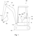
- Fig. 1 schematically illustrates an excavator 100 as a form of a construction machine, viewed from the side.
- the excavator 100 includes a slewable upper structure 101 and an undercarriage 102.
- the slewable upper structure 101 is provided on the undercarriage 102 so as to be slewable.
- the slewable upper structure 101 is equipped with a hydraulic drive system 10 that drives each part of the slewable upper structure 101 by hydraulic pressure.
- the undercarriage 102 includes, for example, crawlers that are placed on the road surface.
- the undercarriage 102 can travel on a road surface with the crawlers driven by a power source such as an engine or an electric motor.
- the traveling means of the undercarriage 102 is not limited to crawlers, but can also be wheels or the like.
- the slewable upper structure 101 includes a cab 103 for an operator and an articulated operation unit 110 operated by the operator.
- the cab 103 is equipped with a seat 107 for the operator and a plurality of control units 108a, 108b such as levers and switches operated by the operator seated on the seat 107.
- the articulated operation unit 110 includes a boom 104, an arm 105, and a bucket 106.
- the boom 104 is connected at its proximal end to the front end of the cab 103 so as to be swingable about a rotating shaft 111a.
- the arm 105 is connected at its proximal end to the distal end of the boom 104 so as to be swingable about a rotating shaft 111b.
- the bucket 106 is connected at its proximal end to the distal end of the arm 105 so as to be swingable about the rotating shaft 111c.
- the articulated operation unit 110 can scoop up, for example, earth, debris or the like, with the bucket 106 by operating the connection parts of the boom 104, the arm 105, and the bucket 106 in a combined manner.
- connection parts of the articulated operation unit 110 are driven by variable displacement motors 12A, 12B, 12C (see Fig. 2 ), which will be described later.
- the connection parts driven by the variable displacement motors 12A, 12B, 12C are driven by directly driving the respective rotating shafts 111a, 111b, 111c (drive parts).
- drive parts the connection parts
- the connection parts may be driven by movable devices different from the rotating shafts 111a, 111b, 111c.
- the bucket 106 attached to the distal end of the articulated operation unit 110 is an example of an attachment.
- the attachment may be, for example, a mechanical fork or a hydraulic breaker instead of the bucket 106.
- Fig. 2 is a circuit diagram of the hydraulic drive system 10 according to the embodiment.
- the hydraulic drive system 10 can operate, for example, any of the connection parts (drive parts) of the articulated operation unit 110 of the excavator 100 simultaneously or individually.
- the hydraulic drive system 10 includes a hydraulic pump 1 that discharges hydraulic fluid, variable displacement motors 12A, 12B, 12C that receive pressure of the hydraulic fluid discharged from the hydraulic pump 1 and operate corresponding drive parts, and a controller 90 (control unit) that controls the displacement varying parts 13 of the variable displacement motors 12A, 12B, 12C.
- the variable displacement motors 12A, 12B, 12C have a respective output shaft (not shown).
- variable displacement motors 12A, 12B, 12C Between the output shafts of the variable displacement motors 12A, 12B, 12C and the drive parts, there are provided speed reducers (not shown) for reducing the rotational speed of the output shafts.
- the variable displacement motors 12A, 12B, 12C constitute variable displacement actuators.
- the hydraulic pump 1 is driven by a power source such as an engine or an electric motor.
- the hydraulic pump 1 discharges the hydraulic fluid stored in a tank 2 toward a main feed channel 14 of a hydraulic circuit 3.
- a relief valve 4 is provided upstream of the main feed channel 14 in the hydraulic circuit 3 to control excessive pressure rises in the hydraulic circuit 3.
- the hydraulic fluid drained from the relief valve 4 is returned to the tank 2.
- a diaphragm 5 is provided downstream of the main feed channel 14.
- the diaphragm 5 is connected at its downstream side to a return passage 6 for returning the hydraulic fluid from the main feed channel 14 to the tank 2.
- the hydraulic circuit 3 includes a plurality (three) of branch passages 7A, 7B, 7C that branch off from the main feed channel 14.
- the branch passages 7A, 7B, 7C have corresponding variable displacement motors 12A, 12B, 12C provided thereon.
- Each of the branch passages 7A, 7B, 7C is connected at its upstream side to the main feed channel 14 via a diaphragm part 8 and connected at its downstream side to the return passage 6.
- the branch passages 7A, 7B, 7C are provided with channel-switching valves 15A, 15B, 15C, respectively, that extend across the portion connected to the main feed channel 14 and the portion connected to the return passage 6.
- the channel-switching valves 15A, 15B, 15C are formed of solenoid valves or the like that have four ports and can be switched to three positions. Specifically, these solenoid valves can be switched among two positions for switching the direction of the flow of the hydraulic fluid fed toward the variable displacement motors 12A, 12B, 12C and one position (stop position) for stopping the flow of the hydraulic fluid into the variable displacement motors 12A, 12B, 12C.
- the direction of rotation of the variable displacement motors 12A, 12B, 12C can be switched between the forward direction and the reverse direction by changing the direction of the flow of the hydraulic fluid by means of the channel-switching valves 15A, 15B, and 15C.
- variable displacement motors 12A, 12B, and 12C stop rotating by the channel-switching valves 15A, 15B, 15C switched to the stop position.
- Each of the channel-switching valves 15A, 15B, 15C is switched to one of the above three positions upon receiving a switching instruction from the controller 90.
- the variable displacement motors 12A, 12B, 12C are formed, for example, of a swash plate axial plunger motor having a swash plate of which the inclination angle can be adjusted as desired.
- This axial plunger motor has a well-known structure in which the inflow and outflow capacity of the hydraulic fluid by the plunger is varied by changing the inclination angle of the swash plate that regulates an advance/retreat stroke of the plunger.
- the inclination angle of the swash plate of the variable displacement motors 12A, 12B, 12C is changed by the actuators 50A, 50B, 50C for changing the inclination angle.
- the actuators 50A, 50B, 50C are controlled by the controller 90.
- the actuators 50A, 50B, and 50C are not limited to a specific structure as long as they can change the inclination angle of the swash plate to any angle upon receiving a control instruction from the controller 90.
- the actuators 50A, 50B, 50C may change the inclination angle of the swash plate by hydraulic pressure or by an electric motor or an electromagnetic actuator.
- variable displacement motors 12A, 12B, 12C are formed of swash plate axial plunger motors, but this example is not limitative.
- the variable displacement motors 12A, 12B, 12C may have any structure as long as they are hydraulic motors that can vary the inflow and outflow capacity of the hydraulic fluid based on an operation instruction from the controller 90.
- the variable displacement motors 12A, 12B, 12C may be radial plunger motors or the like.
- a radial plunger motor includes a rotating block with a plurality of plungers arranged radially and a stroke regulation ring located outside the rotating block, and the inflow and outflow capacity of the plungers can be varied by changing the eccentricity of the stroke regulation ring.
- the type of the motors is not limited to the plunger type, but can be various types, such as the vane type or the gear type, for example.
- variable displacement motors 12A, 12B, 12C described above receive the pressure of the hydraulic fluid discharged from the hydraulic pump 1 and operate a plurality of connection parts (drive parts) of the articulated operation unit 110 of the excavator 100, for example.
- the channel switching valves 15A, 15B, 15C are switched to open one of the branch passages 7A, 7B, 7C corresponding to the drive part to be operated and close the other two branch passages.
- the displacement of the variable displacement motors 12A, 12B, 12C to be operated and the pressure in the main feed channel 14 are controlled by the controller 90 to achieve the preset work capacity.
- the hydraulic fluid having been used to operate one of the drive parts returns to the tank 2 through the return passage 6.
- the operating direction of the drive part (the direction of rotation of the rotating shaft) operated at this time can be changed as needed by switching the position of the channel-switching valves 15A, 15B, 15C between two positions.
- Each of the branch passages 7A, 7B, 7C has pressure sensors p1, p2 installed thereon for detecting the pressure of the hydraulic fluid.
- the pressure sensors p1, p2 are installed on the upstream portion and the downstream portion of the branch passages 7A, 7B, 7C with the variable displacement motors 12A, 12B, 12C in between.
- the pressure sensors p1, p2 are used separately in accordance with the direction of rotation of the variable displacement motors 12A, 12B, 12C, to sense the pressure in the fluid inflow part (high pressure side) of the variable displacement motors 12A, 12B, 12C.
- the sensing signals (the pressure of the hydraulic fluid) obtained by the pressure sensors p1, p2 are input to the controller 90.
- the controller 90 controls each part of the hydraulic drive system 10 based on the sensing signals from the pressure sensors p1, p2.
- the channel-switching valves 15A, 15B, 15C are switched to open all branch passages 7A, 7B, 7C. This allows the hydraulic fluid flowing into the branch passages 7A, 7B, 7C to be fed to the corresponding variable displacement motors 12A, 12B, 12C.
- the hydraulic fluid having been used to operate all the drive parts returns to the tank 2 through the return passage 6.
- the pressure in the fluid inflow part of each of the branch passages 7A, 7B, 7C (the upstream side of each of the variable displacement motors 12A, 12B, 12C) is sensed by one of the pressure sensors p1, p2.
- the sensing signals are input to the controller 90.
- the controller 90 receives the sensing signals and controls the displacement varying parts (e.g., the inclination varying parts of the swash plates) of the variable displacement motors 12A, 12B, 12C such that the pressures in the fluid inflow parts of the variable displacement motors 12A, 12B, 12C approach a common target pressure (target pressure).
- the target pressure can be set and adjusted by the controller 90.
- the target pressure may be set, for example, at 70 to 80% of the maximum pressure in the fluid inflow parts of the variable displacement motors 12A, 12B, 12C, which require the maximum flow rate to operate the drive parts. In this case, the required flow rate of each drive part can be reduced, and thus energy consumption can be reduced.
- the target pressure may also be set at about 50% of the maximum system pressure. In this case, the variation of displacement of the variable displacement motors 12A, 12B, 12C can be minimized.
- Fig. 3 shows the pressure and flow rate (flow rate of consumed hydraulic fluid) of the fluid inflow parts of the three variable displacement motors 12A, 12B, 12C in the case where all (three) drive parts are operated simultaneously.
- the pressure on the fluid inflow part side of each of the variable displacement motors 12A, 12B, 12C turns nearly uniform to approach the target pressure, as shown in Fig. 3 .
- This provides each of the variable displacement motors 12A, 12B, 12C with the hydraulic fluid at the flow rate required for the drive part.
- the overall consumed energy of the hydraulic fluid is reduced significantly, as shown in Fig. 3 .
- the sections 12Ac, 12Bc, 12Cc shown by the two dotted lines in Fig. 3 indicate the pressure and flow rate (flow rate of consumed hydraulic fluid) in the inflow parts in the case where the displacement of each motor is constant (the case where variable displacement motors 12A, 12B, 12C are not employed).
- the channel switching valves 15A, 15B, 15C are switched to open two of the branch passages 7A, 7B, 7C shown in Fig. 2 corresponding to the two drive parts and close the remaining one branch passage.
- the pressure in the fluid inflow part of each of the two opened branch passages among the branch passages 7A, 7B, 7C (the upstream side of each of the variable displacement motors 12A, 12B, 12C) is sensed by one of the pressure sensors p1, p2.
- the sensing signals are input to the controller 90.
- the controller 90 receives the sensing signals and controls the displacement varying parts 13 of the two variable displacement motors such that the pressures in the fluid inflow parts of the two variable displacement motors among the variable displacement motors 12A, 12B, 12C approach a common target pressure (target pressure).
- target pressure target pressure
- each of the two variable displacement motors consumes the hydraulic fluid at a predetermined flow rate, with the pressure in each fluid inflow part maintained close to the target pressure.
- the overall consumed energy of the hydraulic fluid is also reduced.
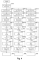
- Fig. 4 shows the flow of control in the case where all (three) drive parts are operated simultaneously.
- each step is denoted by a three-digit number (e.g., S102) followed by a hyphen ("-") and an attached number.
- This attached number refers to relationship to the variable displacement motors 12A, 12B, 12C.
- the steps related to variable displacement motor 12A are marked with the numeral "1" following the hyphen ("-")
- the steps related to variable displacement motor 12B are marked with the numeral "2" following the hyphen ("-")
- the steps related to variable displacement motor 12C are marked with the numeral "3" following the hyphen ("-").
- the steps related to the variable displacement motors 12A, 12B, 12C have almost the same content, so the steps related to variable displacement motor 12A are described in detail below as a representative, and the steps related to the other variable displacement motors 12B and 12C are omitted from detailed description.
- step S101 the target drive pressure Pt (target pressure) is set.
- step S102-1 the rated maximum displacement V1max (hereinafter referred to as "the maximum displacement V1max”) of the variable displacement motor 12A is set.
- the maximum displacement V1 max is, for example, a value stored in the memory in advance and read in.
- step S103-1 the rated minimum displacement V1min (hereinafter referred to as "the minimum displacement V1min") of the variable displacement motor 12A is set.
- the minimum displacement V1min is, for example, a value stored in the memory in advance and read in.
- step S104-1 the actual pressure P1 on the fluid inflow part side of the variable displacement motor 12A as sensed by the pressure sensor p1 or p2 is read.
- step S105-1 the displacement setting value V1 of the variable displacement motor 12A used when the control signal was output previous time is multiplied by the ratio of the actual sensed pressure P1 to the target drive pressure Pt to obtain the next displacement setting value V1.
- an appropriate initial value e.g., maximum displacement V1max
- V1 maximum displacement V1max
- step S106-1 it is determined whether or not the calculated value V1 is greater than or equal to the maximum displacement V1max, and if it is greater than or equal to the maximum displacement V1max (if YES), the process proceeds to step S107-1, where the value of the maximum displacement V1max is assigned to the value V1. If the calculated value V1 is smaller than the maximum displacement V1max (if NO), the process proceeds to step S108-1.
- step S108-1 it is determined whether or not the calculated value V1 is equal to or smaller than the minimum displacement V1min, and if it is equal to or smaller than the minimum displacement V1min (if YES), the process proceeds to step S109-1, where the value of the minimum displacement V1min is assigned to the value V1, and then the process proceeds to step S110-1. If the calculated value V1 is greater than the minimum displacement V1min (if NO), the calculated value of step S105-1 is assigned to the value V1, and the process proceeds to step S110-1.
- step S110-1 the setting value V1 is updated with the value V1 determined in steps S105-1 to S109-1, and the displacement control signal CS1 corresponding to the updated value V1 is output to the actuator 50A for varying the displacement of the variable displacement motor 12A.
- the processing from step S105-1 to step S110-1 (the processing from step S105-2 to step S110-2 and the processing from step S105-3 to step S110-3), which is enclosed by the broken line in Fig. 4 , are performed in the arithmetic section of the controller 90.
- the actuators 50B, 50C for varying the displacements of the other variable displacement motors 12B, 12C receive from the controller 90 the displacement control signals CS2, CS3 corresponding to the updated values V2, V3 determined in the same manner.
- step S105-1 to step S110-1 the processing from step S105-2 to step S110-2 and the processing from step S105-3 to step S110-3) are repeated in the same manner.
- the displacements of the variable displacement motors 12A, 12B, 12C are varied to the displacements in accordance with the ratio of the actual sensed pressures P1, P2, P3 to the target drive pressure Pt (target pressure).
- the pressure in the fluid inflow part side of each of the variable displacement motors 12A, 12B, 12C approaches the target drive pressure Pt (target pressure).
- the actuators 50A, 50B, 50C for varying the displacements of the variable displacement motors 12A, 12B, 12C will not receive command values for varying the displacements to exceed the rated maximum displacement V1 max of the variable displacement motors 12A, 12B, 12C or command values for varying the displacements to fall below the rated minimum displacement V1min of the variable displacement motors 12A, 12B, 12C.
- variable displacement varying parts 13 of the variable displacement motors 12A, 12B, 12C are controlled by the controller 90 such that the pressures in the fluid inflow parts of the multiple variable displacement motors 12A, 12B, 12C in operation approach a common target pressure.
- This allows the variable displacement motors 12A, 12B, 12C to provide the required amount of work to respective corresponding drive parts, with the pressures in the fluid inflow parts maintained close to the target pressure that is common to the motors.
- the hydraulic drive system 10 when the hydraulic drive system 10 according to this embodiment is employed, it is no longer necessary to discharge much of the hydraulic fluid once pressurized to a high pressure by the hydraulic pump 1 for reducing the pressure in the feed channel for each motor or to reduce the cross-sectional area of the channel to consume the hydraulic fluid as a pressure drop. This makes it possible to reduce energy loss occurring when multiple drive parts are operated simultaneously. Therefore, when the hydraulic drive system 10 according to this embodiment is employed, the hydraulic pump 1 and the power source such as the engine or electric motor for driving the hydraulic pump 1 can have a smaller size and a smaller weight. Therefore, it is advantageous to install the hydraulic drive system 10 in a construction machine such as the excavator 100.
- the controller 90 which serves as the control unit, controls the displacement varying parts 13 of the variable displacement motors 12A, 12B, 12C such that the displacements of the variable displacement motors 12A, 12B, 12C in operation are varied within respective ranges from the rated minimum displacements to the rated maximum displacements of the variable displacement motors 12A, 12B, 12C.
- the actuators 50A, 50B, 50C for operating the displacement varying parts 13 of the variable displacement motors 12A, 12B, 12C will not receive command values for varying the displacements to exceed the rated maximum displacements of the variable displacement motors 12A, 12B, 12C or command values for varying the displacements to fall below the rated minimum displacements of the variable displacement motors 12A, 12B, 12C. Therefore, when the hydraulic drive system 10 according to this embodiment is employed, it is possible to inhibit excessive load from acting on the actuators 50A, 50B, 50C.
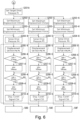
- Figs. 5 and 6 are flowcharts showing an example of control of the hydraulic drive system according to another embodiment.
- the hydraulic drive system 10 according to the above embodiment by way of an example, three variable displacement motors 12A, 12B, 12C are arranged in one hydraulic circuit 3.
- the hydraulic drive system according to this embodiment includes, by way of an example, a total of six variable displacement motors, three each in two hydraulic circuits.
- Each of the hydraulic circuits has the same configuration as in the above embodiment and is separately equipped with a hydraulic pump.
- Fig. 5 shows the steps of controlling the three variable displacement motors in the first hydraulic circuit.
- Fig. 6 shows the steps of controlling the three variable displacement motors in the second hydraulic circuit.
- step S201 shown in Fig. 5 the target drive pressure Pt (target pressure) in the first hydraulic circuit is set.
- step S201A shown in Fig. 6 the target drive pressure Pt (target pressure) in the second hydraulic circuit is set.
- the method of generating the displacement control signals CS1 to CS6 in these hydraulic circuits is the same as in the above embodiment.
- the steps related to the first, second, and third variable displacement motors provided in the first hydraulic circuit are marked with the numerals "1," "2,” and “3” following the hyphen ("-"), respectively.
- the steps related to the fourth, fifth, and sixth variable displacement motors provided in the second hydraulic circuit are marked with the numerals "4,” "5,” and “6” following the hyphen ("-"), respectively.
- the same numbers are used for variables in the steps related to each variable displacement motor.
- the contents of the steps related to each variable displacement motor are all the same as in steps S102-1 to S110-1 of the above embodiment. Therefore, the details of each step are not described.
- the steps that correspond to the steps in the above embodiment are marked with a three-digit number starting with "2" in place of "1.”
- the hydraulic drive system performs the same displacement control as in the above embodiment for each of the three variable displacement motors in the two hydraulic circuits.
- the displacement varying parts of the variable displacement motors are controlled by the controller such that the pressures in the fluid inflow parts of the multiple variable displacement motors operated in each hydraulic circuit approach a common target drive pressure Pt (target pressure). Therefore, in the hydraulic drive system according to this embodiment, even when more drive parts are operated simultaneously than in the above embodiment, energy loss can be likewise reduced by controlling the displacement varying parts of the variable displacement motors as described above.
- the controller which serves as the control unit, performs the following control (a) and (b) when operating multiple drive parts simultaneously.
- the controller controls the displacement varying part of each variable displacement motor such that the pressure in the fluid inflow part of each variable displacement motor in operation approaches a common target pressure.
- the controller 90 controls the displacement varying parts of the variable displacement motors such that the displacements of the variable displacement motors in operation are varied within respective ranges from the rated minimum displacements to the rated maximum displacements of the variable displacement motors.
- the controller which serves as the control unit, may perform the following control (c) in addition to or instead of (a) and (b) above when operating multiple drive parts simultaneously. (c)
- the controller controls the displacement varying parts of variable displacement motors such that the overall flow rate of the variable displacement motors in operation is equal to or less than a prescribed flow rate.
- a coefficient A is set as in Formula (1) below.
- A Vp / V 1 + V 2 + V 3 ⁇ C C: fixed coefficient
- V1 A ⁇ V1
- V2 AxV2
- V3 AxV3 ....
- This step can be added, for example, in the flowchart of Fig. 4 after the steps S105-1, S105-2, S105-3 .... Addition of this step makes it possible to control the displacement varying parts of the variable displacement motors such that the overall flow rate of the variable displacement motors in operation is equal to or less than the prescribed flow rate Vp.
- the controller controls the displacement varying parts of variable displacement motors such that the overall flow rate of the variable displacement motors in operation is equal to or less than the prescribed flow rate Vp.
- the controller which serves as the control unit, may perform the following control (d) in addition to (a), (b), and (c) above when operating multiple drive parts simultaneously. It is also possible that the following control (d) is performed in place of the control (b) + (c) above, or in place of one of controls (b) and (c) above, (d)
- the controller controls the displacement varying parts of the variable displacement motors such that the overall horsepower of the variable displacement motors in operation is equal to or less than a prescribed horsepower.
- a coefficient B W / P 1 ⁇ V 1 ⁇ N 1 + P 2 ⁇ V 2 ⁇ N 2 + P 3 ⁇ V 2 ⁇ V 3 ⁇ C
- the controller controls the displacement varying parts of variable displacement motors such that the overall horsepower of the variable displacement motors in operation is equal to or less than the prescribed horsepower W.
- variable displacement actuators 12A, 12B, 12C are not limited to the variable displacement motors 12A, 12B, 12C.
- the variable displacement actuators can be direct-acting cylinder devices or the like as long as they are hydraulic actuators capable of varying the displacement.
- the hydraulic drive system is applied to the excavator 100, which is a construction machine, but the hydraulic drive system can also be applied to construction machines other than the excavator 100. Furthermore, the application of the hydraulic drive system is not limited to construction machines, but it can also be applied to other apparatuses driven by multiple hydraulic actuators.
- a member formed of multiple components may be integrated into a single component, or conversely, a member formed of a single component may be divided into multiple components. Irrespective of whether or not the components are integrated, they are acceptable as long as they are configured to attain the object of the invention.
Landscapes
- Engineering & Computer Science (AREA)
- General Engineering & Computer Science (AREA)
- Mining & Mineral Resources (AREA)
- Civil Engineering (AREA)
- Structural Engineering (AREA)
- Physics & Mathematics (AREA)
- Fluid Mechanics (AREA)
- Mechanical Engineering (AREA)
- Fluid-Pressure Circuits (AREA)
- Operation Control Of Excavators (AREA)
Applications Claiming Priority (1)
| Application Number | Priority Date | Filing Date | Title |
|---|---|---|---|
| JP2022190160A JP2024077919A (ja) | 2022-11-29 | 2022-11-29 | 液圧駆動システム、及び、建設機械 |
Publications (1)
| Publication Number | Publication Date |
|---|---|
| EP4379151A1 true EP4379151A1 (de) | 2024-06-05 |
Family
ID=88558490
Family Applications (1)
| Application Number | Title | Priority Date | Filing Date |
|---|---|---|---|
| EP23206047.5A Pending EP4379151A1 (de) | 2022-11-29 | 2023-10-26 | Hydraulisches antriebssystem und baumaschine |
Country Status (4)
| Country | Link |
|---|---|
| US (1) | US12247373B2 (de) |
| EP (1) | EP4379151A1 (de) |
| JP (1) | JP2024077919A (de) |
| CN (1) | CN118110702A (de) |
Citations (5)
| Publication number | Priority date | Publication date | Assignee | Title |
|---|---|---|---|---|
| JP2005147257A (ja) * | 2003-11-14 | 2005-06-09 | Kayaba Ind Co Ltd | 油圧制御装置 |
| EP2351937A1 (de) * | 2008-10-22 | 2011-08-03 | Caterpillar SARL | Hdraulisches steuersystem für eine bearbeitungsmaschine |
| US20160144893A1 (en) * | 2014-11-26 | 2016-05-26 | Linde Hydraulics Gmbh & Co. Kg | Hydrostatic Traction Drive System |
| EP2681365B1 (de) * | 2011-03-03 | 2018-05-09 | Clark Equipment Company | Automatisiertes schalten eines hydraulischen antriebssystems |
| JP2020204172A (ja) | 2019-06-14 | 2020-12-24 | 株式会社小松製作所 | 作業機械 |
Family Cites Families (6)
| Publication number | Priority date | Publication date | Assignee | Title |
|---|---|---|---|---|
| US3874173A (en) * | 1973-06-04 | 1975-04-01 | Bernard Charles Wilkins | Hydrostatic power transmission system |
| US3992883A (en) * | 1975-10-01 | 1976-11-23 | Lucas Industries Limited | Fan drive systems |
| US4769991A (en) * | 1987-02-19 | 1988-09-13 | Deere & Company | Balanced hydraulic propulsion system |
| JPH082269A (ja) * | 1994-06-21 | 1996-01-09 | Komatsu Ltd | 油圧駆動式走行装置の走行制御回路 |
| US7043907B2 (en) * | 2002-07-11 | 2006-05-16 | Nabtesco Corporation | Electro-hydraulic actuation system |
| DE102010031835A1 (de) * | 2010-07-22 | 2012-01-26 | Liebherr-Werk Nenzing Gmbh | Lüfterregelung |
-
2022
- 2022-11-29 JP JP2022190160A patent/JP2024077919A/ja active Pending
-
2023
- 2023-10-24 CN CN202311386496.6A patent/CN118110702A/zh active Pending
- 2023-10-26 EP EP23206047.5A patent/EP4379151A1/de active Pending
- 2023-10-27 US US18/496,276 patent/US12247373B2/en active Active
Patent Citations (5)
| Publication number | Priority date | Publication date | Assignee | Title |
|---|---|---|---|---|
| JP2005147257A (ja) * | 2003-11-14 | 2005-06-09 | Kayaba Ind Co Ltd | 油圧制御装置 |
| EP2351937A1 (de) * | 2008-10-22 | 2011-08-03 | Caterpillar SARL | Hdraulisches steuersystem für eine bearbeitungsmaschine |
| EP2681365B1 (de) * | 2011-03-03 | 2018-05-09 | Clark Equipment Company | Automatisiertes schalten eines hydraulischen antriebssystems |
| US20160144893A1 (en) * | 2014-11-26 | 2016-05-26 | Linde Hydraulics Gmbh & Co. Kg | Hydrostatic Traction Drive System |
| JP2020204172A (ja) | 2019-06-14 | 2020-12-24 | 株式会社小松製作所 | 作業機械 |
Also Published As
| Publication number | Publication date |
|---|---|
| CN118110702A (zh) | 2024-05-31 |
| US20240175242A1 (en) | 2024-05-30 |
| US12247373B2 (en) | 2025-03-11 |
| JP2024077919A (ja) | 2024-06-10 |
Similar Documents
| Publication | Publication Date | Title |
|---|---|---|
| JP4067596B2 (ja) | 建設機械の油圧制御装置 | |
| KR100915207B1 (ko) | 중장비용 유압회로 | |
| US6176083B1 (en) | Apparatus and method for controlling displacement of steering pump for work vehicle | |
| EP3505688B1 (de) | System zur steuerung einer baumaschine und verfahren zur steuerung einer baumaschine | |
| KR20070043808A (ko) | 유압시스템과 그러한 시스템으로 구성되는 작업기계 | |
| JPH10141310A (ja) | 圧油供給装置 | |
| EP1790551A1 (de) | Hydraulische antriebsvorrichtung für arbeitsfahrzeug | |
| EP1743980B1 (de) | Hydraulikbagger mit hydraulischem steuergerät | |
| EP3885586B1 (de) | Antriebsvorrichtung für hydraulikzylinder in einer arbeitsmaschine | |
| EP1750017B1 (de) | Fahrsystem für schwere Baumaschine | |
| CN101687464A (zh) | 液压驱动车辆 | |
| JPH11336136A (ja) | 建設機械のエンジン回転数制御装置 | |
| CN114919645B (zh) | 液压驱动系统 | |
| EP3640404B1 (de) | Verfahren und vorrichtung zur steuerung der fahrgeschwindigkeit einer baumaschine | |
| US10927867B2 (en) | Work machine having hydraulics for energy recovery | |
| KR100194701B1 (ko) | 유압제어장치 | |
| EP4379151A1 (de) | Hydraulisches antriebssystem und baumaschine | |
| JP3917257B2 (ja) | 油圧作業機の油圧回路装置 | |
| JPH07167104A (ja) | 可変容量型油圧ポンプ制御装置 | |
| JP2016205451A (ja) | 流体圧回路および作業機械 | |
| JP4724945B2 (ja) | 油圧回路 | |
| JP2555287B2 (ja) | 油圧制御装置 | |
| JP4381781B2 (ja) | 建設機械のポンプ制御装置 | |
| JPH0941427A (ja) | 油圧作業機 | |
| EP3608548B1 (de) | Baumaschine |
Legal Events
| Date | Code | Title | Description |
|---|---|---|---|
| PUAI | Public reference made under article 153(3) epc to a published international application that has entered the european phase |
Free format text: ORIGINAL CODE: 0009012 |
|
| STAA | Information on the status of an ep patent application or granted ep patent |
Free format text: STATUS: REQUEST FOR EXAMINATION WAS MADE |
|
| 17P | Request for examination filed |
Effective date: 20231026 |
|
| AK | Designated contracting states |
Kind code of ref document: A1 Designated state(s): AL AT BE BG CH CY CZ DE DK EE ES FI FR GB GR HR HU IE IS IT LI LT LU LV MC ME MK MT NL NO PL PT RO RS SE SI SK SM TR |
|
| RAP1 | Party data changed (applicant data changed or rights of an application transferred) |
Owner name: COMTESCO CORPORATION |