EP4379932A1 - Bloc-batterie et dispositif comprenant ledit bloc-batterie - Google Patents
Bloc-batterie et dispositif comprenant ledit bloc-batterie Download PDFInfo
- Publication number
- EP4379932A1 EP4379932A1 EP22890267.2A EP22890267A EP4379932A1 EP 4379932 A1 EP4379932 A1 EP 4379932A1 EP 22890267 A EP22890267 A EP 22890267A EP 4379932 A1 EP4379932 A1 EP 4379932A1
- Authority
- EP
- European Patent Office
- Prior art keywords
- battery
- battery module
- venting
- frame
- flow path
- Prior art date
- Legal status (The legal status is an assumption and is not a legal conclusion. Google has not performed a legal analysis and makes no representation as to the accuracy of the status listed.)
- Pending
Links
Images




Classifications
-
- H—ELECTRICITY
- H01—ELECTRIC ELEMENTS
- H01M—PROCESSES OR MEANS, e.g. BATTERIES, FOR THE DIRECT CONVERSION OF CHEMICAL ENERGY INTO ELECTRICAL ENERGY
- H01M50/00—Constructional details or processes of manufacture of the non-active parts of electrochemical cells other than fuel cells, e.g. hybrid cells
- H01M50/30—Arrangements for facilitating escape of gases
-
- H—ELECTRICITY
- H01—ELECTRIC ELEMENTS
- H01M—PROCESSES OR MEANS, e.g. BATTERIES, FOR THE DIRECT CONVERSION OF CHEMICAL ENERGY INTO ELECTRICAL ENERGY
- H01M50/00—Constructional details or processes of manufacture of the non-active parts of electrochemical cells other than fuel cells, e.g. hybrid cells
- H01M50/30—Arrangements for facilitating escape of gases
- H01M50/394—Gas-pervious parts or elements
-
- H—ELECTRICITY
- H01—ELECTRIC ELEMENTS
- H01M—PROCESSES OR MEANS, e.g. BATTERIES, FOR THE DIRECT CONVERSION OF CHEMICAL ENERGY INTO ELECTRICAL ENERGY
- H01M50/00—Constructional details or processes of manufacture of the non-active parts of electrochemical cells other than fuel cells, e.g. hybrid cells
- H01M50/30—Arrangements for facilitating escape of gases
- H01M50/383—Flame arresting or ignition-preventing means
-
- H—ELECTRICITY
- H01—ELECTRIC ELEMENTS
- H01M—PROCESSES OR MEANS, e.g. BATTERIES, FOR THE DIRECT CONVERSION OF CHEMICAL ENERGY INTO ELECTRICAL ENERGY
- H01M50/00—Constructional details or processes of manufacture of the non-active parts of electrochemical cells other than fuel cells, e.g. hybrid cells
- H01M50/20—Mountings; Secondary casings or frames; Racks, modules or packs; Suspension devices; Shock absorbers; Transport or carrying devices; Holders
- H01M50/204—Racks, modules or packs for multiple batteries or multiple cells
-
- H—ELECTRICITY
- H01—ELECTRIC ELEMENTS
- H01M—PROCESSES OR MEANS, e.g. BATTERIES, FOR THE DIRECT CONVERSION OF CHEMICAL ENERGY INTO ELECTRICAL ENERGY
- H01M50/00—Constructional details or processes of manufacture of the non-active parts of electrochemical cells other than fuel cells, e.g. hybrid cells
- H01M50/20—Mountings; Secondary casings or frames; Racks, modules or packs; Suspension devices; Shock absorbers; Transport or carrying devices; Holders
- H01M50/204—Racks, modules or packs for multiple batteries or multiple cells
- H01M50/207—Racks, modules or packs for multiple batteries or multiple cells characterised by their shape
- H01M50/209—Racks, modules or packs for multiple batteries or multiple cells characterised by their shape adapted for prismatic or rectangular cells
-
- H—ELECTRICITY
- H01—ELECTRIC ELEMENTS
- H01M—PROCESSES OR MEANS, e.g. BATTERIES, FOR THE DIRECT CONVERSION OF CHEMICAL ENERGY INTO ELECTRICAL ENERGY
- H01M50/00—Constructional details or processes of manufacture of the non-active parts of electrochemical cells other than fuel cells, e.g. hybrid cells
- H01M50/20—Mountings; Secondary casings or frames; Racks, modules or packs; Suspension devices; Shock absorbers; Transport or carrying devices; Holders
- H01M50/204—Racks, modules or packs for multiple batteries or multiple cells
- H01M50/207—Racks, modules or packs for multiple batteries or multiple cells characterised by their shape
- H01M50/211—Racks, modules or packs for multiple batteries or multiple cells characterised by their shape adapted for pouch cells
-
- H—ELECTRICITY
- H01—ELECTRIC ELEMENTS
- H01M—PROCESSES OR MEANS, e.g. BATTERIES, FOR THE DIRECT CONVERSION OF CHEMICAL ENERGY INTO ELECTRICAL ENERGY
- H01M50/00—Constructional details or processes of manufacture of the non-active parts of electrochemical cells other than fuel cells, e.g. hybrid cells
- H01M50/30—Arrangements for facilitating escape of gases
- H01M50/342—Non-re-sealable arrangements
-
- H—ELECTRICITY
- H01—ELECTRIC ELEMENTS
- H01M—PROCESSES OR MEANS, e.g. BATTERIES, FOR THE DIRECT CONVERSION OF CHEMICAL ENERGY INTO ELECTRICAL ENERGY
- H01M50/00—Constructional details or processes of manufacture of the non-active parts of electrochemical cells other than fuel cells, e.g. hybrid cells
- H01M50/30—Arrangements for facilitating escape of gases
- H01M50/342—Non-re-sealable arrangements
- H01M50/3425—Non-re-sealable arrangements in the form of rupturable membranes or weakened parts, e.g. pierced with the aid of a sharp member
-
- H—ELECTRICITY
- H01—ELECTRIC ELEMENTS
- H01M—PROCESSES OR MEANS, e.g. BATTERIES, FOR THE DIRECT CONVERSION OF CHEMICAL ENERGY INTO ELECTRICAL ENERGY
- H01M50/00—Constructional details or processes of manufacture of the non-active parts of electrochemical cells other than fuel cells, e.g. hybrid cells
- H01M50/30—Arrangements for facilitating escape of gases
- H01M50/35—Gas exhaust passages comprising elongated, tortuous or labyrinth-shaped exhaust passages
- H01M50/358—External gas exhaust passages located on the battery cover or case
-
- H—ELECTRICITY
- H01—ELECTRIC ELEMENTS
- H01M—PROCESSES OR MEANS, e.g. BATTERIES, FOR THE DIRECT CONVERSION OF CHEMICAL ENERGY INTO ELECTRICAL ENERGY
- H01M2200/00—Safety devices for primary or secondary batteries
- H01M2200/20—Pressure-sensitive devices
-
- Y—GENERAL TAGGING OF NEW TECHNOLOGICAL DEVELOPMENTS; GENERAL TAGGING OF CROSS-SECTIONAL TECHNOLOGIES SPANNING OVER SEVERAL SECTIONS OF THE IPC; TECHNICAL SUBJECTS COVERED BY FORMER USPC CROSS-REFERENCE ART COLLECTIONS [XRACs] AND DIGESTS
- Y02—TECHNOLOGIES OR APPLICATIONS FOR MITIGATION OR ADAPTATION AGAINST CLIMATE CHANGE
- Y02E—REDUCTION OF GREENHOUSE GAS [GHG] EMISSIONS, RELATED TO ENERGY GENERATION, TRANSMISSION OR DISTRIBUTION
- Y02E60/00—Enabling technologies; Technologies with a potential or indirect contribution to GHG emissions mitigation
- Y02E60/10—Energy storage using batteries
Definitions
- the present disclosure relates to a battery pack and a device including the same, and more particularly, to a battery pack that can prevent external ignition phenomena, and a device including the same.
- chargeable/dischargeable secondary batteries are used as a power source for an electric vehicle (EV), a hybrid electric vehicle (HEV), a plug-in hybrid electric vehicle (P-HEV) and the like, in an attempt to solve air pollution and the like caused by existing gasoline vehicles using fossil fuel. Therefore, the demand for development of the secondary battery is growing.
- EV electric vehicle
- HEV hybrid electric vehicle
- P-HEV plug-in hybrid electric vehicle
- the lithium secondary battery has come into the spotlight because they have advantages, for example, being freely charged and discharged, and having very low self-discharge rate and high energy density.
- a secondary battery used for small-sized devices two to three battery cells are used, but in the case of a secondary battery used for a middle or large-sized device such as an automobile, a battery module or a battery pack in which a large number of battery cells are electrically connected is used.
- Fig. 1 shows a state before and after an ignition phenomenon of a mesh formed in a conventional battery pack.
- Battery cells mounted in battery modules or battery packs can generate a large amount of heat in a charge and discharge process. If the temperature becomes higher than the proper temperature due to reasons such as overcharging, performance may deteriorate, and if the temperature rise is excessive, it may cause explosion or ignition. When the battery cell ignites, internal materials of the cell may be ejected along with high-temperature inflammable gas to the outside of the battery module or the battery pack. Such internal materials are mainly materials such as C, Cu, Al, Ni, Co, Mg, and Li, and are ejected in the form of high-temperature particles, that is, sparks.
- a battery pack comprising: a battery module including a plurality of battery cells, and a pack frame that houses the battery module, wherein a venting flow path for discharging gas generated from the battery module is provided between the battery module and the pack frame, and wherein a filter mesh is formed on a lower surface of the venting flow path.
- the filter mesh may be located parallel to the lower surface of the pack frame.
- the venting flow path may be located so as to be spaced apart from the lower surface of the pack frame.
- a venting part is formed on one surface of the battery module, and the battery module may be arranged so that one surface on which the venting part is formed faces the venting flow path.
- a venting part is formed on one surface of the battery module, and the battery module may be arranged so that one surface of the pack frame and the venting part face each other.
- the venting flow path may be located on the upper side of the venting part.
- the filter mesh may be located on the upper side of the venting part.
- the venting part may be in the form of a plate that is broken at a predetermined pressure or higher.
- the venting part may be in the form of a valve that is opened at a predetermined pressure or higher.
- a device comprising at least one battery pack as described above.
- the battery pack of the present disclosure prevents particles from being releases to the outside of the battery pack, thereby preventing ignition phenomena from being propagated to the outside of the battery pack.
- the upper surface/lower surface of a specific member can be determined differently depending on which direction is used for a reference direction.
- 'upper surface' or 'lower surface' is defined as meaning two surfaces facing each other on the z-axis of the member.
- the side surface may mean a surface that is perpendicular to the upper surface or the lower surface.
- planar it means when a target portion is viewed from the upper side
- cross-sectional it means when a target portion is viewed from the side of a cross section cut vertically.
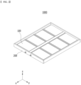
- Fig. 2 is a perspective view of a battery pack according to an embodiment of the present disclosure.
- Fig. 3 is a perspective view of a battery module included in the battery pack according to Fig. 2 .
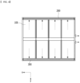
- Fig. 4 is a top view of the battery pack according to Fig. 2 .
- Fig. 5 is a partial cross-sectional view of the battery pack according to Fig. 2 .
- a battery pack 1000 includes at least one battery module 100, a pack frame 200 that houses the at least one battery module 100, and a venting flow path 300 formed between the battery module 100 and the pack frame 200.
- the battery module 100 may include a battery cell stack in which a plurality of battery cells are stacked, a module frame 120 that houses the battery cell stack, a busbar frame that is located on the front surface and/or rear surface of the battery cell stack, a busbar and/or a sensing unit mounted on the busbar frame, and the like.
- the components included in the battery module 100 are not limited thereto, and depending on the design, the battery module 100 may be provided in the state of omitting some of the above-mentioned components, and may be provided in the state of adding other components not mentioned herein.
- the type of battery cells included in the battery module 100 is not particularly limited, and pouch-type, prismatic, or jelly-roll type cylindrical battery cells can all be applied.
- the module frame 120 may include a metal having high thermal conductivity.
- the metal may be aluminum, gold, silver, copper, platinum or an alloy containing these. As the thermal conductivity of the metal is higher, the heat dissipation effect by the module frame improves, so that no specific range for thermal conductivity values is set.
- a venting part 130 may be located on one surface of the module frame 120.
- the venting part 130 can be for discharging gas, sparks, flame, or the like inside the module frame 120.
- the venting part 130 may be located on the lower part of one surface of the module frame 120.
- One surface of the module frame 120 on which the venting part 130 is formed may be a surface facing the electrode leads of the battery cell stack, the busbar frame, or the busbar.
- the shape of the venting part 130 may be varied, and for example, it may be an opening shape.
- the venting part 130 may be in the form of a plate that is broken at a predetermined pressure or higher, such as a rupture disc.
- it may be in the form of a valve that can be opened at a predetermined pressure or higher, such as a relief valve.
- a plurality of battery modules 100 may be provided in the battery pack 1000.
- the plurality of battery modules 100 may be arranged in rows and columns within the pack frame 200.
- the pack frame 200 can be for protecting the battery module 100 and electrical components connected thereto from external physical impact.
- the pack frame 200 may include a lower frame including a lower surface (bottom surface) and a side surface.
- the battery modules 100 are arranged in the inner space of the lower frame formed from the lower surface and the side surface, and then the upper plate or upper frame is coupled with the edge of the lower frame, thereby capable of sealing the pack frame 200.
- the upper plate or upper frame may be interpreted as being included in the pack frame 200, but this is not necessarily the case.
- the pack frame 200 may include a portion having high thermal conductivity in order to quickly dissipate heat generated in the internal space to the outside.
- the pack frame 200 may be made of a metal having high thermal conductivity, and examples thereof may be aluminum, gold, silver, copper, platinum, an alloy containing these, or the like.
- the pack frame 200 may partially have electrical insulation, and an insulating film may be provided at a position where insulation is required, or an insulating coating may be applied.
- a portion of the pack frame 200 to which an insulating film or an insulating coating is applied may be referred to as an insulating portion.
- the venting flow path 300 may be for discharging gas generated from the battery module 100 to the outside of the pack frame 200. As the venting flow path 300 restricts the venting path of gas, it is possible to minimize the influence of the high-temperature gas and the like discharged from the battery module 100 on the adjacent battery module 100.
- the venting flow path 300 may be formed in a separation space between the battery module 100 and the pack frame 200. Flames, gases, and the like discharged from each battery module 100 to the venting flow path 300 move along the venting flow path 300, so that it can be discharged to the outside through a discharge port provided in the pack frame 200.
- the venting flow path 300 may be preferably formed so as to correspond to all battery modules 100 within the battery pack 1000.
- the venting flow path 300 can be formed between the battery modules 100 and the pack frame 200 arranged in each row. Flames, gases, and the like discharged from the battery module 100 may move along the dotted line arrow through the venting flow path 300 to discharged through the discharge port.
- a venting part 130 may be located on one surface of the battery module 100 facing the venting flow path 300.
- the venting part 130 of the battery module 100 may be located toward the venting flow path 300.
- the battery module 100 may be arranged so that one surface on which the venting part 130 is formed faces the venting flow path 300.
- the venting flow path 300 may be formed extendedly along one surface of the pack frame 200 corresponding to the venting part 130.
- the venting flow path 300 is located so as to be spaced apart from the lower surface of the pack frame 200, and an empty space can be formed between the venting flow path 300 and the lower surface of the pack frame 200.
- the venting flow path 300 may be located on an upper side of the venting part 130 of the battery module 100.
- the venting part 130 is located so as to correspond to the empty space, and gas, flame, and the like discharged through the venting part 130 may be discharged into an empty space and then moved to the venting flow path 300 located on the upper side of the empty space.
- a filter mesh 400 may be located in the venting flow path 300.
- the filter mesh 400 may be formed on a lower surface of the venting flow path 300. Gas and flame discharged from the battery module 100 into the empty space may move to the venting flow path 300 through the filter mesh 400.
- the filter mesh 400 may be located parallel to the lower surface of the pack frame 200.
- the filter mesh 400 is arranged parallel to the lower surface of the pack frame 200, the gas and flame discharged from the battery module 100 pass through the filter mesh 400 and move to the venting flow path 300, and the spark may not move through the filter mesh 400.
- the release of high-temperature particles, that is, sparks is restricted by the filter mesh 400, the possibility of the spark coming into contact with external oxygen is lowered, which can prevent further ignition.
- the filter mesh 400 may be spaced apart from the lower surface of the pack frame 200.
- the filter mesh 400 may be located on an upper side of the venting part 130 of the battery module 100.
- the venting flow path 300 of the present embodiment is located on an upper side of the initial movement path of the gas discharged through the venting part 130, and gases and the like discharged from the battery module 100 may move in a direction opposite to gravity and move to the venting flow path 300 via the filter mesh 400. Therefore, particles and the like discharged from the battery module 100 and moved together with the gas can collide with the filter mesh 400 and then fall, thereby being able to prevent the filter mesh 400 from being blocked by particles or the like.
- Figs. 6 and 7 are diagrams for comparing effects according to positions of filters.
- Fig. 6 is an example in which the filter mesh 400 is formed perpendicular to the lower surface of the pack frame 200
- Fig. 7 is an example in which the filter mesh 400 is formed parallel to the lower surface of the pack frame 200.
- the gas or the like discharged from the battery module 100 is moved through the filter mesh 400, and the particles may be restricted in movement by the filter mesh 400 and may not be discharged to the outside.
- the filter mesh 400 of Fig. 6 Since the filter mesh 400 of Fig. 6 is arranged perpendicular to the initial movement direction of the gas discharged from the battery module 100, particles discharged together with the gas can collide with the filter mesh 400 without changing the direction.
- the filter mesh 400 of Fig. 6 has the advantage of effectively collecting a large number of particles, whereas as time passes, the opening of the filter mesh 400 can be blocked by particles, which causes a problem that the gas discharge path is sealed. As the particle closes an opening in the filter mesh 400, internal gas discharge is limited. This, after a predetermined time has elapsed, the opening of the filter mesh 400 may be closed, and the internal pressure of the battery pack 1000 increases, which may cause collapse or explosion of the pack frame 200.
- the filter mesh 400 of Fig. 7 is arranged parallel to the initial movement direction of the gas discharged from the battery module 100, particles discharged together with the gas may rise in a direction opposite to gravity and collide with the filter mesh 400. Therefore, when the filter mesh 400 is formed as shown in Fig. 7 , the particle is unlikely to collide with the filter mesh 400, or even if it collides, it may lose energy and fall.
- the filter mesh 400 of Fig. 7 may be less likely to be blocked by particles than the filter mesh 400 of Fig. 6 , which can minimize collapse or explosion problems of the pack frame 200 due to the closing of the filter mesh 400.
- the filter mesh 400 can be densely formed to have smaller openings.
- the filter mesh 400 may be desirable to form with a slightly large opening to prevent closure, but when it is provided in the form of Fig. 7 , such limitation is not necessary, which is thus advantageous for various designs.
- the battery pack according to one embodiment of the present disclosure may further include a battery management system (BMS) and/or a cooling device that control and manage battery's temperature, voltage, etc.
- BMS battery management system
- a cooling device that control and manage battery's temperature, voltage, etc.
- the battery pack according to an embodiment of the present disclosure can be applied to various devices.
- the device to which the battery pack is applied may be a vehicle means such as an electric bicycle, an electric vehicle, or a hybrid vehicle, but the above-mentioned device is not limited thereto, and the battery pack according to the present embodiment can be used for various devices in addition to the above illustrations, which also falls within the scope of the present disclosure.
Landscapes
- Chemical & Material Sciences (AREA)
- Chemical Kinetics & Catalysis (AREA)
- Electrochemistry (AREA)
- General Chemical & Material Sciences (AREA)
- Gas Exhaust Devices For Batteries (AREA)
- Battery Mounting, Suspending (AREA)
Applications Claiming Priority (2)
| Application Number | Priority Date | Filing Date | Title |
|---|---|---|---|
| KR1020210149627A KR102876311B1 (ko) | 2021-11-03 | 2021-11-03 | 전지 팩 및 이를 포함하는 디바이스 |
| PCT/KR2022/016489 WO2023080532A1 (fr) | 2021-11-03 | 2022-10-26 | Bloc-batterie et dispositif comprenant ledit bloc-batterie |
Publications (2)
| Publication Number | Publication Date |
|---|---|
| EP4379932A1 true EP4379932A1 (fr) | 2024-06-05 |
| EP4379932A4 EP4379932A4 (fr) | 2025-03-19 |
Family
ID=86241418
Family Applications (1)
| Application Number | Title | Priority Date | Filing Date |
|---|---|---|---|
| EP22890267.2A Pending EP4379932A4 (fr) | 2021-11-03 | 2022-10-26 | Bloc-batterie et dispositif comprenant ledit bloc-batterie |
Country Status (6)
| Country | Link |
|---|---|
| US (1) | US20240380070A1 (fr) |
| EP (1) | EP4379932A4 (fr) |
| JP (1) | JP7744085B2 (fr) |
| KR (1) | KR102876311B1 (fr) |
| CN (1) | CN118044046A (fr) |
| WO (1) | WO2023080532A1 (fr) |
Families Citing this family (2)
| Publication number | Priority date | Publication date | Assignee | Title |
|---|---|---|---|---|
| CN120500773A (zh) * | 2023-07-04 | 2025-08-15 | 株式会社Lg新能源 | 电池组及包括该电池组的车辆 |
| KR20250064203A (ko) * | 2023-11-02 | 2025-05-09 | 주식회사 엘지에너지솔루션 | 배터리 팩 |
Family Cites Families (17)
| Publication number | Priority date | Publication date | Assignee | Title |
|---|---|---|---|---|
| JPS58165854U (ja) * | 1982-04-28 | 1983-11-04 | 株式会社ユアサコーポレーション | 蓄電池 |
| JP2007035444A (ja) * | 2005-07-27 | 2007-02-08 | Toyota Motor Corp | 電源パック |
| JP2010080352A (ja) * | 2008-09-27 | 2010-04-08 | Sanyo Electric Co Ltd | バッテリシステム |
| JP6279834B2 (ja) * | 2013-02-20 | 2018-02-14 | ホーチキ株式会社 | 蓄電装置及びそれを使用する移動体又は施設 |
| JP2015022997A (ja) * | 2013-07-23 | 2015-02-02 | 株式会社Gsユアサ | 鉛蓄電池 |
| KR102030726B1 (ko) * | 2015-10-15 | 2019-10-10 | 주식회사 엘지화학 | 배터리 팩 |
| WO2017138793A1 (fr) * | 2016-02-12 | 2017-08-17 | 주식회사 엘지화학 | Structure d'accueil d'ensemble module cellulaire ayant une sécurité améliorée |
| CA3062702C (fr) * | 2017-06-29 | 2023-08-15 | Sargent Manufacturing Company | Logement de cellule electrochimique comprenant au moins un catalyseur etmethode d'attenuation d'un evenement d'echappement et/ou de glissement thermique |
| KR102033101B1 (ko) * | 2017-09-27 | 2019-10-16 | 주식회사 엘지화학 | 배터리 모듈, 이를 포함하는 배터리 팩 및 자동차 |
| WO2020003800A1 (fr) * | 2018-06-26 | 2020-01-02 | 三洋電機株式会社 | Dispositif source d'énergie électrique et véhicule le comprenant |
| KR102330377B1 (ko) * | 2018-10-12 | 2021-11-22 | 주식회사 엘지에너지솔루션 | 배터리 모듈, 이러한 배터리 모듈을 포함하는 배터리 랙 및 이러한 배터리 랙을 포함하는 전력 저장 장치 |
| KR102400818B1 (ko) * | 2019-03-06 | 2022-05-20 | 주식회사 엘지에너지솔루션 | 열폭주 현상 발생 시 모듈 내부로 공기 유입을 막을 수 있는 구조를 갖는 배터리 모듈 및 이를 포함하는 배터리 팩 |
| KR102772673B1 (ko) * | 2020-01-14 | 2025-02-25 | 주식회사 엘지에너지솔루션 | 가스 벤팅 장치 및 이를 포함하는 전지팩 |
| KR102365176B1 (ko) | 2020-06-01 | 2022-02-21 | 현대자동차 주식회사 | 수납식 차량 시트 |
| KR102919208B1 (ko) * | 2021-03-23 | 2026-01-27 | 주식회사 엘지에너지솔루션 | 냉각수를 활용한 배터리 셀의 열확산 방지 구조를 갖춘 배터리 모듈 및 이를 포함하는 배터리 팩 |
| CN113113709B (zh) * | 2021-04-22 | 2024-07-02 | 远景动力技术(江苏)有限公司 | 一种电池包及其灭火方法 |
| KR102925886B1 (ko) * | 2021-07-07 | 2026-02-10 | 주식회사 엘지에너지솔루션 | 쿨링 핀들이 합치된 팩 케이스를 구비한 배터리 팩 |
-
2021
- 2021-11-03 KR KR1020210149627A patent/KR102876311B1/ko active Active
-
2022
- 2022-10-26 EP EP22890267.2A patent/EP4379932A4/fr active Pending
- 2022-10-26 WO PCT/KR2022/016489 patent/WO2023080532A1/fr not_active Ceased
- 2022-10-26 US US18/692,009 patent/US20240380070A1/en active Pending
- 2022-10-26 JP JP2024506983A patent/JP7744085B2/ja active Active
- 2022-10-26 CN CN202280065713.9A patent/CN118044046A/zh active Pending
Also Published As
| Publication number | Publication date |
|---|---|
| KR102876311B1 (ko) | 2025-10-23 |
| US20240380070A1 (en) | 2024-11-14 |
| KR20230064247A (ko) | 2023-05-10 |
| JP7744085B2 (ja) | 2025-09-25 |
| EP4379932A4 (fr) | 2025-03-19 |
| CN118044046A (zh) | 2024-05-14 |
| WO2023080532A1 (fr) | 2023-05-11 |
| JP2024530027A (ja) | 2024-08-14 |
Similar Documents
| Publication | Publication Date | Title |
|---|---|---|
| CN216698555U (zh) | 电池模块和包括该电池模块的电池组 | |
| EP4391184A1 (fr) | Bloc-batterie ayant un couvercle supérieur double à passage de décharge de gaz de ventilation | |
| US20240136649A1 (en) | Battery module and battery pack including the same | |
| JP7528253B2 (ja) | バッテリーモジュール、バッテリーパック及びそれを含む自動車 | |
| JP7528251B2 (ja) | バッテリーモジュール、バッテリーパック及びそれを含む自動車 | |
| JP2023543179A (ja) | バッテリーパック及びそれを含む自動車 | |
| EP4379932A1 (fr) | Bloc-batterie et dispositif comprenant ledit bloc-batterie | |
| JP7783981B2 (ja) | バッテリーモジュール、バッテリーパック、及びこれを含む自動車 | |
| EP4184690B1 (fr) | Module de batterie et pack de batterie comprenant celui-ci | |
| EP4184696B1 (fr) | Module de batterie et bloc-batterie le comprenant | |
| EP4170793B1 (fr) | Module de batterie et bloc-batterie le comprenant | |
| KR20230070861A (ko) | 전지 팩 및 이를 포함하는 디바이스 | |
| EP4475315A1 (fr) | Module de batterie ayant une unité de séparation et de décharge de matériau de décharge, et bloc-batterie le comprenant | |
| EP4675818A1 (fr) | Batterie et véhicule la comprenant | |
| US20260051563A1 (en) | Battery module and battery pack comprising cooling part | |
| EP4199230A1 (fr) | Dispositif coupe-feu et bloc-batterie le comprenant | |
| EP4425677A1 (fr) | Bloc-batterie et dispositif le comprenant | |
| EP4601098A1 (fr) | Bloc-batterie et dispositif le comprenant | |
| CN121399781A (zh) | 电池组和包括该电池组的车辆 | |
| KR20230097863A (ko) | 전지 팩 및 이를 포함하는 디바이스 |
Legal Events
| Date | Code | Title | Description |
|---|---|---|---|
| STAA | Information on the status of an ep patent application or granted ep patent |
Free format text: STATUS: THE INTERNATIONAL PUBLICATION HAS BEEN MADE |
|
| PUAI | Public reference made under article 153(3) epc to a published international application that has entered the european phase |
Free format text: ORIGINAL CODE: 0009012 |
|
| STAA | Information on the status of an ep patent application or granted ep patent |
Free format text: STATUS: REQUEST FOR EXAMINATION WAS MADE |
|
| 17P | Request for examination filed |
Effective date: 20240301 |
|
| AK | Designated contracting states |
Kind code of ref document: A1 Designated state(s): AL AT BE BG CH CY CZ DE DK EE ES FI FR GB GR HR HU IE IS IT LI LT LU LV MC ME MK MT NL NO PL PT RO RS SE SI SK SM TR |
|
| DAV | Request for validation of the european patent (deleted) | ||
| DAX | Request for extension of the european patent (deleted) | ||
| A4 | Supplementary search report drawn up and despatched |
Effective date: 20250213 |
|
| RIC1 | Information provided on ipc code assigned before grant |
Ipc: H01M 50/209 20210101ALI20250207BHEP Ipc: H01M 50/211 20210101ALI20250207BHEP Ipc: H01M 50/204 20210101ALI20250207BHEP Ipc: H01M 50/342 20210101ALI20250207BHEP Ipc: H01M 50/358 20210101ALI20250207BHEP Ipc: H01M 50/30 20210101AFI20250207BHEP |
|
| STAA | Information on the status of an ep patent application or granted ep patent |
Free format text: STATUS: EXAMINATION IS IN PROGRESS |
|
| 17Q | First examination report despatched |
Effective date: 20250718 |
|
| GRAP | Despatch of communication of intention to grant a patent |
Free format text: ORIGINAL CODE: EPIDOSNIGR1 |
|
| STAA | Information on the status of an ep patent application or granted ep patent |
Free format text: STATUS: GRANT OF PATENT IS INTENDED |
|
| INTG | Intention to grant announced |
Effective date: 20260213 |
|
| P01 | Opt-out of the competence of the unified patent court (upc) registered |
Free format text: CASE NUMBER: UPC_APP_0009396_4379932/2026 Effective date: 20260311 |