EP4379963B1 - Ensemble connecteur et procédé de connexion - Google Patents
Ensemble connecteur et procédé de connexion Download PDFInfo
- Publication number
- EP4379963B1 EP4379963B1 EP23201604.8A EP23201604A EP4379963B1 EP 4379963 B1 EP4379963 B1 EP 4379963B1 EP 23201604 A EP23201604 A EP 23201604A EP 4379963 B1 EP4379963 B1 EP 4379963B1
- Authority
- EP
- European Patent Office
- Prior art keywords
- insulator
- sheet
- conductor
- retaining surface
- connector
- Prior art date
- Legal status (The legal status is an assumption and is not a legal conclusion. Google has not performed a legal analysis and makes no representation as to the accuracy of the status listed.)
- Active
Links
Images






Classifications
-
- H—ELECTRICITY
- H01—ELECTRIC ELEMENTS
- H01R—ELECTRICALLY-CONDUCTIVE CONNECTIONS; STRUCTURAL ASSOCIATIONS OF A PLURALITY OF MUTUALLY-INSULATED ELECTRICAL CONNECTING ELEMENTS; COUPLING DEVICES; CURRENT COLLECTORS
- H01R13/00—Details of coupling devices of the kinds covered by groups H01R12/70 or H01R24/00 - H01R33/00
- H01R13/02—Contact members
-
- H—ELECTRICITY
- H01—ELECTRIC ELEMENTS
- H01R—ELECTRICALLY-CONDUCTIVE CONNECTIONS; STRUCTURAL ASSOCIATIONS OF A PLURALITY OF MUTUALLY-INSULATED ELECTRICAL CONNECTING ELEMENTS; COUPLING DEVICES; CURRENT COLLECTORS
- H01R12/00—Structural associations of a plurality of mutually-insulated electrical connecting elements, specially adapted for printed circuits, e.g. printed circuit boards [PCB], flat or ribbon cables, or like generally planar structures, e.g. terminal strips, terminal blocks; Coupling devices specially adapted for printed circuits, flat or ribbon cables, or like generally planar structures; Terminals specially adapted for contact with, or insertion into, printed circuits, flat or ribbon cables, or like generally planar structures
- H01R12/50—Fixed connections
- H01R12/59—Fixed connections for flexible printed circuits, flat or ribbon cables or like structures
- H01R12/63—Fixed connections for flexible printed circuits, flat or ribbon cables or like structures connecting to another shape cable
-
- H—ELECTRICITY
- H01—ELECTRIC ELEMENTS
- H01R—ELECTRICALLY-CONDUCTIVE CONNECTIONS; STRUCTURAL ASSOCIATIONS OF A PLURALITY OF MUTUALLY-INSULATED ELECTRICAL CONNECTING ELEMENTS; COUPLING DEVICES; CURRENT COLLECTORS
- H01R12/00—Structural associations of a plurality of mutually-insulated electrical connecting elements, specially adapted for printed circuits, e.g. printed circuit boards [PCB], flat or ribbon cables, or like generally planar structures, e.g. terminal strips, terminal blocks; Coupling devices specially adapted for printed circuits, flat or ribbon cables, or like generally planar structures; Terminals specially adapted for contact with, or insertion into, printed circuits, flat or ribbon cables, or like generally planar structures
- H01R12/70—Coupling devices
- H01R12/77—Coupling devices for flexible printed circuits, flat or ribbon cables or like structures
- H01R12/771—Details
- H01R12/774—Retainers
-
- H—ELECTRICITY
- H01—ELECTRIC ELEMENTS
- H01R—ELECTRICALLY-CONDUCTIVE CONNECTIONS; STRUCTURAL ASSOCIATIONS OF A PLURALITY OF MUTUALLY-INSULATED ELECTRICAL CONNECTING ELEMENTS; COUPLING DEVICES; CURRENT COLLECTORS
- H01R13/00—Details of coupling devices of the kinds covered by groups H01R12/70 or H01R24/00 - H01R33/00
- H01R13/40—Securing contact members in or to a base or case; Insulating of contact members
-
- H—ELECTRICITY
- H01—ELECTRIC ELEMENTS
- H01R—ELECTRICALLY-CONDUCTIVE CONNECTIONS; STRUCTURAL ASSOCIATIONS OF A PLURALITY OF MUTUALLY-INSULATED ELECTRICAL CONNECTING ELEMENTS; COUPLING DEVICES; CURRENT COLLECTORS
- H01R13/00—Details of coupling devices of the kinds covered by groups H01R12/70 or H01R24/00 - H01R33/00
- H01R13/46—Bases; Cases
- H01R13/502—Bases; Cases composed of different pieces
-
- H—ELECTRICITY
- H01—ELECTRIC ELEMENTS
- H01R—ELECTRICALLY-CONDUCTIVE CONNECTIONS; STRUCTURAL ASSOCIATIONS OF A PLURALITY OF MUTUALLY-INSULATED ELECTRICAL CONNECTING ELEMENTS; COUPLING DEVICES; CURRENT COLLECTORS
- H01R13/00—Details of coupling devices of the kinds covered by groups H01R12/70 or H01R24/00 - H01R33/00
- H01R13/46—Bases; Cases
- H01R13/516—Means for holding or embracing insulating body, e.g. casing, hoods
-
- H—ELECTRICITY
- H01—ELECTRIC ELEMENTS
- H01R—ELECTRICALLY-CONDUCTIVE CONNECTIONS; STRUCTURAL ASSOCIATIONS OF A PLURALITY OF MUTUALLY-INSULATED ELECTRICAL CONNECTING ELEMENTS; COUPLING DEVICES; CURRENT COLLECTORS
- H01R13/00—Details of coupling devices of the kinds covered by groups H01R12/70 or H01R24/00 - H01R33/00
- H01R13/62—Means for facilitating engagement or disengagement of coupling parts or for holding them in engagement
- H01R13/629—Additional means for facilitating engagement or disengagement of coupling parts, e.g. aligning or guiding means, levers, gas pressure electrical locking indicators, manufacturing tolerances
-
- H—ELECTRICITY
- H01—ELECTRIC ELEMENTS
- H01R—ELECTRICALLY-CONDUCTIVE CONNECTIONS; STRUCTURAL ASSOCIATIONS OF A PLURALITY OF MUTUALLY-INSULATED ELECTRICAL CONNECTING ELEMENTS; COUPLING DEVICES; CURRENT COLLECTORS
- H01R4/00—Electrically-conductive connections between two or more conductive members in direct contact, i.e. touching one another; Means for effecting or maintaining such contact; Electrically-conductive connections having two or more spaced connecting locations for conductors and using contact members penetrating insulation
- H01R4/28—Clamped connections, spring connections
-
- H—ELECTRICITY
- H01—ELECTRIC ELEMENTS
- H01R—ELECTRICALLY-CONDUCTIVE CONNECTIONS; STRUCTURAL ASSOCIATIONS OF A PLURALITY OF MUTUALLY-INSULATED ELECTRICAL CONNECTING ELEMENTS; COUPLING DEVICES; CURRENT COLLECTORS
- H01R43/00—Apparatus or processes specially adapted for manufacturing, assembling, maintaining, or repairing of line connectors or current collectors or for joining electric conductors
-
- H—ELECTRICITY
- H01—ELECTRIC ELEMENTS
- H01R—ELECTRICALLY-CONDUCTIVE CONNECTIONS; STRUCTURAL ASSOCIATIONS OF A PLURALITY OF MUTUALLY-INSULATED ELECTRICAL CONNECTING ELEMENTS; COUPLING DEVICES; CURRENT COLLECTORS
- H01R12/00—Structural associations of a plurality of mutually-insulated electrical connecting elements, specially adapted for printed circuits, e.g. printed circuit boards [PCB], flat or ribbon cables, or like generally planar structures, e.g. terminal strips, terminal blocks; Coupling devices specially adapted for printed circuits, flat or ribbon cables, or like generally planar structures; Terminals specially adapted for contact with, or insertion into, printed circuits, flat or ribbon cables, or like generally planar structures
- H01R12/70—Coupling devices
- H01R12/7005—Guiding, mounting, polarizing or locking means; Extractors
- H01R12/7011—Locking or fixing a connector to a PCB
Definitions
- the present invention relates to a connector assembly and a connecting method, particularly to a connector assembly and a connecting method for electrically connecting a conductor portion of an electric wire to a flexible conductor exposed on a surface of a sheet type conductive member.
- smart clothes that can obtain user's biological data such as the heart rate and the body temperature only by being worn by the user.
- Such smart clothes have an electrode disposed at a measurement site and constituted of a flexible conductor, and when a wearable device serving as a measurement device is electrically connected to the electrode, biological data can be transmitted to the wearable device.
- the electrode and the wearable device can be interconnected by, for instance, use of a connector connected to the flexible conductor.
- JP 2007-214087 A discloses a connector as shown in FIG. 23 .
- This connector includes a first connector 2 connected to an end of a substrate 1 and a second connector 4 attached to tips of electric wires 3, and the electric wires 3 can be connected to a flexible conductor of the substrate 1 by fitting the second connector 4 to the first connector 2.
- first connector 2 and the second connector 4 that are separately attached to the end of the substrate 1 and the tips of the electric wires 3 need to be fitted to each other in order to connect the electric wires 3 to the flexible conductor of the substrate 1, and this causes a larger size of a device; and there is a separable connection portion between the first connector 2 and the second connector 4, which impairs the reliability of electric connection.
- a flexible PCB is known wrapped wound a rigid card and this is inserted along a guide channel into a cavity in a backplane, where it makes contact with a second flexible PCB. Elastomeric members push the two PCBs together.
- the card may have conductive portions so that the system can detect that the card is properly inserted.
- a connector system for Behind-The-Ear (BTE) hearing devices which provides a means to detachably connect a variety of accessories to a sound processor, including batteries, earhooks, telecoils, auxiliary microphones, FM receivers, and input jacks for miscellaneous devices.
- a plastic support halves (1a,1b) hold two foil cable ends to be joined is known. Guiders on a support half position the foil cable ends ready for joining, so that both ends interlock positively with their bared surface coated in conductive glue. Fasteners hold the ends in a joined position and compress the conductive glue forming conductive paths between conductor strips for the first foil cable end and opposite conductor strips for the second foil cable end.
- a connector assembly composed of a plurality of parts for connecting wires to a flexible conducting element is disclosed. An element receiving the wires and presenting a cover with a protruding element closes the connection. There is no hint about connecting overlapping conducting sheet members to wires.
- the present invention has been made to solve the conventional problem as above and aims at providing a connector assembly that can electrically connect a conductor portion of an electric wire to a flexible conductor exposed on a surface of a sheet type conductive member with high reliability while its size can be reduced.
- the present invention also aims at providing a connecting method for electrically connecting a conductor portion of an electric wire to a flexible conductor exposed on a surface of a sheet type conductive member.
- the connector assembly according to the present invention includes:
- the connecting method according to the present invention is a connecting method for connecting a conductor portion of an electric wire to a flexible conductor exposed on a surface of a sheet type conductive member, the connecting method including:
- FIGS. 1 and 2 show a connector assembly according to Embodiment 1.
- the connector assembly is obtained by connecting conductor portions 31A of a plurality of coated electric wires 31 to a sheet type conductive member 21 by means of a connector 11.
- the connector 11 includes a first insulator 12 and a second insulator 13 each made of an insulating resin material.
- the sheet type conductive member 21 is formed of a sheet type insulating base 21A provided with a plurality of flexible conductors 21B on a surface thereof.
- the flexible conductors 21B are aligned in a predetermined alignment direction, each form a linearly extending pattern, and are exposed on a surface of the sheet type conductive member 21.
- the sheet type conductive member 21 has a structure in which a first sheet portion 22 and a second sheet portion 23 are joined to each other by a sheet joint portion 24 and is disposed between the first insulator 12 and the second insulator 13 with the second sheet portion 23 overlapping the first sheet portion 22 when the sheet joint portion 24 is folded.
- the coated electric wires 31 are aligned in the predetermined alignment direction as with the flexible conductors 21B of the sheet type conductive member 21 and each extend in a direction perpendicular to the alignment direction in parallel to the surface of the sheet type conductive member 21.
- Each coated electric wire 31 has a structure in which the outer periphery of the conductor portion 31A is covered with an insulating coating portion 31B.
- the conductor portions 31A of the coated electric wires 31 are electrically connected to the flexible conductors 21B exposed on the surface of the sheet type conductive member 21.
- the conductor portion 31A of the coated electric wire 31 may be either a so-called solid wire constituted of one conductor or a so-called stranded wire constituted of plural conductors being stranded.
- the sheet type conductive member 21 is defined as extending along an XY plane, the predetermined alignment direction of the flexible conductors 21B and the coated electric wires 31 is referred to as "X direction,” the direction in which each coated electric wire 31 extends toward the connector 11 is referred to as "+Y direction,” and the direction perpendicular to an XY plane is referred to as "Z direction.”
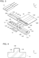
- FIG. 3 shows an assembly view of the connector assembly according to Embodiment 1.
- the sheet type conductive member 21 is disposed on the -Z direction side of the coated electric wires 31, and a connector forming component 11A is disposed on the -Z direction side of the sheet type conductive member 21.
- the connector forming component 11A is made of an insulating resin material and has a structure in which the first insulator 12 and the second insulator 13 are joined to each other by an insulator joint portion 14.
- the first insulator 12 includes a first retaining surface 12A extending along an XY plane and facing in the +Z direction, and a recess portion 12B extending in the X direction and recessed in the -Z direction is formed in the first retaining surface 12A.
- a pair of bosses 12C protruding in the +Z direction and a pair of fixing holes 12D recessed in the -Z direction.
- the second insulator 13 includes a second retaining surface 13A extending along an XY plane and facing in the +Z direction, and a protrusion portion 13B extending in the X direction and protruding in the +Z direction is formed in the second retaining surface 13A.
- a pair of bosses 13C protruding in the +Z direction and a pair of fixing holes 13D recessed in the -Z direction.
- the protrusion portion 13B corresponds to the recess portion 12B of the first insulator 12, and the pair of bosses 13C and the pair of fixing holes 13D correspond to the pair of bosses 12C and the pair of fixing holes 12D of the first insulator 12.
- the protrusion portion 13B is provided with a plurality of electric wire retaining grooves 13E each extending in a YZ plane.
- the electric wire retaining grooves 13E correspond to the conductor portions 31A of the coated electric wires 31.
- the insulator joint portion 14 joins the -Y directional side surface of the first insulator 12 to the -Y directional side surface of the second insulator 13 while the first and second insulators 12 and 13 are aligned in the X direction, and the first retaining surface 12A of the first insulator 12 and the second retaining surface 13A of the second insulator 13 are situated in the same XY plane owing to the insulator joint portion 14.
- the first sheet portion 22 of the sheet type conductive member 21 has the X-directional width equivalent to the X directional length of the first insulator 12, and a retained portion 22A corresponding to the first retaining surface 12A of the first insulator 12 is disposed at the -Y directional end portion of the first sheet portion 22, while an extension portion 22B extending in the +Y direction is disposed on the +Y direction side of the retained portion 22A.
- the retained portion 22A and the extension portion 22B are formed integrally and continuously in the Y direction.
- the retained portion 22A is provided with an H-shaped opening portion 22C extending long in the X direction.
- the opening portion 22C corresponds to the recess portion 12B of the first insulator 12, and at the +Y directional edge and the -Y directional edge of the opening portion 22C, formed separately are fold portions 22D that are folded into the recess portion 12B of the first insulator 12 when the connector assembly is assembled.
- the flexible conductors 21B each having a linear pattern extend continuously from the retained portion 22A to the extension portion 22B along the Y direction, and the -Y directional end portions 21C of the flexible conductors 21B are arranged on a surface of the fold portion 22D positioned at the +Y directional edge of the opening portion 22C.
- the second sheet portion 23 of the sheet type conductive member 21 is joined to the retained portion 22A via the sheet joint portion 24 so as to be arranged on the -X direction side of the retained portion 22A side by side and has a rectangular opening portion 23A extending long in the X direction.
- the opening portion 23A corresponds to the protrusion portion 13B of the second insulator 13.
- the sheet joint portion 24 has an opening portion 24A in its center portion.
- the second sheet portion 23 consists only of the insulating base 21A that constitutes the sheet type conductive member 21, and the flexible conductor 21B is not provided in the second sheet portion 23.
- first sheet portion 22 is provided with a plurality of through holes 22E on the periphery of the opening portion 22C
- the second sheet portion 23 is provided with a plurality of through holes 23B on the periphery of the opening portion 23A.
- the through holes 22E and 23B correspond to the pair of bosses 12C and the pair of fixing holes 12D of the first insulator 12 and the pair of bosses 13C and the pair of fixing holes 13D of the second insulator 13.
- the electric wire retaining groove 13E of the second insulator 13 is continuously formed in the -Y directional side surface, the +Y directional side surface, and the +Z directional top surface of the protrusion portion 13B in a YZ plane.
- the electric wire retaining groove 13E is used to retain the conductor portion 31A of the corresponding coated electric wire 31 when the connector assembly is assembled.
- the sheet type conductive member 21 is disposed on the connector forming component 11A as shown in FIG. 5 .
- the retained portion 22A of the first sheet portion 22 is disposed on the first retaining surface 12A of the first insulator 12, and the opening portion 22C of the retained portion 22A is situated on the +Z direction side of the recess portion 12B of the first insulator 12.
- the protrusion portion 13B of the second insulator 13 penetrates the opening portion 23A of the second sheet portion 23, and the second sheet portion 23 is disposed on the second retaining surface 13A of the second insulator 13.
- the pair of bosses 12C of the first insulator 12 penetrate the corresponding through holes 22E of the first insulator 22, and the pair of bosses 13C of the second insulator 13 penetrate the corresponding through holes 23B of the second sheet portion 23.
- the coated electric wires 31 are disposed on the -Y direction side of the second insulator 13, and the conductor portion 31A drawn from the insulating coating portion 31B of each coated electric wire 31 is inserted in the corresponding electric wire retaining groove 13E of the protrusion portion 13B of the second insulator 13, the protrusion portion 13B penetrating the opening portion 23A of the second sheet portion 23 to project in the +Z direction.
- the conductor portion 31A is inserted in the electric wire retaining groove 13E that is formed continuously from the -Y directional side surface to the +Y directional side surface via the +Z directional top surface of the protrusion portion 13B such that the conductor portion 31A crosses over the protrusion portion 13B, whereby the conductor portion 31A is retained by the protrusion portion 13B.
- the depth of the electric wire retaining groove 13E is designed to be shallower than the diameter of the conductor portion 31A; the conductor portion 31A is retained by the protrusion portion 13B in such a manner that the conductor portion 31A is not fully buried in the electric wire retaining groove 13E but partly sticks out from the side surfaces and the top surface of the protrusion portion 13B.
- the insulator joint portion 14 is cut and removed from the first and second insulators 12 and 13 as shown in FIG. 6 . It may be designed such that, by preliminarily forming a cut at a root part of the insulator joint portion 14 joined to the first and second insulators 12 and 13, for example, the insulator joint portion 14 can be easily cut and removed without use of a dedicated cutting jig or another tool.
- the insulator joint portion 14 When the insulator joint portion 14 is cut and removed, the first insulator 12 and the second insulator 13 are separated from each other, while the first sheet portion 22 and the second sheet portion 23 of the sheet type conductive member 21 are joined to each other by the sheet joint portion 24.
- the sheet joint portion 24 is folded along a folding line L extending along the Y direction perpendicular to the X direction that is the alignment direction of the coated electric wires 31 and the flexible conductors 21B, whereby the second insulator 13 together with the second sheet portion 23 and the coated electric wires 31 retained by the second insulator 13 is rotated about the folding line L by 180 degrees such that the first retaining surface 12A of the first insulator 12 and the second retaining surface 13A of the second insulator 13 are opposed to each other.
- the sheet joint portion 24 can be easily folded because the opening portion 24A is formed in the center portion of the sheet joint portion 24.
- the protrusion portion 13B of the second insulator 13 and the conductor portions 31A of the coated electric wires 31 retained by the protrusion portion 13B are accommodated in the recess portion 12B of the first insulator 12 via the opening portion 22C while folding the fold portion 22D of the retained portion 22A of the first sheet portion 22.
- end portions 21C of the plurality of flexible conductors 21B are electrically connected to the conductor portions 31A of the plurality of coated electric wires 31 on a one-by-one basis.
- the second sheet portion 23 When the second sheet portion 23 is superposed on the retained portion 22A with the first retaining surface 12A of the first insulator 12 and the second retaining surface 13A of the second insulator 13 facing each other, the second sheet portion 23 overlaps and makes contact with the retained portion 22A, and the pair of bosses 12C of the first insulator 12 shown in FIG. 3 penetrate the corresponding through holes 23B of the second sheet portion 23 and are fitted in the fixing holes 13D of the second insulator 13, while the pair of bosses 13C of the second insulator 13 penetrate the corresponding through holes 22E of the first sheet portion 22 and are fitted in the pair of fixing holes 12D of the first insulator 12.
- first insulator 12 and the second insulator 13 are fixed to each other, whereby the connector 11 is formed.
- the connector 11 is formed.
- first insulator 12, the retained portion 22A, the second sheet portion 23, and the second insulator 13 superposed on one another are glued with use of, for example, a water-resistant adhesive, a waterproof connector can be realized.
- the conductor portions 31A of the coated electric wires 31 are retained by the electric wire retaining grooves 13E of the protrusion portion 13B of the second insulator 13, whereby the conductor portions 31A of the coated electric wires 31 can be positionally aligned with the flexible conductors 21B of the sheet type conductive member 21 to establish electrical connection with high reliability while the size of the connector assembly can be reduced.
- the single connector forming component 11A having a structure in which the first insulator 12 and the second insulator 13 are joined to each other by the insulator joint portion 14, the number of components can be reduced, and after the insulator joint portion 14 is separated, the first insulator 12 and the second insulator 13 are joined to each other via the sheet j oint portion 24 of the sheet type conductive member 21, enabling easy assembly of the connector assembly by folding the sheet joint portion 24.
- the coated electric wire 31 is firmly retained in connection to the connector 11; the coated electric wire 31 can be prevented from being damaged even when an external force acts on the coated electric wire 31 or the connector 11.
- FIGS. 8 and 9 show a connector assembly according to Embodiment 2.
- This connector assembly is configured such that, in the connector assembly of Embodiment 1, a connector 41 is composed of a first insulator 42 and the second insulator 13, the first insulator 42 being used in place of the first insulator 12, and that a plurality of spring members to be described later are further incorporated in the connector 41.
- FIG. 10 shows an assembly view of the connector assembly according to Embodiment 2.
- the sheet type conductive member 21 is disposed on the -Z direction side of the coated electric wires 31, a plurality of spring members 52 joined to a carrier 51 are disposed on the -Z direction side of the sheet type conductive member 21, and a connector forming component 41A is disposed on the -Z direction side of the spring members 52.
- the sheet type conductive member 21 and the coated electric wires 31 are the same as those used in Embodiment 1.
- the connector forming component 41 is configured such that, in the connector forming component 11A used in Embodiment 1, the first insulator 42 in place of the first insulator 12 is joined to the second insulator 13 via the insulator joint portion 14, and is made of an insulating resin material.
- the first insulator 42 is obtained by forming a plurality of spring member retaining grooves 42A in the first insulator 12 used in Embodiment 1. That is, the first insulator 42 includes the first retaining surface 12A extending along an XY plane and facing in the +Z direction, and the recess portion 12B extending in the X direction and recessed in the -Z direction is formed in the first retaining surface 12A.
- the spring member retaining grooves 42A are formed on the +Y direction side of the recess portion 12B.
- the spring member retaining grooves 42A each extend from the first retaining surface 12A to the +Y directional inner surface of the recess portion 12B.
- the spring members 52 joined to the carrier 51 are made of a metal material and each include a band plate-shaped retaining portion 52A extending in the -Y direction from the carrier 51 along an XY plane and a spring portion 52B bending at the -Y directional end of the retaining portion 52A to extend in the -Z direction.
- the spring members 52 are separately disposed from the +Z direction in the spring member retaining grooves 42A of the first insulator 42 shown in FIG. 10 to be retained therein.
- the spring members 52 are retained by the first insulator 42 while being joined to the carrier 51, and the spring members 52B face an inner surface of the recess portion 12B of the first insulator 42.
- the sheet type conductive member 21 is disposed on the connector forming component 41A and the spring members 52.
- the retained portion 22A of the first sheet portion 22 is disposed on the first retaining surface 12A of the first insulator 42, and the second sheet portion 23 is disposed on the second retaining surface 13A of the second insulator 13.
- the conductor portions 31A of the coated electric wires 31 are separately inserted in the corresponding electric wire retaining grooves 13E of the protrusion portion 13B of the second insulator 13 to be retained therein, the protrusion portion 13B penetrating the opening portion 23A of the second sheet portion 23 to project in the +Z direction.
- the pair of bosses 12C of the first insulator 42 penetrate the corresponding through holes 22E of the first insulator 22, and the pair of bosses 13C of the second insulator 13 penetrate the corresponding through holes 23B of the second sheet portion 23.
- the carrier 51 joined to the spring members 52 is situated on the rear surface facing in the -Z direction of the extension portion 22B of the sheet type conductive member 21 extending from the first insulator 42 in the +Y direction.
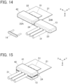
- the insulator joint portion 14 is cut and removed from the first and second insulators 42 and 13 as shown in FIGS. 13 and 14 . Accordingly, the first insulator 42 and the second insulator 13 are separated from each other, while the first sheet portion 22 and the second sheet portion 23 of the sheet type conductive member 21 are joined to each other by the sheet joint portion 24.
- the sheet joint portion 24 is folded along the folding line L extending along the Y direction, whereby the second insulator 13 together with the second sheet portion 23 and the coated electric wires 31 retained by the second insulator 13 is rotated about the folding line L by 180 degrees.
- the protrusion portion 13B of the second insulator 13 and the conductor portions 31A of the coated electric wires 31 retained by the protrusion portion 13B are accommodated in the recess portion 12B of the first insulator 42 via the opening portion 22C while folding the fold portion 22D of the retained portion 22A of the first sheet portion 22.
- the second insulator 13 is superposed on the first insulator 42 on its +Z direction side, and similarly to Embodiment 1, the first insulator 42 and the second insulator 13 are fixed to each other, whereby the connector 41 is formed.
- the spring members 52 shown in FIG. 10 are pressed from the +Z direction by the rear surface facing in the -Z direction of the retained portion 22A of the first sheet portion 22 to be thereby fixed in the connector 41.
- the carrier 51 extending from the first insulator 42 in the +Y direction along the rear surface facing in the -Z direction of the extension portion 22B of the sheet type conductive member 21 is separated from the spring members 52. It may be designed such that, by preliminarily forming cuts or grooves in the band plate-shaped retaining portions 52A of the spring members 52, for example, the carrier 51 can be easily separated out without use of a dedicated cutting jig or another tool.
- the fold portion 22D of the retained portion 22A and the conductor portion 31A of the coated electric wire 31 are held between a side surface of the protrusion portion 13B and the spring portion 52B of the spring member 52, and the end portion 21C of the flexible conductor 21B disposed on the surface of the fold portion 22D makes contact with the conductor portion 31A of the coated electric wire 31 with predetermined contact pressure owing to an elastic force of the spring portion 52B and is electrically connected to the conductor portion 31A.
- end portions 21C of the plurality of flexible conductors 21B are electrically connected to the conductor portions 31A of the plurality of coated electric wires 31 on a one-by-one basis.
- FIG. 17 shows a connector assembly according to Embodiment 3.
- the connector assembly is obtained by connecting the conductor portions 31A of the coated electric wires 31 to a sheet type conductive member 71 by means of a connector 61.
- the connector 61 includes the first insulator 12 and a second insulator 63 each made of an insulating resin material.
- the electric wires 31 and the second insulator 12 are the same as those used the connector assembly of Embodiment 1.
- FIG. 18 shows an assembly view of the connector assembly according to Embodiment 3.
- the sheet type conductive member 71 is disposed on the -Z direction side of the coated electric wires 31, and a connector forming component 61A is disposed on the -Z direction side of the sheet type conductive member 71.
- the connector forming component 61A is configured such that, in the connector forming component 11A used in Embodiment 1, the second insulator 63 in place of the second insulator 13 is joined to the first insulator 12 via a pair of insulator joint portions 64, and is made of an insulating resin material.
- the second insulator 63 is obtained by forming a plurality of electric wire accommodation grooves 63A in the second insulator 13 used in Embodiment 1. That is, the second insulator 63 includes the second retaining surface 13A extending along an XY plane and facing in the +Z direction, and the protrusion portion 13B extending in the X direction and protruding in the +Z direction is formed in the second retaining surface 13A.
- the protrusion portion 13B is provided with the electric wire retaining grooves 13E each extending in a YZ plane, and the electric wire accommodation grooves 63A each extending from the second retaining surface 13A in the -Z direction are formed on the +Y directional side surface of the second insulator 63 so as to correspond to the electric wire retaining grooves 13E.
- the second insulator 63 is disposed at the same X directional position as that of the first insulator 12 and arranged on the +Y direction side of the first insulator 12 side by side, and the +X directional side surface and the -X directional side surface of the first insulator 12 are separately joined to the +X directional side surface and the -X directional side surface of the second insulator 63 by the pair of insulator joint portions 64.
- the first retaining surface 12A of the first insulator 12 and the second retaining surface 13A of the second insulator 63 are situated in the same XY plane owing to the pair of insulator joint portions 64.
- the sheet type conductive member 71 is obtained by, in the sheet type conductive member 21 used in Embodiment 1, disposing the first sheet portion 22 such that the extension portion 22B is situated on the -Y direction side of the retained portion 22A, and joining the first sheet portion 22 to the second sheet portion 23 via a sheet joint portion 74 such that the second sheet portion 23 is arranged on the +Y direction side of the retained portion 22A side by side. That is, the first sheet portion 22 and the second sheet portion 23 are disposed at the same X directional position.
- the flexible conductors 21B extend in the -Y direction from the H-shaped opening portion 22C in the retained portion 22A of the first sheet portion 22, and the end portions 21C of the flexible conductors 21B are disposed at the fold portion 22D formed at the -Y directional edge of the opening portion 22C.
- the second sheet portion 23 is provided with the rectangular opening portion 23A extending long in the X direction.
- the sheet joint portion 74 has an opening portion 74A in its center portion.
- the sheet type conductive member 71 is disposed on the connector forming component 61A as shown in FIG. 19 .
- the retained portion 22A of the first sheet portion 22 is disposed on the first retaining surface 12A of the first insulator 12
- the second sheet portion 23 is disposed on the second retaining surface 13A of the second insulator 63.
- the protrusion portion 13B of the second insulator 63 penetrates the opening portion 23A of the second sheet portion 23.
- the pair of bosses 12C of the first insulator 12 penetrate the corresponding through holes 22E of the first insulator 22, and the pair of bosses 13C of the second insulator 63 penetrate the corresponding through holes 23B of the second sheet portion 23.
- the coated electric wires 31 are disposed on the +Y direction side of the second insulator 63, and the conductor portion 31A drawn in the -Y direction from the insulating coating portion 31B of each coated electric wire 31 is inserted in the corresponding electric wire retaining groove 13E of the protrusion portion 13B of the second insulator 63.
- the conductor portion 31A drawn in the -Y direction from the coated electric wire 31 is bent in the +Z direction and accommodated in the corresponding electric wire accommodation groove 63A of the second insulator 63 shown in FIG. 18 , and the conductor portion 31A is further bent in the -Y direction at the +Y directional end portion of the second sheet portion 23 and inserted in the corresponding electric wire retaining groove 13E of the protrusion portion 13B.
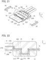
- the pair of insulator joint portions 64 are cut and removed from the first insulator 12 and the second insulator 63 as shown in FIG. 21 . Accordingly, the first insulator 12 and the second insulator 63 are separated from each other, while the first sheet portion 22 and the second sheet portion 23 of the sheet type conductive member 71 are joined to each other by the sheet joint portion 74.
- the sheet joint portion 74 is folded along the folding line L extending along the X direction that is the alignment direction of the coated electric wires 31 and the flexible conductors 21B, whereby the second insulator 63 together with the second sheet portion 23 and the coated electric wires 31 retained by the second insulator 63 is rotated about the folding line L by 180 degrees.
- the sheet joint portion 74 can be easily folded because the opening portion 74A is formed in the center portion of the sheet joint portion 74.
- the protrusion portion 13B of the second insulator 63 and the conductor portions 31A of the coated electric wires 31 retained by the protrusion portion 13B are accommodated in the recess portion 12B of the first insulator 12 via the opening portion 22C while folding the fold portion 22D of the retained portion 22A of the first sheet portion 22.
- the first insulator 12 and the second insulator 63 are fixed to each other, whereby the connector 61 is formed.
- the fold portion 22D of the retained potion 22A and the conductor portion 31A of the coated electric wire 31 are held between the side surface of the protrusion portion 13B and the inner side surface of the recess portion 12B as shown in FIG. 22 .
- the end portion 21C of the flexible conductor 21B is disposed on the surface of the fold portion 22D of the retained portion 22A, the end portion 21C of the flexible conductor 21B makes contact with the conductor portion 31A of the coated electric wire 31 with predetermined contact pressure and is electrically connected to the conductor portion 31A.
- end portions 21C of the plurality of flexible conductors 21B are electrically connected to the conductor portions 31A of the plurality of coated electric wires 31 on a one-by-one basis.
- the extension portion 22B of the first sheet portion 22 of the sheet type conductive member 71 and the coated electric wire 31 both extend in the -Y direction from the connector 61 in FIG. 22 , since part of the conductor portion 31A of the coated electric wire 31 is accommodated in the electric wire accommodation groove 63A formed in the side surface of the second insulator 63 and extending in the Z direction, the insulating coating portion 31B of the coated electric wire 31 is situated on the surface facing in the +Z direction of the extension portion 22B. In other words, the insulating coating portion 31B of the coated electric wire 31 and the extension portion 22B of the sheet type conductive member 71 can extend in the -Y direction without interfering with each other in the Z direction.
- the flexible conductors 21B of the sheet type conductive member 71 can be electrically connected to the conductor portions 31A of the coated electric wires 31 with high reliability.
- Embodiment 2 it is also possible to improve reliability in electric connection between the flexible conductors 21B of the sheet type conductive member 71 and the conductor portions 31A of the coated electric wires 31 by incorporation of the spring members 52 in the connector 61 in Embodiment 3.
- coated electric wire 31 is used as an electric wire to be connected to the flexible conductor 21B of the sheet type conductive member 21, 71 in Embodiments 1 to 3 above, an electric wire formed of only the conductor portion 31A whose outer periphery is not covered with the insulating coating portion 31B can also be connected to the flexible conductor 21B of the sheet type conductive member 21, 71.
Landscapes
- Engineering & Computer Science (AREA)
- Manufacturing & Machinery (AREA)
- Coupling Device And Connection With Printed Circuit (AREA)
Claims (17)
- Ensemble connecteur pour raccorder une partie conductrice (31A) d'un fil électrique (31) à un conducteur souple (21B) exposé sur une surface d'un élément conducteur de type feuille (21, 71), l'ensemble connecteur comprenant :un élément conducteur de type feuille (21, 71) comportant un conducteur souple (21B) exposé sur une de ses surfaces ; un fil électrique (31) comportant une partie conductrice (31A) ; etun connecteur (11, 41, 61) pour raccorder la partie conductrice au conducteur souple,dans lequel le connecteur comporte un premier isolateur (12, 42) et un second isolateur (13, 63), le premier isolateur comportant une première surface de retenue (12A) et une partie évidée (12B) formée dans la première surface de retenue, et le second isolateur comportant une seconde surface de retenue (13A) opposée à la première surface de retenue et une partie saillante (13B) formée sur la seconde surface de retenue pour faire saillie à partir de celle-ci et correspondant à la partie évidée,l'élément conducteur de type feuille comporte une première partie de feuille (22) et une seconde partie de feuille (23), la première partie de feuille comportant une partie retenue (22A) disposée sur la première surface de retenue, et la seconde partie de feuille étant disposée sur la seconde surface de retenue,le conducteur souple est exposé sur une surface de la partie retenue de la première partie de la feuille, et une partie d'extrémité du conducteur souple est disposée dans la partie évidée,la partie saillante et la partie conductrice du fil électrique sont logées dans la partie évidée dans un état où la partie conductrice du fil électrique est disposée le long d'une surface de la partie saillante, etle premier isolateur et le second isolateur sont fixés l'un à l'autre de telle sorte que des parties superposées de la partie retenue de la première partie de feuille et de la seconde partie de feuille sont maintenues entre la première surface de retenue et la seconde surface de retenue, de telle sorte que le conducteur souple (21B) entre en contact avec la partie conductrice (31A) du fil électrique dans la partie évidée et est relié électriquement à celle-ci.
- Ensemble connecteur selon la revendication 1,dans lequel la première partie de feuille (22) comporte une partie d'extension (22B) s'étendant à partir de la partie retenue vers un extérieur du connecteur le long d'une direction prédéterminée,la partie de retenue (22A) comporte une partie de pli (22D) disposée dans la partie évidée,le conducteur souple (21B) est disposé en continu de la partie retenue à la partie d'extension, etla partie d'extrémité du conducteur souple est disposée sur la partie de pli.
- Ensemble connecteur selon la revendication 1 ou 2,dans lequel la première partie de feuille (22) comporte une base isolante (21A) de type feuille et le conducteur souple (21B) disposé sur la base isolante de manière à former un motif prédéterminé, etla seconde partie de feuille (23) est constituée uniquement d'une base isolante (21A) de type feuille.
- Ensemble connecteur selon l'une quelconque des revendications 1 à 3, dans lequel la seconde partie de feuille (23) possède une partie d'ouverture (23A) et est disposée sur la seconde surface de retenue (13A) avec la partie saillante insérée dans la partie d'ouverture.
- Ensemble connecteur selon l'une quelconque des revendications 1 à 4, dans lequel l'élément conducteur de type feuille (21, 71) comporte une partie de joint de feuille (24, 74) reliant la première partie de feuille (22) et la seconde partie de feuille (23) l'une à l'autre, et la partie de joint de feuille dépasse vers un extérieur du connecteur.
- Ensemble connecteur selon l'une quelconque des revendications 1 à 5, dans lequel la partie d'extrémité du conducteur souple (21B) et la partie conductrice (31A) du fil électrique (31) sont maintenues entre une surface latérale de la partie saillante (13B) et une surface latérale intérieure de la partie évidée (12B) pour ainsi entrer en contact l'une avec l'autre et être reliées électriquement l'une à l'autre.
- Ensemble connecteur selon l'une quelconque des revendications 1 à 6, dans lequel le connecteur (41) comporte un élément ressort (52) qui presse la partie d'extrémité du conducteur souple et la partie conductrice du fil électrique l'une contre l'autre dans la partie évidée.
- Ensemble connecteur selon l'une quelconque des revendications 1 à 7, dans lequel la partie conductrice (31A) du fil électrique est disposée le long des deux surfaces latérales et d'une surface supérieure de la partie saillante (13B) de manière à traverser la partie saillante.
- Ensemble connecteur selon la revendication 8,dans lequel la partie saillante (13B) comporte une rainure de retenue de fil électrique (13E) formée en continu sur les deux surfaces latérales et la surface supérieure, etla partie conductrice (31A) du fil électrique est logée dans la partie évidée (12B) tout en étant insérée dans la rainure de retenue de fil électrique.
- Ensemble connecteur selon l'une quelconque des revendications 1 à 9, dans lequel un bossage (12C, 13C) formé sur l'une de la première surface de retenue et de la seconde surface de retenue est inséré dans un trou de fixation (12D, 13D) formé dans une autre de la première surface de retenue et de la seconde surface de retenue, moyennant quoi le premier isolateur (12, 42) et le second isolateur (13, 63) sont fixés l'un à l'autre.
- Ensemble connecteur selon l'une quelconque des revendications 1 à 10,dans lequel la partie évidée (12B) s'étend dans une direction prédéterminée le long de la première surface de retenue (12A),la partie saillante (13B) s'étend dans la direction prédéterminée le long de la seconde surface de retenue (13A),l'élément conducteur de type feuille (21,71) comporte une pluralité des conducteurs souples (2IB) disposés sur la première partie de feuille et alignés dans la direction prédéterminée, etla pluralité des conducteurs souples (21B) est reliée électriquement aux parties conductrices (31A) d'une pluralité des fils électriques alignés dans la direction prédéterminée, un par un.
- Ensemble connecteur selon la revendication 11, dans lequel la pluralité des conducteurs souples (21B) et la pluralité des fils électriques (31) s'étendent vers un extérieur du connecteur (61) le long d'une même direction.
- Ensemble connecteur selon la revendication 11, dans lequel la pluralité des conducteurs souples (21B) et la pluralité des fils électriques (31) s'étendent vers un extérieur du connecteur (11, 41) dans des directions opposées l'une à l'autre.
- Procédé de raccordement permettant de raccorder une partie conductrice (31A) d'un fil électrique (31) à un conducteur souple (21B) exposé sur une surface d'un élément conducteur de type feuille (21, 71), le procédé de raccordement comprenant :dans un composant formant connecteur (11A, 41A, 61A) dans lequel un premier isolateur (12, 42) et un second isolateur (13, 63) sont reliés l'un à l'autre par une partie de joint d'isolateurs (14, 64) de sorte qu'une première surface de retenue (12A) du premier isolateur et une seconde surface de retenue (13A) du second isolateur soient situées dans un même plan, la disposition d'une partie retenue (22A) d'une première partie de feuille (22) de l'élément conducteur de type feuille sur laquelle le conducteur souple est exposé sur la première surface de retenue, et d'une seconde partie de feuille (23) de l'élément conducteur de type feuille reliée à la partie retenue par l'intermédiaire d'une partie de joint de feuille (24, 74) sur la seconde surface de retenue,la disposition de la partie conductrice (31A) du fil électrique le long d'une surface d'une partie saillante (13B) formée sur la seconde surface de retenue pour faire saillie à partir de celle-ci,la découpe et le retrait de la partie de joint d'isolateurs (14, 64) de l'élément formant connecteur (11A, 41A, 61A),le pliage de la partie de joint de feuille (24, 74) pour ainsi loger la partie saillante (13B) et la partie conductrice (31A) du fil électrique avec une partie d'extrémité du conducteur souple (21B) exposée sur la partie retenue de la première partie de feuille dans une partie évidée (12B) formée dans la première surface de retenue du premier isolateur, la première surface de retenue et la seconde surface de retenue étant opposées l'une à l'autre, etla fixation du premier isolateur et du second isolateur l'un à l'autre tandis que la partie retenue de la première partie de feuille et de la seconde partie de feuille sont maintenues entre la première surface de retenue et la seconde surface de retenue, moyennant quoi le conducteur souple (21B) entre en contact avec la partie conductrice (31A) du fil électrique dans la partie évidée et est relié électriquement à celle-ci.
- Procédé de raccordement selon la revendication 14,dans lequel la partie évidée (12B) s'étend dans une direction prédéterminée le long de la première surface de retenue (12A),la partie saillante (13B) s'étend dans la direction prédéterminée le long de la seconde surface de retenue (13A),l'élément conducteur de type feuille (21,71) comporte une pluralité de conducteurs souples (2IB) disposés sur la première partie de feuille et alignés dans la direction prédéterminée, etla pluralité des conducteurs souples (21B) est reliée électriquement aux parties conductrices (31A) d'une pluralité des fils électriques alignés dans la direction prédéterminée, un par un.
- Procédé de raccordement selon la revendication 15,dans lequel la partie de joint d'isolateurs (14) relie le premier isolateur (12) et le second isolateur (13) dans un état où le premier isolateur et le second isolateur sont alignés côte à côte dans la direction prédéterminée,la partie de joint de feuille (24) relie la première partie de feuille (22) et la seconde partie de feuille (23) dans un état où la première partie de feuille et la seconde partie de feuille sont alignées côte à côte dans la direction prédéterminée, etaprès que la partie de joint d'isolateurs (14) a été découpée et retirée du composant formant connecteur (11A, 41A), la partie de joint de feuille (24) est pliée le long d'une ligne de pliage (L) s'étendant dans une direction perpendiculaire à la direction prédéterminée.
- Procédé de raccordement selon la revendication 15,dans lequel la partie de joint d'isolateurs (64) relie le premier isolateur (42) et le second isolateur (63) dans un état où le premier isolateur et le second isolateur sont alignés côte à côte dans une direction perpendiculaire à la direction prédéterminée,la partie de joint de feuille (74) relie la première partie de feuille (22) et la seconde partie de feuille (23) dans un état où la première partie de feuille et la seconde partie de feuille sont alignées côte à côte dans la direction perpendiculaire à la direction prédéterminée, et après que la partie de joint d'isolateurs (64) a été découpée et retirée du composant formant connecteur (61A), la partie de joint de feuille (74) est pliée le long d'une ligne de pliage (L) s'étendant dans la direction prédéterminée.
Applications Claiming Priority (1)
| Application Number | Priority Date | Filing Date | Title |
|---|---|---|---|
| JP2022191168A JP2024078683A (ja) | 2022-11-30 | 2022-11-30 | コネクタ組立体および接続方法 |
Publications (2)
| Publication Number | Publication Date |
|---|---|
| EP4379963A1 EP4379963A1 (fr) | 2024-06-05 |
| EP4379963B1 true EP4379963B1 (fr) | 2025-04-30 |
Family
ID=88287316
Family Applications (1)
| Application Number | Title | Priority Date | Filing Date |
|---|---|---|---|
| EP23201604.8A Active EP4379963B1 (fr) | 2022-11-30 | 2023-10-04 | Ensemble connecteur et procédé de connexion |
Country Status (4)
| Country | Link |
|---|---|
| US (1) | US12567689B2 (fr) |
| EP (1) | EP4379963B1 (fr) |
| JP (1) | JP2024078683A (fr) |
| CN (1) | CN118117364A (fr) |
Families Citing this family (1)
| Publication number | Priority date | Publication date | Assignee | Title |
|---|---|---|---|---|
| JP2024079143A (ja) * | 2022-11-30 | 2024-06-11 | 日本航空電子工業株式会社 | コネクタ組立体および接続方法 |
Citations (1)
| Publication number | Priority date | Publication date | Assignee | Title |
|---|---|---|---|---|
| DE202021002195U1 (de) * | 2021-06-18 | 2022-01-10 | Printlec UG (haftungsbeschränkt) | Ein Steckverbindersystem, das die Übertragung von elektrischen Strömen oder Signalen zwischen verschiedenen leitfähigen Medien unterstützt |
Family Cites Families (40)
| Publication number | Priority date | Publication date | Assignee | Title |
|---|---|---|---|---|
| JPS5851581U (ja) * | 1981-10-03 | 1983-04-07 | ソニー株式会社 | プリント基板用コネクタ |
| US4647125A (en) * | 1985-07-22 | 1987-03-03 | Rogers Corporation | Solderless connector technique |
| US4859204A (en) * | 1988-05-13 | 1989-08-22 | Amp Incorporated | Method of staking a wave crimp for flat power cable termination |
| US5057032A (en) * | 1990-06-04 | 1991-10-15 | Amp Incorporated | Board edge connector |
| US5163836A (en) * | 1991-03-11 | 1992-11-17 | Apple Computer, Inc. | Integrated connector module with conductive elastomeric contacts |
| JP2874405B2 (ja) * | 1991-09-10 | 1999-03-24 | 住友電装株式会社 | フラットケーブルの接続方法 |
| US5356308A (en) * | 1991-10-31 | 1994-10-18 | Sumitomo Wiring Systems, Ltd. | Connector assembly for a flexible wiring plate |
| JP2827635B2 (ja) * | 1991-10-31 | 1998-11-25 | 住友電装株式会社 | フレキシブル配線板用コネクタ構造 |
| US6447305B1 (en) * | 1996-05-14 | 2002-09-10 | Miraco, Inc. | Circuit to printed circuit board stored energy connector |
| US5730619A (en) * | 1996-07-01 | 1998-03-24 | General Motors Corporation | Externally locked connector |
| US6247951B1 (en) * | 1998-05-29 | 2001-06-19 | Delphi Technologies, Inc. | Flexible circuit connector |
| US6302704B1 (en) * | 1999-04-22 | 2001-10-16 | Ford Global Tech. | Method and apparatus for selectively connecting flexible circuits |
| JP3692268B2 (ja) * | 1999-12-15 | 2005-09-07 | 矢崎総業株式会社 | フラット回路体用のコネクタ及び該コネクタへのフラット回路体の接続構造 |
| DE10050797A1 (de) | 2000-10-13 | 2002-04-25 | Daimler Chrysler Ag | Vorrichtung und Verfahren zum Verbinden von Folienkabelenden mit anisotropen Leitklebern |
| US6520810B1 (en) * | 2001-10-24 | 2003-02-18 | Molex Incorporated | Connector system for interconnection with flat flexible circuitry |
| US6880241B2 (en) * | 2002-09-30 | 2005-04-19 | General Electric Company A New York Corporation | Method for connecting coaxial cables to a printed circuit board |
| DE10250924A1 (de) * | 2002-10-31 | 2004-05-19 | Fci | Inline-Klemmverbinder für Flex-Flachbandkabel |
| US7201606B2 (en) * | 2003-05-30 | 2007-04-10 | 3M Innovative Properties Company | Wire connection structure and connector |
| US6974344B2 (en) * | 2003-08-12 | 2005-12-13 | Molex Incorporated | Board mounted electrical connector assembly |
| US7238032B2 (en) * | 2003-10-29 | 2007-07-03 | Fci | Connector arrangement between a flat flex cable and a component |
| JP2005294106A (ja) * | 2004-04-01 | 2005-10-20 | Three M Innovative Properties Co | コネクタ及びその結線方法 |
| DE102004050687B4 (de) * | 2004-10-18 | 2019-01-31 | Continental Automotive Gmbh | Kontaktierungsanordnung für eine flexible Leiterplatte und deren Verwendung |
| JP2006294386A (ja) * | 2005-04-08 | 2006-10-26 | Tyco Electronics Amp Kk | 電気コネクタ、ワイヤハーネス及びワイヤハーネスの配置方法 |
| JP2007214087A (ja) | 2006-02-13 | 2007-08-23 | Fujikura Ltd | コネクタ |
| JP4818833B2 (ja) * | 2006-06-30 | 2011-11-16 | 日本圧着端子製造株式会社 | 平形柔軟ケーブルのハーネス |
| JP4795179B2 (ja) * | 2006-09-11 | 2011-10-19 | モレックス インコーポレイテド | コネクタ |
| US7892028B2 (en) * | 2009-01-20 | 2011-02-22 | Hon Hai Precision Ind. Co., Ltd. | Cable connector assembly |
| CN101801155A (zh) * | 2009-02-09 | 2010-08-11 | 富士康(昆山)电脑接插件有限公司 | 柔性印刷电路板及安装有柔性印刷电路板的电连接器 |
| WO2010129568A1 (fr) | 2009-05-04 | 2010-11-11 | Advanced Bionics, Llc | Système de connecteur à multiples contacts |
| TWI401847B (zh) * | 2009-09-10 | 2013-07-11 | Hon Hai Prec Ind Co Ltd | 線纜連接器組合 |
| JP5570016B2 (ja) * | 2009-11-26 | 2014-08-13 | 日本圧着端子製造株式会社 | フラットケーブル用コネクタ、ハーネス、及びハーネスの製造方法 |
| JP5600523B2 (ja) * | 2010-08-27 | 2014-10-01 | 矢崎総業株式会社 | コネクタ構造 |
| US8622753B2 (en) * | 2010-12-09 | 2014-01-07 | Basic Electronics, Inc. | Pin connector assembly |
| JP2012169243A (ja) * | 2011-01-28 | 2012-09-06 | Tyco Electronics Japan Kk | フレキシブルケーブルコネクタ |
| JP7232070B2 (ja) * | 2019-02-12 | 2023-03-02 | 日本航空電子工業株式会社 | コネクタ組立体、コネクタ組立体のコネクタ対、及び、コネクタ組立体の製造方法 |
| JP7196035B2 (ja) * | 2019-08-23 | 2022-12-26 | 日本航空電子工業株式会社 | コネクタおよび接続方法 |
| US10591114B1 (en) * | 2019-09-19 | 2020-03-17 | Elemental LED, Inc. | Connectors for linear lighting |
| US11411334B2 (en) * | 2020-01-03 | 2022-08-09 | Aptiv Technologies Limited | Electrical connector for connecting to flat-wire conductors of a flexible printed circuit |
| JP7748880B2 (ja) * | 2022-01-12 | 2025-10-03 | 日本航空電子工業株式会社 | コネクタ |
| JP2024039795A (ja) * | 2022-09-12 | 2024-03-25 | 日本航空電子工業株式会社 | コネクタ |
-
2022
- 2022-11-30 JP JP2022191168A patent/JP2024078683A/ja active Pending
-
2023
- 2023-09-15 US US18/467,950 patent/US12567689B2/en active Active
- 2023-09-20 CN CN202311221704.7A patent/CN118117364A/zh active Pending
- 2023-10-04 EP EP23201604.8A patent/EP4379963B1/fr active Active
Patent Citations (1)
| Publication number | Priority date | Publication date | Assignee | Title |
|---|---|---|---|---|
| DE202021002195U1 (de) * | 2021-06-18 | 2022-01-10 | Printlec UG (haftungsbeschränkt) | Ein Steckverbindersystem, das die Übertragung von elektrischen Strömen oder Signalen zwischen verschiedenen leitfähigen Medien unterstützt |
Also Published As
| Publication number | Publication date |
|---|---|
| JP2024078683A (ja) | 2024-06-11 |
| CN118117364A (zh) | 2024-05-31 |
| EP4379963A1 (fr) | 2024-06-05 |
| US20240178595A1 (en) | 2024-05-30 |
| US12567689B2 (en) | 2026-03-03 |
Similar Documents
| Publication | Publication Date | Title |
|---|---|---|
| CN103050793B (zh) | 同轴连接器装置 | |
| US7503797B2 (en) | Plug-in connector with strain relief | |
| US10630004B2 (en) | Connection assisting member and circuit board assembly | |
| US9673546B2 (en) | Cable holding member, electrical connection device, connector device, flat cable | |
| JP2002203645A (ja) | ケーブルコネクタ | |
| US6068505A (en) | Electrical contact for flexible flat cable | |
| JPH05826B2 (fr) | ||
| EP3783742A1 (fr) | Connecteur et procédé de connexion | |
| US12424774B2 (en) | Connector | |
| JP2006054102A (ja) | コネクタ及びケーブル保持部材 | |
| EP4379963B1 (fr) | Ensemble connecteur et procédé de connexion | |
| JP2006054101A (ja) | コネクタ及びケーブル保持部材 | |
| KR20060135054A (ko) | 커넥터 및 그 결선 방법 | |
| US12230907B2 (en) | Electrical connector for connecting an electric wire to a flat flexible conductor and an electrical connector assembly therefor | |
| EP3696918B1 (fr) | Procédé de connexion, structure de connexion et borne de connexion | |
| JP2009037748A (ja) | ケーブルコネクタ及びケーブル接続方法 | |
| KR101876088B1 (ko) | 섬유용 전기 커넥터 | |
| CN111952815B (zh) | 连接方法、连接结构、触头和连接器 | |
| EP3683895B1 (fr) | Connecteur, ensemble carte de circuits et structure de connexion | |
| US20200235536A1 (en) | Coated conductive wire connecting method, coated conductive wire connecting structure and coated conductive wire connecting member | |
| JP7011503B2 (ja) | 接続補助部材および配線板組立体 | |
| EP4343974B1 (fr) | Connecteur | |
| EP4346013B1 (fr) | Connecteur, ensemble connecteur et procédé de connexion | |
| JP3679295B2 (ja) | フラット回路体の分岐接続構造 | |
| JP4807796B2 (ja) | ケーブルコネクタ及びケーブル接続方法 |
Legal Events
| Date | Code | Title | Description |
|---|---|---|---|
| PUAI | Public reference made under article 153(3) epc to a published international application that has entered the european phase |
Free format text: ORIGINAL CODE: 0009012 |
|
| STAA | Information on the status of an ep patent application or granted ep patent |
Free format text: STATUS: REQUEST FOR EXAMINATION WAS MADE |
|
| 17P | Request for examination filed |
Effective date: 20231004 |
|
| AK | Designated contracting states |
Kind code of ref document: A1 Designated state(s): AL AT BE BG CH CY CZ DE DK EE ES FI FR GB GR HR HU IE IS IT LI LT LU LV MC ME MK MT NL NO PL PT RO RS SE SI SK SM TR |
|
| RBV | Designated contracting states (corrected) |
Designated state(s): AL AT BE BG CH CY CZ DE DK EE ES FI FR GB GR HR HU IE IS IT LI LT LU LV MC ME MK MT NL NO PL PT RO RS SE SI SK SM TR |
|
| RAP3 | Party data changed (applicant data changed or rights of an application transferred) |
Owner name: JAPAN AVIATION ELECTRONICS INDUSTRY, LIMITED |
|
| GRAP | Despatch of communication of intention to grant a patent |
Free format text: ORIGINAL CODE: EPIDOSNIGR1 |
|
| STAA | Information on the status of an ep patent application or granted ep patent |
Free format text: STATUS: GRANT OF PATENT IS INTENDED |
|
| GRAJ | Information related to disapproval of communication of intention to grant by the applicant or resumption of examination proceedings by the epo deleted |
Free format text: ORIGINAL CODE: EPIDOSDIGR1 |
|
| STAA | Information on the status of an ep patent application or granted ep patent |
Free format text: STATUS: REQUEST FOR EXAMINATION WAS MADE |
|
| INTG | Intention to grant announced |
Effective date: 20241203 |
|
| INTC | Intention to grant announced (deleted) | ||
| GRAP | Despatch of communication of intention to grant a patent |
Free format text: ORIGINAL CODE: EPIDOSNIGR1 |
|
| STAA | Information on the status of an ep patent application or granted ep patent |
Free format text: STATUS: GRANT OF PATENT IS INTENDED |
|
| INTG | Intention to grant announced |
Effective date: 20250207 |
|
| GRAS | Grant fee paid |
Free format text: ORIGINAL CODE: EPIDOSNIGR3 |
|
| GRAA | (expected) grant |
Free format text: ORIGINAL CODE: 0009210 |
|
| STAA | Information on the status of an ep patent application or granted ep patent |
Free format text: STATUS: THE PATENT HAS BEEN GRANTED |
|
| AK | Designated contracting states |
Kind code of ref document: B1 Designated state(s): AL AT BE BG CH CY CZ DE DK EE ES FI FR GB GR HR HU IE IS IT LI LT LU LV MC ME MK MT NL NO PL PT RO RS SE SI SK SM TR |
|
| REG | Reference to a national code |
Ref country code: CH Ref legal event code: EP Ref country code: GB Ref legal event code: FG4D |
|
| REG | Reference to a national code |
Ref country code: IE Ref legal event code: FG4D |
|
| REG | Reference to a national code |
Ref country code: DE Ref legal event code: R096 Ref document number: 602023003192 Country of ref document: DE |
|
| REG | Reference to a national code |
Ref country code: NL Ref legal event code: MP Effective date: 20250430 |
|
| REG | Reference to a national code |
Ref country code: AT Ref legal event code: MK05 Ref document number: 1790985 Country of ref document: AT Kind code of ref document: T Effective date: 20250430 |
|
| PG25 | Lapsed in a contracting state [announced via postgrant information from national office to epo] |
Ref country code: FI Free format text: LAPSE BECAUSE OF FAILURE TO SUBMIT A TRANSLATION OF THE DESCRIPTION OR TO PAY THE FEE WITHIN THE PRESCRIBED TIME-LIMIT Effective date: 20250430 Ref country code: PT Free format text: LAPSE BECAUSE OF FAILURE TO SUBMIT A TRANSLATION OF THE DESCRIPTION OR TO PAY THE FEE WITHIN THE PRESCRIBED TIME-LIMIT Effective date: 20250901 Ref country code: ES Free format text: LAPSE BECAUSE OF FAILURE TO SUBMIT A TRANSLATION OF THE DESCRIPTION OR TO PAY THE FEE WITHIN THE PRESCRIBED TIME-LIMIT Effective date: 20250430 |
|
| REG | Reference to a national code |
Ref country code: LT Ref legal event code: MG9D |
|
| PG25 | Lapsed in a contracting state [announced via postgrant information from national office to epo] |
Ref country code: NO Free format text: LAPSE BECAUSE OF FAILURE TO SUBMIT A TRANSLATION OF THE DESCRIPTION OR TO PAY THE FEE WITHIN THE PRESCRIBED TIME-LIMIT Effective date: 20250730 Ref country code: GR Free format text: LAPSE BECAUSE OF FAILURE TO SUBMIT A TRANSLATION OF THE DESCRIPTION OR TO PAY THE FEE WITHIN THE PRESCRIBED TIME-LIMIT Effective date: 20250731 |
|
| PG25 | Lapsed in a contracting state [announced via postgrant information from national office to epo] |
Ref country code: NL Free format text: LAPSE BECAUSE OF FAILURE TO SUBMIT A TRANSLATION OF THE DESCRIPTION OR TO PAY THE FEE WITHIN THE PRESCRIBED TIME-LIMIT Effective date: 20250430 Ref country code: PL Free format text: LAPSE BECAUSE OF FAILURE TO SUBMIT A TRANSLATION OF THE DESCRIPTION OR TO PAY THE FEE WITHIN THE PRESCRIBED TIME-LIMIT Effective date: 20250430 |
|
| PG25 | Lapsed in a contracting state [announced via postgrant information from national office to epo] |
Ref country code: BG Free format text: LAPSE BECAUSE OF FAILURE TO SUBMIT A TRANSLATION OF THE DESCRIPTION OR TO PAY THE FEE WITHIN THE PRESCRIBED TIME-LIMIT Effective date: 20250430 |
|
| PG25 | Lapsed in a contracting state [announced via postgrant information from national office to epo] |
Ref country code: HR Free format text: LAPSE BECAUSE OF FAILURE TO SUBMIT A TRANSLATION OF THE DESCRIPTION OR TO PAY THE FEE WITHIN THE PRESCRIBED TIME-LIMIT Effective date: 20250430 |
|
| PG25 | Lapsed in a contracting state [announced via postgrant information from national office to epo] |
Ref country code: AT Free format text: LAPSE BECAUSE OF FAILURE TO SUBMIT A TRANSLATION OF THE DESCRIPTION OR TO PAY THE FEE WITHIN THE PRESCRIBED TIME-LIMIT Effective date: 20250430 |
|
| PG25 | Lapsed in a contracting state [announced via postgrant information from national office to epo] |
Ref country code: RS Free format text: LAPSE BECAUSE OF FAILURE TO SUBMIT A TRANSLATION OF THE DESCRIPTION OR TO PAY THE FEE WITHIN THE PRESCRIBED TIME-LIMIT Effective date: 20250731 |
|
| PG25 | Lapsed in a contracting state [announced via postgrant information from national office to epo] |
Ref country code: IS Free format text: LAPSE BECAUSE OF FAILURE TO SUBMIT A TRANSLATION OF THE DESCRIPTION OR TO PAY THE FEE WITHIN THE PRESCRIBED TIME-LIMIT Effective date: 20250830 |
|
| PG25 | Lapsed in a contracting state [announced via postgrant information from national office to epo] |
Ref country code: LV Free format text: LAPSE BECAUSE OF FAILURE TO SUBMIT A TRANSLATION OF THE DESCRIPTION OR TO PAY THE FEE WITHIN THE PRESCRIBED TIME-LIMIT Effective date: 20250430 |
|
| PGFP | Annual fee paid to national office [announced via postgrant information from national office to epo] |
Ref country code: DE Payment date: 20251015 Year of fee payment: 3 |
|
| PG25 | Lapsed in a contracting state [announced via postgrant information from national office to epo] |
Ref country code: DK Free format text: LAPSE BECAUSE OF FAILURE TO SUBMIT A TRANSLATION OF THE DESCRIPTION OR TO PAY THE FEE WITHIN THE PRESCRIBED TIME-LIMIT Effective date: 20250430 Ref country code: SM Free format text: LAPSE BECAUSE OF FAILURE TO SUBMIT A TRANSLATION OF THE DESCRIPTION OR TO PAY THE FEE WITHIN THE PRESCRIBED TIME-LIMIT Effective date: 20250430 |
|
| PGFP | Annual fee paid to national office [announced via postgrant information from national office to epo] |
Ref country code: FR Payment date: 20251030 Year of fee payment: 3 |
|
| PG25 | Lapsed in a contracting state [announced via postgrant information from national office to epo] |
Ref country code: CZ Free format text: LAPSE BECAUSE OF FAILURE TO SUBMIT A TRANSLATION OF THE DESCRIPTION OR TO PAY THE FEE WITHIN THE PRESCRIBED TIME-LIMIT Effective date: 20250430 |
|
| PG25 | Lapsed in a contracting state [announced via postgrant information from national office to epo] |
Ref country code: EE Free format text: LAPSE BECAUSE OF FAILURE TO SUBMIT A TRANSLATION OF THE DESCRIPTION OR TO PAY THE FEE WITHIN THE PRESCRIBED TIME-LIMIT Effective date: 20250430 |
|
| PG25 | Lapsed in a contracting state [announced via postgrant information from national office to epo] |
Ref country code: SK Free format text: LAPSE BECAUSE OF FAILURE TO SUBMIT A TRANSLATION OF THE DESCRIPTION OR TO PAY THE FEE WITHIN THE PRESCRIBED TIME-LIMIT Effective date: 20250430 |
|
| PG25 | Lapsed in a contracting state [announced via postgrant information from national office to epo] |
Ref country code: IT Free format text: LAPSE BECAUSE OF FAILURE TO SUBMIT A TRANSLATION OF THE DESCRIPTION OR TO PAY THE FEE WITHIN THE PRESCRIBED TIME-LIMIT Effective date: 20250430 |
|
| REG | Reference to a national code |
Ref country code: DE Ref legal event code: R097 Ref document number: 602023003192 Country of ref document: DE |
|
| PG25 | Lapsed in a contracting state [announced via postgrant information from national office to epo] |
Ref country code: RO Free format text: LAPSE BECAUSE OF FAILURE TO SUBMIT A TRANSLATION OF THE DESCRIPTION OR TO PAY THE FEE WITHIN THE PRESCRIBED TIME-LIMIT Effective date: 20250430 |
|
| PLBE | No opposition filed within time limit |
Free format text: ORIGINAL CODE: 0009261 |
|
| STAA | Information on the status of an ep patent application or granted ep patent |
Free format text: STATUS: NO OPPOSITION FILED WITHIN TIME LIMIT |
|
| REG | Reference to a national code |
Ref country code: CH Ref legal event code: L10 Free format text: ST27 STATUS EVENT CODE: U-0-0-L10-L00 (AS PROVIDED BY THE NATIONAL OFFICE) Effective date: 20260311 |
|
| 26N | No opposition filed |
Effective date: 20260202 |