EP4380077A1 - Système de test de performances d'une antenne uwb et d'une antenne ble - Google Patents
Système de test de performances d'une antenne uwb et d'une antenne ble Download PDFInfo
- Publication number
- EP4380077A1 EP4380077A1 EP22849766.5A EP22849766A EP4380077A1 EP 4380077 A1 EP4380077 A1 EP 4380077A1 EP 22849766 A EP22849766 A EP 22849766A EP 4380077 A1 EP4380077 A1 EP 4380077A1
- Authority
- EP
- European Patent Office
- Prior art keywords
- signal
- test
- response
- antenna
- output
- Prior art date
- Legal status (The legal status is an assumption and is not a legal conclusion. Google has not performed a legal analysis and makes no representation as to the accuracy of the status listed.)
- Pending
Links
Images






Classifications
-
- G—PHYSICS
- G01—MEASURING; TESTING
- G01R—MEASURING ELECTRIC VARIABLES; MEASURING MAGNETIC VARIABLES
- G01R29/00—Arrangements for measuring or indicating electric quantities not covered by groups G01R19/00 - G01R27/00
- G01R29/08—Measuring electromagnetic field characteristics
- G01R29/10—Radiation diagrams of antennas
- G01R29/105—Radiation diagrams of antennas using anechoic chambers; Chambers or open field sites used therefor
-
- G—PHYSICS
- G01—MEASURING; TESTING
- G01R—MEASURING ELECTRIC VARIABLES; MEASURING MAGNETIC VARIABLES
- G01R29/00—Arrangements for measuring or indicating electric quantities not covered by groups G01R19/00 - G01R27/00
- G01R29/08—Measuring electromagnetic field characteristics
- G01R29/0864—Measuring electromagnetic field characteristics characterised by constructional or functional features
- G01R29/0871—Complete apparatus or systems; circuits, e.g. receivers or amplifiers
-
- H—ELECTRICITY
- H04—ELECTRIC COMMUNICATION TECHNIQUE
- H04B—TRANSMISSION
- H04B1/00—Details of transmission systems, not covered by a single one of groups H04B3/00 - H04B13/00; Details of transmission systems not characterised by the medium used for transmission
- H04B1/69—Spread spectrum techniques
- H04B1/7163—Spread spectrum techniques using impulse radio
-
- G—PHYSICS
- G01—MEASURING; TESTING
- G01R—MEASURING ELECTRIC VARIABLES; MEASURING MAGNETIC VARIABLES
- G01R29/00—Arrangements for measuring or indicating electric quantities not covered by groups G01R19/00 - G01R27/00
- G01R29/08—Measuring electromagnetic field characteristics
- G01R29/0864—Measuring electromagnetic field characteristics characterised by constructional or functional features
- G01R29/0878—Sensors; antennas; probes; detectors
-
- G—PHYSICS
- G01—MEASURING; TESTING
- G01R—MEASURING ELECTRIC VARIABLES; MEASURING MAGNETIC VARIABLES
- G01R29/00—Arrangements for measuring or indicating electric quantities not covered by groups G01R19/00 - G01R27/00
- G01R29/08—Measuring electromagnetic field characteristics
- G01R29/0864—Measuring electromagnetic field characteristics characterised by constructional or functional features
- G01R29/0892—Details related to signal analysis or treatment; presenting results, e.g. displays; measuring specific signal features other than field strength, e.g. polarisation, field modes, phase, envelope, maximum value
-
- G—PHYSICS
- G01—MEASURING; TESTING
- G01R—MEASURING ELECTRIC VARIABLES; MEASURING MAGNETIC VARIABLES
- G01R29/00—Arrangements for measuring or indicating electric quantities not covered by groups G01R19/00 - G01R27/00
- G01R29/08—Measuring electromagnetic field characteristics
- G01R29/10—Radiation diagrams of antennas
-
- H—ELECTRICITY
- H04—ELECTRIC COMMUNICATION TECHNIQUE
- H04B—TRANSMISSION
- H04B17/00—Monitoring; Testing
- H04B17/10—Monitoring; Testing of transmitters
- H04B17/15—Performance testing
- H04B17/19—Self-testing arrangements
-
- H—ELECTRICITY
- H04—ELECTRIC COMMUNICATION TECHNIQUE
- H04B—TRANSMISSION
- H04B17/00—Monitoring; Testing
- H04B17/20—Monitoring; Testing of receivers
- H04B17/29—Performance testing
Definitions
- the present disclosure relates to a system for testing performance of an antenna, and more particularly, to a system for testing performance of an antenna, which tests performance of a UWB antenna and a BLE antenna that are mounted on a mobile phone.
- Various antennas such as a Bluetooth low energy (BLE) antenna, an ultra-wide band (UWB) antenna, etc., are mounted on a mobile phone.
- BLE Bluetooth low energy
- UWB ultra-wide band
- the BLE antenna and the UWB antenna are used as antennas for measuring a distance from an object, the location of an object, the location of a mobile phone, etc.
- An antenna performance test is performed through the transmission and reception of signals between a mobile phone, that is, a target to be measured, within a shield box, and the antenna (i.e., the BLE antenna or the UWB antenna) in the state in which the mobile phone and the antenna have been disposed.
- the antenna that is disposed within the shield box in order to measure BLE communication performance or UWB communication performance of the mobile phone is connected to a test apparatus through an RF cable.
- the conventional system for testing performance of an antenna has a problem in that an accurate antenna performance test is difficult because a loss attributable to the RF cable is not incorporated.
- the present disclosure has been proposed by taking the aforementioned circumstances, and an object of the present disclosure is to provide a system for testing performance of a UWB antenna and a BLE antenna, which can test performance of a UWB antenna and a BLE antenna without changing a test environment.
- Another object of the present disclosure is to provide a system for testing performance of a UWB antenna and a BLE antenna, which tests antenna performance by incorporating a loss of a cable that is used upon the antenna performance test.
- a system for testing performance of a UWB antenna and a BLE antenna includes a first antenna disposed within a shield box in which a test target terminal is disposed and configured to receive a response signal output by the test target terminal, a second antenna disposed to be spaced apart from the first antenna within the shield box and configured to receive the response signal output by the test target terminal, and a tester configured to generate a UWB communication performance measurement value of the test target terminal based on first response signals for a first test signal, which are received from the first antenna and the second antenna, after outputting the first test signal that is a UWB band signal to the first antenna in response to an input of a first test mode setting signal and to generates a BLE communication performance measurement value of the test target terminal based on a second response signal for a second test signal, which is received from the first antenna, after outputting the second test signal that is a BLE band signal to the first antenna in response to an input of a second test mode setting signal
- the system for testing performance of a UWB antenna and a BLE antenna has an effect in that a loss of a cable that is used upon the antenna performance test can be easily measured by calculating the loss of the cable based on a difference between strength of an output signal of a signal generator and strength of a received signal of a tester.
- the system for testing performance of a UWB antenna and a BLE antenna has an effect in that antenna performance into which a loss of a cable has been incorporated can be measured by setting a calculated loss of the cable as a correction value and incorporating the correction value into a measurement value that is measured upon the antenna performance test.
- the system for testing performance of a UWB antenna and a BLE antenna has an effect in that it can improve the accuracy of the test results of antenna performance by measuring the antenna performance into which a loss of a cable has been incorporated.
- the system for testing performance of a UWB antenna and a BLE antenna has effects in that an antenna performance test environment can be constructed at a cost smaller than a cost for the existing system for testing performance of an antenna and an antenna performance test environment can be constructed even in an experiment environment in which a power connection is difficult.
- the system for testing performance of a UWB antenna and a BLE antenna has an effect in that performance of the UWB antenna and BLE antenna of a test target terminal can be measured without changing a test environment.
- the system for testing performance of a UWB antenna and a BLE antenna has an effect in that performance of the BLE antenna of a test target terminal can be more precisely measured because the power level of a transmission signal and strength of a received signal can be precisely measured unlike in a conventional technology in which only a PER is measured upon BLE antenna performance measurement.
- a system for testing performance of a UWB antenna and a BLE antenna is an apparatus for measuring UWB communication performance and BLE communication performance of a test target terminal.
- the system for testing performance of an antenna measure a loss of an RF cable that is used upon performance test of a test target terminal and outputs a performance measurement value into which the measured loss of the RF cable has been incorporated. Accordingly, the system for testing performance of an antenna can accurately measure UWB communication performance and BLE communication performance of the test target terminal.
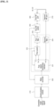
- the system for testing performance of a UWB antenna and a BLE antenna (hereinafter an antenna performance test system) is constructed to include a first antenna 120, a second antenna 140, a control terminal 200, and a tester 300.
- the first antenna 120 is disposed within the same shield box 20 as a test target terminal 10, and is connected to the tester 300 through a first RF cable 40.
- the first antenna 120 transmits and receives a signal having a UWB frequency band and a signal having a BLE frequency band. That is, when the mode of the tester 300 is set as a first test mode, the first antenna 120 transmits a first test signal having the UWB frequency band to the test target terminal 10, and receives a first response signal for the first test signal from the test target terminal 10.
- the mode of the tester 300 is set as a second test mode
- the first antenna 120 transmits the second test signal having the BLE frequency band to the test target terminal 10, and receives a second response signal for the second test signal from the test target terminal 10.
- the second antenna 140 is disposed within the same shield box 20 as the test target terminal 10, and is connected to the tester 300 through a second RF cable 50.
- the second antenna 140 is disposed to be spaced apart from the first antenna 120 at a predetermined interval within the shield box 20.
- the second antenna 140 transmits and receives the first response signal, that is, a signal having a UWB frequency band, which is output by the test target terminal 10.
- the control terminal 200 is a terminal that controls the tester 300 for an antenna performance test.
- the control terminal 200 may include a terminal, such as a smartphone, a tablet, or a desktop, which may control the tester 300.
- the control terminal 200 is connected to the tester 300 so that data communication is possible, and is connected to the tester 300 through a communication cable, such as a serial cable or a USB cable, for example.
- the control terminal 200 may be connected to a network, such as the Internet or Intranet, in order to transmit performance test results to a terminal or a server that is disposed outside a test room.
- the control terminal 200 outputs a control signal for operating the tester 300 in a correction mode. That is, when a manager requests entry into the correction mode through the control terminal 200, in response to the request for the entry into the correction mode, the control terminal 200 generates a correction mode setting signal and outputs the correction mode setting signal to the tester 300.
- the correction mode is a mode in which a correction value is set through the measurement of a loss of a cable, for example.
- the control terminal 200 outputs a control signal for operating the tester 300 in a test mode. That is, when a manager requests entry into the test mode through the control terminal 200, in response to the request for the entry into the test mode from the manager, the control terminal 200 generates a test mode setting signal and outputs the test mode setting signal to the tester 300. In this case, the control terminal 200 transmits one of a self-test mode setting signal, a first test mode setting signal, and a second test mode setting signal to the tester 300.
- the self-test mode setting signal is a control signal for testing an operation of the tester 300 by using a signal that is output to and received from the tester 300 itself.
- the first test mode setting signal is a control signal for setting the mode of the tester 300 as a UWB test mode.
- the second test mode setting signal is a control signal for setting the mode of the tester 300 as a BLE test mode.
- the control terminal 200 receives a performance measurement value from the tester 300, and stores and manages the performance measurement value. That is, the control terminal 200 stores at least one of a first communication performance measurement value and a second communication performance measurement value in association with unique information (e.g., a product number or a product name) of the test target terminal 10.
- unique information e.g., a product number or a product name
- the control terminal 200 receives the first communication performance measurement value, that is, a UWB communication performance measurement value, from the tester 300.
- the first communication performance measurement value is received signal strength indication (RSSI) of a UWB signal that is measured by the tester 300, for example.
- RSSI received signal strength indication
- the first communication performance measurement value may be a value in which a loss value of an RF cable (i.e., the first RF cable 40 and/or the second RF cable 50) has been incorporated into the RSSI of the UWB signal.
- the control terminal 200 receives a second communication performance measurement value, that is, a BLE communication performance measurement value, from the tester 300.
- the second communication performance measurement value is a perform packet error rate (PER) of a BLE signal, for example.
- the second communication performance measurement value may further include RSSI and a transmission power level of a BLE signal that is measured by the tester 300.
- the second communication performance measurement value may be a value in which a loss value of an RF cable (i.e., the first RF cable 40 and/or the second RF cable 50) has been incorporated into the RSSI of the BLE signal.
- the tester 300 operates in any one of the correction mode, the first test mode, and the second test mode. That is, the tester 300 operates in any one of the correction mode in which the tester 300 measures a loss of an RF cable in response to a request from the control terminal 200 and sets the measured loss as a correction value, the first test mode in which the tester 300 tests UWB communication performance, and the second test mode in which the tester 300 tests BLE communication performance.
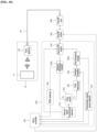
- the tester 300 is constructed to include a communication module 310, a micro controller 320, a first signal processing module 330, a second signal processing module 340, a first RF switch 350, a first RF port 360, and a second RF port 370.
- the communication module 310 is connected to the control terminal 200 so that data communication is possible.
- the communication module 310 may be connected to the control terminal 200 through a communication cable, such as a serial cable or a USB cable, or may be connected to the control terminal 200 over a network, such as the Internet or Intranet.
- the micro controller 320 controls an operation of the tester 300. That is, the micro controller 320 controls the tester 300 to operate in one of the correction mode in which the tester 300 measures a loss of an RF cable in response to a request from the control terminal 200 and sets the measured loss as a correction value, the first test mode in which the tester 300 tests UWB communication performance, and the second test mode in which the tester 300 tests BLE communication performance.
- the first signal processing module 330 operates only in the correction mode and the first test mode under the control of the micro controller 320.
- the first signal processing module 330 is a module that measures UWB communication performance, for example.
- the second signal processing module 340 operates only in the second test mode under the control of the micro controller 320.
- the second signal processing module 340 is a module that measures BLE communication performance, for example.
- the first RF switch 350 switches to one of the first signal processing module 330 and the second signal processing module 340 in response to a switching signal of the micro controller 320 so that the one signal processing module is connected to the first RF port 360.
- the first RF switch 350 switches to the first signal processing module 330 in response to a first switching signal of the micro controller 320, and forms a path between the first signal processing module 330 and the first RF port 360.
- the first RF switch 350 switches to the second signal processing module 340 in response to a second switching signal of the micro controller 320, and forms a path between the second signal processing module 340 and the first RF port 360.
- a first end of the first RF port 360 is connected to the first RF switch 350.
- a second end of the first RF port 360 is connected to the first RF cable 40 or the second RF cable 50. Accordingly, the first RF port 360 is connected to the second RF port 370.
- the first RF port 360 outputs a correction signal that is output by the first signal processing module 330 to the second RF port 370 through the first RF cable 40 or the second RF cable 50.
- the first RF port 360 may be connected to the first antenna 120 through the first RF cable 40.
- the first RF port 360 outputs a test signal that is output by the first signal processing module 330 or the second signal processing module 340 to the first antenna 120 through the first RF cable 40.
- the first RF port 360 receives a response signal that is received by the first antenna 120 from the test target terminal 10.
- the first RF port 360 outputs the received response signal to the first signal processing module 330 or the second signal processing module 340 through the first RF switch 350.
- a first end of the second RF port 370 may be connected to the first signal processing module 330.
- a second end of the second RF port 370 is connected to the first RF cable 40 or the second RF cable 50. Accordingly, the second RF port 370 is connected to the first RF port 360.
- the second RF port 370 receives a correction signal that is output by the first RF port 360, and outputs the correction signal to the first signal processing module 330.
- the second end of the second RF port 370 may be connected to the second antenna 140 through the second RF cable 50.
- the second RF port 370 receives a response signal that is received by the second antenna 140 from the test target terminal 10.
- the second RF port 370 outputs the received response signal to the first signal processing module 330 through the first RF switch 350.
- the tester 300 operates in the correction mode in response to a correction mode setting signal of the control terminal 200.
- the tester 300 operates in the correction mode and sets a correction value, that is, loss values of the first RF cable 40 and the second RF cable 50.
- the tester 300 operates in the correction mode upon initial installation of the antenna performance test system, upon replacement of an RF cable, or at intervals of a set period.
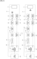
- the signal processing module is constructed to include a first signal processing element 331, a first switch 332, a first filter 333, and a second filter 334 in order to operate in the correction mode.
- the tester 300 operates in the correction mode in the state in which the first RF port 360 and the second RF port 370 have been connected by the first RF cable 40.
- the tester 300 may operate in a primary correction mode in the state in which the first RF cable 40 has been connected thereto, and may operate in a secondary correction mode in the state in which the second RF cable 50 has been connected thereto.
- the communication module 310 transmits a correction mode setting signal to the micro controller 320 in response to a correction mode setting signal of the control terminal 200.
- the micro controller 320 transmits a first switching signal to the first RF switch 350 in response to the correction mode setting signal of the communication module 310.
- the first RF switch 350 switches to the first signal processing module 330 in response to the first switching signal of the micro controller 320.
- the micro controller 320 transmits a correction start signal to the first signal processing element 331.
- the correction start signal is UWB data, for example.
- the first signal processing element 331 transmits a first switching signal to the first switch 332 in response to the correction start signal of the micro controller 320.
- the first switch 332 forms an output path between an output stage Tx of the first signal processing element 331 and the first filter 333 in response to the first switching signal of the first signal processing element 331.
- the first signal processing element 331 When the output path is formed, the first signal processing element 331 outputs a correction signal, that is, a UWB signal, to the first switch 332. In this case, the first signal processing element 331 outputs the correction signal having reference signal strength.
- the first switch 332 outputs the correction signal of the first signal processing element 331 to the first filter 333.
- the first filter 333 removes noise from the correction signal by filtering a signal having a UWB band, and then outputs the correction signal to the first RF port 360 through the first RF switch 350.
- the first RF port 360 outputs the correction signal to the RF cable.
- the RF cable outputs the correction signal to the second RF port 370.
- the second RF port 370 outputs the correction signal received from the RF cable to the second filter 334.
- the second filter 334 removes noise from the correction signal by filtering a signal having a UWB band and then output the correction signal.
- the correction signal output by the second filter 334 is input to a second input stage Rx2 of the first signal processing element 331.
- the first signal processing element 331 calculates a loss value of the first RF cable 40 by comparing reference signal strength of the correction signal that has been output to the output stage Tx and RSSI of the correction signal that has been input to the second input stage Rx2. That is, the first signal processing element 331 calculates the loss value of the first RF cable 40 by subtracting the RSSI from the reference signal strength.
- the tester 300 connects the second RF cable 50 to the first RF port 360 and the second RF port 370, and calculates a loss value of the second RF cable 50 by repeating the aforementioned process.
- the first signal processing element 331 sets the calculated loss value of the first RF cable 40 as a first correction value, and sets the calculated loss value of the second RF cable 50 as a second correction value.
- the first signal processing element 331 may be in the state in which the reference signal strength has been stored in its internal memory in order to set the correction value.
- the first signal processing element 331 may store the set first correction value and second correction value in the internal memory.
- the first signal processing element 331 may transmit the set first correction value and second correction value to the micro controller 320, and the micro controller 320 may store the first correction value and the second correction value.
- the antenna performance test system can test UWB communication performance and BLE communication performance of the test target terminal 10 by using one tester 300.
- control terminal 200 transmits a first test mode setting signal to the tester 300 in order to measure UWB communication performance of the test target terminal 10.
- the communication module 310 receives the first test mode setting signal of the control terminal 200 and outputs the first test mode setting signal to the micro controller 320.
- the micro controller 320 outputs a first switching signal to the first RF switch 350 in response to the first test mode setting signal.
- the first RF switch 350 forms a first test mode environment in which the first signal processing module 330 and the first antenna 120 and the second antenna 140 are connected by switching to the first signal processing module 330 in response to the first switching signal of the micro controller 320.
- the first signal processing module 330 When the first test mode environment is formed, the first signal processing module 330 outputs a first test signal, that is, a signal having a UWB band, through the first antenna 120, and measures UWB communication performance of the test target terminal 10 by using a first response signal that is received from each of the first antenna 120 and the second antenna 140.
- a first test signal that is, a signal having a UWB band
- the micro controller 320 After transmitting a first switching signal, the micro controller 320 outputs a first test signal, that is, a signal having a UWB band, to the first signal processing element 331.
- the first signal processing element 331 outputs a first switching signal to the first switch 332 in response to the first test signal of the micro controller 320.
- the first switch 332 forms a transmission path that connects the output stage Tx of the first signal processing element 331 and the first filter 333, in response to the first switching signal of the first signal processing element 331.
- the first signal processing element 331 When the transmission path is formed, the first signal processing element 331 outputs a first test signal to the first filter 333 through the first switch 332.
- the first filter 333 removes noise from the first test signal by filtering a signal having a UWB band, and then outputs the first test signal to the first RF port 360 through the first RF switch 350.
- the first RF port 360 outputs, to the first antenna 120, the first test signal that is input through the first filter 333 and the first RF switch 350.
- the first antenna 120 outputs the first test signal to the test target terminal 10 disposed within the shield box 20.
- the first signal processing element 331 outputs a second switching signal to the first switch 332.
- the first switch 332 forms a reception path that connects a first input stage Rx1 of the first signal processing element 331 and the first filter 333 in response to the second switching signal.
- the test target terminal 10 outputs a first response signal in response to the first test signal of the first antenna 120.
- the first antenna 120 and the second antenna 140 receive the first response signal output by the test target terminal 10.
- the first antenna 120 outputs the first response signal to the first RF port 360.
- the first RF port 360 outputs a first response signal to the first filter 333 through the first RF switch 350 in response to the first response signal of the first antenna 120.
- the first filter 333 removes noise from the first response signal by filtering a signal having a UWB band in response to the first response signal of the first RF port 360, and then outputs the first response signal to the first switch 332.
- the first switch 332 outputs the first response signal to the first input stage Rx1 of the first signal processing element 331 in response to the first response signal of the first filter 333.
- the second antenna 140 outputs the first response signal to the second RF port 370.
- the second RF port 370 outputs a first response signal to the second filter 334 in response to the first response signal of the second antenna 140.
- the second filter 334 removes noise from the first response signal by filtering a signal having a UWB band in response to the first response signal of the second RF port 370, and then outputs the first response signal to the second input stage Rx2 of the first signal processing element 331.
- the first signal processing element 331 measures UWB communication performance by using the first response signals input to the first input stage Rx1 and the second input stage Rx2.
- the first signal processing element 331 generates a UWB communication performance measurement value by measuring UWB communication performance by using the two first response signals and an angle of arrival (AoA) method.
- AoA angle of arrival
- the first signal processing element 331 generates a first communication performance measurement value by incorporating a first correction value and a second correction value into the UWB communication performance measurement value.
- the first signal processing element 331 outputs the first communication performance measurement value to the micro controller 320.
- the micro controller 320 generates a request for the transmission of the communication performance measurement value from the communication module 310, including the first communication performance measurement value, in response to the first communication performance measurement value of the first signal processing element 331.
- the micro controller 320 outputs the request for the transmission of the communication performance measurement value to the communication module 310.
- the communication module 310 transmits the first communication performance measurement value to the control terminal 200 in response to the request for the transmission of the communication performance measurement value, which has been received from the micro controller 320.
- the first signal processing element 331 may have a limited signal range in which the signal may be processed.
- the signal range is a voltage range or current range of a signal which may be processed by all signal processing modules, for example.
- the first signal processing module 330 may further include a first attenuator 335 that is disposed between the first switch 332 and the first input stage Rx1 of the first signal processing element 331 and a second attenuator 336 that is disposed between the second filter 334 and the second input stage Rx2 of the first signal processing element 331.
- the first attenuator 335 outputs, to the first input stage Rx1, the first response signal that is received through the first switch 332 by converting the first response signal into a signal included in the signal range of the first signal processing element 331.
- the second attenuator 336 outputs, to the second input stage Rx2, the first response signal that is received through the second filter 334 by converting the first response signal into a signal included in the signal range of the first signal processing element 331.
- an antenna performance test system may use three or more antennas in order to more accurately measure UWB communication performance of the test target terminal 10.
- the antenna performance test system includes the first antenna 120, the second antenna 140, and a third antenna 160.
- the tester 300 outputs a first test signal through the first antenna 120.
- the tester 300 receives a first response signal that is output by the test target terminal 10 through the first antenna 120, the second antenna 140, and the third antenna 160.
- the tester 300 measures UWB communication performance of the test target terminal 10 by using the first response signals that are received from the first antenna 120, the second antenna 140, and the third antenna 160 and an AoA determination method.
- the first signal processing element 331 outputs a first switching signal to the first switch 332 in response to the first test signal of the micro controller 320.
- the first switch 332 forms a transmission path that connects the output stage Tx of the first signal processing element 331 and the first filter 333, in response to the first switching signal of the first signal processing element 331.
- the first signal processing element 331 When the transmission path is formed, the first signal processing element 331 outputs the first test signal to the first filter 333 through the first switch 332.
- the first filter 333 removes noise from the first test signal by filtering a signal having a UWB band, and then outputs the first test signal to the first RF port 360 through the first RF switch 350.
- the first RF port 360 outputs, to the first antenna 120, the first test signal that is input through the first filter 333 and the first RF switch 350.
- the first antenna 120 outputs the first test signal to the test target terminal 10 disposed within the shield box 20.
- the first signal processing element 331 outputs a second switching signal to the first switch 332.
- the first switch 332 forms a reception path that connects the first input stage Rx1 of the first signal processing element 331 and the first filter 333, in response to the second switching signal.
- the test target terminal 10 outputs a first response signal in response to the first test signal of the first antenna 120.
- the first antenna 120, the second antenna 140, and the third antenna 160 receive the first response signal output by the test target terminal 10.
- the first antenna 120 outputs a first response signal to the first RF port 360.
- the first RF port 360 outputs the first response signal to the first filter 333 through the first RF switch 350 in response to the first response signal of the first antenna 120.
- the first filter 333 removes noise from the first response signal by filtering a signal having a UWB band in response to the first response signal of the first RF port 360, and then outputs the first response signal to the first switch 332.
- the first switch 332 outputs the first response signal to the first input stage Rx1 of the first signal processing element 331 in response to the first response signal of the first filter 333.
- the first signal processing element 331 When the output of the first test signal is completed or after the first test signal is output to the first switch 332, the first signal processing element 331 outputs a first switching signal to the second switch 338.
- the second switch 338 forms a reception path that connects the second input stage Rx2 and the second filter 334 in response to the first switching signal of the first signal processing element 331.
- the second antenna 140 outputs a first response signal to the second RF port 370.
- the second RF port 370 outputs the first response signal to the second filter 334 in response to the first response signal of the second antenna 140.
- the second filter 334 removes noise from the first response signal by filtering a signal having a UWB band in response to the first response signal of the second RF port 370, and then outputs the first response signal to the second input stage Rx2 of the first signal processing element 331 through the second switch 338.
- the first signal processing element 331 After the first response signal received from the second antenna 140 is received by the second input stage Rx2, the first signal processing element 331 outputs a second switching signal to the second switch 338.
- the second switch 338 forms a reception path that connects the second input stage Rx2 and the third filter 337 in response to the second switching signal of the first signal processing element 331.
- the third antenna 160 is connected to the third RF port 380 through the third RF cable 60, and outputs a first response signal to the third RF port 380.
- the third RF port 380 outputs the first response signal to the third filter 337 in response to the first response signal of the third antenna 160.
- the third filter 337 removes noise from the first response signal by filtering a signal having a UWB band in response to the first response signal of the third RF port 380, and then outputs the first response signal to the second input stage Rx2 of the first signal processing element 331 through the second switch 338.
- the first signal processing element 331 measures UWB communication performance by using the first response signals that have been input to the first input stage Rx1 and the second input stage Rx2.
- the first signal processing element 331 generates a UWB communication performance measurement value by measuring the UWB communication performance by using the three first response signals and the angle of arrival (AoA) method.
- the first signal processing element 331 generates a first communication performance measurement value by incorporating a first correction value and a second correction value into the UWB communication performance measurement value.
- the first signal processing element 331 outputs the first communication performance measurement value to the micro controller 320.
- the micro controller 320 generates a request for the transmission of the communication performance measurement value from the communication module 310, including the first communication performance measurement value, in response to the first communication performance measurement value of the first signal processing element 331.
- the micro controller 320 outputs the request for the transmission of the communication performance measurement value to the communication module 310.
- the communication module 310 transmits the first communication performance measurement value to the control terminal 200 in response to the request for the transmission of the communication performance measurement value, which has been received from the micro controller 320.
- the second attenuator 336 is disposed between the second input stage Rx2 of the first signal processing element 331 and the second switch 338.
- the second attenuator 336 outputs the first response signals that are input through the second filter 334 the third filter 337 to the second input stage Rx2 by converting the first response signals into a signal included in the signal range of the first signal processing element 331.
- control terminal 200 transmits a second test mode setting signal to the tester 300 in order to measure BLE communication performance of the test target terminal 10.
- the communication module 310 outputs the second test mode setting signal of the control terminal 200 to the micro controller 320 by receiving the second test mode setting signal.
- the micro controller 320 outputs a second switching signal to the first RF switch 350 in response to the second test mode setting signal.
- the first RF switch 350 forms a second test mode environment in which the second signal processing module 340 and the first antenna 120 are connected by switching to the second signal processing module 340 in response to the second switching signal of the micro controller 320.
- the second signal processing module 340 When the second test mode environment is formed, the second signal processing module 340 outputs a second test signal, that is, a signal having a BLE band, through the first antenna 120, and measures BLE communication performance of the test target terminal 10 by using a second response signal that is received from the first antenna 120.
- a second test signal that is, a signal having a BLE band
- the micro controller 320 After transmitting the second switching signal, the micro controller 320 outputs the second test signal, that is, a signal having a BLE band, to the second signal processing element 341.
- the second signal processing element 341 outputs a first switching signal to a third switch 342 and a second RF switch 343 in response to the second test signal of the micro controller 320.
- the third switch 342 switches to the third attenuator 344 in response to the first switching signal of the second signal processing element 341.
- the second RF switch 343 switches to a first directional coupler 346a in response to the first switching signal of the second signal processing element 341. Accordingly, a transmission path that connects the third attenuator 344, the variable amplifier 345, and the first directional coupler 346a is formed.
- the second signal processing element 341 When the transmission path is formed, the second signal processing element 341 outputs the second test signal to the third attenuator 344 through the third switch 342.
- the third attenuator 344 attenuates the power level (i.e., a voltage level or a current level) of the second test signal that is input through the third switch 342, and then outputs the second test signal to a variable amplifier 345.
- the variable amplifier 345 outputs the second test signal output by the third attenuator 344 to the first directional coupler 346a by amplifying the power level of the second test signal.
- the first directional coupler 346a outputs the second test signal to the transmission signal power detector 347.
- the transmission signal power detector 347 detects the power level of the second test signal, and outputs the second test signal to the micro controller 320.
- the micro controller 320 generates an amplification value for amplifying, by the variable amplifier 345, the second test signal into a signal having a set power level in response to the power level of the first directional coupler 346a.
- the micro controller 320 generates a power level control signal including the generated amplification value and outputs the power level control signal to the variable amplifier 345.
- the variable amplifier 345 amplifies the level of the second test signal output by the third attenuator 344 as a power level corresponding to the amplification value in response to the power level control signal of the micro controller 320.
- the second test signal amplified by the variable amplifier 345 is output to the first directional coupler 346a.
- the first directional coupler 346a outputs the second test signal to the first RF port 360 through the second RF switch 343 and the first RF switch 350.
- the first RF port 360 outputs the second test signal to the first antenna 120.
- the first antenna 120 outputs the second test signal to the test target terminal 10 disposed within the shield box 20.
- the second signal processing element 341 outputs a second switching signal to the third switch 342 and the second RF switch 343.
- the third switch 342 and the second RF switch 343 switch to the second directional coupler 346b in response to the second switching signal of the second signal processing element 341. Accordingly, a reception path that connects the third switch 342, the second directional coupler, and the second RF switch 343 is formed.
- the test target terminal 10 outputs a second response signal in response to the second test signal of the first antenna 120.
- the first antenna 120 receives the second response signal output by the test target terminal 10.
- the first antenna 120 outputs the second response signal to the first RF port 360.
- the first RF port 360 outputs the second response signal to the second directional coupler 346b through the first RF switch 350 and the second RF switch 343 in response to the second response signal of the first antenna 120.
- the second directional coupler 346b outputs the second response signal to an RSSI detector 348.
- the RSSI detector 348 detects RSSI of the second response signal and outputs the RSSI to the micro controller 320. Furthermore, the second directional coupler 346b outputs the second response signal to the second signal processing element 341 through the third switch 342.
- the antenna performance test system has an effect in that it can more accurately measure BLE communication performance because the antenna performance test system can measure the power level of a transmission signal and the sensitivity of a received signal along with the PER by connecting the directional couplers to the transmission path and the reception path, unlike in a conventional technology in which only PER performance of BLE communication is measured.
- the second signal processing module 340 may further include a low noise amplifier 349 that is disposed between the second directional coupler 346b and the RSSI detector 348.
- the low noise amplifier 349 amplifies the second response signal that is output to the second directional coupler 346b so that the RSSI detector 348 can more accurately measure RSSI of the second response signal.
Landscapes
- Physics & Mathematics (AREA)
- Electromagnetism (AREA)
- General Physics & Mathematics (AREA)
- Engineering & Computer Science (AREA)
- Computer Networks & Wireless Communication (AREA)
- Signal Processing (AREA)
- Monitoring And Testing Of Transmission In General (AREA)
- Mobile Radio Communication Systems (AREA)
- Mathematical Physics (AREA)
Applications Claiming Priority (2)
| Application Number | Priority Date | Filing Date | Title |
|---|---|---|---|
| KR1020210098249A KR102682724B1 (ko) | 2021-07-27 | 2021-07-27 | Uwb 안테나 및 ble 안테나 성능 시험 시스템 |
| PCT/KR2022/010270 WO2023008790A1 (fr) | 2021-07-27 | 2022-07-14 | Système de test de performances d'une antenne uwb et d'une antenne ble |
Publications (2)
| Publication Number | Publication Date |
|---|---|
| EP4380077A1 true EP4380077A1 (fr) | 2024-06-05 |
| EP4380077A4 EP4380077A4 (fr) | 2024-11-27 |
Family
ID=85087415
Family Applications (1)
| Application Number | Title | Priority Date | Filing Date |
|---|---|---|---|
| EP22849766.5A Pending EP4380077A4 (fr) | 2021-07-27 | 2022-07-14 | Système de test de performances d'une antenne uwb et d'une antenne ble |
Country Status (4)
| Country | Link |
|---|---|
| US (1) | US12487263B2 (fr) |
| EP (1) | EP4380077A4 (fr) |
| KR (1) | KR102682724B1 (fr) |
| WO (1) | WO2023008790A1 (fr) |
Families Citing this family (1)
| Publication number | Priority date | Publication date | Assignee | Title |
|---|---|---|---|---|
| US12375190B2 (en) * | 2023-08-14 | 2025-07-29 | Hewlett Packard Enterprise Development Lp | Power compensation determination for radio frequency cable |
Family Cites Families (10)
| Publication number | Priority date | Publication date | Assignee | Title |
|---|---|---|---|---|
| US8527229B2 (en) * | 2010-08-31 | 2013-09-03 | Apple Inc. | Test systems with multiple antennas for characterizing over-the-air path loss |
| US9319908B2 (en) | 2011-10-12 | 2016-04-19 | Apple Inc. | Methods for reducing path loss while testing wireless electronic devices with multiple antennas |
| US9164159B2 (en) * | 2012-12-14 | 2015-10-20 | Apple Inc. | Methods for validating radio-frequency test stations |
| US9678126B2 (en) | 2013-03-15 | 2017-06-13 | Litepoint Corporation | System and method for testing radio frequency wireless signal transceivers using wireless test signals |
| US9404965B2 (en) * | 2013-12-20 | 2016-08-02 | Apple Inc. | Radio-frequency test system with tunable test antenna circuitry |
| KR101937227B1 (ko) | 2016-07-15 | 2019-01-11 | 주식회사 테스콤 | 안테나 구동 기반의 테스트 시스템 |
| US10284456B2 (en) * | 2016-11-10 | 2019-05-07 | Contec, Llc | Systems and methods for testing electronic devices using master-slave test architectures |
| CN206686190U (zh) * | 2017-05-08 | 2017-11-28 | 安徽江淮汽车集团股份有限公司 | 蓝牙通讯测试装置 |
| US11349518B2 (en) * | 2017-11-16 | 2022-05-31 | Amosense Co., Ltd. | Cover for portable terminal |
| KR20200144010A (ko) | 2019-06-17 | 2020-12-28 | 주식회사 이노와이어리스 | 다중 안테나를 갖는 단말을 위한 무선 연결 장치 |
-
2021
- 2021-07-27 KR KR1020210098249A patent/KR102682724B1/ko active Active
-
2022
- 2022-07-14 WO PCT/KR2022/010270 patent/WO2023008790A1/fr not_active Ceased
- 2022-07-14 US US18/293,029 patent/US12487263B2/en active Active
- 2022-07-14 EP EP22849766.5A patent/EP4380077A4/fr active Pending
Also Published As
| Publication number | Publication date |
|---|---|
| US20240248126A1 (en) | 2024-07-25 |
| KR20230016802A (ko) | 2023-02-03 |
| US12487263B2 (en) | 2025-12-02 |
| WO2023008790A1 (fr) | 2023-02-02 |
| EP4380077A4 (fr) | 2024-11-27 |
| KR102682724B1 (ko) | 2024-07-08 |
Similar Documents
| Publication | Publication Date | Title |
|---|---|---|
| US10819446B2 (en) | Radar transmitting power and channel performance monitoring apparatus | |
| EP3544323A1 (fr) | Procédé permettant de déterminer un retard temporel de canal, procédé de localisation et dispositif associé | |
| US9979496B2 (en) | System and method for calibration and monitoring of an anechoic boundary array RF environment simulator | |
| CN107959515B (zh) | 多天线噪声功率的测量方法和装置 | |
| KR100316691B1 (ko) | 스위치를 이용한 기지국 안테나 점검장치 및 방법 | |
| US8174446B2 (en) | Signal path delay determination | |
| CN107872284B (zh) | 无线直放站的自激检测方法及装置 | |
| US11044027B2 (en) | Wireless transmission performance test system and method thereof | |
| CN102025433A (zh) | 信号检测方法、装置和基站 | |
| US12196796B2 (en) | System for testing antenna performance | |
| CN111337952B (zh) | 用于满天星抗干扰测试系统的信号在线监测方法和装置 | |
| EP4380077A1 (fr) | Système de test de performances d'une antenne uwb et d'une antenne ble | |
| US20150139023A1 (en) | System and method for data packet transceiver testing after signal calibration and power settling to minimize test time | |
| KR20120072111A (ko) | 벡터 네트워크 분석기를 이용한 칼리브레이션 방법 및 이를 이용한 지연시간 측정 방법 | |
| CN104917574A (zh) | 短距离电力通信用无线通信测试系统自校准方法 | |
| CN107592165B (zh) | 一种测试路由器发送功率的方法及系统 | |
| WO2020217088A1 (fr) | Procédé et appareil d'étalonnage par radio pour une surveillance de vswr d'antenne intégrée | |
| CN114866163A (zh) | 射频校准电路、电子设备及射频校准方法 | |
| CN118465796B (zh) | 射频电缆硬件延迟测试方法、装置、电子设备及存储介质 | |
| CN111382587B (zh) | 射频读写器、测试信号的选择方法及存储介质 | |
| CN115913282B (zh) | 一种漏泄电缆性能评估方法、装置、电子设备及存储介质 | |
| CN114501291A (zh) | 耳机抗干扰测试方法及装置 | |
| CN111224723B (zh) | 射频前端模块的校准方法、系统、电子设备及存储介质 | |
| CN112666406A (zh) | 收发同频率通信制式天线的接收灵敏度的快速测试方法 | |
| US20250286571A1 (en) | Receiver, system comprising such a receiver, and receiving method |
Legal Events
| Date | Code | Title | Description |
|---|---|---|---|
| STAA | Information on the status of an ep patent application or granted ep patent |
Free format text: STATUS: THE INTERNATIONAL PUBLICATION HAS BEEN MADE |
|
| PUAI | Public reference made under article 153(3) epc to a published international application that has entered the european phase |
Free format text: ORIGINAL CODE: 0009012 |
|
| STAA | Information on the status of an ep patent application or granted ep patent |
Free format text: STATUS: REQUEST FOR EXAMINATION WAS MADE |
|
| 17P | Request for examination filed |
Effective date: 20240122 |
|
| AK | Designated contracting states |
Kind code of ref document: A1 Designated state(s): AL AT BE BG CH CY CZ DE DK EE ES FI FR GB GR HR HU IE IS IT LI LT LU LV MC MK MT NL NO PL PT RO RS SE SI SK SM TR |
|
| DAV | Request for validation of the european patent (deleted) | ||
| DAX | Request for extension of the european patent (deleted) | ||
| A4 | Supplementary search report drawn up and despatched |
Effective date: 20241028 |
|
| RIC1 | Information provided on ipc code assigned before grant |
Ipc: G01R 29/08 20060101ALI20241022BHEP Ipc: G01R 29/10 20060101ALI20241022BHEP Ipc: G01R 23/165 20060101ALI20241022BHEP Ipc: H04B 17/29 20150101ALI20241022BHEP Ipc: H04B 17/19 20150101AFI20241022BHEP |