EP4380313A2 - Appareil de cuisson domestique ayant un capteur mobile longitudinalement par la puissance d'un moteur - Google Patents
Appareil de cuisson domestique ayant un capteur mobile longitudinalement par la puissance d'un moteur Download PDFInfo
- Publication number
- EP4380313A2 EP4380313A2 EP24164841.9A EP24164841A EP4380313A2 EP 4380313 A2 EP4380313 A2 EP 4380313A2 EP 24164841 A EP24164841 A EP 24164841A EP 4380313 A2 EP4380313 A2 EP 4380313A2
- Authority
- EP
- European Patent Office
- Prior art keywords
- sensor
- cooking chamber
- guide sleeve
- sleeve
- closure element
- Prior art date
- Legal status (The legal status is an assumption and is not a legal conclusion. Google has not performed a legal analysis and makes no representation as to the accuracy of the status listed.)
- Pending
Links
Images
Classifications
-
- H—ELECTRICITY
- H05—ELECTRIC TECHNIQUES NOT OTHERWISE PROVIDED FOR
- H05B—ELECTRIC HEATING; ELECTRIC LIGHT SOURCES NOT OTHERWISE PROVIDED FOR; CIRCUIT ARRANGEMENTS FOR ELECTRIC LIGHT SOURCES, IN GENERAL
- H05B6/00—Heating by electric, magnetic or electromagnetic fields
- H05B6/64—Heating using microwaves
- H05B6/6447—Method of operation or details of the microwave heating apparatus related to the use of detectors or sensors
- H05B6/645—Method of operation or details of the microwave heating apparatus related to the use of detectors or sensors using temperature sensors
- H05B6/6455—Method of operation or details of the microwave heating apparatus related to the use of detectors or sensors using temperature sensors the sensors being infrared detectors
-
- F—MECHANICAL ENGINEERING; LIGHTING; HEATING; WEAPONS; BLASTING
- F24—HEATING; RANGES; VENTILATING
- F24C—DOMESTIC STOVES OR RANGES ; DETAILS OF DOMESTIC STOVES OR RANGES, OF GENERAL APPLICATION
- F24C7/00—Stoves or ranges heated by electric energy
- F24C7/08—Arrangement or mounting of control or safety devices
- F24C7/082—Arrangement or mounting of control or safety devices on ranges, e.g. control panels, illumination
- F24C7/085—Arrangement or mounting of control or safety devices on ranges, e.g. control panels, illumination on baking ovens
Definitions
- the invention relates to a household cooking appliance, having a cooking chamber delimited by a cooking chamber wall, wherein a motor-driven longitudinally displaceable sensor is present, which can be moved from a rest position further away from the cooking chamber to a measuring position closer to the cooking chamber, and vice versa.
- the invention also relates to a corresponding method.
- the invention is particularly advantageously applicable to cooking appliances with a microwave function, e.g. stand-alone microwave devices or ovens with a microwave function.
- WO 2015/141207 A1 discloses a heating cooker equipped with: an infrared sensor provided on the outside of a heating chamber and using a plurality of infrared detection elements to detect the temperature of an object to be heated; and a direction adjustment motor that can change the direction of the infrared sensor.
- the heating cooker is configured so that the direction of the infrared sensor moves to a temperature detection position when temperature detection is performed, and the direction of the infrared sensor moves to a standby position when temperature detection is not performed.
- US 7 696 454 B2 discloses a cooking device having a device housing with a burner that heats an object.
- a first image capture device may be provided on a side of the device housing, wherein the first image capture device may be configured to capture image information corresponding to a heat source generated by the burner.
- a display may be provided on a side of the device housing to display the image information captured by the first image capture device.
- EP 0 924 964 A2 reveals a microwave oven. This has an infrared sensor for detecting the temperature of food during cooking. The sensor is directed diagonally downwards and backwards from the upper front edge of the cooking chamber. A cap protects the sensor when it is not needed to measure food temperature.
- EN 10 2017 220 889 A1 discloses an oven, in particular a pyrolysis oven, having an oven tube which delimits a cooking chamber, an opening leading through the oven tube, a sensor device with at least one sensor element which is arranged on the side of the oven tube facing away from the cooking chamber and is directed through the opening into the oven tube, and a protective device with at least one additional sensor, wherein the protective device is designed to detect a critical thermal state of the sensor device by means of the at least one additional sensor and upon detection of the critical thermal state at least one protective measure can be triggered which is suitable for reducing a thermal load on the at least one sensor element of the sensor device.
- EN 10 2017 220 886 A1 discloses an oven having an oven tube that encloses a cooking chamber, an outer housing, a sensor device directed into the cooking chamber, which is arranged in an interior space between the oven tube and the outer housing, and at least one sensor fan for ventilating the sensor device with cooling air
- the sensor device has a tubular sensor housing that is open at the front, in which at least one sensor element is accommodated and whose front end is directed in the direction of the cooking chamber, the sensor device has at least one viewing window arranged between the sensor element and the cooking chamber, a rear end of the sensor housing serves as an air inlet opening for cooling air, a pressure side of the sensor fan is connected to the rear end, the sensor housing has a lateral air outlet opening for the cooling air and a suction side of the sensor fan is connected to a space that is separated from the space of the sensor device.
- the oven is in particular a pyrolysis-capable oven.
- WO 2019/208527 A1 discloses a heating cooking apparatus equipped with: a heating chamber in which an object to be heated is accommodated; a wall surface opening which is an opening provided in a wall of the heating chamber; a support frame provided on the outside of the heating chamber to cover the wall surface opening; and a camera provided on the support frame so that an imaging surface can be projected through the wall surface opening to the interior of the heating chamber.
- the heating cooking device is equipped with: a shutter that can open/close to block or open the imaging surface of the camera and that is provided between the wall surface opening and the camera; and a fan that blows an airflow toward the camera and the shutter.
- the support frame has an air duct for sucking the airflow blown out by the fan and discharging it toward the heating chamber through the wall surface opening that has been guided to the surface.
- This cooking appliance offers the advantage of a particularly robust and at the same time simple and cost-effective way of exposing a sensor to a cooking chamber or a cooking chamber atmosphere and at least protecting it thermally from the cooking chamber.
- the sensor and the closure element can be moved between the rest position and the measuring position or the closed position and the open position with just one common drive.
- Using the guide sleeve has the additional advantage that it requires very little space outside the installation space.
- the senor can be temporarily placed in its measuring position without having to remain in this position permanently and being exposed to aggressive cooking chamber conditions such as high temperatures, an aggressive atmosphere, etc.
- sensors can also be used that can measure briefly in the measuring position (active position) without damage, but would not be able to withstand the cooking chamber conditions prevailing there permanently.
- the household cooking appliance can be, for example, an oven, microwave, steam treatment device or any combination thereof, e.g. an oven with microwave and/or steam treatment function.
- the cooking chamber wall can also be referred to as a muffle or oven pipe, especially in an oven.
- a sleeve can be understood in particular as a tubular or hollow-cylindrical receptacle or housing for the sensor.
- the sleeve is in particular straight (linear longitudinal axis), but can also be curved (curved longitudinal axis).
- the sleeve can, for example, have a circular, oval, square or free-form cross-section.
- the guide sleeve has a diameter between 10 mm and 20 mm, in particular between 11 mm and 20 mm, in particular between 15 mm and 17 mm, very particularly of approx. 16 mm.
- a sensor e.g. an IR sensor, can, for example, have a typical diameter of approx. 10 mm.
- the guide sleeve is present on the cooking chamber wall can, in a further development, include the guide sleeve being a separately manufactured Component that is inserted into a suitable opening in the cooking chamber wall.
- the guide sleeve can be flush with the cooking chamber wall, whereby the front opening of the guide sleeve on the cooking chamber side can then be flush with the cooking chamber wall.
- the guide sleeve can protrude through the cooking chamber wall into the cooking chamber.
- the guide sleeve is present on the cooking chamber wall can, in a further development, mean that it is designed as an outward-facing protuberance of the cooking chamber wall, i.e. represents an area of the cooking chamber wall.
- One advantage of this development is that it eliminates the need for a separate manufacture and attachment of the guide sleeve to the cooking chamber wall. This also implicitly provides an electrical connection between the guide sleeve and the cooking chamber wall, which is particularly advantageous for cooking appliances with a microwave function, as it makes it particularly easy to shield microwave radiation in the area of the guide sleeve.
- the fact that the sensor is accommodated in the guide sleeve so that it can be moved longitudinally by a motor means that the sensor can be moved along a longitudinal extension of the guide sleeve or in the longitudinal direction of the guide sleeve by means of a motor.
- the sensor can be arranged in its measuring position inside the guide sleeve (typically close to the front opening of the guide sleeve on the cooking chamber side), flush with the front opening on the cooking chamber side or even protrude into the cooking chamber through the front opening on the cooking chamber side.
- closure element can be moved together with the sensor by a motor means in particular that the movement of the closure element takes place together with the movement of the sensor. It is a further development that the closure element and the sensor can be moved by the same motor.
- the motor can be an electric motor, for example.
- the closure element is in particular between a closed position in which it closes the front opening on the cooking chamber side, in particular sits on it, and an open position in which it is separated from the front opening on the cooking chamber side of the guide sleeve is lifted off, movable.
- the movements of the sensor and the closure element are coordinated with one another in such a way that when the sensor is in its rest position, the closure element is in its closed position, and when the sensor is in its measuring position, the closure element is in its open position.
- the closure element can, for example, be disk-shaped.
- closure element releases the front opening on the cooking chamber side for the sensor
- the sensor is enabled or enabled to take measurements of the cooking chamber and/or the cooking chamber contents when the front opening is released.
- the sensor can therefore also be referred to as a "cooking chamber sensor”.
- the closure element When the closure element is closed, in which it closes the front opening on the cooking chamber side, the closure element blocks the sensor and the sensor cannot take any practically useful measurement of the cooking chamber or the cooking chamber contents.
- the at least one sensor comprises at least one infrared (IR) sensor, in particular at least one IR sensor (MIR sensor) measuring in the mid-infrared range (at typical wavelengths between 3 ⁇ m and 50 ⁇ m, for example).
- IR infrared
- MIR sensor IR sensor measuring in the mid-infrared range (at typical wavelengths between 3 ⁇ m and 50 ⁇ m, for example).
- the at least one IR sensor can then, for example, take thermal images of the cooking chamber and its contents, in a further development in different spectral ranges if there are several IR sensors.
- the at least one IR sensor can be an IR camera sensor, which generates thermal images in particular in pixel-like structures.
- the use of such an openable closure element is particularly advantageous for IR sensors, because alternatively usable IR-permeable protective lenses are very expensive and susceptible to contamination.
- the at least one sensor comprises at least one sensor sensitive in the visible spectral range (“camera sensor”).
- the opened closure element analogous to the IR sensor, releases a field of view of the at least one camera sensor for recording images from the cooking chamber.
- the at least one sensor comprises at least one ultrasonic sensor.
- the at least one sensor comprises at least one sensor that is set up to determine a property of the atmosphere to be measured (“atmosphere sensor”), e.g. an oxygen sensor, a humidity sensor, a sensor for detecting certain chemical substances, etc.
- atmosphere sensors must, by design, come into contact with the medium to be measured (the cooking chamber atmosphere), but do not use a field of view. Rather, in this case it is sufficient that the opened closure element is raised far enough from the front opening on the cooking chamber side that the sensor is exposed to the cooking chamber atmosphere to a practically sufficient extent.
- a further sleeve (“sensor sleeve”) is housed in the guide sleeve so that it can be moved longitudinally by a motor, the at least one sensor is attached to a front side of the sensor sleeve on the cooking chamber side, and the sensor sleeve is connected to the closure element via a mechanical connecting means, in particular a rod.
- This embodiment has the advantage that the sensor sleeve and thus the at least one sensor can be guided particularly easily and reliably through the guide sleeve.
- the guide sleeve and the sensor sleeve can be moved longitudinally relative to one another.
- a further advantage of the sensor sleeve is that a sensor can be attached to it easily and safely, in particular it can be inserted into the front side on the cooking chamber side. Another advantage is that electrical cables of the sensor can be easily laid through the sensor sleeve.
- the sleeve is designed as a rack into which a gear wheel driven by a motor engages.
- provided in the guide sleeve for this purpose, an outer side of the sensor sleeve can be formed, for example, with a row of teeth.
- the sleeve when designed as a rack, can protrude permanently (i.e. also in the measuring position) from a rear end face of the guide sleeve in order to easily ensure permanent engagement of the gear in the rack.
- the guide sleeve can have an opening through which the gear can engage with the toothing of the sensor sleeve. This means that the sensor sleeve can be made significantly shorter than if it had to protrude from the side of the guide sleeve facing away from the cooking chamber in the measuring position.
- the drive unit does not then have to be arranged at one end of the guide sleeve, but can also be arranged next to the guide sleeve to save space.
- the sensor sleeve can have an external thread, so that the inner sensor sleeve can be moved linearly by rotating a motor-driven threaded nut that engages the external thread.
- the drive (motor) can be arranged at the end of the guide sleeve facing away from the cooking chamber. This can be the case, for example, with a direct drive of the sensor sleeve via a hollow motor axle (with an internal spindle thread).
- the closure element is a pivotable closure flap.
- a pivot axis of the closure flap can be formed, for example, with the guide sleeve or with the cooking chamber.
- the movement of the sensor can be transmitted particularly easily if the closure flap is connected to the sensor sleeve via a pivotable rod. If the sensor sleeve is moved from the rest position to the measuring position, it presses the rod the closure flap. If the sensor sleeve is moved from the measuring position to the rest position, it pulls the closure flap back from its open position to the closed position.
- the closure element is firmly connected to the sensor, in particular the sensor sleeve, and can be moved or is moved in a similar way to the sensor or the sensor sleeve.
- This further development is particularly advantageous for non-imaging or imaging sensors such as humidity sensors, etc. and is particularly simple and robust to implement.
- the closure element can be spaced from the front side of the sensor sleeve on the cooking chamber side, for example via one or more rods or pins. If the sensor moves from the rest position to its measuring position, the closure element is moved analogously from the mouth opening on the cooking chamber side (in particular linearly) and thus lifted off until an opening position in front of the mouth opening on the cooking chamber side is reached.
- closure element when the sensor is moved back from the measuring position to its rest position, the closure element is placed back on the mouth opening on the cooking chamber side by a corresponding (in particular linear) movement.
- a closure element can also be referred to as a closure cover. It can in particular be disk-shaped.
- closure element is made at least partially from a material that is a poor conductor of heat. This has the advantage that when the sensor is in its rest position and the closure element closes the guide tube against the cooking chamber, thermal loading of the interior of the guide sleeve in which the sensor is located can be reduced.
- the closure element can, for example, be made at least partially from plastic.
- the household cooking appliance has a microwave function and the closure element is designed to be microwave-tight in its overlap area with the front opening of the guide sleeve on the cooking chamber side. This prevents leakage of microwave radiation from the cooking chamber through the front opening on the cooking chamber side into the guide sleeve. This in turn reduces the load on the sensor and can also prevent or
- the closure element can be made of metal, for example.
- the closure element is partially made of a material that is a poor conductor of heat and is microwave-tight in the area where it overlaps the front opening of the guide sleeve on the cooking chamber side.
- the closure element can be made of metal on one side, e.g. (in the closed position) the side facing the cooking chamber, and made of plastic on the other side, e.g. (in the closed position) the side facing the guide sleeve.
- the metal side can be formed, for example, by a metal coating on a base body made of plastic.
- the closure element can have a sandwich structure made of a metal layer and a non-metal layer with good heat insulation.
- the guide sleeve is designed to be electrically conductive on the casing side and is electrically connected to the cooking chamber wall. This advantageously also ensures that the guide sleeve itself is microwave-tight, because the metal tube (guide sleeve) formed thereby achieves a so-called cut-off effect of a thin tube cross-section and, as a result, no microwave leakage radiation is discharged through the guide sleeve. This applies in particular if the (inner) diameter of the guide sleeve is smaller than 25 mm.
- the guide sleeve in particular its outer surface, can have holes or recesses to advantageously enable an air flow through the guide sleeve, e.g. to cool the at least one sensor.
- a conventionally installed device cooling fan or a dedicated fan can be used, for example. If the household cooking appliance has a microwave function, it is particularly advantageous if the holes are so small that they do not affect microwave resistance.
- closure element in the rest position sits hermetically on the front opening of the guide sleeve on the cooking chamber side.
- This design can be implemented, for example, by the flap and/or the guide sleeve having a sealing ring or being provided with a sealing material in the contact area.
- the at least one sensor has at least one IR sensor and an inner surface of the closure element has an emissivity of almost 1 in the IR spectral range of the sensor, at least in its overlap area with the guide sleeve.
- This can also be expressed in such a way that the closure element is designed as an almost ideal black radiator on its side facing the interior of the guide sleeve (in the closed position), the emissivity of which is therefore approximately 1.
- An IR sensor looks at least partially at this overlap area in its rest position.
- This embodiment has the advantage that the IR sensor can be calibrated when the temperature of the cooking chamber is known, since it is assumed that the temperature in the overlap area corresponds to the temperature of the cooking chamber and the IR sensor can thus correlate or calibrate the wavelength of the IR light measured in the overlap area with the cooking chamber temperature.
- the cooking chamber temperature can be sensed, for example, using a dedicated cooking chamber temperature sensor, e.g. using a thermocouple or other measuring sensor.
- the object is also achieved by a method for operating a household cooking appliance as described above.
- the method can be designed analogously to the household appliance, and vice versa, and has the same advantages.
- a method for operating a household cooking appliance having a cooking chamber delimited by a cooking chamber wall, wherein a guide sleeve with a cooking chamber-side front opening opening into the cooking chamber is present on the cooking chamber wall, a sensor is accommodated in the guide sleeve so as to be longitudinally displaceable by motor and the cooking chamber-side front opening can be closed by means of a closure element which can be moved by motor together with the sensor, wherein Method by actuating a drive motor, the sensor is optionally moved from a rest position further away from the front opening on the cooking chamber side to a measuring position closer to the front opening on the cooking chamber side, and the closure element is moved from its closed position closing the front opening on the cooking chamber side to its open position releasing the front opening on the cooking chamber side for the sensor, or vice versa.
- the at least one sensor is moved into its measuring position during a treatment process or sequence of the household appliance, such as a cooking process, in order to take measurements from the cooking chamber (images, thermal images, ultrasound measurement, moisture measurement, etc.).
- the at least one sensor is moved to its measuring position in order to take measurements from the cooking chamber and is moved back to the rest position after a measurement or measuring phase ("intermittent measurement"). This can be advantageous for protecting the at least one sensor, especially when continuous measurement is not necessary.
- the at least one sensor is moved to its measuring position in order to take measurements from the cooking chamber and is only moved back to its rest position when at least one predetermined criterion is met, which indicates that the sensor could be dirty and/or damaged.
- the at least one sensor can be moved back to its rest position when the cooking chamber temperature reaches or exceeds a certain threshold value.
- the senor is an IR sensor
- an inner surface of the closure element has an emissivity of almost 1 at least in its overlap area with an interior of the guide sleeve in the spectral range of the sensor and a cooking chamber temperature of the cooking chamber is sensed by means of a temperature sensor, wherein in the method the sensor is calibrated by comparing the thermal radiation sensed on the inner surface of the closure element and the cooking chamber temperature sensed by means of the temperature sensor.
- the typically homogeneous temperature distribution in the cooking chamber of the switched-off cooking appliance can be used to calibrate the IR sensor, since in this state the cooking chamber temperature measured by the cooking appliance's temperature sensor corresponds very well with the temperature of adjacent components and thus the temperature of the closure element.
- calibration at higher temperatures is also possible, especially if, for example, it is known from an allocation table how the cooking chamber temperature and the temperature of the closure element relate to each other.
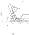
- Fig.1 shows a sectional side view of components of a household cooking appliance 1 in the form of a combined baking/microwave oven.
- a muffle 2 is specifically shown, which also serves as the cooking chamber wall 3 of a cooking chamber 4.
- a dome 5 is shown, in particular in the middle, for receiving a rotating antenna (not shown), via which microwaves can be fed into the cooking chamber 4.
- the dome 5 is separated from the actual cooking chamber 4 by a microwave-permeable cover 6.
- a guide sleeve 8 in the form of a straight, circular cylindrical tube is arranged on the ceiling 3a.
- This has a flange-like bent edge 10 on its front opening 9 on the cooking chamber side, which opens into the cooking chamber 4.
- the guide sleeve 8 is a separately manufactured component that comes out of the cooking chamber 4 through a A breakthrough or hole has been made in the ceiling 3a so that the edge 10 rests on the inside of the ceiling 3a and is attached there in an airtight manner, e.g. by laser welding.
- the edge 10 is designed to be inclined to a longitudinal axis of the guide sleeve 8 so that the mounted guide sleeve 8 is inclined. This improves the view into the cooking chamber 4 when the guide sleeve 8 is arranged off-center.
- the guide sleeve 8 is made of metal, it is electrically connected to the cooking chamber wall 8, which is also made of metal.
- the diameter of the guide sleeve 8 is approximately 16 mm and is therefore impermeable to microwaves with frequency ranges around 915 MHz or 2.45 GHz, which are typical for household microwave devices, in the case of a metal or metal-coated version.
- the guide sleeve 8 can have small holes or recesses which in particular do not affect microwave resistance. This allows better cooling of the at least one sensor 14, since the cooling air flow of a usually installed device cooling fan (not shown) can also be used to generate an air flow through the guide sleeve 8.
- a sensor sleeve 11 is accommodated in the guide sleeve 8 so that it can be moved longitudinally by a motor. This is achieved by the fact that an outside of the sensor sleeve 11 is designed with a row of teeth 12 extending in the longitudinal direction and the guide sleeve 8 has a recess 20 in its outer surface or side wall through which the row of teeth 12 is exposed.
- the household cooking appliance 1 also has an electric motor 21, on whose drive shaft a gear 22 is attached, the gear rim of which in turn engages the row of teeth 12 through the recess 20.
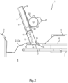
- the sensor sleeve 11 By actuating the electric motor 21 and corresponding rotation of the gear 22, the sensor sleeve 11 can be moved between two end positions, as indicated by the double arrow P1, namely between the measuring position shown and a position which is explained in more detail below and in Fig.2 shown resting position.
- a sensor here an IR sensor 14, is installed on the cooking chamber side face 13 of the sensor sleeve 11, which in the variant shown is flush with the cooking chamber side face 13.
- the IR sensor 14 is therefore also housed in the guide sleeve 8 so that it can be moved longitudinally by a motor. It can be moved out of the guide sleeve 8 outside of the rest position - as shown for the measuring position.
- the IR sensor can, for example, have a diameter of approx. 10 mm, which then corresponds to the inner diameter of the tubular sensor sleeve 11
- a rod 15 is rotatably connected to the sensor sleeve 11 and projects towards the cooking chamber side in relation to the sensor sleeve 11.
- the rod 15 is connected to a closure flap 17 which is pivotably attached to the edge 10 via a hinge 16, which enables the closure flap 17 to move, as indicated by the double arrow P2.
- the other end region of the rod 15 is rotatably connected to a projection 19 which stands up in an overlap region 18 of the closure flap 17.
- the closure flap 17 with the rod 15 is pivoted so far away from the front side 13 of the sensor sleeve 11 that the front opening on the cooking chamber side is exposed to the IR sensor 14 and the closure flap 17 is no longer in the field of view F of the IR sensor 14.
- the IR sensor 14 can therefore record a thermal image of the cooking chamber 4 without being disturbed by the closure flap 17.
- the IR sensor 14 is also retracted into the guide sleeve 8 until it reaches a rest position further away from the cooking chamber 4.
- the IR sensor 14 and the closure flap 17 can therefore be moved together by the electric motor.
- the sleeve 11 can be moved between the operating position and the rest position. It is a further development that the sensor sleeve 11 can also be moved specifically to intermediate positions.
- the sensor sleeve 11 If the sensor sleeve 11 is inserted into the guide sleeve 8, it pulls the rod 15 into the guide sleeve 8, whereby the closure flap 17 is pivoted about the hinge 16 in the direction of the front opening 9 on the cooking chamber side. This closing movement can be continued until the IR sensor 14 is in its rest position, in which case the closure flap 17 is in its closed position in which it covers the front opening 9 on the cooking chamber side. The cover area 18 then points into the guide sleeve 8. The projection 19 is also accommodated in the guide sleeve 8.
- the closure flap 17 or the edge 10 can be designed to seal, e.g. by providing a sealing ring (not shown) or a sealing coating. In this way, the entry of air into the guide sleeve 8 in the rest position can be particularly reliably prevented.
- the closure flap 17 can be designed in particular in the shape of a disk and, for example, can be made of metal (e.g. covered or coated) on its side facing into the cooking chamber 4 in the resting position ("outside") and on its inside facing into the guide sleeve 8 in the resting position, which corresponds to the cover area 18, can be made of a material with poor heat conduction, e.g. plastic, ceramic, micanite, or the like.
- the metallic layer can also prevent microwaves from entering the guide sleeve 8 particularly effectively.
- the cover region 18 may have a surface with an emissivity close to 1.
- the cover region 18, which is in the field of view of the IR sensor 14 in its rest position, can be used to calibrate the IR sensor 14 in its rest position.
- the household cooking appliance 1 can be operated as follows, for example:
- thermal images are taken practically continuously or at short intervals from the cooking chamber 4 and thus also from the food in the cooking chamber 4.
- the electric motor is actuated in such a way that the sensor sleeve 11 is moved from the retracted rest position forwards in the direction of the cooking chamber 4 and in doing so pushes open the closure flap 17, which was previously in its closed position, via the rod 15 so that it lifts off the front opening 9 on the cooking chamber side.
- the sensor sleeve 11 is moved until the Fig.1 shown measuring position is reached. In the measuring position, the IR sensor 14 records the thermal images.
- the sensor sleeve 11 is moved back into the guide sleeve 8 in the opposite direction, especially if (a) the IR sensor 14 is no longer required, e.g. because the cooking process has ended, and/or (b) the IR sensor 14 could be damaged, e.g. because the cooking chamber temperature has exceeded a predetermined threshold value. has been reached or exceeded.
- the IR sensor 14 In the rest position, the IR sensor 14 is protected from the cooking chamber 4 by the cover flap 17, namely from microwaves, heat radiation and a cooking chamber atmosphere. In addition, the IR sensor 14 is comparatively far away from the cooking chamber 4 in the rest position, so that its thermal load is also reduced.
- thermal images are recorded at longer time intervals.
- the IR sensor 14 only needs to be moved from the rest position to its measuring position for each recording and is then returned to its rest position after the recording.
- a numerical value may also include the exact number stated as well as a usual tolerance range, as long as this is not explicitly excluded.
Landscapes
- Physics & Mathematics (AREA)
- Electromagnetism (AREA)
- Engineering & Computer Science (AREA)
- Chemical & Material Sciences (AREA)
- Combustion & Propulsion (AREA)
- Mechanical Engineering (AREA)
- General Engineering & Computer Science (AREA)
- Electric Ovens (AREA)
Applications Claiming Priority (3)
| Application Number | Priority Date | Filing Date | Title |
|---|---|---|---|
| DE102021200669.8A DE102021200669A1 (de) | 2021-01-26 | 2021-01-26 | Haushalts-Gargerät mit motorisch längsverschieblichem Sensor |
| EP22700618.6A EP4285055B1 (fr) | 2021-01-26 | 2022-01-13 | Appareil de cuisson domestique ayant un capteur infrarouge mobile longitudinalement par un moteur |
| PCT/EP2022/050621 WO2022161777A1 (fr) | 2021-01-26 | 2022-01-13 | Appareil de cuisson domestique ayant un capteur mobile longitudinalement par la puissance d'un moteur |
Related Parent Applications (2)
| Application Number | Title | Priority Date | Filing Date |
|---|---|---|---|
| EP22700618.6A Division-Into EP4285055B1 (fr) | 2021-01-26 | 2022-01-13 | Appareil de cuisson domestique ayant un capteur infrarouge mobile longitudinalement par un moteur |
| EP22700618.6A Division EP4285055B1 (fr) | 2021-01-26 | 2022-01-13 | Appareil de cuisson domestique ayant un capteur infrarouge mobile longitudinalement par un moteur |
Publications (2)
| Publication Number | Publication Date |
|---|---|
| EP4380313A2 true EP4380313A2 (fr) | 2024-06-05 |
| EP4380313A3 EP4380313A3 (fr) | 2024-08-14 |
Family
ID=80001540
Family Applications (2)
| Application Number | Title | Priority Date | Filing Date |
|---|---|---|---|
| EP22700618.6A Active EP4285055B1 (fr) | 2021-01-26 | 2022-01-13 | Appareil de cuisson domestique ayant un capteur infrarouge mobile longitudinalement par un moteur |
| EP24164841.9A Pending EP4380313A3 (fr) | 2021-01-26 | 2022-01-13 | Appareil de cuisson domestique ayant un capteur mobile longitudinalement par la puissance d'un moteur |
Family Applications Before (1)
| Application Number | Title | Priority Date | Filing Date |
|---|---|---|---|
| EP22700618.6A Active EP4285055B1 (fr) | 2021-01-26 | 2022-01-13 | Appareil de cuisson domestique ayant un capteur infrarouge mobile longitudinalement par un moteur |
Country Status (4)
| Country | Link |
|---|---|
| US (1) | US20240040677A1 (fr) |
| EP (2) | EP4285055B1 (fr) |
| DE (1) | DE102021200669A1 (fr) |
| WO (1) | WO2022161777A1 (fr) |
Citations (6)
| Publication number | Priority date | Publication date | Assignee | Title |
|---|---|---|---|---|
| EP0924964A2 (fr) | 1997-12-22 | 1999-06-23 | Samsung Electronics Co., Ltd. | Four à microondes avec détecteur infrarouge |
| US7696454B2 (en) | 2006-04-20 | 2010-04-13 | Lg Electronics Inc. | Cooking apparatus and control method of the same |
| WO2015141207A1 (fr) | 2014-03-18 | 2015-09-24 | パナソニックIpマネジメント株式会社 | Appareil chauffant de cuisson |
| DE102017220886A1 (de) | 2017-11-22 | 2019-05-23 | BSH Hausgeräte GmbH | Backofen mit Sensoreinrichtung und Lüfter |
| DE102017220889A1 (de) | 2017-11-22 | 2019-05-23 | BSH Hausgeräte GmbH | Backofen mit Sensoreinrichtung |
| WO2019208527A1 (fr) | 2018-04-27 | 2019-10-31 | パナソニックIpマネジメント株式会社 | Dispositif de cuisson par chauffage |
Family Cites Families (6)
| Publication number | Priority date | Publication date | Assignee | Title |
|---|---|---|---|---|
| KR101645102B1 (ko) * | 2014-12-08 | 2016-08-02 | 엘지전자 주식회사 | 전자레인지 및 전자레인지의 제어 방법 |
| CN107616719A (zh) * | 2017-10-20 | 2018-01-23 | 深圳市北鼎科技有限公司 | 家用电烤箱摄像头结构和家用电烤箱 |
| US20200154943A1 (en) * | 2018-11-16 | 2020-05-21 | GMG Products LLC | Imaging system for cooking device |
| US11994301B2 (en) * | 2019-04-05 | 2024-05-28 | BSH Hausgeräte GmbH | Household cooking appliance having a cooking chamber camera and method for operation |
| DE102019206892A1 (de) * | 2019-05-13 | 2020-11-19 | BSH Hausgeräte GmbH | Gargerät mit außerhalb des Garraums angeordneten Sensoreinheiten |
| WO2021002670A1 (fr) * | 2019-07-02 | 2021-01-07 | Samsung Electronics Co., Ltd. | Cuiseur chauffant |
-
2021
- 2021-01-26 DE DE102021200669.8A patent/DE102021200669A1/de active Pending
-
2022
- 2022-01-13 EP EP22700618.6A patent/EP4285055B1/fr active Active
- 2022-01-13 US US18/268,326 patent/US20240040677A1/en active Pending
- 2022-01-13 WO PCT/EP2022/050621 patent/WO2022161777A1/fr not_active Ceased
- 2022-01-13 EP EP24164841.9A patent/EP4380313A3/fr active Pending
Patent Citations (6)
| Publication number | Priority date | Publication date | Assignee | Title |
|---|---|---|---|---|
| EP0924964A2 (fr) | 1997-12-22 | 1999-06-23 | Samsung Electronics Co., Ltd. | Four à microondes avec détecteur infrarouge |
| US7696454B2 (en) | 2006-04-20 | 2010-04-13 | Lg Electronics Inc. | Cooking apparatus and control method of the same |
| WO2015141207A1 (fr) | 2014-03-18 | 2015-09-24 | パナソニックIpマネジメント株式会社 | Appareil chauffant de cuisson |
| DE102017220886A1 (de) | 2017-11-22 | 2019-05-23 | BSH Hausgeräte GmbH | Backofen mit Sensoreinrichtung und Lüfter |
| DE102017220889A1 (de) | 2017-11-22 | 2019-05-23 | BSH Hausgeräte GmbH | Backofen mit Sensoreinrichtung |
| WO2019208527A1 (fr) | 2018-04-27 | 2019-10-31 | パナソニックIpマネジメント株式会社 | Dispositif de cuisson par chauffage |
Also Published As
| Publication number | Publication date |
|---|---|
| EP4285055A1 (fr) | 2023-12-06 |
| US20240040677A1 (en) | 2024-02-01 |
| EP4285055B1 (fr) | 2025-10-08 |
| DE102021200669A1 (de) | 2022-07-28 |
| WO2022161777A1 (fr) | 2022-08-04 |
| EP4380313A3 (fr) | 2024-08-14 |
Similar Documents
| Publication | Publication Date | Title |
|---|---|---|
| EP3969817B1 (fr) | Appareil de cuisson avec des unités de détection situées en dehors de l'espace de cuisson | |
| DE3021247C2 (de) | Brat- und Backvorrichtung mit automatischer Einstellung der Bräunung des Brat- und Backguts | |
| DE60114916T2 (de) | Drainagelochstruktur bei einem Ofen mit erzwungener Konvektionsausführung | |
| EP3948089B1 (fr) | Appareil ménager de cuisson muni d'une caméra d'espace de cuisson et procédé de fonctionnement | |
| EP4026401B1 (fr) | Appareil domestique à micro-ondes doté d'une protection contre les micro-ondes en forme de dôme | |
| EP3714209A1 (fr) | Appareil de cuisson à dispositif d'enregistrement d'images | |
| WO2008119440A2 (fr) | Sonde de température pour un four, four et procédé permettant de faire fonctionner un four | |
| DE3415849C2 (de) | Backofen mit pyrolytischem Reinigungssystem | |
| EP3864347B1 (fr) | Appareil de cuisson doté d'une caméra et procédé pour faire fonctionner l'appareil de cuisson | |
| EP3714210B1 (fr) | Four avec capteur et ventilateur | |
| DE102017202778A1 (de) | Gargerät mit einer Aufnahme für ein entnehmbar ausgebildetes Sensormodul | |
| EP3687351A1 (fr) | Dispositif et procédé pour réchauffer et/ou cuire des denrées alimentaires | |
| EP4285055B1 (fr) | Appareil de cuisson domestique ayant un capteur infrarouge mobile longitudinalement par un moteur | |
| DE10128024A1 (de) | Verfahren zur Steuerung der Selbstreinigung eines Gargeräts sowie zugehöriges Gargerät | |
| EP4602299A1 (fr) | Appareil de cuisson présentant un dôme pour l'éloignement d'un dispositif de capteur d'un moufle | |
| EP1583396A2 (fr) | Système de détection | |
| WO2023110746A1 (fr) | Appareil de cuisson doté d'une caméra | |
| DE10065215A1 (de) | Gargerät | |
| DE102017220889A1 (de) | Backofen mit Sensoreinrichtung | |
| DE3144493A1 (de) | Gargeraet, insbesondere backofen | |
| EP0529222A2 (fr) | Porte de four de cuisson | |
| DE102015215322A1 (de) | Schauglasvorrichtung | |
| BE1030929B1 (de) | Verfahren zum Kalibrieren eines verschmutzten Infrarotsensors, Verfahren zum Messen einer Temperatur mit einem verschmutzten Infrarotsensor sowie Küchengerät | |
| DE102020102821A1 (de) | Streulichtblende für ein Bilderfassungsgerät für ein Kraftfahrzeug | |
| DE2829365A1 (de) | Backofen mit kuehlluftgeblaese |
Legal Events
| Date | Code | Title | Description |
|---|---|---|---|
| PUAI | Public reference made under article 153(3) epc to a published international application that has entered the european phase |
Free format text: ORIGINAL CODE: 0009012 |
|
| STAA | Information on the status of an ep patent application or granted ep patent |
Free format text: STATUS: THE APPLICATION HAS BEEN PUBLISHED |
|
| AC | Divisional application: reference to earlier application |
Ref document number: 4285055 Country of ref document: EP Kind code of ref document: P |
|
| AK | Designated contracting states |
Kind code of ref document: A2 Designated state(s): AL AT BE BG CH CY CZ DE DK EE ES FI FR GB GR HR HU IE IS IT LI LT LU LV MC MK MT NL NO PL PT RO RS SE SI SK SM TR |
|
| PUAL | Search report despatched |
Free format text: ORIGINAL CODE: 0009013 |
|
| AK | Designated contracting states |
Kind code of ref document: A3 Designated state(s): AL AT BE BG CH CY CZ DE DK EE ES FI FR GB GR HR HU IE IS IT LI LT LU LV MC MK MT NL NO PL PT RO RS SE SI SK SM TR |
|
| RIC1 | Information provided on ipc code assigned before grant |
Ipc: F24C 7/08 20060101ALI20240711BHEP Ipc: H05B 6/64 20060101AFI20240711BHEP |
|
| STAA | Information on the status of an ep patent application or granted ep patent |
Free format text: STATUS: REQUEST FOR EXAMINATION WAS MADE |
|
| 17P | Request for examination filed |
Effective date: 20250214 |
|
| RIC1 | Information provided on ipc code assigned before grant |
Ipc: H05B 6/64 20060101AFI20260204BHEP Ipc: F24C 7/08 20060101ALI20260204BHEP |
|
| GRAP | Despatch of communication of intention to grant a patent |
Free format text: ORIGINAL CODE: EPIDOSNIGR1 |
|
| STAA | Information on the status of an ep patent application or granted ep patent |
Free format text: STATUS: GRANT OF PATENT IS INTENDED |
|
| INTG | Intention to grant announced |
Effective date: 20260313 |