EP4380496B1 - Abnehmbare zahnärztliche vorrichtung - Google Patents
Abnehmbare zahnärztliche vorrichtung Download PDFInfo
- Publication number
- EP4380496B1 EP4380496B1 EP22754862.5A EP22754862A EP4380496B1 EP 4380496 B1 EP4380496 B1 EP 4380496B1 EP 22754862 A EP22754862 A EP 22754862A EP 4380496 B1 EP4380496 B1 EP 4380496B1
- Authority
- EP
- European Patent Office
- Prior art keywords
- aligner
- teeth
- connectors
- patient
- appliance according
- Prior art date
- Legal status (The legal status is an assumption and is not a legal conclusion. Google has not performed a legal analysis and makes no representation as to the accuracy of the status listed.)
- Active
Links
Images


Classifications
-
- A—HUMAN NECESSITIES
- A61—MEDICAL OR VETERINARY SCIENCE; HYGIENE
- A61C—DENTISTRY; APPARATUS OR METHODS FOR ORAL OR DENTAL HYGIENE
- A61C7/00—Orthodontics, i.e. obtaining or maintaining the desired position of teeth, e.g. by straightening, evening, regulating, separating, or by correcting malocclusions
- A61C7/12—Brackets; Arch wires; Combinations thereof; Accessories therefor
- A61C7/14—Brackets; Fixing brackets to teeth
- A61C7/145—Lingual brackets
-
- A—HUMAN NECESSITIES
- A61—MEDICAL OR VETERINARY SCIENCE; HYGIENE
- A61C—DENTISTRY; APPARATUS OR METHODS FOR ORAL OR DENTAL HYGIENE
- A61C7/00—Orthodontics, i.e. obtaining or maintaining the desired position of teeth, e.g. by straightening, evening, regulating, separating, or by correcting malocclusions
- A61C7/08—Mouthpiece-type retainers or positioners, e.g. for both the lower and upper arch
-
- A—HUMAN NECESSITIES
- A61—MEDICAL OR VETERINARY SCIENCE; HYGIENE
- A61C—DENTISTRY; APPARATUS OR METHODS FOR ORAL OR DENTAL HYGIENE
- A61C13/00—Dental prostheses; Making same
- A61C13/225—Fastening prostheses in the mouth
- A61C13/275—Fastening prostheses in the mouth removably secured by using bridging bars or rails between residual teeth
-
- A—HUMAN NECESSITIES
- A61—MEDICAL OR VETERINARY SCIENCE; HYGIENE
- A61C—DENTISTRY; APPARATUS OR METHODS FOR ORAL OR DENTAL HYGIENE
- A61C7/00—Orthodontics, i.e. obtaining or maintaining the desired position of teeth, e.g. by straightening, evening, regulating, separating, or by correcting malocclusions
- A61C7/10—Devices having means to apply outwardly directed force, e.g. expanders
-
- A—HUMAN NECESSITIES
- A61—MEDICAL OR VETERINARY SCIENCE; HYGIENE
- A61C—DENTISTRY; APPARATUS OR METHODS FOR ORAL OR DENTAL HYGIENE
- A61C7/00—Orthodontics, i.e. obtaining or maintaining the desired position of teeth, e.g. by straightening, evening, regulating, separating, or by correcting malocclusions
- A61C7/36—Devices acting between upper and lower teeth
-
- A—HUMAN NECESSITIES
- A61—MEDICAL OR VETERINARY SCIENCE; HYGIENE
- A61C—DENTISTRY; APPARATUS OR METHODS FOR ORAL OR DENTAL HYGIENE
- A61C8/00—Means to be fixed to the jaw-bone for consolidating natural teeth or for fixing dental prostheses thereon; Dental implants; Implanting tools
- A61C8/0089—Implanting tools or instruments
Definitions
- the invention relates to a removable dental appliance and more particularly to a dental aligner defined as a “lingual aligner”.
- the technical field of the invention is that of orthodontic aligners aimed at repositioning a patient's teeth for functional and/or aesthetic purposes.
- the dental appliances used in orthodontics vary depending on the treatment to be performed on the patient. Examples include dental appliances such as braces or working arches. Braces or connectors are attached to the teeth and connected by a wire or an orthodontic working arch. The teeth are then moved by the force exerted on the teeth by the wire or arch.
- Dental aligners are also known, such as clear plastic aligners designed to avoid the use of wires or other metal fittings used in traditional fixed appliances. These aligners have a receiving cavity that fits tightly to the teeth. They allow treatment forces to be applied to the teeth to gradually move them to a desired position. Such aligners are marketed, for example, by the company Align Technology under the brand name Invisalign ® .
- the teeth are gradually moved from an initial position to a desired final position using a series of successive aligners.
- the receiving cavity of each aligner has a geometry corresponding to an intermediate or final dental arrangement.
- the aligners are shaped at the beginning of treatment and the patient wears each aligner until pressure on the teeth is no longer felt. The patient then replaces the aligner with the next aligner in the series until no more aligners remain.
- the aligners are generally not fixed to the teeth so that the patient can put them on or take them off at any time during treatment.
- aligners have several drawbacks.
- tobacco smoke and/or coffee can turn them yellow , making them unsightly after a while.
- patients are required to remove their aligners to eat. Patients also have to wear the aligners for an average of 20 hours a day, for several months of treatment.
- a splint alone can hardly move teeth according to the three orders of dental movement, namely: version (tipping), egression, intrusion, rotation, torque and translation.
- connectors or cleats
- the connectors and the aligner cooperate in such a way as to apply a constraint (force and/or torque) on the teeth, which constraint would not be possible in the absence of a connector.
- the connectors are usually fixed on the vestibular surface of the teeth so that they are visible and particularly unaesthetic. They can also be a source of discomfort and/or irritation to the patient's lips and/or cheeks.
- the invention aims to solve all or part of the aforementioned problems. Also, one objective of the invention is to propose a dental appliance whose aligner does not become unsightly for the patient who wears it.
- Another objective of the invention is to provide a dental appliance whose aligner does not need to be removed by the patient when eating.
- a further objective of the invention is to provide a dental appliance capable of ensuring precise three-dimensional control of the teeth.
- the solution proposed by the invention is a dental appliance defined according to claim 1.
- the dental aligner is formed by a flexible strip shaped to cover only the lingual surface of the teeth, leaving the other surfaces of said teeth free.
- the connectors are configured to attach to the lingual surface of the teeth.
- the flexible strip includes reservations into which the connectors fit in an elastic and manually removable manner.
- the aligner Since the aligner is only in the lingual position ("lingual aligner"), it is constantly invisible and therefore particularly aesthetic. Even if it were to discolor through contact with cigarette or coffee smoke, it does not become unsightly.
- the aligner and the connectors leave the occlusal and incisal surface of the teeth, the patient can perfectly cut, chew and eat without having to remove the said aligner.
- the cooperation between the aligner and the connectors allows for very precise three-dimensional control of the teeth. And due to their lingual position, the connectors are no longer a source of discomfort and/or irritation to the patient's lips and/or cheeks . Finally , the aligner can be easily removed and replaced by the patient himself, without the need for a practitioner.
- a maxillary expansion appliance comprising: - a maxillary expansion plate configured to cooperate with a plurality of teeth of the maxillary dental arch of a patient so as to widen the palate of said patient; - connectors adapted to be fixed on said teeth and on which the maxillary expansion plate engages in a removably manner; - the connectors and the plate cooperate so as to apply at least one stress tending to widen the palate when the dental appliance is worn by the patient; - the maxillary expansion plate is profiled to cover the palatine vault and only the lingual face of the teeth while leaving the other faces of said teeth free; - the connectors are configured to be fixed against the lingual face of the teeth; - the maxillary expansion plate comprises reservations in which the connectors fit elastically.
- a dental prosthesis support device comprising: - a support strip secured to a temporary dental prosthesis ; - connectors adapted to, in use, be fixed to teeth of the patient which frames a free dental space and on which the support strip engages in a removable manner so that the temporary dental prosthesis fills said space; - the support strip is profiled to cover only the lingual face of the teeth while leaving the other faces of said teeth free; - the connectors are configured to be fixed against the lingual face of the teeth; - the support strip includes reservations in
- FIG. 1 illustrates a first dental aligner 101 which cooperates with a first tooth 102 of a maxillary dental arch 100 and a second dental aligner 201 which cooperates with a second tooth 202 of a mandibular dental arch 200.
- each aligner 101, 201 cooperates with a plurality of teeth, for example between 2 and 16 teeth.
- only one of the two arches 100 or 200 can be equipped with an aligner.
- the aligner 101, 201 can be used to move a single tooth or a plurality of teeth of a dental arch.
- the teeth 102, 202 have a vestibular face 102a, 202a (facing the cheek or lip), a lingual face 102b, 202b, an occlusal or incisal face (above), a mesial face (towards the front) and a distal face (towards the back).
- the aligner 101, 201 is formed from a flexible strip profiled to cover only the lingual faces 102b, 202b of the teeth. All the other faces of the teeth 102, 202 are left free, in particular the occlusal or incisal faces, which allows the patient to be able to eat while keeping the aligner 101, 201 in the mouth.
- this flexible strip covers and is in contact with all of the lingual faces 102b, 202b (except at the connectors 103, 203) so that food cannot be inserted between.
- this flexible strip covers and is in contact with only a portion of the lingual faces 102b, 202b, for example only with the portion located between the connector 103, 203 and the occlusal or incisal face.
- the aligner 101, 201 is made in one piece. It can however be formed of several distinct portions, each portion being used to specifically treat the movement of one or more teeth.
- the aligner 101, 201 is advantageously made of a transparent or translucent polymer material so that it is not visible when worn.
- the polymer material used may, for example, belong to the following family: (meth)acrylate polymer; silicone; polyester; polyurethane; polycarbonate; polyethylene terephthalate glycol (PETG); polypropylene; ethylene vinyl acetate; or any other suitable polymer.
- the aligner is made of thermoformable polyurethane .
- the polyurethane is in the form of a sheet.
- the aligner can be made of polyethylene terephthalate glycol (abbreviated as "PETG” or “PET-G”).
- the aligner 101, 201 is obtained by molding, thermoforming, 3D printing or any other method suitable to those skilled in the art. More preferably, the preferred production method is thermoforming.
- the determination of dental movements by the aligner 101, 201 may begin with a modeling of the initial position of the teeth, for example using an impression, or preferably an intraoral scan making it possible to obtain a digital modeling of the dental arches.
- the treatment plan defining the sequence of dental movements to a desired final position can be determined by the practitioner and/or by dedicated software such as the DeltaFace ® software marketed by the company Coruo. This sequence will determine the configuration of the aligners at each stage of the treatment plan. At each stage, the teeth are moved progressively, for example from 0.1 mm to 0.2 mm in different planes of space. There can be between 10 and 100 stages and therefore between 10 and 100 different models of aligners.
- the aligner is adjusted to the intermediate (or final) alignment that the teeth must have at the end of said stage, so that each model of aligner exerts one or more constraints on said teeth to be moved.
- the flexibility of the aligner allows it to deform elastically to the alignment that the tooth has at the beginning of the treatment stage. In trying to return to its initial shape (shape memory), the aligner exerts one or more constraints on the teeth.
- the teeth then gradually adjust to the shape of the aligner. When the teeth are perfectly adjusted to the shape of an aligner, i.e. when the teeth have been moved to the intended arrangement, the deformation of the aligner and therefore the associated treatment force , becomes smaller or even zero.
- the aligner is then changed to move to the next stage of treatment.
- the patient is provided with a set of aligners, which he uses sequentially at each stage of treatment, without the need to consult a practitioner.
- the last aligner (or another aligner adjusted to the final alignment) can be used for retention purposes, which aligner is then passive, i.e. it does not constrain any teeth.
- the flexibility of the aligner 101, 201 depends mainly on its shape, its material and its thickness. This flexibility corresponds to the ability of the aligner to deform in an elastic and controlled manner, to exert a treatment stress on one or more teeth in order to move it (them).
- the flexibility of the aligner 101, 201 is determined by its longitudinal modulus of elasticity (or tensile modulus, also called Young's modulus), established according to the DIN EN ISO 527-2 standard. This standard involves a measurement of the longitudinal modulus of elasticity by a tensile test.
- the modulus of elasticity is advantageously less than 1000 MPa, advantageously less than or equal to 850 MPa and more preferably between 100 MPa and 850 MPa.
- the thickness of the aligner 101, 201 is between 0.1 mm and 2 mm, advantageously between 0.5 mm and 1 mm, preferably between 0.6 mm and 0.8 mm.
- This thickness can be constant or on the contrary varied so that the aligner 101, 201 has different portions or zones of distinct thickness having different moduli of elasticity . It is thus possible to adapt the intensity of the stress which will be applied to a particular tooth to be treated.
- a similar result is obtained by using an aligner formed from a plurality of portions or zones made of materials having distinct moduli of elasticity. Each portion or zone can thus generate a stress whose intensity is specific to it.
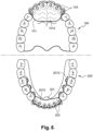
- the aligner 101, 201 is held in position by means of connectors 103, 203 configured to attach against the lingual face 102b, 202b of the teeth 102, 202.
- the aligner 101, 201 engages removably (manually and without an instrument) on the connectors 103, 203 as explained further in the description.
- the connectors 103 can be fixed on all or part of the teeth of a dental arch.
- the connectors 103 are fixed on the lingual face of the central incisors, the lateral incisors and the canines, the aligner 101 being positioned only at the level of these teeth.
- the connectors 203 are fixed on the lingual face of the central incisors, the lateral incisors, the canines, the first premolars, the second premolars and the first molars, the aligner 201 being positioned only at the level of these teeth.
- the connectors 103, 203 may be made of the same polymer material as the aligner 101, 201, or of a separate material, for example metal or ceramic.
- the connectors 103, 203 may be obtained by molding, machining, 3D printing, etc. They are rigid, in the sense that they do not deform when stressed by the aligner.
- all the connectors 103, 203 are advantageously identical in size and shape, regardless of the tooth on which they are fixed and regardless of the dental arch where they are positioned.
- different sizes and/or shapes of connectors may be provided depending on the tooth and/or the dental arch and/or the type of stress to be applied and/or the intensity of the stress to be applied.
- the aligner 101, 201 comprises a gripping member allowing the patient to easily grasp it to disengage it from the connectors 103, 203.
- this gripping member 2012 is in the form of a notch shaped at one or more edges or at each (or only one) distal end of the aligner 201. This notch 2012 allows the patient to slide a nail or a finger therein to disengage the aligner 201.
- the gripping member 2012 may be in another form, for example in the form of a raised element.
- the gripping member 2012 may be shaped at the same time as the aligner 101, 201 or be attached to it.
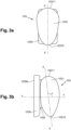
- FIGS. 3a, 3b And 3c illustrate a preferred embodiment of a connector 103 which can be used universally, regardless of the tooth, regardless of the dental arch and regardless of the type and/or intensity of constraint to be applied.
- This connector 103 comprises a base 1030 having a fixing face 1030b adapted to be fixed against the lingual face 102b, 202b of a tooth.
- the base 1030 has a rectangular or substantially rectangular shape , the length of which is between 2 mm and 6 mm, the width is between 1 mm and 3 mm and the thickness is between 0.5 mm and 2 mm.
- the base 1030 may however have other shapes, for example a circular, oval, polygonal shape, etc.
- the fixing face 1030b may be flat, but preferably has a curvature adapted to that of the lingual face 102b, 202b.
- the fixing of the base 1030 on the tooth is carried out by gluing, for example by means of a photo-polymerizable glue .
- the position of connectors 103, 203 is maintained for throughout the treatment so there is no need to change them at each stage.
- the connector 103 also includes a connection head 1301 which is an extension of the base 1030.
- the connection head 1301 is distant from the base 1030, for example distant from 0.5 mm to 2 mm, so that the connector 103 has a collar 1032 connecting said base to said head.
- This collar 1032 can in particular make it possible to receive a chain or an elastic band making it possible to apply a stress to the connector 103, when said chain or said elastic band is attached to another connector, to an anchor screw or to an orthodontic button. This technique can for example be used to pull an included tooth.
- connection head 1031 has an ovoid shape (or water drop or egg shape) having a longitudinal axis of symmetry XX, or main axis.
- this ovoid is included in a parallelepiped envelope whose length is between 2 mm and 6 mm, the width is between 1 mm and 6 mm and the depth is between 1 mm and 6 mm.
- the longitudinal axis of symmetry XX and the normal YY to the fixing face 1030b of the base 1030 advantageously form an angle ⁇ between 10° and 90°, advantageously between 45° and 90° and preferably between 55° and 65°.
- This angulation of the ovoid connection head 1031 allows very precise control of the dental movements, and more particularly the version and the torque.
- the ovoid connection head 1031 has one end 10310 which is more acute than the other opposite end 10311.
- this "pointed" end 10310 is preferentially directed towards the root of said tooth. Good results can however be obtained when the pointed end 10310 is directed towards the occlusal or incisal face of the tooth.
- the pointed end 10310 can be directed towards the distal or mesial face of the tooth.
- Such a connector 103 in particular with an ovoid connection head 1031, having an angulation relative to the base 1030 and whose pointed end 10310 is directed towards the root of the tooth, not only made it possible to move the teeth along any chosen trajectory, with very precise control of the dental movements according to the three orders, but also to precisely adjust the intensity of the constraints applied to the teeth.
- Such a connector 103 can be described as universal insofar as a single shape and a single orientation make it possible to precisely control the six dental movements (version or tipping, egression, ingression, rotation, torque, translation).
- connection head 1031 has an elongated ellipsoid shape whose main axis is the aforementioned longitudinal axis of symmetry XX.
- the two ends 10310 and 10311 are in this case identical and symmetrical.
- connection head 1031 may have an elongated ovoid or ellipsoid shape or another shape and in particular a shape of a sphere, cube, parallelepiped, polyhedron, prism, cone, pyramid, cylinder, etc. It may also consist of a combination of two or more of these different shapes.
- the fixing face 1030b consists of a flat provided directly on the connection head 1031. The latter is then positioned as close as possible to the lingual face of the tooth.
- This design offers greater comfort to the patient since the size (in particular the thickness and/or the height) of the connector 103 is reduced in comparison with that of the Figures 3a, 3b And 3c .
- the connection head 1031 being less overhanging compared to that of the Figures 3a, 3b And 3c , the intensity and/or nature of the constraints applied to the tooth are not the same.
- each aligner 101, 201 comprises reservations 1013, 2013 in which the connectors 103, 203 and more particularly the heads 1031, 2031 fit elastically. To put the aligner 101, 201 in place, it is sufficient to bring the reservations 1013, 2013 opposite the heads 1031, 2031 and to manually push (with the fingers) said reservations onto said heads.
- the reservations 1013, 2013 form cavities (non-opening) in which the heads 1031, 2031 are housed. They are obtained during the shaping of the aligner 101, 201.
- the reservations 1013, 2013 and the flexible strip of the aligner 101, 201 do not exhibit any relative movements between them, in particular when the reservations 1013, 2013 are fitted into the connectors 103, 203, and unlike the solution described in the patent document US 2012/270174 A1 aforementioned.
- the reservations 1013, 2013 have a peripheral lip 10131, 20131 or another undercut shape which deforms during the insertion and removal of the connectors 103, 203. After insertion of the connectors 103, 203, the peripheral lip 10131, 20131 mates with the head 1031, 2031. It is noted here that heads 1031, 2031 in the shape of an ovoid or an ellipsoid ensure easy and painless manual disengagement of the aligner 101, 201, without the risk of tearing off the connectors 103, 203.
- the aligner 101, 201 is mounted and dismounted manually, in the sense that it is not necessary to use specific tools.
- the patient can perform alone and by hand the fitting and dismounting of the aligner 101, 201 on the connectors 103, 203.
- the force allowing the aligner 101, 201 to be removed from the connectors 103, 203 is less than 550 g (grams), advantageously between 50 g and 550 g, and preferably approximately 350 g.
- saliva and successive withdrawals-engagements of the aligner 101, 201 on the connectors 103, 203 make the maneuver easier over time, the reservations 1013, 2013 being able in particular to deform slightly.
- the withdrawal force differs according to the number of connectors 103, 203 engaged with the aligner 101, 201. This force can for example be measured using a tension gauge, a dynamometer, or by any method known to those skilled in the art.
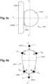
- An ingression movement is obtained by exerting pressure in zone I ( Figure 4a ), at the level of the 10311 end (near the occlusal or incisal face of the tooth), along the long axis of the tooth. This pressure will generate an axial force in the apical direction which tends to push the tooth into its socket.
- an egression movement is obtained by exerting pressure in zone E ( Figure 4a ), at the level of the end 10310 (near the root of the tooth), along the long axis of the tooth. This pressure will generate an axial force in the occlusal direction which tends to force the tooth out of its socket.
- a tipping movement is achieved by exerting pressure in the V11 area and/or in the V12 area ( Figure 4a ). This pressure will cause a rotation of the crown in a mesio -distal direction around a vestibulo-lingual rotation axis. And pressure exerted in the V21 zone and/or in the V22 zone will cause an inverse rotation of the crown in the disto-mesial direction around a vestibulo-lingual axis.
- a torque movement is obtained by exerting pressure in the T11 area and/or in the T12 area ( Figure 4b ). This pressure will cause a rotation of the crown in the vestibulo -lingual direction around a mesio-distal axis . And pressure exerted in the T21 zone and/or in the T22 zone will cause an inverse rotation of the crown, in the lingo- vestibular direction around a mesio-distal axis .
- a rotational movement is obtained by exerting pressure in the R11 zone and/or in the R12 zone ( Figure 4c ). This pressure will cause the tooth to rotate around its major axis, in the disto-mesial direction. And pressure exerted in the R21 zone and/or in the R22 zone will cause the tooth to rotate in the mesio-distal direction around its major axis.
- a translational movement is obtained by exerting pressure in the area L ( Figures 4b and 4c ). This pressure will cause a translation of the crown in the lingo-vestibular direction.
- a similar translation movement is obtained by simultaneously exerting pressure in the R21 and R12 zones (in addition to or in substitution for pressure exerted in the L zone). And pressure exerted simultaneously in the R11 and R22 zones will cause an inverse translation of the tooth in the vestibulo-lingual direction.
- These different movements can be combined by simultaneously exerting pressure in different areas of the head 1031.
- a translational movement and a rotational movement can be combined by simultaneously exerting pressure in the areas L, R11 and R12.
- an egression movement and a version movement can be combined by simultaneously exerting pressure in the areas E and V11. All of these different dental movements can further be amplified and/or adjusted by constraints exerted by the aligner directly on the lingual surface of the teeth. This simultaneously produces distinct stress zones on the connectors and on the lingual surface of the teeth.
- the ovoid or ellipsoid shape of the head 1031 makes it possible to provide an infinite number of stress zones (or thrust zones) which will help to precisely direct the treatment forces exerted by the aligner, to cause one or more desired dental movements.
- the locations of the stress zones chosen by the practitioner also make it possible to adjust the intensity of the treatment forces exerted by the aligner.
- the dental movements, according to the three orders, are thus adjusted and controlled with great precision.
- connection head is an avatar of the tooth to which the connector is attached: the effects of the stresses applied to the head will be directly reflected on the tooth.
- the connectors 103, 203 are fixed to several teeth of an arch. But the aligner 101, 201 will not necessarily apply treatment constraints to all of these teeth. Indeed, only some of these teeth need to be repositioned while others will serve as anchors to hold the aligner 101, 201 in place when it applies the constraints against the tooth(s) to be repositioned.
- the aligner 101, 201 In order for the aligner 101, 201 to be able to exert treatment constraints with sufficient intensity on the connectors 103, 203 on which it fits and/or on the teeth, it must bear against a surface (action-reaction law).
- the surfaces in contact with the aligner are those of the lingual faces 102b, 202b and those of the connection heads 1031, 2031.
- the connectors 103, 203 therefore make it possible to increase the overall contact surface .
- this overall contact surface is much smaller than that of a conventional aligner of the Invisalign ® aligner type which covers, in addition to the lingual faces 102b, 202b, the occlusal, incisal and vestibular faces of the teeth.
- the aligner 101, 201 according to the invention is therefore likely to exert less intense treatment constraints on the connectors 103, 203 and/or on the teeth than Invisalign ® aligners. This can be problematic depending on the nature of the dental movements to be carried out, for example translational or rotational movements.
- one solution is to use an aligner 101, 201 having an increased modulus of elasticity, for example by using a more rigid material and/or by increasing the thickness of said aligners.
- This solution has the disadvantage of being particularly painful and uncomfortable for the patient since the intensity of the constraints can be relatively high locally.
- the aligner 101 has an additional support zone.
- This additional support zone acts as a lever which will increase the intensity of the stresses exerted by the aligner 101, 201.
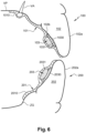
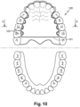
- the aligner 101 has a palatal extension 1010 configured to, in use, come to bear against all or part of the palatal vault VP of the patient.
- the palatal extension 1010 extends beyond the gingival zone, for example by 0.5 cm to 2 cm, to cover all or part of the palatal ridges (inter-canine width for example).
- the surface area of the palatal extension 1010 is between 1 cm 2 and 3 cm 2 .
- the aligner 201 has a gingival extension 2010 configured to, in use, come to bear against a gingival zone ZG of the patient.
- the gingival extension 1010 covers the gingival area over an arch whose length is between 1 cm and 4 cm (e.g.: an inter-canine arch) and up to the muco-gingival junction .
- the surface area of this gingival extension 2010 is for example between 0.5 cm 2 and 2 cm 2 .
- This solution has the advantage of maintaining a relatively thin and flexible aligner 101, 201, which does not generate excessive stress and is therefore particularly comfortable for the patient.
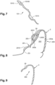
- the palatal extension 1010 is engaged with a VA anchor screw installed in the patient's palate.
- the palatal extension 1010 has a reservation 10100 for this purpose ( Figure 7 ) into which the head of the VA screw fits.
- the aligner 101 thus benefits from an additional anchor point allowing the intensity of the constraints to be increased even further.
- a similar configuration can be envisaged at the level of the gingival extension 2010.
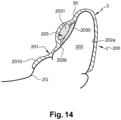
- a removable gutter 3 is profiled to cover the patient's teeth.
- This gutter 3 has a portion 30 which engages on at least a part of the aligner 201 so as to apply to said aligner at least one force tending to constrain it towards the lingual face 202b of the teeth 202 which it covers and which must be moved.
- the gutter 3 is advantageously made of the same material as the aligner 201, and has the same thickness or a substantially equivalent thickness, so that it is flexible.
- This gutter 3 can be placed at the level of the mandibular arch to cover the aligner 201 as well as at the level of the maxillary arch to cover the aligner 101.
- the gutter 3 being adapted to the shape of the aligner 201, there are as many gutters as there are aligners in the treatment sequence.
- the aligner 3 has a receiving cavity 300 which adapts to the teeth, for example to all the teeth of the dental arch on which it is positioned.
- the aligner 3 can thus cover the vestibular face 202a and the occlusal/incisal face of these teeth.
- the aligner 3 also covers their lingual face.
- the portion 30 covers at least a part of said aligner.
- the portion 30 covers the aligner 201 up to the connector 203. However, it could extend beyond, up to the level of the gum. Due to the flexibility of the gutter 3, the portion 30 acts as a clamp on the aligner 201, which will amplify the stress exerted on the connection heads 2031 and/or on the lingual faces 202b of the teeth to be moved.
- the portion 30 does not cover the aligner 201 but is complementary to the latter.
- the teeth with which they cooperate the aligner 201 have: - the majority (for example between 80% and 95%) of their lingual face covered by said aligner; - and the other part of their lingual face, their occlusal/incisal face and their vestibular face covered by the gutter 3.
- the portion 30 can cover a small part of the lingual face, forming a lingual return which extends over a few millimeters (for example from 1 mm to 5 mm) of the occlusal/incisal edge of the tooth.
- the gutter 3 thus acts on the teeth (by applying a stress to them from the vestibular face) but not on the aligner 201.
- This design is particularly advantageous from a manufacturing point of view. Indeed, it is sufficient to design the aligner 201 and the gutter 3 in a single piece (for example by thermoforming) and then to cut said aligner (for example by laser cutting) to separate it from said gutter. These two elements are thus obtained very simply and at lower cost.
- this splint 3 is absolutely not essential, since the lingual aligner 101, 201 gives very good results when used alone.
- the splint 3 is only a simple accessory, which is mainly used at night. It can also be used passively (without constraining the aligner and/or the teeth), as a retention accessory at the end of treatment.
- Orthodontic appliances such as expanders or quad helixes are commonly used to widen a jaw that is too narrow. The force exerted by these appliances allows the palate to widen so that all the teeth can move properly. These appliances are generally restrictive since their installation can be relatively complex. And in the case of a quad helix, activation and adjustment are carried out by the practitioner at each visit. Only the practitioner can modify the appliance, which is particularly restrictive.
- a dental appliance according to an embodiment not covered by the present invention solves these problems.
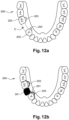
- the connectors 103 are fixed on the lingual surface of the molars and premolars so as to ensure that the hold on the teeth is optimal. However, they can be fixed only on the molars or on other teeth.
- the aligner now takes the form of a palatal plate 101 which covers the palate and which engages in a removable manner (manually and without an instrument) on the connectors 103 as explained previously.
- the plate 101 no longer has the function of aligning the teeth, but of widening the palate (maxillary expansion plate ). Indeed, the connectors 103 and the plate 101 cooperate in such a way as to apply at least one stress on the teeth which tends to spread the palate in a transverse direction.
- the plate 101 is a flexible plate profiled to cover only the lingual face 102b, 202b of the teeth while leaving the other faces of said teeth free. It also covers the palatal vault VP.
- the plate 101 includes reservations into which the connectors 103 fit elastically .
- the flexible plate 101 rests on the palatine vault VP and acts like a spring or a jack.
- the force (shown by the arrows) exerted by the flexible plate 101 on the palatine vault VP and on the connectors 103 and the teeth 102 is oriented in the lingo-vestibular direction, which allows the palate to be spread apart.
- the flexible plate 101 bears against the lingual face of several teeth of a quadrant or half -arch. And possibly teeth which are not provided with a connector 103, such as for example the incisors and the canines on the Figure 10 .
- the flexible plate 101 allows a spreading of the palate in a transverse direction and at the same time in a sagittal direction, i.e. a curved or fan-shaped spreading. This is particularly advantageous when the appliance is worn by a growing child whose normal growth of the maxilla takes place in all directions and not only in the transverse direction. If only a spreading of the palate in a transverse direction is desired, the flexible plate 101 can be configured to constrain only the molars.
- the plate 101 fits and disassembles easily and manually from the connectors 103, the patient can manage his treatment alone. Apart from the installation of the connectors 103, the practitioner does not need to intervene.
- the patient has a series of plate 101 allowing, at each stage, to gradually spread the palate, for example from 0.1 mm to 0.2 mm. Each plate is increasingly wider to widen the palate. There can be between 10 and 100 stages and therefore between 10 and 100 different models of plate 101.
- the plate 101 is adjusted to the intermediate (or final) configuration that the maxillary arch must have at the end of said stage, so that each model of plate 101 exerts stresses on the teeth that tend to widen the palate.
- the flexibility of the plate 101 allows it to deform elastically to the configuration that the arch has at the beginning of the treatment stage. In trying to return to its initial shape (shape memory), the plate 101 exerts stresses on the maxillary arch . The maxillary arch and palate then gradually adjust to the shape of the 101 plate. When the maxillary arch and palate are perfectly adjusted to the shape of a 101 plate, it is changed to move on to the next stage of treatment. The treatment can last from 1 to 6 months and the 101 plates are changed 1 or 2 times per month.
- An implant typically consists of a screw (made of titanium, zirconia, or polymer) inserted into the bone of the maxilla or mandible to create an anchor capable of receiving a dental prosthesis.
- Implant placement is performed in several stages and is usually carried out under anesthesia. During the main surgical stage, the practitioner places the implant in place by screwing it into the bone. During a healing period of several months, the bone reforms around the implant and encloses it.
- an abutment is placed to prepare the gingival flare that will support the prosthesis. The prosthesis is finally placed on the abutment and permanently cemented.
- a dental appliance according to an embodiment not covered by the present invention makes it possible to solve these problems.
- connectors 203 are fixed on the lingual face of the teeth 202 which frame the space E left free at the level of the implantation site. For example, if the implant is placed at the level of the second premolar, the connectors 203 are fixed on the lingual face of the first premolar and the first molar.
- the aligner now comes in the form of a support strip 201 on which a DP dental prosthesis is fixed .
- this prosthesis is made of resin and/or ceramic. It is obtained by molding, machining or 3D printing.
- one or more features disclosed only in one embodiment may be combined with one or more other features disclosed only in another embodiment.
- one or more features disclosed only in one embodiment may be generalized to other embodiments, even if that or those features are described only in combination with other features.
Landscapes
- Health & Medical Sciences (AREA)
- Oral & Maxillofacial Surgery (AREA)
- Dentistry (AREA)
- Epidemiology (AREA)
- Life Sciences & Earth Sciences (AREA)
- Animal Behavior & Ethology (AREA)
- General Health & Medical Sciences (AREA)
- Public Health (AREA)
- Veterinary Medicine (AREA)
- Dental Tools And Instruments Or Auxiliary Dental Instruments (AREA)
- Dental Prosthetics (AREA)
Claims (13)
- Abnehmbare Zahnprothese, umfassend:- einen Zahnausrichter (101, 201), der so eingerichtet ist, dass er mit mindestens einem Zahn (102, 202) eines Zahnbogens (100, 200) eines Patienten zusammenwirkt, um ihn in eine gewünschte Position zu bewegen,- Verbinder (103, 203), die zum Befestigen an Zähnen des Zahnbogens (100, 200) geeignet sind und an denen der Zahnausrichter (101, 201) demontierbar eingerastet wird,dadurch gekennzeichnet, dass:o die Verbinder und der Ausrichter so zusammenwirken, dass mindestens eine Behandlungsbelastung auf mindestens diesen Zahn ausgeübt wird, wenn die Zahnprothese von dem Patienten getragen wird,- der Zahnausrichter (101, 201) aus einem profilierten flexiblen Profilband gebildet ist, um die einzige linguale Seite (102b, 202b) der Zähne abzudecken, wobei die anderen Seiten der Zähne frei bleiben,- die Verbinder (103, 203) so eingerichtet sind, dass sie an der lingualen Seite (102b, 202b) der Zähne befestigt werden,- Aussparungen (1013, 2013), in die die Verbinder (103, 203) elastisch eingreifen, im flexiblen Band so ausgebildet sind, dass die Aussparungen und das flexible Band keine relative Bewegung untereinander aufweisen,- wenn die Aussparungen (1013, 2013) in die Verbinder (103, 203) eingreifen und das flexible Band in Position ist, ermöglicht die Flexibilität des Bands, dass das Band eine oder mehrere Spannungen auf die Verbinder ausübt,- die Aussparungen (1013, 2013) und die Verbinder (103, 203) so eingerichtet sind, dass die Kraft zum Entfernen des Ausrichters aus den Verbindern weniger als 550 g beträgt, so dass die Verbinder von Hand demontierbar in die Aussparungen eingreifen.
- Prothese nach einem der vorhergehenden Ansprüche, wobei jeder Verbinder (103, 203) Folgendes umfasst:- eine Basis (1030, 2030) mit einer Befestigungsfläche (1030b), die geeignet ist, sich an der lingualen Seite (102b, 202b) eines Zahns zu befestigen,- einen Verbindungskopf (1031, 2031) in der Verlängerung der Basis (1030, 2030) und in den eine der Aussparungen (1013, 2013) des Zahnausrichters (101, 201) eingreift.
- Prothese nach Anspruch 2, wobei:- der Verbindungskopf (1031, 2031) eine Ei- oder Ellipsoidform aufweist, die eine Längssymmetrieachse (X-X) aufweist,- die Längssymmetrieachse (X-X) und die Normale zur Befestigungsfläche der Basis bilden einen Winkel (α) zwischen 10° und 90°, günstigerweise zwischen 45° und 90° und vorzugsweise zwischen 55° und 65°.
- Prothese nach einem der Ansprüche 2 oder 3, wobei der Verbindungskopf (1031, 2031) in Eiform ein gegenüberliegendes erstes Ende (10310) und ein zweites Ende (10311) aufweist, wobei das erste Ende spitzer ist als das zweite Ende, wobei das erste Ende im Gebrauch zur Wurzel des Zahns gerichtet ist, an dem der Verbinder (103) befestigt ist.
- Prothese nach einem der Ansprüche 2 bis 4, wobei der Verbindungskopf (1301) von der Basis (1030) entfernt ist, wobei ein Flansch (1032) die Basis mit dem Kopf verbindet.
- Prothese nach Anspruch 1, wobei jeder Verbinder (103, 203) Folgendes umfasst:- einen Verbindungskopf (1031, 2031), in den eine der Aussparungen des Ausrichters eingreift,- eine Befestigungsfläche (1030b), die geeignet ist, sich an der lingualen Seite (102b, 202b) eines Zahns zu befestigen,o die Befestigungsfläche (1030b) besteht aus einer Abflachung, die auf dem Verbindungskopf (1031, 2031) angeordnet ist.
- Prothese nach einem der vorhergehenden Ansprüche, wobei der Ausrichter (101) eine Gaumenerweiterung (1010) aufweist, die so konfiguriert ist, dass sie im Gebrauch den gesamten oder einen Teil des Gaumengewölbes (VP) des Patienten abstützt, wenn der Ausrichter auf Höhe des maxillären Zahnbogens (100) des Patienten positioniert ist.
- Prothese nach einem der vorhergehenden Ansprüche, wobei der Ausrichter (201) eine Gingivaerweiterung (2010) besitzt, die so eingerichtet ist, dass sie im Gebrauch gegen einen Gingivabereich (GV) des Patienten stützt, wenn der Ausrichter auf Höhe des mandibularen Zahnbogens (200) des Patienten positioniert ist.
- Prothese nach einem der vorhergehenden Ansprüche, ferner mit einer flexiblen und abnehmbaren Schiene (3), die so profiliert ist, dass sie im Gebrauch die Zähne des Patienten abdeckt, wobei die Schiene einen Abschnitt (30) aufweist, der in mindestens einen Teil des Ausrichters (201) eingreift, um auf den Ausrichter mindestens eine Kraft auszuüben, die dazu tendiert, ihn in Richtung der lingualen Seite (202b) der zu verschiebenden Zähne zu zwängen.
- Prothese nach einem der Ansprüche 1 bis 8, die ferner eine flexible und abnehmbare Schiene (3) umfasst, die so profiliert ist, dass sie bei Gebrauch die Zähne des Patienten bedeckt, wobei die Schiene einen Abschnitt (30) aufweist, der komplementär zu dem Ausrichter (201) ist, so dass bei Gebrauch die Zähne, mit denen der Ausrichter zusammenwirkt, Folgendes aufweisen:- den größten Teil ihrer lingualen Seite, der von dem Ausrichter bedeckt ist,- den anderen Teil ihrer lingualen Seite, ihre okklusale/inzisale Seite und ihre vestibuläre Seite, die von der Schiene bedeckt sind.
- Prothese nach einem der vorhergehenden Ansprüche, wobei der Ausrichter (101, 201) aus einem Material mit einem Längselastizitätsmodul von weniger als 1000MPa nach der Norm DIN EN ISO 527-2 hergestellt wird.
- Prothese nach einem der Ansprüche 1 bis 11, wobei der Ausrichter (101, 201) aus thermoformbarem Polyurethan besteht.
- Prothese nach einem der Ansprüche 1 bis 11, wobei der Ausrichter (101, 201) Abschnitte oder Bereiche mit unterschiedlichen Elastizitätsmodulen aufweist.
Applications Claiming Priority (2)
| Application Number | Priority Date | Filing Date | Title |
|---|---|---|---|
| FR2108548A FR3125959B1 (fr) | 2021-08-06 | 2021-08-06 | Appareil dentaire amovible |
| PCT/EP2022/070750 WO2023011955A1 (fr) | 2021-08-06 | 2022-07-25 | Appareil dentaire amovible |
Publications (3)
| Publication Number | Publication Date |
|---|---|
| EP4380496A1 EP4380496A1 (de) | 2024-06-12 |
| EP4380496B1 true EP4380496B1 (de) | 2025-05-07 |
| EP4380496C0 EP4380496C0 (de) | 2025-05-07 |
Family
ID=77999145
Family Applications (2)
| Application Number | Title | Priority Date | Filing Date |
|---|---|---|---|
| EP22735835.5A Active EP4380495B1 (de) | 2021-08-06 | 2022-06-17 | Zahnprothesenstützvorrichtung |
| EP22754862.5A Active EP4380496B1 (de) | 2021-08-06 | 2022-07-25 | Abnehmbare zahnärztliche vorrichtung |
Family Applications Before (1)
| Application Number | Title | Priority Date | Filing Date |
|---|---|---|---|
| EP22735835.5A Active EP4380495B1 (de) | 2021-08-06 | 2022-06-17 | Zahnprothesenstützvorrichtung |
Country Status (9)
| Country | Link |
|---|---|
| US (2) | US20250082447A2 (de) |
| EP (2) | EP4380495B1 (de) |
| JP (1) | JP7780846B2 (de) |
| CN (2) | CN117794484A (de) |
| ES (1) | ES3035395T3 (de) |
| FR (1) | FR3125959B1 (de) |
| MX (1) | MX2024001669A (de) |
| PL (1) | PL4380495T3 (de) |
| WO (2) | WO2023011791A1 (de) |
Families Citing this family (3)
| Publication number | Priority date | Publication date | Assignee | Title |
|---|---|---|---|---|
| US20230363863A1 (en) * | 2022-05-13 | 2023-11-16 | SheepMedical Co. Ltd | Systems, methods and devices for providing customized orthodontics devices and techniques |
| EP4458315A1 (de) | 2023-05-03 | 2024-11-06 | Hugo Meley | Orthodontische systeme |
| WO2026057144A1 (en) * | 2024-09-10 | 2026-03-19 | Hugo Meley | Orthodontic systems |
Family Cites Families (21)
| Publication number | Priority date | Publication date | Assignee | Title |
|---|---|---|---|---|
| EP0381871B1 (de) * | 1989-02-10 | 1992-12-23 | Orthodontie Research B.V. | Verfahren zum Anbringen eines orthodontischen Hilfsmittels |
| DE59307179D1 (de) * | 1993-06-10 | 1997-09-25 | Cendres & Metaux Sa | Extracoronales geschiebe |
| US6705863B2 (en) * | 1997-06-20 | 2004-03-16 | Align Technology, Inc. | Attachment devices and methods for a dental appliance |
| WO2003003935A1 (en) * | 2001-07-02 | 2003-01-16 | Young-Kyu Choi | Orthodontic appliance by using a shape memory polymer |
| US6830450B2 (en) * | 2002-04-18 | 2004-12-14 | Align Technology, Inc. | Systems and methods for improved engagement between aligners and teeth |
| US20040067463A1 (en) * | 2002-10-04 | 2004-04-08 | Farel Rosenberg | Computer programmed system for orthodontic correction of malocclusions utilizing snap-on features |
| FR2950522B1 (fr) * | 2009-09-25 | 2012-11-30 | Antoine Meley | Arc de travail orthodontique et systeme de traitement orthodontique comprenant cet arc |
| KR20120053455A (ko) * | 2010-11-17 | 2012-05-25 | 안경숙 | 치아삭제 유도장치 |
| US10588717B2 (en) * | 2015-10-20 | 2020-03-17 | Hankookin, Inc. | Detachable orthodontic bracket and wire system |
| EP3595572B1 (de) * | 2017-03-15 | 2022-06-01 | 3M Innovative Properties Company | Entfernbares kieferorthopädisches gerätesystem |
| GB201720467D0 (en) | 2017-12-08 | 2018-01-24 | Ca Digital Gmbh | Method of producing and deploying orthodontic brackets and attachments |
| US11510755B2 (en) | 2018-02-07 | 2022-11-29 | Ormco Corporation | Custom dental attachment placement appliances and appliance manufacturing methods |
| JP2019154673A (ja) | 2018-03-11 | 2019-09-19 | 宏 重村 | 歯科鋳造用パターンの作製方法 |
| US11937991B2 (en) * | 2018-03-27 | 2024-03-26 | Align Technology, Inc. | Dental attachment placement structure |
| JP2019195424A (ja) | 2018-05-09 | 2019-11-14 | 真有美 山下 | 隣接歯に固定される人工歯、人工歯の固定構造、人工歯の製造方法 |
| CN209548116U (zh) * | 2018-09-19 | 2019-10-29 | 邓允文 | 矫正牙套 |
| US11737856B2 (en) * | 2018-11-15 | 2023-08-29 | 3M Innovative Properties Company | Removable dental appliance with gingival ridges |
| WO2020160051A1 (en) * | 2019-01-28 | 2020-08-06 | Smylio Inc. | Elastic orthodontic appliances, systems, and methods for use |
| JP2021083926A (ja) | 2019-11-29 | 2021-06-03 | 株式会社DSi | 歯列矯正具の提供方法 |
| CN111839765A (zh) * | 2020-07-03 | 2020-10-30 | 广州瑞通生物科技有限公司 | 一种无颌面可摘戴矫治器 |
| EP4337136A4 (de) * | 2021-05-14 | 2025-04-09 | Philip Pramod | Magnetbasierte orthodontische vorrichtung |
-
2021
- 2021-08-06 FR FR2108548A patent/FR3125959B1/fr active Active
-
2022
- 2022-06-17 PL PL22735835.5T patent/PL4380495T3/pl unknown
- 2022-06-17 CN CN202280054816.5A patent/CN117794484A/zh active Pending
- 2022-06-17 WO PCT/EP2022/066601 patent/WO2023011791A1/fr not_active Ceased
- 2022-06-17 JP JP2024507928A patent/JP7780846B2/ja active Active
- 2022-06-17 ES ES22735835T patent/ES3035395T3/es active Active
- 2022-06-17 US US18/681,246 patent/US20250082447A2/en active Pending
- 2022-06-17 MX MX2024001669A patent/MX2024001669A/es unknown
- 2022-06-17 EP EP22735835.5A patent/EP4380495B1/de active Active
- 2022-07-25 WO PCT/EP2022/070750 patent/WO2023011955A1/fr not_active Ceased
- 2022-07-25 US US18/681,257 patent/US20250134626A1/en active Pending
- 2022-07-25 CN CN202280054790.4A patent/CN117794483A/zh active Pending
- 2022-07-25 EP EP22754862.5A patent/EP4380496B1/de active Active
Also Published As
| Publication number | Publication date |
|---|---|
| WO2023011955A1 (fr) | 2023-02-09 |
| JP2024528295A (ja) | 2024-07-26 |
| CN117794484A (zh) | 2024-03-29 |
| MX2024001669A (es) | 2024-02-27 |
| EP4380495C0 (de) | 2025-05-21 |
| FR3125959B1 (fr) | 2024-05-24 |
| PL4380495T3 (pl) | 2025-09-08 |
| US20240325128A1 (en) | 2024-10-03 |
| EP4380495B1 (de) | 2025-05-21 |
| US20250082447A2 (en) | 2025-03-13 |
| EP4380496A1 (de) | 2024-06-12 |
| JP7780846B2 (ja) | 2025-12-05 |
| EP4380495A1 (de) | 2024-06-12 |
| WO2023011791A1 (fr) | 2023-02-09 |
| FR3125959A1 (fr) | 2023-02-10 |
| ES3035395T3 (en) | 2025-09-02 |
| EP4380496C0 (de) | 2025-05-07 |
| US20250134626A1 (en) | 2025-05-01 |
| CN117794483A (zh) | 2024-03-29 |
Similar Documents
| Publication | Publication Date | Title |
|---|---|---|
| EP4380496B1 (de) | Abnehmbare zahnärztliche vorrichtung | |
| EP2958511B1 (de) | Vestibuläre orthodontische vorrichtung | |
| FR2929833A1 (fr) | Procede de conception d'un appareil orthodontique. | |
| EP3439574B1 (de) | Gaumendehnungsvorrichtung | |
| EP3167852A1 (de) | Bissschiene, herstellungsverfahren und orthese, die eine solche bissschiene umfasst | |
| CN112315599A (zh) | 活动式牙合垫矫治器及其制作方法 | |
| EP3817689B1 (de) | Abutment- und einheilungscuff für zahnimplantat | |
| EP3349699B1 (de) | Intraorale vorrichtung zur repositionierung und rehabilitation der zunge | |
| EP4548876A1 (de) | Orthodontische vorrichtung zur palatinalen expansion und distalisierung | |
| FR3053240A1 (fr) | Embase de pilier pour une restauration dentaire | |
| WO2024033402A1 (fr) | Modeleur maxillaire | |
| FR2820308A1 (fr) | Dispositif orthodontique et ses procedes de fabrication | |
| WO2024033401A1 (fr) | Procédé de fabrication d'une gouttière orthodontique | |
| WO2004096076A1 (fr) | Porte-empreinte dentaire equipe de moyens de calage | |
| WO2025017269A1 (fr) | Bracket orthodontique | |
| WO2007135576A1 (fr) | Conformateur buccal | |
| FR2947714A1 (fr) | Support ameliore pour collage sur surface dentaire | |
| WO2024260742A1 (fr) | Dispositif orthodontique | |
| WO2025214618A1 (fr) | Dispositif de protection à usage unique du type languette destiné à se positionner de façon amovible sur une face supérieure d'une lame d'intubation | |
| FR3145862A1 (fr) | Dispositif prothetique dentaire comprenant une piece de liaison deformable | |
| FR2842410A1 (fr) | Ensemble de bridge pour positionner une prothese dentaire | |
| WO2009043998A2 (fr) | Preforme adaptable |
Legal Events
| Date | Code | Title | Description |
|---|---|---|---|
| STAA | Information on the status of an ep patent application or granted ep patent |
Free format text: STATUS: UNKNOWN |
|
| STAA | Information on the status of an ep patent application or granted ep patent |
Free format text: STATUS: THE INTERNATIONAL PUBLICATION HAS BEEN MADE |
|
| PUAI | Public reference made under article 153(3) epc to a published international application that has entered the european phase |
Free format text: ORIGINAL CODE: 0009012 |
|
| STAA | Information on the status of an ep patent application or granted ep patent |
Free format text: STATUS: REQUEST FOR EXAMINATION WAS MADE |
|
| 17P | Request for examination filed |
Effective date: 20240202 |
|
| AK | Designated contracting states |
Kind code of ref document: A1 Designated state(s): AL AT BE BG CH CY CZ DE DK EE ES FI FR GB GR HR HU IE IS IT LI LT LU LV MC MK MT NL NO PL PT RO RS SE SI SK SM TR |
|
| DAV | Request for validation of the european patent (deleted) | ||
| DAX | Request for extension of the european patent (deleted) | ||
| GRAP | Despatch of communication of intention to grant a patent |
Free format text: ORIGINAL CODE: EPIDOSNIGR1 |
|
| STAA | Information on the status of an ep patent application or granted ep patent |
Free format text: STATUS: GRANT OF PATENT IS INTENDED |
|
| INTG | Intention to grant announced |
Effective date: 20241206 |
|
| GRAS | Grant fee paid |
Free format text: ORIGINAL CODE: EPIDOSNIGR3 |
|
| GRAA | (expected) grant |
Free format text: ORIGINAL CODE: 0009210 |
|
| STAA | Information on the status of an ep patent application or granted ep patent |
Free format text: STATUS: THE PATENT HAS BEEN GRANTED |
|
| AK | Designated contracting states |
Kind code of ref document: B1 Designated state(s): AL AT BE BG CH CY CZ DE DK EE ES FI FR GB GR HR HU IE IS IT LI LT LU LV MC MK MT NL NO PL PT RO RS SE SI SK SM TR |
|
| REG | Reference to a national code |
Ref country code: GB Ref legal event code: FG4D Free format text: NOT ENGLISH |
|
| REG | Reference to a national code |
Ref country code: CH Ref legal event code: EP |
|
| REG | Reference to a national code |
Ref country code: DE Ref legal event code: R096 Ref document number: 602022014407 Country of ref document: DE |
|
| REG | Reference to a national code |
Ref country code: IE Ref legal event code: FG4D Free format text: LANGUAGE OF EP DOCUMENT: FRENCH |
|
| U01 | Request for unitary effect filed |
Effective date: 20250507 |
|
| U07 | Unitary effect registered |
Designated state(s): AT BE BG DE DK EE FI FR IT LT LU LV MT NL PT RO SE SI Effective date: 20250514 |
|
| U20 | Renewal fee for the european patent with unitary effect paid |
Year of fee payment: 4 Effective date: 20250717 |
|
| PG25 | Lapsed in a contracting state [announced via postgrant information from national office to epo] |
Ref country code: ES Free format text: LAPSE BECAUSE OF FAILURE TO SUBMIT A TRANSLATION OF THE DESCRIPTION OR TO PAY THE FEE WITHIN THE PRESCRIBED TIME-LIMIT Effective date: 20250507 |
|
| PG25 | Lapsed in a contracting state [announced via postgrant information from national office to epo] |
Ref country code: NO Free format text: LAPSE BECAUSE OF FAILURE TO SUBMIT A TRANSLATION OF THE DESCRIPTION OR TO PAY THE FEE WITHIN THE PRESCRIBED TIME-LIMIT Effective date: 20250807 |
|
| PG25 | Lapsed in a contracting state [announced via postgrant information from national office to epo] |
Ref country code: PL Free format text: LAPSE BECAUSE OF FAILURE TO SUBMIT A TRANSLATION OF THE DESCRIPTION OR TO PAY THE FEE WITHIN THE PRESCRIBED TIME-LIMIT Effective date: 20250507 |
|
| PG25 | Lapsed in a contracting state [announced via postgrant information from national office to epo] |
Ref country code: HR Free format text: LAPSE BECAUSE OF FAILURE TO SUBMIT A TRANSLATION OF THE DESCRIPTION OR TO PAY THE FEE WITHIN THE PRESCRIBED TIME-LIMIT Effective date: 20250507 |
|
| PG25 | Lapsed in a contracting state [announced via postgrant information from national office to epo] |
Ref country code: RS Free format text: LAPSE BECAUSE OF FAILURE TO SUBMIT A TRANSLATION OF THE DESCRIPTION OR TO PAY THE FEE WITHIN THE PRESCRIBED TIME-LIMIT Effective date: 20250807 |
|
| PG25 | Lapsed in a contracting state [announced via postgrant information from national office to epo] |
Ref country code: IS Free format text: LAPSE BECAUSE OF FAILURE TO SUBMIT A TRANSLATION OF THE DESCRIPTION OR TO PAY THE FEE WITHIN THE PRESCRIBED TIME-LIMIT Effective date: 20250907 |
|
| PG25 | Lapsed in a contracting state [announced via postgrant information from national office to epo] |
Ref country code: SM Free format text: LAPSE BECAUSE OF FAILURE TO SUBMIT A TRANSLATION OF THE DESCRIPTION OR TO PAY THE FEE WITHIN THE PRESCRIBED TIME-LIMIT Effective date: 20250507 |
|
| PG25 | Lapsed in a contracting state [announced via postgrant information from national office to epo] |
Ref country code: CZ Free format text: LAPSE BECAUSE OF FAILURE TO SUBMIT A TRANSLATION OF THE DESCRIPTION OR TO PAY THE FEE WITHIN THE PRESCRIBED TIME-LIMIT Effective date: 20250507 |
|
| PG25 | Lapsed in a contracting state [announced via postgrant information from national office to epo] |
Ref country code: SK Free format text: LAPSE BECAUSE OF FAILURE TO SUBMIT A TRANSLATION OF THE DESCRIPTION OR TO PAY THE FEE WITHIN THE PRESCRIBED TIME-LIMIT Effective date: 20250507 |
|
| REG | Reference to a national code |
Ref country code: CH Ref legal event code: H13 Free format text: ST27 STATUS EVENT CODE: U-0-0-H10-H13 (AS PROVIDED BY THE NATIONAL OFFICE) Effective date: 20260224 |
|
| PLBE | No opposition filed within time limit |
Free format text: ORIGINAL CODE: 0009261 |
|
| STAA | Information on the status of an ep patent application or granted ep patent |
Free format text: STATUS: NO OPPOSITION FILED WITHIN TIME LIMIT |
|
| REG | Reference to a national code |
Ref country code: CH Ref legal event code: L10 Free format text: ST27 STATUS EVENT CODE: U-0-0-L10-L00 (AS PROVIDED BY THE NATIONAL OFFICE) Effective date: 20260318 |
|
| 26N | No opposition filed |
Effective date: 20260210 |