EP4380748B1 - Insert de coupe et outil d'usinage - Google Patents
Insert de coupe et outil d'usinage Download PDFInfo
- Publication number
- EP4380748B1 EP4380748B1 EP22758434.9A EP22758434A EP4380748B1 EP 4380748 B1 EP4380748 B1 EP 4380748B1 EP 22758434 A EP22758434 A EP 22758434A EP 4380748 B1 EP4380748 B1 EP 4380748B1
- Authority
- EP
- European Patent Office
- Prior art keywords
- cutting
- cutting insert
- chip
- coolant channel
- insert
- Prior art date
- Legal status (The legal status is an assumption and is not a legal conclusion. Google has not performed a legal analysis and makes no representation as to the accuracy of the status listed.)
- Active
Links
Images
Classifications
-
- B—PERFORMING OPERATIONS; TRANSPORTING
- B23—MACHINE TOOLS; METAL-WORKING NOT OTHERWISE PROVIDED FOR
- B23D—PLANING; SLOTTING; SHEARING; BROACHING; SAWING; FILING; SCRAPING; LIKE OPERATIONS FOR WORKING METAL BY REMOVING MATERIAL, NOT OTHERWISE PROVIDED FOR
- B23D77/00—Reaming tools
- B23D77/006—Reaming tools with means for lubricating or cooling
-
- B—PERFORMING OPERATIONS; TRANSPORTING
- B23—MACHINE TOOLS; METAL-WORKING NOT OTHERWISE PROVIDED FOR
- B23B—TURNING; BORING
- B23B27/00—Tools for turning or boring machines; Tools of a similar kind in general; Accessories therefor
- B23B27/10—Cutting tools with special provision for cooling
-
- B—PERFORMING OPERATIONS; TRANSPORTING
- B23—MACHINE TOOLS; METAL-WORKING NOT OTHERWISE PROVIDED FOR
- B23B—TURNING; BORING
- B23B27/00—Tools for turning or boring machines; Tools of a similar kind in general; Accessories therefor
- B23B27/14—Cutting tools of which the bits or tips or cutting inserts are of special material
- B23B27/141—Specially shaped plate-like cutting inserts, i.e. length greater or equal to width, width greater than or equal to thickness
- B23B27/143—Specially shaped plate-like cutting inserts, i.e. length greater or equal to width, width greater than or equal to thickness characterised by having chip-breakers
-
- B—PERFORMING OPERATIONS; TRANSPORTING
- B23—MACHINE TOOLS; METAL-WORKING NOT OTHERWISE PROVIDED FOR
- B23B—TURNING; BORING
- B23B51/00—Tools for drilling machines
- B23B51/06—Drills with lubricating or cooling equipment
-
- B—PERFORMING OPERATIONS; TRANSPORTING
- B23—MACHINE TOOLS; METAL-WORKING NOT OTHERWISE PROVIDED FOR
- B23C—MILLING
- B23C5/00—Milling-cutters
- B23C5/28—Features relating to lubricating or cooling
-
- B—PERFORMING OPERATIONS; TRANSPORTING
- B23—MACHINE TOOLS; METAL-WORKING NOT OTHERWISE PROVIDED FOR
- B23B—TURNING; BORING
- B23B2250/00—Compensating adverse effects during turning, boring or drilling
- B23B2250/12—Cooling and lubrication
-
- B—PERFORMING OPERATIONS; TRANSPORTING
- B23—MACHINE TOOLS; METAL-WORKING NOT OTHERWISE PROVIDED FOR
- B23D—PLANING; SLOTTING; SHEARING; BROACHING; SAWING; FILING; SCRAPING; LIKE OPERATIONS FOR WORKING METAL BY REMOVING MATERIAL, NOT OTHERWISE PROVIDED FOR
- B23D2277/00—Reaming tools
- B23D2277/20—Number of cutting edges
- B23D2277/204—Five
-
- B—PERFORMING OPERATIONS; TRANSPORTING
- B23—MACHINE TOOLS; METAL-WORKING NOT OTHERWISE PROVIDED FOR
- B23D—PLANING; SLOTTING; SHEARING; BROACHING; SAWING; FILING; SCRAPING; LIKE OPERATIONS FOR WORKING METAL BY REMOVING MATERIAL, NOT OTHERWISE PROVIDED FOR
- B23D2277/00—Reaming tools
- B23D2277/26—Means for breaking chips
-
- B—PERFORMING OPERATIONS; TRANSPORTING
- B23—MACHINE TOOLS; METAL-WORKING NOT OTHERWISE PROVIDED FOR
- B23D—PLANING; SLOTTING; SHEARING; BROACHING; SAWING; FILING; SCRAPING; LIKE OPERATIONS FOR WORKING METAL BY REMOVING MATERIAL, NOT OTHERWISE PROVIDED FOR
- B23D2277/00—Reaming tools
- B23D2277/72—Reaming tools comprising a body having a special profile, i.e. having a special cross section
Definitions
- the present invention relates to a cutting insert for a tool for machining a workpiece. Furthermore, the present invention relates to a tool with such a cutting insert.
- a key issue with such tools is achieving the best possible chip breaking in order to avoid undesirably long chips during machining.
- Good chip breaking properties not only lead to a longer service life for the cutting inserts used in the tools, but also have a positive effect on the surface quality of the machined workpieces.
- coolant lubricants
- coolant channels are often integrated into the tool and/or the cutting insert. These are intended to ensure that the areas of the tool that are subject to the greatest stress receive an adequate supply of coolant at all times during use.
- the geometry provided on the at least one cutting body greatly improves the chip breaking properties of the cutting insert according to the invention.
- the geometric overlap of the coolant channel with the part of the cutting head to which the chip breaking geometry is attached ensures optimal coolant supply. Unlike is often the case with cutting inserts from the prior art, this ensures that the coolant reaches the point on the cutting insert that is crucial for the chip breaking properties. The majority of the coolant emerging from the coolant channel thus hits the chip breaking geometry directly and does not spray over the cutting body of the cutting insert or past it at the side, as is often the case.
- the cutting insert is designed monolithically, i.e. from one piece, so that the clamping section, the cutting head and the boom arm are integrally connected to one another.
- the cantilever arm does not cover the coolant channel in the plan view from the front along the longitudinal axis of the cutting insert.
- the chip-breaking geometry is arranged at a distance from the main cutting edge and a first part of the chip surface runs along the main cutting edge between the chip-breaking geometry and the main cutting edge.
- the cutting body further comprises a secondary cutting edge aligned transversely to the main cutting edge, wherein a second part of the chip surface runs along the secondary cutting edge between the chip-breaking geometry and the secondary cutting edge.
- the term "transverse” describes an alignment of the two cutting edges at an angle other than 0°.
- the two cutting edges (main and secondary cutting edge) are preferably aligned at an acute angle or a right angle to each other. In principle, however, alignment at an obtuse angle to each other is also possible.
- the chip-breaking geometry is completely enclosed by the chip surface both in the direction of the main cutting edge and in the direction of the secondary cutting edge, which leads to the above-mentioned advantages (positive chip angle, improved chip breaking and thus extended service life).
- both the main cutting edge and the secondary cutting edge are each designed to be straight (uncurved).
- the boom arm extends substantially along the longitudinal axis of the cutting insert and the cutting body projects laterally from the cutting head, transversely thereto.
- the diameter of the boom arm or its transverse extension is thinner than the corresponding diameter or the corresponding transverse extension of the cutting head and the clamping section.
- the coolant channel is aligned parallel to the longitudinal axis of the cutting insert.
- the clamping section has on its outer side at least one clamping surface which is aligned parallel to the longitudinal axis of the cutting insert.
- the chip-breaking geometry is designed as a raised geometry that protrudes from the chip surface.
- the chip-breaking geometry protrudes upwards from the chip surface. This further improves the chip-breaking properties.
- the part of the cutting head which has the chip-breaking geometry covers at least 10% of a cross-section of the coolant channel, but at most 80% of the cross-section of the coolant channel (34), when viewed from the front along the longitudinal axis of the cutting insert.
- this overlap enables an optimal supply of coolant/lubricant to at least one cutting body, in particular the chip-breaking geometry and chip surface arranged therein.
- a central axis of the coolant channel is aligned parallel to a surface section of the chip-breaking geometry or lies in a plane with this surface section.
- a cross-section of the coolant channel is non-circular.
- the cross-section of the coolant channel can also be round (circular).
- the coolant jet can be aligned even better onto at least one cutting body.
- a cross-section of the coolant channel is larger at a first end of the coolant channel facing away from the cutting head than at a second end of the coolant channel facing the cutting head.
- the coolant channel can be designed to taper conically, for example.
- the coolant channel can be designed in its interior as a stepped bore with sections of different diameters.
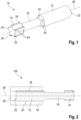
- Fig. 1 and 3-6 show an embodiment of the cutting insert according to the invention in different views.
- the cutting insert is identified in its entirety with the reference number 10.
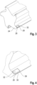
- Fig. 2 shows an embodiment of the tool according to the invention, which has the cutting insert and an associated cutting insert holder.
- the tool is identified in its entirety with the reference number 100.
- the cutting insert 10 shown is a cutting insert for a reaming tool.
- the cutting insert 10 has a clamping section 12, a cutting head 14 and a cantilever arm 16.
- the cutting insert 10 is monolithic. It therefore consists of one piece, with the clamping section 12, the cutting head 14 and the cantilever arm 16 being integrally connected to one another.
- the cutting head 10 is preferably made entirely of hard metal.
- the clamping section 12 serves to clamp the cutting insert 10 in a cutting insert holder 18 (see Fig. 2 ).
- the clamping section is cylindrical.
- the cutting insert receptacle 20 provided in the cutting insert holder 18 also has a cylindrical cross-section.
- the clamping section 12 and the cutting insert receptacle 20 can have any other cross-sectional shapes (eg rectangular, square, oval or complex shaped).
- the cutting insert holder 20 provided in the cutting insert holder 18 is preferably designed as a cup-shaped holder into which the cutting insert 10 can be inserted from the front. Screws or other fastening means can be provided to fix the cutting insert 10 in the cutting insert holder 20.
- the clamping section 12 of the cutting insert 10 preferably rests along its circumference and with its front rear side 22 on corresponding counter-contact surfaces in the cutting insert holder 20. Instead of a full-surface contact, a partial surface contact on the circumference of the clamping section 12 can also be provided.
- the cutting insert holder 18 is in Fig. 2 shown schematically.
- the cutting insert holder 18 can be a conventional tool holder.
- the cutting insert holder 18 can also be part of a machine tool in which the cutting insert 10 is used.
- the cutting insert holder 18 is a clamping chuck directly integrated into the machine tool.
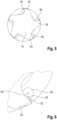
- the cutting head 14 has five cutting bodies 24 which protrude laterally from the cutting head 14. Each of these cutting bodies 24 has a main cutting edge 26 and a secondary cutting edge 28 which is adjacent to the main cutting edge 26 and runs transversely thereto (see Fig. 3-4 ).
- the main cutting edge 26 and the secondary cutting edge 28 are each designed as straight cutting edges in the embodiment shown here.
- a chip surface 30 adjoins the main and secondary edges 26, 28 on the inside, which in particular in the Fig. 4 shown detail is visible.
- a chip-breaking geometry 32 is arranged on the chip surface 30, which in practice is often also referred to as a chip breaker.
- the chip-breaking geometry 32 is designed to break a chip (not shown) lifted off with the main cutting edge 26. This is done essentially by chip deformation. The chip lifted off at the main cutting edge 26 is deflected with the help of the chip-breaking geometry 32, causing it to curve even more and thus forcing it to break.
- the chip-breaking geometry 32 is designed as a raised geometry that protrudes upwards from the chip surface 30. In principle, however, it is also possible to design the chip-breaking geometry as a recessed structure that is incorporated into the chip surface 30.
- the cutting head 14 can also have more or fewer than five of these cutting bodies 24.
- the cutting head 14 of the cutting insert 10 according to the invention can also have only one cutting body 24. This is usually the case when the cutting insert 10 according to the invention is used in a turning tool. It goes without saying that the cutting head 14 is shaped quite differently when used as a turning tool cutting insert than in the exemplary embodiment shown here.
- five coolant channels 34 are arranged in the clamping section 12 - corresponding to the number of cutting bodies 24 - which serve to supply coolant to the cutting head 14.
- a coolant jet emerges from each of these coolant channels 34, which is directed at one of the cutting bodies 24.
- These coolant jets preferably hit the cutting head 14 as free jets, without being deflected or diverted by the extension arm 16.
- the extension arm 16 extends essentially along the longitudinal axis 38 of the cutting insert 10.
- the coolant is supplied to the individual coolant channels 34 via the cutting insert holder 18.
- a coolant channel 36 is provided in the cutting insert holder 18, which feeds all of the coolant channels 34 provided in the cutting insert 10 as a whole.
- several coolant channels 36 can also be provided in the cutting insert holder 18, which individually feed the coolant channels 34 provided in the cutting insert 10. It should also be noted again at this point that if the cutting head is designed with only a single cutting body 24, preferably only one coolant channel is provided inside the clamping section 12.
- Each of the coolant channels 34 preferably runs parallel to the longitudinal axis 38 of the cutting insert 10.
- Each of the coolant channels 34 is designed as a through hole that penetrates the clamping section 12.
- the respective through hole has a contour that is completely closed on the circumference.
- the coolant channels 34 are therefore each closed on the circumference so that no coolant can escape from the side of the clamping section 12 of the cutting insert 10.
- the arrangement of the coolant channels 34 relative to the cutting bodies 24 is discussed in more detail below. This is done using the example of a coolant channel 34 or a cutting head 24.
- the coolant channel 34 is arranged in such a way that in the plan view from the front of the cutting insert, as shown in Fig. 5 and 6 is shown, is at least partially covered by the cutting body 24 assigned to it.
- the coolant channel 34 is covered in particular by the part of the cutting body 24 on which the chip-breaking geometry 32 is arranged.
- the part of the cutting body 24 which has the chip-breaking geometry 32 covers at least 10% of the cross section of the coolant channel 24, but at most 80% of the cross section of the coolant channel 34, when viewed from the front along the longitudinal axis 38 of the cutting insert 10. This ensures optimal cooling and lubrication of the parts of the cutting head 14 used in the machining process.
- the cutting body 24 as well as the chip-breaking geometry 32 arranged thereon are preferably arranged offset radially outwards relative to the coolant channel 34. It is particularly preferred if a central axis 40 of the coolant channel 34 is aligned parallel to a surface section 42 of the chip-breaking geometry.
- the aforementioned surface section 42 which is located on the upper side of the chip-breaking geometry 32, can also be arranged in a plane with the central axis 40 of the coolant channel 34.
Landscapes
- Engineering & Computer Science (AREA)
- Mechanical Engineering (AREA)
- Cutting Tools, Boring Holders, And Turrets (AREA)
- Milling, Broaching, Filing, Reaming, And Others (AREA)
- Drilling Tools (AREA)
Claims (12)
- Dispositif de coupe (10) pour un outil (100) permettant l'usinage par enlèvement de copeaux d'une pièce, dans lequel le dispositif de coupe (10) présente les éléments suivants :- une section de serrage (12) qui présente au moins un canal d'agent de refroidissement (34) conçu sous forme de trou de passage ;- une tête de coupe (14) comportant au moins un corps de coupe (24) qui présente une arête de coupe principale (26) et une face d'attaque (30) adjacente à l'arête de coupe principale (26) ;
et- un bras radial (16) reliant la section de serrage (12) à la tête de coupe (14) et ayant un diamètre plus petit que celui de la section de serrage (12) ;dans lequel le dispositif de coupe (10) est conçu de manière monolithique, de sorte que la section de serrage (12), la tête de coupe (14) et le bras radial (16) sont intégralement reliés les uns aux autres ;caractérisé en ce que le corps de coupe (24) présente une géométrie brise-copeaux (32) qui fait saillie depuis la face d'attaque (30) ou est introduite dans celle-ci, laquelle géométrie est conçue pour briser un copeau détaché par l'arête de coupe principale (26),dans lequel une partie de la tête de coupe (14), laquelle partie présente la géométrie brise-copeaux (32), recouvre le canal d'agent de refroidissement (34), vu dans une vue de dessus, de face, le long d'un axe longitudinal (38) du dispositif de coupe (10), sur au moins 10 % d'une section transversale du canal d'agent de refroidissement, mais au maximum sur 80 % de la section transversale du canal d'agent de refroidissement (34). - Dispositif de coupe selon la revendication 1, dans lequel le bras radial (16) ne recouvre pas le canal d'agent de refroidissement (34) vu dans la vue de dessus, de face, le long de l'axe longitudinal (38) du dispositif de coupe (10).
- Dispositif de coupe selon la revendication 1 ou 2, dans lequel la géométrie brise-copeaux (32) est disposée à distance de l'arête de coupe principale (26) et une première partie de la face d'attaque (30) s'étend le long de l'arête de coupe principale (26) entre la géométrie brise-copeaux (32) et l'arête de coupe principale (26).
- Dispositif de coupe selon la revendication 3, dans lequel le corps de coupe (24) présente en outre une arête de coupe secondaire (28) orientée transversalement à l'arête de coupe principale (26), et dans lequel une seconde partie de la face d'attaque (30) s'étend le long de l'arête de coupe secondaire (28) entre la géométrie brise-copeaux (32) et l'arête de coupe secondaire (28).
- Dispositif de coupe selon la revendication 4, dans lequel l'arête de coupe principale (26) et/ou l'arête de coupe secondaire (28) sont conçues de manière rectiligne.
- Dispositif de coupe selon l'une des revendications 1 à 5, dans lequel le bras radial (16) s'étend sensiblement le long de l'axe longitudinal (38) du dispositif de coupe (10) et le corps de coupe (24) fait saillie transversalement à celui-ci, latéralement depuis la tête de coupe (14).
- Dispositif de coupe selon l'une des revendications 1 à 6, dans lequel le canal d'agent de refroidissement (34) est orienté parallèlement à l'axe longitudinal (38) du dispositif de coupe (10).
- Dispositif de coupe selon l'une des revendications 1 à 7, dans lequel la géométrie brise-copeaux est conçue sous forme de géométrie en relief (32) qui fait saillie depuis la face d'attaque (30).
- Dispositif de coupe selon l'une des revendications 1 à 8, dans lequel un axe central (40) du canal d'agent de refroidissement (34) est orienté parallèlement à une section de surface (42) de la géométrie brise-copeaux (32) ou est dans un plan avec ladite section de surface (42).
- Dispositif de coupe selon l'une des revendications 1 à 9, dans lequel une section transversale du canal d'agent de refroidissement (34) est non circulaire.
- Dispositif de coupe selon l'une des revendications 1 à 10, dans lequel une section transversale du canal d'agent de refroidissement (34) est plus grande au niveau d'une première extrémité du canal d'agent de refroidissement (34) opposée à la tête de coupe (14) qu'au niveau d'une seconde extrémité du canal d'agent de refroidissement (34) tournée vers la tête de coupe (14).
- Outil (100) permettant l'usinage par enlèvement de copeaux d'une pièce, comportant un dispositif de coupe (10) selon l'une des revendications 1 à 11 et un élément de maintien de dispositif de coupe (18) permettant le maintien du dispositif de coupe (10).
Applications Claiming Priority (2)
| Application Number | Priority Date | Filing Date | Title |
|---|---|---|---|
| DE102021120357.0A DE102021120357A1 (de) | 2021-08-05 | 2021-08-05 | Schneideinsatz und werkzeug zur spanenden bearbeitung |
| PCT/EP2022/070951 WO2023011987A1 (fr) | 2021-08-05 | 2022-07-26 | Insert de coupe et outil d'usinage |
Publications (3)
| Publication Number | Publication Date |
|---|---|
| EP4380748A1 EP4380748A1 (fr) | 2024-06-12 |
| EP4380748B1 true EP4380748B1 (fr) | 2024-10-09 |
| EP4380748C0 EP4380748C0 (fr) | 2024-10-09 |
Family
ID=83059180
Family Applications (1)
| Application Number | Title | Priority Date | Filing Date |
|---|---|---|---|
| EP22758434.9A Active EP4380748B1 (fr) | 2021-08-05 | 2022-07-26 | Insert de coupe et outil d'usinage |
Country Status (8)
| Country | Link |
|---|---|
| US (1) | US20240165712A1 (fr) |
| EP (1) | EP4380748B1 (fr) |
| JP (1) | JP7706639B2 (fr) |
| KR (1) | KR20240035620A (fr) |
| CN (1) | CN117794671A (fr) |
| DE (1) | DE102021120357A1 (fr) |
| MX (1) | MX2024001389A (fr) |
| WO (1) | WO2023011987A1 (fr) |
Families Citing this family (1)
| Publication number | Priority date | Publication date | Assignee | Title |
|---|---|---|---|---|
| US20250128333A1 (en) * | 2023-10-20 | 2025-04-24 | Kennametal Inc. | Through coolant clamps for tool holders |
Family Cites Families (38)
| Publication number | Priority date | Publication date | Assignee | Title |
|---|---|---|---|---|
| JPS5269082U (fr) * | 1975-11-18 | 1977-05-23 | ||
| DE8902529U1 (de) * | 1989-03-03 | 1989-08-24 | Hartmetall-Werkzeugfabrik Paul Horn GmbH, 7400 Tübingen | Innendrehmeißel |
| DE4003257A1 (de) | 1990-02-03 | 1991-08-08 | Fette Wilhelm Gmbh | Maschinenwerkzeug, insbesondere maschinengewindebohrer |
| JPH0451306U (fr) * | 1990-08-31 | 1992-04-30 | ||
| ATE136480T1 (de) | 1991-03-13 | 1996-04-15 | Polytool Ag | Reibahle mit auswechselbarem schneidkopf |
| JP2894924B2 (ja) * | 1992-06-17 | 1999-05-24 | 株式会社牧野フライス製作所 | 切削加工方法および装置 |
| JPH0657503U (ja) * | 1992-09-30 | 1994-08-09 | 京セラ株式会社 | ボーリングバー |
| JPH0639305U (ja) * | 1992-10-26 | 1994-05-24 | 三菱マテリアル株式会社 | ボーリングバー |
| DE4320511C2 (de) | 1993-06-21 | 2001-06-13 | Mapal Fab Praezision | Messerplatte für eine Reibahle |
| EP0775031B1 (fr) * | 1994-08-09 | 2002-07-03 | The Edison Materials Technology Center | Usinage cryogenique |
| JP2003071608A (ja) | 2001-08-28 | 2003-03-12 | Mitsubishi Materials Corp | 切削工具 |
| JP4364584B2 (ja) | 2003-08-27 | 2009-11-18 | 株式会社タンガロイ | 切削工具 |
| DE202004008566U1 (de) | 2004-05-26 | 2005-10-13 | Gühring, Jörg, Dr. | Hochleistungsreibahle für MMS |
| JP2007075933A (ja) | 2005-09-13 | 2007-03-29 | Sumitomo Electric Hardmetal Corp | クーラント孔付きボーリングバイト |
| JP2007268695A (ja) | 2006-03-31 | 2007-10-18 | Kyocera Corp | 切削工具およびホルダ |
| DE102007023168A1 (de) | 2007-05-20 | 2008-11-27 | Gühring Ohg | Drehantreibbares spanabhebendes Werkzeug |
| DE102007023167A1 (de) | 2007-05-20 | 2008-11-27 | Gühring Ohg | Spanabhebendes Werkzeug |
| JP5501598B2 (ja) | 2008-10-29 | 2014-05-21 | 京セラ株式会社 | ホルダおよびそれを用いた切削工具並びにそれを用いた切削方法 |
| JP5512386B2 (ja) | 2009-09-25 | 2014-06-04 | Dmg森精機株式会社 | 工具内流路を有する円筒状回転工具およびこの工具による加工方法 |
| DE202010002058U1 (de) * | 2010-02-08 | 2011-06-09 | Johne & Co. Präzisionswerkzeuge GmbH, 46286 | Werkzeug und Werkzeugkopf zum Bearbeiten von Bohrungen und ähnlichen Materialausnehmungen |
| DE102010002669A1 (de) | 2010-03-08 | 2011-09-08 | Gühring Ohg | Drehantreibbares spanabhebendes Werkzeug |
| DE102010021089A1 (de) | 2010-03-25 | 2012-01-12 | Gühring Ohg | Werkzeug mit zentralem Kühlmittelkanal |
| CA2813610A1 (fr) * | 2010-10-04 | 2012-04-12 | Michigan Technological University | Refroidissement par micro-jet d'outils de coupe |
| DE102010051377A1 (de) | 2010-11-16 | 2012-05-16 | Gühring Ohg | Bohrreibahle |
| DE102011082979A1 (de) | 2011-09-19 | 2013-03-21 | Komet Group Gmbh | Reibwerkzeug und Verfahren zu dessen Herstellung |
| JP5952126B2 (ja) | 2012-08-07 | 2016-07-13 | 京セラ株式会社 | インサートおよび切削工具 |
| DE102012111576B4 (de) * | 2012-11-29 | 2022-05-25 | Kennametal Inc. | Schneideinsatz mit Kühlmittelkanal und Schneidwerkzeug mit einem Werkzeughalter und einem solchen Schneideinsatz |
| US9387538B2 (en) | 2013-05-31 | 2016-07-12 | Ntm, Inc. | Tool holder for machine tool, machine tool assembly, and methods |
| SE1350795A1 (sv) * | 2013-06-28 | 2014-12-29 | Sandvik Intellectual Property | Verktyg för spånavskiljande bearbetning jämte skärhållande blad och bytbart skär härför. |
| US20150063931A1 (en) * | 2013-08-30 | 2015-03-05 | Kennametal Inc. | Indexable drill assembly and drill body having coolant supply |
| WO2015056496A1 (fr) | 2013-10-18 | 2015-04-23 | 日本特殊陶業株式会社 | Porte-outil et outil de coupe |
| JP6285326B2 (ja) | 2014-09-05 | 2018-02-28 | 日本特殊陶業株式会社 | バイト用ホルダ及び切削工具 |
| WO2016186217A1 (fr) | 2015-05-21 | 2016-11-24 | 京セラ株式会社 | Support, outil de coupe et son procédé de fabrication de produit découpé |
| WO2017018369A1 (fr) | 2015-07-24 | 2017-02-02 | 京セラ株式会社 | Outil de coupe et procédé de fabrication de pièce usinée utilisant celui-ci |
| DE102016105354B4 (de) * | 2016-03-22 | 2018-03-22 | Hartmetall-Werkzeugfabrik Paul Horn Gmbh | Spanabhebendes Werkzeug |
| DE102017112696A1 (de) * | 2017-06-08 | 2018-12-13 | Gühring KG | Schneidwerkzeug |
| WO2019069924A1 (fr) | 2017-10-06 | 2019-04-11 | 京セラ株式会社 | Outil de coupe et procédé de fabrication d'un article coupé |
| JP2022513767A (ja) | 2019-03-07 | 2022-02-09 | ハルトメタル-ウェルクゾーグファブリック ポール ホーン ゲゼルシャフト ミット ベシュレンクテル ハフツング | ワークピースを機械加工するための切削インサート及び工具 |
-
2021
- 2021-08-05 DE DE102021120357.0A patent/DE102021120357A1/de not_active Withdrawn
-
2022
- 2022-07-26 KR KR1020247006516A patent/KR20240035620A/ko active Pending
- 2022-07-26 EP EP22758434.9A patent/EP4380748B1/fr active Active
- 2022-07-26 MX MX2024001389A patent/MX2024001389A/es unknown
- 2022-07-26 CN CN202280053359.8A patent/CN117794671A/zh active Pending
- 2022-07-26 WO PCT/EP2022/070951 patent/WO2023011987A1/fr not_active Ceased
- 2022-07-26 JP JP2024506730A patent/JP7706639B2/ja active Active
-
2024
- 2024-01-29 US US18/425,456 patent/US20240165712A1/en active Pending
Also Published As
| Publication number | Publication date |
|---|---|
| MX2024001389A (es) | 2024-02-27 |
| JP2024528222A (ja) | 2024-07-26 |
| DE102021120357A1 (de) | 2023-02-09 |
| WO2023011987A1 (fr) | 2023-02-09 |
| EP4380748C0 (fr) | 2024-10-09 |
| JP7706639B2 (ja) | 2025-07-11 |
| CN117794671A (zh) | 2024-03-29 |
| KR20240035620A (ko) | 2024-03-15 |
| US20240165712A1 (en) | 2024-05-23 |
| EP4380748A1 (fr) | 2024-06-12 |
Similar Documents
| Publication | Publication Date | Title |
|---|---|---|
| DE19638177B4 (de) | Werkzeughalter | |
| EP2830799B1 (fr) | Foret de perçage | |
| EP2691202B1 (fr) | Support destiné à l'usinage d'une pièce par enlèvement de copeaux ainsi qu'un outil avec un tel support, avec sortie latéral da'agent de refoidissement | |
| EP2635394B1 (fr) | Foret 3/4 | |
| EP3519130B1 (fr) | Lame de separation de tournage | |
| EP2664400B1 (fr) | Outil de coupe | |
| EP3645201B1 (fr) | Outil de coupe et tête de coupe | |
| EP3694668B1 (fr) | Support pour un outil de rainurage | |
| EP2448704B1 (fr) | Foret pour forage profond | |
| EP2888066A1 (fr) | Foret à une lèvre | |
| EP4380748B1 (fr) | Insert de coupe et outil d'usinage | |
| DE10339518A1 (de) | Bohrwerkzeug mit Wechselschneidplatten sowie Wechselschneidplatten für ein solches Bohrwerkzeug | |
| WO2017174542A1 (fr) | Outil d'usinage par enlèvement de copeaux pour ébavurer des alésages | |
| EP2464479B1 (fr) | Outil de fraisage, en particulier outil de fraisage à fileter | |
| DE19710996C2 (de) | Bohrwerkzeug, insbesondere für Bohrungen in Vollmaterial oder zum Aufbohren | |
| DE3624617C2 (de) | Bohrwerkzeug | |
| DE102009033508B4 (de) | Einlippenbohrer | |
| DE202010015045U1 (de) | Einlippenbohrer | |
| EP1567299B1 (fr) | Outil de coupe de filets | |
| DE202016008998U1 (de) | Reibahlenwerkzeug | |
| DE102021130601B3 (de) | Schneidkopf für ein spanabhebendes Werkzeug | |
| DE202020100455U1 (de) | Werkzeughalter | |
| EP3043938B1 (fr) | Outil de coupe | |
| EP4349512A1 (fr) | Outil d'usinage par enlèvement de copeaux avec d'autres outils d'usinage par enlèvement de copeaux latéraux côté arbre | |
| DE102020100064B3 (de) | Vorrichtung zur Aufnahme eines Zerspanungswerkzeugs |
Legal Events
| Date | Code | Title | Description |
|---|---|---|---|
| STAA | Information on the status of an ep patent application or granted ep patent |
Free format text: STATUS: UNKNOWN |
|
| STAA | Information on the status of an ep patent application or granted ep patent |
Free format text: STATUS: THE INTERNATIONAL PUBLICATION HAS BEEN MADE |
|
| PUAI | Public reference made under article 153(3) epc to a published international application that has entered the european phase |
Free format text: ORIGINAL CODE: 0009012 |
|
| STAA | Information on the status of an ep patent application or granted ep patent |
Free format text: STATUS: REQUEST FOR EXAMINATION WAS MADE |
|
| 17P | Request for examination filed |
Effective date: 20240305 |
|
| AK | Designated contracting states |
Kind code of ref document: A1 Designated state(s): AL AT BE BG CH CY CZ DE DK EE ES FI FR GB GR HR HU IE IS IT LI LT LU LV MC MK MT NL NO PL PT RO RS SE SI SK SM TR |
|
| GRAP | Despatch of communication of intention to grant a patent |
Free format text: ORIGINAL CODE: EPIDOSNIGR1 |
|
| STAA | Information on the status of an ep patent application or granted ep patent |
Free format text: STATUS: GRANT OF PATENT IS INTENDED |
|
| GRAS | Grant fee paid |
Free format text: ORIGINAL CODE: EPIDOSNIGR3 |
|
| INTG | Intention to grant announced |
Effective date: 20240711 |
|
| GRAA | (expected) grant |
Free format text: ORIGINAL CODE: 0009210 |
|
| STAA | Information on the status of an ep patent application or granted ep patent |
Free format text: STATUS: THE PATENT HAS BEEN GRANTED |
|
| AK | Designated contracting states |
Kind code of ref document: B1 Designated state(s): AL AT BE BG CH CY CZ DE DK EE ES FI FR GB GR HR HU IE IS IT LI LT LU LV MC MK MT NL NO PL PT RO RS SE SI SK SM TR |
|
| DAV | Request for validation of the european patent (deleted) | ||
| DAX | Request for extension of the european patent (deleted) | ||
| REG | Reference to a national code |
Ref country code: CH Ref legal event code: EP |
|
| REG | Reference to a national code |
Ref country code: DE Ref legal event code: R096 Ref document number: 502022001869 Country of ref document: DE |
|
| REG | Reference to a national code |
Ref country code: IE Ref legal event code: FG4D Free format text: LANGUAGE OF EP DOCUMENT: GERMAN |
|
| U01 | Request for unitary effect filed |
Effective date: 20241106 |
|
| U07 | Unitary effect registered |
Designated state(s): AT BE BG DE DK EE FI FR IT LT LU LV MT NL PT RO SE SI Effective date: 20241115 |
|
| PG25 | Lapsed in a contracting state [announced via postgrant information from national office to epo] |
Ref country code: IS Free format text: LAPSE BECAUSE OF FAILURE TO SUBMIT A TRANSLATION OF THE DESCRIPTION OR TO PAY THE FEE WITHIN THE PRESCRIBED TIME-LIMIT Effective date: 20250209 Ref country code: HR Free format text: LAPSE BECAUSE OF FAILURE TO SUBMIT A TRANSLATION OF THE DESCRIPTION OR TO PAY THE FEE WITHIN THE PRESCRIBED TIME-LIMIT Effective date: 20241009 |
|
| PG25 | Lapsed in a contracting state [announced via postgrant information from national office to epo] |
Ref country code: ES Free format text: LAPSE BECAUSE OF FAILURE TO SUBMIT A TRANSLATION OF THE DESCRIPTION OR TO PAY THE FEE WITHIN THE PRESCRIBED TIME-LIMIT Effective date: 20241009 |
|
| PG25 | Lapsed in a contracting state [announced via postgrant information from national office to epo] |
Ref country code: NO Free format text: LAPSE BECAUSE OF FAILURE TO SUBMIT A TRANSLATION OF THE DESCRIPTION OR TO PAY THE FEE WITHIN THE PRESCRIBED TIME-LIMIT Effective date: 20250109 |
|
| PG25 | Lapsed in a contracting state [announced via postgrant information from national office to epo] |
Ref country code: GR Free format text: LAPSE BECAUSE OF FAILURE TO SUBMIT A TRANSLATION OF THE DESCRIPTION OR TO PAY THE FEE WITHIN THE PRESCRIBED TIME-LIMIT Effective date: 20250110 |
|
| PG25 | Lapsed in a contracting state [announced via postgrant information from national office to epo] |
Ref country code: PL Free format text: LAPSE BECAUSE OF FAILURE TO SUBMIT A TRANSLATION OF THE DESCRIPTION OR TO PAY THE FEE WITHIN THE PRESCRIBED TIME-LIMIT Effective date: 20241009 |
|
| PG25 | Lapsed in a contracting state [announced via postgrant information from national office to epo] |
Ref country code: RS Free format text: LAPSE BECAUSE OF FAILURE TO SUBMIT A TRANSLATION OF THE DESCRIPTION OR TO PAY THE FEE WITHIN THE PRESCRIBED TIME-LIMIT Effective date: 20250109 |
|
| PG25 | Lapsed in a contracting state [announced via postgrant information from national office to epo] |
Ref country code: SM Free format text: LAPSE BECAUSE OF FAILURE TO SUBMIT A TRANSLATION OF THE DESCRIPTION OR TO PAY THE FEE WITHIN THE PRESCRIBED TIME-LIMIT Effective date: 20241009 |
|
| PG25 | Lapsed in a contracting state [announced via postgrant information from national office to epo] |
Ref country code: SK Free format text: LAPSE BECAUSE OF FAILURE TO SUBMIT A TRANSLATION OF THE DESCRIPTION OR TO PAY THE FEE WITHIN THE PRESCRIBED TIME-LIMIT Effective date: 20241009 |
|
| PLBE | No opposition filed within time limit |
Free format text: ORIGINAL CODE: 0009261 |
|
| STAA | Information on the status of an ep patent application or granted ep patent |
Free format text: STATUS: NO OPPOSITION FILED WITHIN TIME LIMIT |
|
| U20 | Renewal fee for the european patent with unitary effect paid |
Year of fee payment: 4 Effective date: 20250730 |
|
| 26N | No opposition filed |
Effective date: 20250710 |
|
| PGFP | Annual fee paid to national office [announced via postgrant information from national office to epo] |
Ref country code: CH Payment date: 20250801 Year of fee payment: 4 |
|
| PGFP | Annual fee paid to national office [announced via postgrant information from national office to epo] |
Ref country code: CZ Payment date: 20250718 Year of fee payment: 4 |