WO2019069924A1 - Outil de coupe et procédé de fabrication d'un article coupé - Google Patents
Outil de coupe et procédé de fabrication d'un article coupé Download PDFInfo
- Publication number
- WO2019069924A1 WO2019069924A1 PCT/JP2018/036880 JP2018036880W WO2019069924A1 WO 2019069924 A1 WO2019069924 A1 WO 2019069924A1 JP 2018036880 W JP2018036880 W JP 2018036880W WO 2019069924 A1 WO2019069924 A1 WO 2019069924A1
- Authority
- WO
- WIPO (PCT)
- Prior art keywords
- flow path
- cutting tool
- outlet
- central axis
- cutting
- Prior art date
- Legal status (The legal status is an assumption and is not a legal conclusion. Google has not performed a legal analysis and makes no representation as to the accuracy of the status listed.)
- Ceased
Links
Images









Classifications
-
- B—PERFORMING OPERATIONS; TRANSPORTING
- B23—MACHINE TOOLS; METAL-WORKING NOT OTHERWISE PROVIDED FOR
- B23B—TURNING; BORING
- B23B27/00—Tools for turning or boring machines; Tools of a similar kind in general; Accessories therefor
- B23B27/10—Cutting tools with special provision for cooling
-
- B—PERFORMING OPERATIONS; TRANSPORTING
- B23—MACHINE TOOLS; METAL-WORKING NOT OTHERWISE PROVIDED FOR
- B23B—TURNING; BORING
- B23B2200/00—Details of cutting inserts
- B23B2200/12—Side or flank surfaces
- B23B2200/123—Side or flank surfaces curved
-
- B—PERFORMING OPERATIONS; TRANSPORTING
- B23—MACHINE TOOLS; METAL-WORKING NOT OTHERWISE PROVIDED FOR
- B23B—TURNING; BORING
- B23B2220/00—Details of turning, boring or drilling processes
- B23B2220/12—Grooving
- B23B2220/123—Producing internal grooves
-
- B—PERFORMING OPERATIONS; TRANSPORTING
- B23—MACHINE TOOLS; METAL-WORKING NOT OTHERWISE PROVIDED FOR
- B23B—TURNING; BORING
- B23B27/00—Tools for turning or boring machines; Tools of a similar kind in general; Accessories therefor
- B23B27/007—Tools for turning or boring machines; Tools of a similar kind in general; Accessories therefor for internal turning
-
- B—PERFORMING OPERATIONS; TRANSPORTING
- B23—MACHINE TOOLS; METAL-WORKING NOT OTHERWISE PROVIDED FOR
- B23Q—DETAILS, COMPONENTS, OR ACCESSORIES FOR MACHINE TOOLS, e.g. ARRANGEMENTS FOR COPYING OR CONTROLLING; MACHINE TOOLS IN GENERAL CHARACTERISED BY THE CONSTRUCTION OF PARTICULAR DETAILS OR COMPONENTS; COMBINATIONS OR ASSOCIATIONS OF METAL-WORKING MACHINES, NOT DIRECTED TO A PARTICULAR RESULT
- B23Q11/00—Accessories fitted to machine tools for keeping tools or parts of the machine in good working condition or for cooling work; Safety devices specially combined with or arranged in, or specially adapted for use in connection with, machine tools
- B23Q11/10—Arrangements for cooling or lubricating tools or work
Definitions
- This aspect generally relates to a cutting insert used in cutting.
- the present invention relates to a cutting tool used in internal diameter machining. More specifically, it relates to a boring bit.
- Patent Document 1 Japanese Patent Application Laid-Open No. 2007-75933
- Patent Document 2 Japanese Patent Application Laid-Open No. 2001-87906
- Patent Document 1 describes a cutting tool in which an injection hole of a coolant hole provided in the interior of a shank is inclined toward a cutting edge in a plan view. Further, Patent Document 2 discloses a cutting tool having a first nozzle for blowing a cooling fluid (coolant) toward the upper side surface of the insert, and a second nozzle for blowing a coolant toward chips. Is described.
- a cutting tool has a rod-shaped body extending along a central axis from a first end to a second end.
- the main body has a cutting blade, a first flow path, a second flow path, a third flow path, and a fourth flow path.
- the cutting blade is positioned to project laterally on the side of the first end of the main body.
- the first channel is located along the central axis and has an inlet.
- the second flow passage is located along the central axis from the first flow passage to the first end, and has a smaller inner diameter than the first flow passage.
- the third flow path is connected to the first flow path and has a first outlet.
- the fourth flow path is connected to the second flow path and has a second outlet. The first outlet is located farther from the virtual plane including the central axis and the cutting edge than the second outlet.
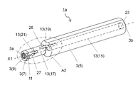
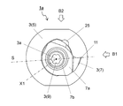
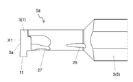
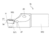
- FIG. 5 It is a perspective view showing one cutting tool of an embodiment. It is an enlarged view in area
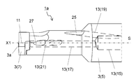
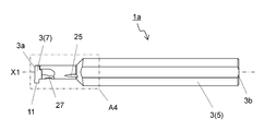
- FIG. It is the figure which looked at the flow path in the cutting tool shown in FIG. It is a side view showing one cutting tool of an embodiment. It is an enlarged view in area
- the cutting tool described in Patent Document 2 is a tool used when cutting the outer diameter of a work material. Therefore, in the cutting tool described in Patent Document 2, the position of the outlet in the first nozzle and the second nozzle and the degree of freedom in the extending direction of the first nozzle and the second nozzle are high.
- the coolant hole is used since it is inserted in the hole of the work material.
- the degree of freedom of the position of the outlet and the extending direction of the coolant hole is low. Therefore, it has been difficult to discharge chips efficiently using a coolant and to efficiently cool the cutting edge.
- the cutting tool of a plurality of embodiments is explained in detail using a drawing, respectively.
- the drawings referred to in the following simply show only the main members necessary for describing each embodiment.
- the cutting tool may comprise any component not shown in the figures to which it refers.
- the dimensions of the members in the respective drawings do not faithfully represent the dimensions and dimensional ratios of actual component members.
- ⁇ Cutting tool> As one cutting tool of an embodiment, it illustrates about cutting tool 1a for internal diameter grooving processing.
- the cutting tool 1a of an example shown in FIG. 1 has the rod-shaped main-body part 3 extended from the 1st end 3a to the 2nd end 3b along the central axis X1.
- the first end 3a is referred to as the "tip” and the second end 3b is referred to as the "rear end”.
- the main body portion 3 may have any configuration as long as it extends from the first end 3a to the second end 3b, and may be, for example, a cylindrical shape or a polygonal prism shape.
- Body part 3 may be constituted by one member, and may be constituted by a plurality of members.
- a cutting tool 1a having a body portion 3 constituted by one member is generally called a solid type.
- the main-body part 3 of an example shown in FIG. 1 is comprised by the several member. Specifically, the main body 3 in the example shown in FIG. 2 includes the holder 5, the insert 7, and the fixing member 9.
- the holder 5 may have a bar shape extending along the central axis X1 from the first end 3a to the second end 3b. At this time, the outer diameter of the holder 5 may be constant or may be changed. In the example shown in FIG. 1, the holder 5 is located on the side of the first end 3a and has a small diameter portion 5a having a relatively small outer diameter, and the holder 5 is located on the second end 3b side relative to the small diameter portion 5a. It is comprised by the large diameter part 5b with a relatively large outer diameter.
- the insert 7 may be located on the side of the first end 3 a of the holder 5. In the example shown in FIG. 2, the insert 7 is in contact with the end face of the holder 5 on the side of the first end 3 a.
- the size of the holder 5 may be appropriately set according to the size of the work material.
- the length in the direction along the central axis X1 of the holder 5 is set to, for example, about 60 mm or more and 200 mm or less. Further, the width in the direction orthogonal to the central axis X1 is set to, for example, about 6 mm or more and 50 mm or less.
- the end surface 7 a and the surface opposite to the end surface 7 a in the insert 7 may have a substantially circular disk shape. Further, as in the example shown in FIG. 2, the insert 7 may have an end surface 7 a and a through hole 7 b opened in a surface opposite to the end surface 7 a.
- the shape of the insert 7 is not limited to the structure shown in FIG.
- the insert 7 may have a polygonal plate shape in which the end surface 7a and the surface opposite to the end surface 7a have a substantially polygonal shape.
- the insert 7 may be in the shape of a bar extending in the direction orthogonal to the central axis X1 of the holder 5.
- Such a rod-shaped insert 7 may be called a dockbone type.
- cemented carbide As a material of a member which constitutes insert 7, cemented carbide, a cermet, etc. are mentioned, for example.
- the composition of the cemented carbide include WC-Co, WC-TiC-Co, and WC-TiC-TaC-Co.
- WC-Co is produced by adding a powder of cobalt (Co) to tungsten carbide (WC) and sintering it.
- WC-TiC-Co is obtained by adding titanium carbide (TiC) to WC-Co.
- WC-TiC-TaC-Co is obtained by adding tantalum carbide (TaC) to WC-TiC-Co.
- cermet is a sintered composite material in which a ceramic component is compounded with a metal.
- a ceramic component is compounded with a metal.
- a titanium compound such as titanium carbide (TiC) or titanium nitride (TiN) as a main component is mentioned.
- the fixing member 9 is a member for fixing the insert 7 to the holder 5.
- the fixing member 9 is a screw 9.
- the fixing member 9 is not limited to the screw 9 and may be, for example, a clamp member.
- the insert 7 has the through hole 7b as described above, and the holder 5 has a screw hole (not shown) at a position corresponding to the through hole 7b.
- the insert 7 can be fixed to the holder 5 by inserting the screw 9 into the through hole 7 b of the insert 7 and fixing the screw 9 to the screw hole of the holder 5.
- the through hole 7b and the screw hole extend in the direction along the central axis X1.
- the main body 3 has a cutting edge 11 positioned to project laterally on the side of the first end 3a. It is possible to perform cutting by bringing the cutting blade 11 into contact with the work material.
- the cutting edge 11 is located farthest from the central axis X ⁇ b> 1 on the first end 3 a side of the main body 3. Since the cutting blade 11 protrudes laterally, only the vicinity of the cutting blade 11 in the main body 3 can be brought into contact with the work material.
- the insert 7 in the main body 3 has the cutting edge 11.
- the main-body part 3 has the flow path 13 located inside.
- the flow path 13 can function as a portion through which the coolant flows when the cutting tool 1 a is used.
- the holder 5 in the main body 3 has a flow path 13.
- the flow path 13 in the example shown in FIG. 3 has a first flow path 15, a second flow path 17, a third flow path 19 and a fourth flow path 21.
- the first flow passage 15 is located along the central axis X1 and has a coolant inlet 23.
- the first flow path 15 is located on the side of the second end 3 b of the main body 3 and extends linearly along the central axis X 1.
- the coolant inlet 23 is located at the end face of the main body 3 on the second end 3 b side.
- the position of the inflow port 23 of a coolant is not limited to said end surface, For example, you may be located in the outer peripheral surface of the main-body part 3.
- the second flow path 17 extends from the first flow path 15 toward the first end 3a, and is located along the central axis X1.
- the second flow path 17 is located on the side of the first end 3 a of the main body 3 compared to the first flow path 15, and extends linearly along the central axis X1.
- the inner diameter of the second flow path 17 in the example shown in FIG. 4 is smaller than the inner diameter of the first flow path 15. As described above, since the inner diameter of the second flow passage 17 is smaller than the inner diameter of the first flow passage 15, the fluid pressure of the coolant injected from the first outlet 25 and the second outlet 27 described later can be increased. it can.
- the third flow passage 19 is connected to the first flow passage 15 and has a first outlet 25.
- the first outlet 25 in the example shown in FIG. 4 is located on the outer peripheral surface of the main body 3.
- the third flow path 19 may extend in a straight line.
- the first outlet 25 can function as an area for injecting the coolant toward the chips generated by the cutting edge 11.
- the holder 5 is constituted by the small diameter portion 5a and the large diameter portion 5b as in the example shown in FIG. 2, even if the first outlet 25 is positioned to straddle the small diameter portion 5a and the large diameter portion 5b. Good.
- the fourth flow passage 21 is connected to the second flow passage 17 and has a second outlet 27.
- the second outlet 27 in the example shown in FIG. 4 is located on the outer peripheral surface of the main body 3. As an example shown in FIG. 4, the fourth flow path 21 may extend linearly.
- the second outlet 27 can function as a region for injecting the coolant toward the cutting edge 11.
- the first outlet 25 is located farther from the virtual plane S including the central axis X 1 and the cutting edge 11 than the second outlet 27.
- the virtual plane S is a plane including the central axis X1 and the cutting edge 11 as shown in FIG. 5, and the cutting edge 11 is overlapped with the central axis X1 as shown in FIGS. 7 and 8. In the state, the central axis X1 and the virtual plane S are shown to overlap.
- first outlet 25 and the second outlet 27 have the above-described positional relationship, it is possible to discharge chips efficiently and to cool the cutting edge 11 efficiently. This is because the coolant injected from the first outlet 25 when injecting the coolant from the first outlet 25 toward chips and injecting the coolant from the second outlet 27 toward the cutting edge 11 This is because it is difficult to collide with the coolant injected from the 2 outlet 27.
- the coolant injected from the first outlet 25 is more unlikely to collide with the coolant injected from the second outlet 27.
- the second outlet 27 is also injected from the first outlet 25 when the second outlet 27 is farther from the central axis X1 than the first outlet 25. It is more difficult for the coolant to collide with the coolant injected from the second outlet 27.
- the coolant is supplied from the inlet 23 to the first flow path 15.
- the coolant supplied to the first flow path 15 is discharged from the first outlet 25 through the third flow path 19.
- the coolant supplied to the first flow path 15 is discharged from the second outlet 27 through the second flow path 17 and the fourth flow path 21.
- the coolant may be supplied not only from the inflow port 23 but also from a point other than the inflow port 23. Further, the coolant may be supplied not only from the first outlet 25 and the second outlet 27 but also from a point other than these outlets.
- the coolant is made of, for example, a water insoluble oil agent or a water soluble oil agent, and can be appropriately selected and used according to the material of the material to be cut.
- a water insoluble oil agent for example, oil type, inactive extreme pressure type and active extreme pressure type cutting oil can be mentioned.
- the water-soluble oil includes, for example, cutting oils such as emulsions, solutions and solutions.
- the coolant is not limited to a liquid, and may be a gas such as an inert gas.
- the shape of the flow path 13 is not particularly limited as long as the coolant can flow.
- the first flow path 15, the second flow path 17, the third flow path 19, and the fourth flow path 21 in one of the embodiments each have a circular cross section orthogonal to the flowing direction of the coolant, for example,
- the shape of the flow path 13 in the above-mentioned cross section may be elliptical or polygonal.
- the inner diameter of the flow path 13 is, for example, 1 mm or more and 10 mm or less.
- the flow path 13 can be formed by performing hole processing on a member to be the main body portion 3 using a drill or the like. A portion of the hole formed by drilling may not function as the flow path 13 may be closed by a seal member (not shown) so that the coolant does not leak.
- a seal member As a sealing member, solder, a resin member, and a screw member are mentioned, for example.
- the inner diameter of the second flow path 17 is smaller than the inner diameter of the first flow path 15. Therefore, the first outlet 25 of the third flow passage 19 connected to the first flow passage 15 has a center axis X1 and a central axis X1 more than the second discharge outlet 27 of the fourth flow passage 21 connected to the second flow passage 17. It is configured to be easily located apart from the virtual plane S including the cutting edge 11. Thereby, the degrees of freedom of the extending direction of the third flow path 19 and the fourth flow path 21 and the positions of the first outlet 25 and the second outlet 27 are increased.
- the inner diameter of the fourth flow passage 21 in the example shown in FIG. 3 is smaller than the inner diameter of the second flow passage 17.
- the injection pressure of the coolant injected from the second outlet 27 can be increased.
- the second outlet 27 opens toward the cutting edge 11 in order to cause the coolant to flow out toward the cutting edge 11.
- a virtual extension line L1 of the fourth flow path 21 extending in a straight line intersects the cutting edge 11.
- the first outlet 25 in order to cause the coolant to flow out toward the chips generated by the cutting edge 11, the first outlet 25 is moved to a position away from the cutting edge 11 on the virtual plane S. It is open. Specifically, in the example shown in FIG. 7 and FIG. 8, the first outlet 25 opens upward of the cutting edge 11.
- the coolant injected from the first outlet 25 is stably applied to the chips generated by the cutting edge 11 and extending upward of the cutting edge 11. be able to. Therefore, chips can be discharged better.
- the first outlet 25 is located farther from the virtual plane S than the second outlet 27.
- the third channel 19 is the fourth channel. 21 may be located away from the virtual plane S.
- the third flow passage 19 and the fourth flow passage 21 have the above-described positional relationship, the extending direction of the third flow passage 19 and the fourth flow passage 21 and the positions of the first outlet 25 and the second outlet 27 The degree of freedom is even higher. Therefore, it is possible to cool the cutting blade 11 more efficiently and to discharge the chips better.
- the extending direction of the third flow path 19 is not limited to a specific direction.
- the third flow path 19 may extend away from the virtual plane S as it is separated from the first flow path 15.
- the third flow path 19 in the example shown in FIG. 8 extends upward and away from the virtual plane S as the distance from the first flow path 15 is increased.
- the coolant passing through the third flow path 19 is injected from the first outlet 25 toward chips generated by the cutting edge 11.
- chips are discharged away from the cutting edge 11 by the coolant injected from the first outlet 25. easy. Therefore, the chip dischargeability is further enhanced.
- the extending direction of the fourth flow path 21 is not limited to a specific direction.
- the fourth flow path 21 extends parallel to the virtual plane S. It may extend along the imaginary plane S as in the fourth flow path 21 of the example shown in FIG. 8.
- the coolant passing through the fourth flow path 21 is injected from the second outlet 27 toward the cutting edge 11.
- the fourth flow path 21 extends in parallel to the virtual plane S, the length from the second outlet 27 to the cutting edge 11 is shortened. Therefore, the coolant injected from the second outlet 27 can be efficiently applied to the cutting edge 11. Therefore, the cutting blade 11 can be cooled more efficiently.
- the second outlet 27 may be located closer to the first end 3a than the first outlet 25.
- the length from the second outlet 27 to the cutting edge 11 can be shortened. Therefore, as described above, the coolant injected from the second outlet 27 can be efficiently applied to the cutting edge 11.
- the coolant injected from the first outlet 25 can be easily dispersed widely. Therefore, it is easy to discharge stably the chips generated by the cutting blade 11.
- the angle formed by the fourth flow path 21 and the central axis X1 (hereinafter referred to as the second inclination angle ⁇ 2) is the angle formed by the third flow path 19 and the central axis X1 ( Hereinafter, it may be larger than the first inclination angle ⁇ 1).
- the second inclination angle ⁇ 2 When the second inclination angle ⁇ 2 is relatively large, it is easy to inject the coolant from the second outlet 27 toward the cutting edge 11, and the length from the second outlet 27 to the cutting edge 11 is further shortened. it can. Further, when the first inclination angle ⁇ 1 is relatively small, it is possible to reduce the loss of fluid pressure when the coolant flows from the first flow passage 15 to the third flow passage 19. Therefore, it is easy to discharge chips more stably by the coolant injected from the second outlet 27.
- the cutting tool 1a for internal diameter processing is not limited to the cutting tool for internal diameter grooving processing, and a boring tool etc. are mentioned as a cutting tool for internal diameter processing, for example. Therefore, a boring tool for inner diameter machining is illustrated as one cutting tool 1b of the embodiment.
- FIGS. 12 to 17 correspond to FIGS. 6 to 11, respectively.
- differences between the cutting tool 1b and the cutting tool 1a will be mainly described, and the detailed description may be omitted for the point having the same configuration as the cutting tool 1a.
- the cutting tool 1b shown in FIGS. 12 and 15 has a rod-shaped main body 3 extending along the central axis X1 from the first end 3a to the second end 3b.
- the main body 3 in the example shown in FIG. 12 is configured of the holder 5, the insert 7, and the fixing member 9.
- a pocket is located on the side of the first end 3 a of the holder 5.
- the holder 5 has one pocket.
- a recess is located on the side of the first end 3 a of the holder 5, and a pocket is configured by the recess.
- the pocket is an area where the insert 7 is located.
- the insert 7 of the example shown in FIG. 2 has a disk shape
- the insert 7 of the example shown in FIG. 13 has a polygonal plate shape.
- the insert 7 of the example shown in FIG. 2 has a through hole 7 b as in the case of the insert 7 of the example shown in FIG. 13.
- the through-hole 7b and the screw hole are extended in the direction along the central axis X1
- the through-hole 7b and the screw hole are central axes It extends in the direction orthogonal to X1.
- the cutting tool 1b of the example shown in FIG. 13 is the first flow path 15, the second flow path 17, the third flow path 19 and the fourth flow path as the flow path 13 similarly to the cutting tool 1a of the example shown in FIG. It has 21.
- the 1st outflow port 25 which the 3rd flow path 19 has contains the central axis X1 and the cutting edge 11 rather than the 2nd outflow port 27 which the 4th flow path 21 has. It is located away from the plane S. Therefore, also in the cutting tool 1b of one example shown in FIGS. 15 to 17, it is possible to cool the cutting edge 11 efficiently and to discharge the chips favorably.
- the structure demonstrated about the cutting tool 1a is applicable suitably to the cutting tool 1b.
- the third flow path 19 may extend away from the virtual plane S as it is separated from the first flow path 15, and the fourth flow path 21 may It may extend parallel to the virtual plane S.
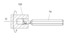
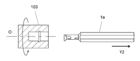
- the method of manufacturing the machined product 103 according to one of the embodiments includes the following steps (1) to (4).
- the cutting tool 1a is moved in the direction of the arrow Y1 to make the cutting tool 1a relatively approach the rotating workpiece 101.
- the cutting tool 1 a is brought into contact with the rotating work material 101.
- the cutting material 101 is cut by bringing the cutting edge of the cutting tool 1 a into contact with the material to be cut 101.
- the work material 101 may be cut while the coolant flows out from the first outlet and the second outlet.
- the cutting tool 1a is separated from the work material 101 by moving the cutting tool 1a in the direction of the arrow Y2 to obtain a machined product 103.
- the cutting tool 1a since the cutting tool 1a is used, it is possible to cool the cutting edge efficiently and to discharge the chips favorably.
- the work material 101 may be brought close to the cutting tool 1a.
- the work material 101 may be moved away from the cutting tool 1a.
- the process of rotating the work material 101 may be maintained, and the process of bringing the cutting blade into contact with different portions of the work material 101 may be repeated.
- this indication is not limited to the embodiment mentioned above, It may be arbitrary unless it deviates from the gist of this indication. Needless to say, it can be done.
Landscapes
- Engineering & Computer Science (AREA)
- Mechanical Engineering (AREA)
- Cutting Tools, Boring Holders, And Turrets (AREA)
- Drilling And Boring (AREA)
Abstract
Priority Applications (4)
| Application Number | Priority Date | Filing Date | Title |
|---|---|---|---|
| US16/652,853 US11370032B2 (en) | 2017-10-06 | 2018-10-02 | Cutting tool and method for manufacturing machined product |
| JP2019546733A JP7104055B2 (ja) | 2017-10-06 | 2018-10-02 | 切削工具及び切削加工物の製造方法 |
| DE112018004430.0T DE112018004430B4 (de) | 2017-10-06 | 2018-10-02 | Schneidwerkzeug und verfahren zur herstellung eines maschinell bearbeiteten produkts |
| CN201880065126.3A CN111182987B (zh) | 2017-10-06 | 2018-10-02 | 切削刀具以及切削加工物的制造方法 |
Applications Claiming Priority (2)
| Application Number | Priority Date | Filing Date | Title |
|---|---|---|---|
| JP2017195605 | 2017-10-06 | ||
| JP2017-195605 | 2017-10-06 |
Publications (1)
| Publication Number | Publication Date |
|---|---|
| WO2019069924A1 true WO2019069924A1 (fr) | 2019-04-11 |
Family
ID=65994936
Family Applications (1)
| Application Number | Title | Priority Date | Filing Date |
|---|---|---|---|
| PCT/JP2018/036880 Ceased WO2019069924A1 (fr) | 2017-10-06 | 2018-10-02 | Outil de coupe et procédé de fabrication d'un article coupé |
Country Status (5)
| Country | Link |
|---|---|
| US (1) | US11370032B2 (fr) |
| JP (1) | JP7104055B2 (fr) |
| CN (1) | CN111182987B (fr) |
| DE (1) | DE112018004430B4 (fr) |
| WO (1) | WO2019069924A1 (fr) |
Cited By (6)
| Publication number | Priority date | Publication date | Assignee | Title |
|---|---|---|---|---|
| WO2022085760A1 (fr) * | 2020-10-22 | 2022-04-28 | 京セラ株式会社 | Support, outil de coupe et procédé de fabrication de produit découpé |
| JP2023520108A (ja) * | 2021-04-27 | 2023-05-16 | 住友電工ハードメタル株式会社 | ボーリング工具および切削インサート |
| JP7312387B1 (ja) | 2022-12-08 | 2023-07-21 | 株式会社タンガロイ | 刃先交換式切削工具および切削インサート |
| JP7449504B1 (ja) | 2023-11-02 | 2024-03-14 | 株式会社タンガロイ | 切削工具とそのボディ |
| JP2024528222A (ja) * | 2021-08-05 | 2024-07-26 | ハルトメタル-ウェルクゾーグファブリック ポール ホーン ゲゼルシャフト ミット ベシュレンクテル ハフツング | 切削インサート及び機械加工用工具 |
| EP4599964A1 (fr) | 2024-02-06 | 2025-08-13 | Tungaloy Corporation | Corps d'outil de coupe et outil de coupe |
Families Citing this family (2)
| Publication number | Priority date | Publication date | Assignee | Title |
|---|---|---|---|---|
| WO2019107204A1 (fr) * | 2017-11-28 | 2019-06-06 | 京セラ株式会社 | Outil de coupe et procédé de fabrication d'un article coupé |
| EP3954482B1 (fr) * | 2020-08-14 | 2025-03-26 | Simtek AG | Système d'outil |
Citations (4)
| Publication number | Priority date | Publication date | Assignee | Title |
|---|---|---|---|---|
| JPH0451306U (fr) * | 1990-08-31 | 1992-04-30 | ||
| JP2007268695A (ja) * | 2006-03-31 | 2007-10-18 | Kyocera Corp | 切削工具およびホルダ |
| JP2010105084A (ja) * | 2008-10-29 | 2010-05-13 | Kyocera Corp | ホルダおよびそれを用いた切削工具並びにそれを用いた切削方法 |
| US20140356082A1 (en) * | 2013-05-31 | 2014-12-04 | Ntm, Inc. | Tool holder for machine tool, machine tool assembly, and methods |
Family Cites Families (58)
| Publication number | Priority date | Publication date | Assignee | Title |
|---|---|---|---|---|
| US2391794A (en) * | 1944-07-07 | 1945-12-25 | Jr Francis M O'brien | Boring bar |
| US2550645A (en) * | 1946-12-12 | 1951-04-24 | New Britain Machine Co | Toolholder |
| US2641047A (en) * | 1951-07-19 | 1953-06-09 | Waterbury Farrel Foundry & Mac | Cutting tool |
| US3364800A (en) * | 1965-05-07 | 1968-01-23 | Erickson Tool Co | Mist coolant spade drill |
| SE354213B (fr) * | 1972-04-10 | 1973-03-05 | Sandvik Ab | |
| US3874808A (en) * | 1973-11-01 | 1975-04-01 | Briney Bushing Inc | Drill bushing |
| US4072438A (en) * | 1976-07-26 | 1978-02-07 | Trw Inc. | Insert type drill and insert therefor |
| DE3234238A1 (de) * | 1982-09-15 | 1984-03-15 | August Beck GmbH & Co, 7472 Winterlingen | Aufbohrer mit wendeplatte |
| US4695208A (en) * | 1985-11-14 | 1987-09-22 | Yankoff Gerald K | Tool holder |
| US4757307A (en) * | 1986-08-04 | 1988-07-12 | General Electric Company | Tool condition sensing by measuring heat generation rate at the cutting edge |
| DE3640202A1 (de) * | 1986-11-25 | 1988-06-01 | Mapal Fab Praezision | Drehwerkzeug fuer die aussenbearbeitung |
| US4955264A (en) * | 1989-05-30 | 1990-09-11 | Kennametal Inc. | Tool assembly with a hydraulic chip-breaking fluid system |
| JPH0627046U (ja) * | 1992-09-10 | 1994-04-12 | 株式会社日研工作所 | 工具への流体供給装置 |
| JPH0657503U (ja) * | 1992-09-30 | 1994-08-09 | 京セラ株式会社 | ボーリングバー |
| JPH0639305U (ja) * | 1992-10-26 | 1994-05-24 | 三菱マテリアル株式会社 | ボーリングバー |
| JPH07237008A (ja) * | 1994-02-28 | 1995-09-12 | Mitsubishi Materials Corp | 内部給液式切削工具 |
| JPH0825109A (ja) * | 1994-07-20 | 1996-01-30 | Mitsubishi Materials Corp | 切削工具 |
| IL111370A (en) * | 1994-10-23 | 1998-08-16 | Iscar Ltd | Cutting tool assembly having an exchangeable adaptor |
| JP3063627B2 (ja) * | 1995-09-18 | 2000-07-12 | 株式会社デンソー | バイトホルダーおよびそれを用いた切削方法 |
| JPH1076404A (ja) * | 1996-02-28 | 1998-03-24 | Sumitomo Electric Ind Ltd | 旋削用バイト |
| IL120763A (en) * | 1997-05-02 | 2001-04-30 | Iscar Ltd | Rotary tool and method of using it |
| JP3683115B2 (ja) * | 1999-02-16 | 2005-08-17 | 株式会社クボタ | 孔加工装置及び孔加工方法 |
| SE514938C2 (sv) * | 1999-09-02 | 2001-05-21 | Sandvik Ab | Skärverktyg |
| JP2003071608A (ja) * | 2001-08-28 | 2003-03-12 | Mitsubishi Materials Corp | 切削工具 |
| US7785046B2 (en) * | 2002-07-17 | 2010-08-31 | Advanced Industries | Tool coolant application and direction assembly |
| JP4364584B2 (ja) * | 2003-08-27 | 2009-11-18 | 株式会社タンガロイ | 切削工具 |
| AT7296U1 (de) * | 2003-10-17 | 2005-01-25 | Ceratizit Austria Gmbh | Werkzeug zur herstellung und/oder innenbearbeitung von bohrungen |
| JP2007075933A (ja) * | 2005-09-13 | 2007-03-29 | Sumitomo Electric Hardmetal Corp | クーラント孔付きボーリングバイト |
| ITTO20060724A1 (it) * | 2006-10-09 | 2008-04-10 | Alenia Aeronautica Spa | Utensile e metodo di fresatura, in particolare per la fresatura di materiali compositi |
| JP3139545U (ja) * | 2007-12-03 | 2008-02-21 | 新光機器株式会社 | スポット溶接機用電極切削用ボーリングバイト |
| JP5309894B2 (ja) * | 2008-10-29 | 2013-10-09 | 三菱マテリアル株式会社 | インサート着脱式切削工具 |
| IL197095A (en) * | 2009-02-17 | 2013-02-28 | Iscar Ltd | Cutting tool having a retractable nozzle |
| US8215878B2 (en) * | 2009-04-22 | 2012-07-10 | Creare Incorporated | Indirect cooling of a rotary cutting tool |
| JP5512386B2 (ja) * | 2009-09-25 | 2014-06-04 | Dmg森精機株式会社 | 工具内流路を有する円筒状回転工具およびこの工具による加工方法 |
| US8388268B2 (en) * | 2011-03-07 | 2013-03-05 | Kennametal Inc. | Cutting assembly |
| ITFI20110153A1 (it) * | 2011-07-25 | 2013-01-26 | Nuovo Pignone Spa | "cutting tool" |
| WO2014001447A1 (fr) | 2012-06-28 | 2014-01-03 | Ceramtec Gmbh | Outil pour l'usinage par enlèvement de copeaux |
| DE102013105206A1 (de) * | 2013-05-22 | 2014-11-27 | Franz Haimer Maschinenbau Kg | Werkzeugaufnahme |
| CN203578869U (zh) * | 2013-10-08 | 2014-05-07 | 常州苏科工具有限公司 | 数控冷却成型刀 |
| EP3059034B1 (fr) * | 2013-10-18 | 2022-10-26 | Ngk Spark Plug Co., Ltd. | Porte-outil et outil de coupe |
| CN203791646U (zh) * | 2014-01-20 | 2014-08-27 | 郑州市钻石精密制造有限公司 | Bt刀柄系列整体式刀具 |
| US9586263B2 (en) * | 2014-06-05 | 2017-03-07 | Kennametal Inc | Tool holder having improved internal coolant delivery |
| JP6285326B2 (ja) * | 2014-09-05 | 2018-02-28 | 日本特殊陶業株式会社 | バイト用ホルダ及び切削工具 |
| DE102014119295B4 (de) * | 2014-12-19 | 2023-08-10 | Kennametal Inc. | Werkzeughalter für einen Schneideinsatz sowie Verfahren zur Herstellung des Werkzeughalters |
| DE102015106374A1 (de) * | 2015-04-24 | 2016-10-27 | Gühring KG | Drehwerkzeug mit sich verjüngendem Kühlmittelkanal sowie versetzt angeordneten Kühlmittelaustrittsleitungen und diesbezügliches Herstellverfahren |
| DE112016003345B4 (de) * | 2015-07-24 | 2023-11-16 | Kyocera Corporation | Schneidwerkzeug und Verfahren zur Herstellung eines maschinell-bearbeiteten Produkts unter Verwendung desselben |
| DE112016006041B4 (de) * | 2015-12-25 | 2024-05-16 | Kyocera Corporation | Halter für ein Schneidwerkzeug, Schneidwerkzeug und Verfahren zum Herstellen eines maschinell-bearbeiteten Produkts |
| EP3192600B1 (fr) * | 2016-01-18 | 2022-03-09 | Sandvik Intellectual Property AB | Support d'outil de coupe de métal comprenant des passages de fluide |
| WO2017129413A1 (fr) * | 2016-01-29 | 2017-08-03 | Seco Tools Ab | Outil de coupe |
| US10710166B2 (en) * | 2016-08-22 | 2020-07-14 | Kyocera Corporation | Cutting tool holder, cutting tool, and method of manufacturing machined product using them |
| WO2018139401A1 (fr) * | 2017-01-24 | 2018-08-02 | 京セラ株式会社 | Outil de coupe et procédé de production d'article coupé |
| JP6489624B2 (ja) | 2017-05-09 | 2019-03-27 | Nl技研株式会社 | 通信機器 |
| JP6646011B2 (ja) * | 2017-06-01 | 2020-02-14 | 日本特殊陶業株式会社 | 切削工具用ホルダ及び切削工具 |
| EP3539696B1 (fr) * | 2018-03-13 | 2023-10-11 | AB Sandvik Coromant | Outil pour le tournage de métal comprenant un canal de refroidissement |
| US10766080B2 (en) * | 2018-05-07 | 2020-09-08 | Ford Motor Company | Multidiameter cutting tool having balanced minimum quantity lubrication flow and method of manufacturing a multidiameter cutting tool |
| RS64015B1 (sr) * | 2018-05-29 | 2023-03-31 | Ceram Gmbh | Alatni sistem |
| EP3867001A1 (fr) * | 2018-10-17 | 2021-08-25 | Hartmetall-Werkzeugfabrik Paul Horn GmbH | Porte-outil et outil muni d'un tel porte-outil |
| DE102018130788A1 (de) * | 2018-12-04 | 2020-06-04 | Hartmetall-Werkzeugfabrik Paul Horn Gmbh | Schneidplatte und Werkzeug zur spanenden Bearbeitung eines Werkstücks |
-
2018
- 2018-10-02 JP JP2019546733A patent/JP7104055B2/ja active Active
- 2018-10-02 WO PCT/JP2018/036880 patent/WO2019069924A1/fr not_active Ceased
- 2018-10-02 CN CN201880065126.3A patent/CN111182987B/zh active Active
- 2018-10-02 DE DE112018004430.0T patent/DE112018004430B4/de active Active
- 2018-10-02 US US16/652,853 patent/US11370032B2/en active Active
Patent Citations (4)
| Publication number | Priority date | Publication date | Assignee | Title |
|---|---|---|---|---|
| JPH0451306U (fr) * | 1990-08-31 | 1992-04-30 | ||
| JP2007268695A (ja) * | 2006-03-31 | 2007-10-18 | Kyocera Corp | 切削工具およびホルダ |
| JP2010105084A (ja) * | 2008-10-29 | 2010-05-13 | Kyocera Corp | ホルダおよびそれを用いた切削工具並びにそれを用いた切削方法 |
| US20140356082A1 (en) * | 2013-05-31 | 2014-12-04 | Ntm, Inc. | Tool holder for machine tool, machine tool assembly, and methods |
Cited By (13)
| Publication number | Priority date | Publication date | Assignee | Title |
|---|---|---|---|---|
| JP7520997B2 (ja) | 2020-10-22 | 2024-07-23 | 京セラ株式会社 | ホルダ、切削工具及び切削加工物の製造方法 |
| JPWO2022085760A1 (fr) * | 2020-10-22 | 2022-04-28 | ||
| CN116348226A (zh) * | 2020-10-22 | 2023-06-27 | 京瓷株式会社 | 刀架、切削刀具以及切削加工物的制造方法 |
| WO2022085760A1 (fr) * | 2020-10-22 | 2022-04-28 | 京セラ株式会社 | Support, outil de coupe et procédé de fabrication de produit découpé |
| JP2023520108A (ja) * | 2021-04-27 | 2023-05-16 | 住友電工ハードメタル株式会社 | ボーリング工具および切削インサート |
| JP7342337B2 (ja) | 2021-04-27 | 2023-09-12 | 住友電工ハードメタル株式会社 | ボーリング工具および切削インサート |
| JP2024528222A (ja) * | 2021-08-05 | 2024-07-26 | ハルトメタル-ウェルクゾーグファブリック ポール ホーン ゲゼルシャフト ミット ベシュレンクテル ハフツング | 切削インサート及び機械加工用工具 |
| JP7706639B2 (ja) | 2021-08-05 | 2025-07-11 | ハルトメタル-ウェルクゾーグファブリック ポール ホーン ゲゼルシャフト ミット ベシュレンクテル ハフツング | 切削インサート及び機械加工用工具 |
| JP2024082341A (ja) * | 2022-12-08 | 2024-06-20 | 株式会社タンガロイ | 刃先交換式切削工具および切削インサート |
| JP7312387B1 (ja) | 2022-12-08 | 2023-07-21 | 株式会社タンガロイ | 刃先交換式切削工具および切削インサート |
| JP7449504B1 (ja) | 2023-11-02 | 2024-03-14 | 株式会社タンガロイ | 切削工具とそのボディ |
| JP2025076562A (ja) * | 2023-11-02 | 2025-05-16 | 株式会社タンガロイ | 切削工具とそのボディ |
| EP4599964A1 (fr) | 2024-02-06 | 2025-08-13 | Tungaloy Corporation | Corps d'outil de coupe et outil de coupe |
Also Published As
| Publication number | Publication date |
|---|---|
| CN111182987B (zh) | 2021-09-07 |
| US11370032B2 (en) | 2022-06-28 |
| CN111182987A (zh) | 2020-05-19 |
| JPWO2019069924A1 (ja) | 2020-10-22 |
| DE112018004430T5 (de) | 2020-05-20 |
| DE112018004430B4 (de) | 2025-11-27 |
| JP7104055B2 (ja) | 2022-07-20 |
| US20200230704A1 (en) | 2020-07-23 |
Similar Documents
| Publication | Publication Date | Title |
|---|---|---|
| JP7104055B2 (ja) | 切削工具及び切削加工物の製造方法 | |
| JP6921230B2 (ja) | 切削工具及び切削加工物の製造方法 | |
| CN110177641B (zh) | 切削工具及切削加工物的制造方法 | |
| JP6668485B2 (ja) | 切削工具用ホルダ及び切削工具、並びにそれらを用いた切削加工物の製造方法 | |
| JP6352752B2 (ja) | ホルダ、切削工具及び切削加工物の製造方法 | |
| JP6720173B2 (ja) | 切削工具及びこれを用いた切削加工物の製造方法 | |
| US10456847B2 (en) | Cutting tool and method for manufacturing machined product | |
| JP6652576B2 (ja) | 切削工具及び切削加工物の製造方法 | |
| JP6717950B2 (ja) | 切削工具及びこれを用いた切削加工物の製造方法 | |
| CN113260476B (zh) | 旋转刀具以及切削加工物的制造方法 | |
| WO2018159525A1 (fr) | Porte-outil de coupe, outil de coupe et procédé de fabrication de pièces usinées et découpées | |
| CN111263676B (zh) | 切削刀具以及切削加工物的制造方法 | |
| JP7216744B2 (ja) | ホルダ、切削工具及び切削加工物の製造方法 | |
| JP7520997B2 (ja) | ホルダ、切削工具及び切削加工物の製造方法 | |
| CN108883476A (zh) | 刀头、钻头 | |
| JP6418765B2 (ja) | 切削インサート、切削工具および切削加工物の製造方法 | |
| WO2025182455A1 (fr) | Plaquette de coupe, outil de coupe et procédé de fabrication de pièce usinée | |
| JP2016007649A (ja) | 切削インサート、切削工具および切削加工物の製造方法 |
Legal Events
| Date | Code | Title | Description |
|---|---|---|---|
| 121 | Ep: the epo has been informed by wipo that ep was designated in this application |
Ref document number: 18864659 Country of ref document: EP Kind code of ref document: A1 |
|
| ENP | Entry into the national phase |
Ref document number: 2019546733 Country of ref document: JP Kind code of ref document: A |
|
| WWE | Wipo information: entry into national phase |
Ref document number: 112018004430 Country of ref document: DE |
|
| WWP | Wipo information: published in national office |
Ref document number: 112018004430 Country of ref document: DE |
|
| 122 | Ep: pct application non-entry in european phase |
Ref document number: 18864659 Country of ref document: EP Kind code of ref document: A1 |
|
| WWG | Wipo information: grant in national office |
Ref document number: 112018004430 Country of ref document: DE |