EP4380892B1 - Vorrichtung zur wasserstofferzeugung - Google Patents
Vorrichtung zur wasserstofferzeugung Download PDFInfo
- Publication number
- EP4380892B1 EP4380892B1 EP21786603.7A EP21786603A EP4380892B1 EP 4380892 B1 EP4380892 B1 EP 4380892B1 EP 21786603 A EP21786603 A EP 21786603A EP 4380892 B1 EP4380892 B1 EP 4380892B1
- Authority
- EP
- European Patent Office
- Prior art keywords
- catalytic
- hydrogen production
- hydrogen
- production according
- steam
- Prior art date
- Legal status (The legal status is an assumption and is not a legal conclusion. Google has not performed a legal analysis and makes no representation as to the accuracy of the status listed.)
- Active
Links
Images



Classifications
-
- C—CHEMISTRY; METALLURGY
- C01—INORGANIC CHEMISTRY
- C01B—NON-METALLIC ELEMENTS; COMPOUNDS THEREOF; METALLOIDS OR COMPOUNDS THEREOF NOT COVERED BY SUBCLASS C01C
- C01B3/00—Hydrogen; Gaseous mixtures containing hydrogen; Separation of hydrogen from mixtures containing it; Purification of hydrogen; Reversible storage of hydrogen
- C01B3/02—Production of hydrogen; Production of gaseous mixtures containing hydrogen
- C01B3/32—Production of hydrogen; Production of gaseous mixtures containing hydrogen by reaction of gaseous or liquid organic compounds with gasifying agents, e.g. water, carbon dioxide or air
- C01B3/34—Production of hydrogen; Production of gaseous mixtures containing hydrogen by reaction of gaseous or liquid organic compounds with gasifying agents, e.g. water, carbon dioxide or air by reaction of hydrocarbons with gasifying agents
- C01B3/38—Production of hydrogen; Production of gaseous mixtures containing hydrogen by reaction of gaseous or liquid organic compounds with gasifying agents, e.g. water, carbon dioxide or air by reaction of hydrocarbons with gasifying agents using catalysts
- C01B3/382—Processes with two or more reaction steps, of which at least one is catalytic, e.g. steam reforming and partial oxidation
-
- B—PERFORMING OPERATIONS; TRANSPORTING
- B01—PHYSICAL OR CHEMICAL PROCESSES OR APPARATUS IN GENERAL
- B01D—SEPARATION
- B01D53/00—Separation of gases or vapours; Recovering vapours of volatile solvents from gases; Chemical or biological purification of waste gases, e.g. engine exhaust gases, smoke, fumes, flue gases, aerosols
- B01D53/22—Separation of gases or vapours; Recovering vapours of volatile solvents from gases; Chemical or biological purification of waste gases, e.g. engine exhaust gases, smoke, fumes, flue gases, aerosols by diffusion
- B01D53/228—Separation of gases or vapours; Recovering vapours of volatile solvents from gases; Chemical or biological purification of waste gases, e.g. engine exhaust gases, smoke, fumes, flue gases, aerosols by diffusion characterised by specific membranes
-
- B—PERFORMING OPERATIONS; TRANSPORTING
- B01—PHYSICAL OR CHEMICAL PROCESSES OR APPARATUS IN GENERAL
- B01J—CHEMICAL OR PHYSICAL PROCESSES, e.g. CATALYSIS OR COLLOID CHEMISTRY; THEIR RELEVANT APPARATUS
- B01J8/00—Chemical or physical processes in general, conducted in the presence of fluids and solid particles; Apparatus for such processes
- B01J8/02—Chemical or physical processes in general, conducted in the presence of fluids and solid particles; Apparatus for such processes with stationary particles, e.g. in fixed beds
- B01J8/06—Chemical or physical processes in general, conducted in the presence of fluids and solid particles; Apparatus for such processes with stationary particles, e.g. in fixed beds in tube reactors; the solid particles being arranged in tubes
- B01J8/062—Chemical or physical processes in general, conducted in the presence of fluids and solid particles; Apparatus for such processes with stationary particles, e.g. in fixed beds in tube reactors; the solid particles being arranged in tubes being installed in a furnace
-
- B—PERFORMING OPERATIONS; TRANSPORTING
- B01—PHYSICAL OR CHEMICAL PROCESSES OR APPARATUS IN GENERAL
- B01J—CHEMICAL OR PHYSICAL PROCESSES, e.g. CATALYSIS OR COLLOID CHEMISTRY; THEIR RELEVANT APPARATUS
- B01J8/00—Chemical or physical processes in general, conducted in the presence of fluids and solid particles; Apparatus for such processes
- B01J8/02—Chemical or physical processes in general, conducted in the presence of fluids and solid particles; Apparatus for such processes with stationary particles, e.g. in fixed beds
- B01J8/06—Chemical or physical processes in general, conducted in the presence of fluids and solid particles; Apparatus for such processes with stationary particles, e.g. in fixed beds in tube reactors; the solid particles being arranged in tubes
- B01J8/065—Feeding reactive fluids
-
- C—CHEMISTRY; METALLURGY
- C01—INORGANIC CHEMISTRY
- C01B—NON-METALLIC ELEMENTS; COMPOUNDS THEREOF; METALLOIDS OR COMPOUNDS THEREOF NOT COVERED BY SUBCLASS C01C
- C01B3/00—Hydrogen; Gaseous mixtures containing hydrogen; Separation of hydrogen from mixtures containing it; Purification of hydrogen; Reversible storage of hydrogen
- C01B3/02—Production of hydrogen; Production of gaseous mixtures containing hydrogen
- C01B3/32—Production of hydrogen; Production of gaseous mixtures containing hydrogen by reaction of gaseous or liquid organic compounds with gasifying agents, e.g. water, carbon dioxide or air
- C01B3/34—Production of hydrogen; Production of gaseous mixtures containing hydrogen by reaction of gaseous or liquid organic compounds with gasifying agents, e.g. water, carbon dioxide or air by reaction of hydrocarbons with gasifying agents
- C01B3/38—Production of hydrogen; Production of gaseous mixtures containing hydrogen by reaction of gaseous or liquid organic compounds with gasifying agents, e.g. water, carbon dioxide or air by reaction of hydrocarbons with gasifying agents using catalysts
- C01B3/384—Production of hydrogen; Production of gaseous mixtures containing hydrogen by reaction of gaseous or liquid organic compounds with gasifying agents, e.g. water, carbon dioxide or air by reaction of hydrocarbons with gasifying agents using catalysts with external heating of the catalyst
-
- C—CHEMISTRY; METALLURGY
- C01—INORGANIC CHEMISTRY
- C01B—NON-METALLIC ELEMENTS; COMPOUNDS THEREOF; METALLOIDS OR COMPOUNDS THEREOF NOT COVERED BY SUBCLASS C01C
- C01B3/00—Hydrogen; Gaseous mixtures containing hydrogen; Separation of hydrogen from mixtures containing it; Purification of hydrogen; Reversible storage of hydrogen
- C01B3/50—Separation of hydrogen or hydrogen-containing gases from gaseous mixtures, e.g. purification
- C01B3/501—Separation of hydrogen or hydrogen-containing gases from gaseous mixtures, e.g. purification by diffusion
- C01B3/503—Separation of hydrogen or hydrogen-containing gases from gaseous mixtures, e.g. purification by diffusion characterised by membranes
- C01B3/505—Membranes containing palladium
-
- B—PERFORMING OPERATIONS; TRANSPORTING
- B01—PHYSICAL OR CHEMICAL PROCESSES OR APPARATUS IN GENERAL
- B01D—SEPARATION
- B01D2256/00—Main component in the product gas stream after treatment
- B01D2256/16—Hydrogen
-
- B—PERFORMING OPERATIONS; TRANSPORTING
- B01—PHYSICAL OR CHEMICAL PROCESSES OR APPARATUS IN GENERAL
- B01J—CHEMICAL OR PHYSICAL PROCESSES, e.g. CATALYSIS OR COLLOID CHEMISTRY; THEIR RELEVANT APPARATUS
- B01J2208/00—Processes carried out in the presence of solid particles; Reactors therefor
- B01J2208/00008—Controlling the process
- B01J2208/00017—Controlling the temperature
- B01J2208/00389—Controlling the temperature using electric heating or cooling elements
- B01J2208/00398—Controlling the temperature using electric heating or cooling elements inside the reactor bed
-
- B—PERFORMING OPERATIONS; TRANSPORTING
- B01—PHYSICAL OR CHEMICAL PROCESSES OR APPARATUS IN GENERAL
- B01J—CHEMICAL OR PHYSICAL PROCESSES, e.g. CATALYSIS OR COLLOID CHEMISTRY; THEIR RELEVANT APPARATUS
- B01J2208/00—Processes carried out in the presence of solid particles; Reactors therefor
- B01J2208/00008—Controlling the process
- B01J2208/00017—Controlling the temperature
- B01J2208/00389—Controlling the temperature using electric heating or cooling elements
- B01J2208/00407—Controlling the temperature using electric heating or cooling elements outside the reactor bed
-
- B—PERFORMING OPERATIONS; TRANSPORTING
- B01—PHYSICAL OR CHEMICAL PROCESSES OR APPARATUS IN GENERAL
- B01J—CHEMICAL OR PHYSICAL PROCESSES, e.g. CATALYSIS OR COLLOID CHEMISTRY; THEIR RELEVANT APPARATUS
- B01J2208/00—Processes carried out in the presence of solid particles; Reactors therefor
- B01J2208/00008—Controlling the process
- B01J2208/00017—Controlling the temperature
- B01J2208/00389—Controlling the temperature using electric heating or cooling elements
- B01J2208/00415—Controlling the temperature using electric heating or cooling elements electric resistance heaters
-
- B—PERFORMING OPERATIONS; TRANSPORTING
- B01—PHYSICAL OR CHEMICAL PROCESSES OR APPARATUS IN GENERAL
- B01J—CHEMICAL OR PHYSICAL PROCESSES, e.g. CATALYSIS OR COLLOID CHEMISTRY; THEIR RELEVANT APPARATUS
- B01J2208/00—Processes carried out in the presence of solid particles; Reactors therefor
- B01J2208/00008—Controlling the process
- B01J2208/00017—Controlling the temperature
- B01J2208/00504—Controlling the temperature by means of a burner
-
- B—PERFORMING OPERATIONS; TRANSPORTING
- B01—PHYSICAL OR CHEMICAL PROCESSES OR APPARATUS IN GENERAL
- B01J—CHEMICAL OR PHYSICAL PROCESSES, e.g. CATALYSIS OR COLLOID CHEMISTRY; THEIR RELEVANT APPARATUS
- B01J2208/00—Processes carried out in the presence of solid particles; Reactors therefor
- B01J2208/06—Details of tube reactors containing solid particles
- B01J2208/065—Heating or cooling the reactor
-
- C—CHEMISTRY; METALLURGY
- C01—INORGANIC CHEMISTRY
- C01B—NON-METALLIC ELEMENTS; COMPOUNDS THEREOF; METALLOIDS OR COMPOUNDS THEREOF NOT COVERED BY SUBCLASS C01C
- C01B2203/00—Integrated processes for the production of hydrogen or synthesis gas
- C01B2203/02—Processes for making hydrogen or synthesis gas
- C01B2203/0205—Processes for making hydrogen or synthesis gas containing a reforming step
- C01B2203/0227—Processes for making hydrogen or synthesis gas containing a reforming step containing a catalytic reforming step
- C01B2203/0233—Processes for making hydrogen or synthesis gas containing a reforming step containing a catalytic reforming step the reforming step being a steam reforming step
-
- C—CHEMISTRY; METALLURGY
- C01—INORGANIC CHEMISTRY
- C01B—NON-METALLIC ELEMENTS; COMPOUNDS THEREOF; METALLOIDS OR COMPOUNDS THEREOF NOT COVERED BY SUBCLASS C01C
- C01B2203/00—Integrated processes for the production of hydrogen or synthesis gas
- C01B2203/04—Integrated processes for the production of hydrogen or synthesis gas containing a purification step for the hydrogen or the synthesis gas
- C01B2203/0405—Purification by membrane separation
-
- C—CHEMISTRY; METALLURGY
- C01—INORGANIC CHEMISTRY
- C01B—NON-METALLIC ELEMENTS; COMPOUNDS THEREOF; METALLOIDS OR COMPOUNDS THEREOF NOT COVERED BY SUBCLASS C01C
- C01B2203/00—Integrated processes for the production of hydrogen or synthesis gas
- C01B2203/04—Integrated processes for the production of hydrogen or synthesis gas containing a purification step for the hydrogen or the synthesis gas
- C01B2203/0405—Purification by membrane separation
- C01B2203/041—In-situ membrane purification during hydrogen production
-
- C—CHEMISTRY; METALLURGY
- C01—INORGANIC CHEMISTRY
- C01B—NON-METALLIC ELEMENTS; COMPOUNDS THEREOF; METALLOIDS OR COMPOUNDS THEREOF NOT COVERED BY SUBCLASS C01C
- C01B2203/00—Integrated processes for the production of hydrogen or synthesis gas
- C01B2203/08—Methods of heating or cooling
- C01B2203/0805—Methods of heating the process for making hydrogen or synthesis gas
- C01B2203/085—Methods of heating the process for making hydrogen or synthesis gas by electric heating
-
- C—CHEMISTRY; METALLURGY
- C01—INORGANIC CHEMISTRY
- C01B—NON-METALLIC ELEMENTS; COMPOUNDS THEREOF; METALLOIDS OR COMPOUNDS THEREOF NOT COVERED BY SUBCLASS C01C
- C01B2203/00—Integrated processes for the production of hydrogen or synthesis gas
- C01B2203/12—Feeding the process for making hydrogen or synthesis gas
- C01B2203/1205—Composition of the feed
- C01B2203/1211—Organic compounds or organic mixtures used in the process for making hydrogen or synthesis gas
- C01B2203/1235—Hydrocarbons
- C01B2203/1241—Natural gas or methane
-
- C—CHEMISTRY; METALLURGY
- C01—INORGANIC CHEMISTRY
- C01B—NON-METALLIC ELEMENTS; COMPOUNDS THEREOF; METALLOIDS OR COMPOUNDS THEREOF NOT COVERED BY SUBCLASS C01C
- C01B2203/00—Integrated processes for the production of hydrogen or synthesis gas
- C01B2203/14—Details of the flowsheet
- C01B2203/141—At least two reforming, decomposition or partial oxidation steps in parallel
-
- C—CHEMISTRY; METALLURGY
- C01—INORGANIC CHEMISTRY
- C01B—NON-METALLIC ELEMENTS; COMPOUNDS THEREOF; METALLOIDS OR COMPOUNDS THEREOF NOT COVERED BY SUBCLASS C01C
- C01B2203/00—Integrated processes for the production of hydrogen or synthesis gas
- C01B2203/14—Details of the flowsheet
- C01B2203/142—At least two reforming, decomposition or partial oxidation steps in series
Definitions
- the present invention concerns an apparatus for hydrogen production, which is also configured to ensure zero export steam.
- the reaction is carried out in catalytic tubes, i.e. tubes installed in a furnace.
- reaction is strongly endothermic and thermal duty is supplied burning fuel in the radiant section of a Reforming furnace.
- the possibility to maximize the efficiency of thermal exchange may also help to reduce the feed consumption, thereby limiting CO 2 emissions from the process side as well.
- US 2020/354216 A1 discloses a reforming reactor comprising a first catalyst bed comprising an electrically conductive material and a catalytically active material and at least two conductors electrically connected to the electrically conductive material and to an electrical power supply.
- the process architecture of a conventional Hydrogen Production Unit (HPU) with steam reforming of natural gas feedstock includes the following conventional process steps:
- a pre-reforming step may be added, depending on the hydrocarbon feedstock used.
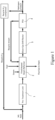
- FIG. 1 a block diagram of a conventional natural gas hydrogen production unit is shown, wherein export steam is not illustrated but is anyway present and it is described below and wherein the natural gas feedstock is fed under pressure to a pre-treatment unit 1 for the removal of those compounds that are detrimental for the steam reforming catalyst downstream.
- the pre-treatment unit 1 performs a first hydrogenation step and a second desulfurization step, optionally combined in one single step.
- the first step is conducted in a fixed bed catalytic reactor using CoMox or NiMox catalyst to hydrogenate organic sulfur into H 2 S and organic chlorine components into hydrogen chloride. Olefins present in the feed are hydrogenated as well in this step.
- the required hydrogen ( ⁇ 3 mol%, typical value with natural gas feedstock) is recycled from the H 2 product stream and/or taken from an available hydrogen source from battery limit.
- the produced hydrogenated compounds are then sent to the desulfurization step, in which they react typically with zinc oxide beds for H 2 S adsorption, optionally equipped with a material for hydrogen chloride adsorption.
- reaction 2 converts part of the CO produced by the first reaction into additional H 2 and CO 2 .
- H 2 O ⁇ CO 2 + H 2 ⁇ H 0 - 41 kJ/mol (2)
- the process steam added to the feed is in excess of the stoichiometric quantity so as to improve the hydrocarbons conversion and prevent any carbon deposition over the catalyst. Reforming temperatures are selected in a high range (typically 850 ⁇ 920 °C) in order to obtain high hydrogen yields.
- the operation of the steam reforming reaction inside a fired heater causes an excess heat generation related to the low thermal efficiency of the radiant section. The heat in excess is normally recovered in the convection section through high pressure steam generation.
- HTS high temperature shift conversion stage
- the HTS shift reactor 3 is a fixed bed adiabatic reactor using an iron/chromium/copper oxide catalyst which converts the carbon monoxide and steam present in the syngas into additional hydrogen and carbon dioxide according to the water gas shift reaction (reaction 2).
- reaction 2 water gas shift reaction
- an additional stage of shift conversion at lower temperature (LTS) is installed downstream and operated.
- the process syngas at the outlet of the shift conversion stage is cooled down to about 40 °C through a heat recovery section and a final cooler., Downstream, the equipment for water condensate removal is installed, from which the syngas is sent to a PSA unit 4 to perform the raw hydrogen purification.
- the PSA unit 4 operates through short adsorption/ desorption cycles conducted over selected adsorbent materials and operated in parallel vessels at different time stages.
- the hydrogen is released from the PSA unit 4 at the set pressure (typically about 20 barg for refinery applications, for example).
- the hydrogen recovery factor of PSA can achieve values up to 90%, while the hydrogen balance, together with the impurities present in the raw hydrogen stream, is released in a purge gas stream (off-gas or recycle stream) and leaves the PSA unit 4 at low pressure ( ⁇ 0.3 bar g).
- PSA unit 4 can reach hydrogen +purity up to 99,9999% vol. Typical hydrogen purity specification in refinery is >99.9%.
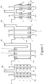
- the burners 7 may be positioned on the two sides of the lateral walls (side fired) (Fig. 2a); on the top of a radiant section 8a (top-fired) (Fig. 2b); although other configurations are available in the market such as bottom firing design (Fig. 2c) or the terrace- wall arrangement (Fig. 2d).
- Figure 3 shows a schematic representation of a top fired steam reforming furnace 6 according to the prior art, comprising a radiant section 8a with reforming tubes 9 which contain the catalyst (and consequently also called herein below catalytic tubes 9) and burners 7 on the roof, and a convection section 8b where the flue gases coming from the radiant section 8a are cooled down by preheating the process streams, generating steam and optionally preheating the combustion air flow.
- Flue gases are discharged into the atmosphere through an induced draft fan and a stack (not shown).
- the thermal efficiency of the furnace radiant section 8a determines the temperature of the flue gas stream at the exit from the radiant section 8a, which is the so called “bridge wall temperature" or T bw . Its value, together with the flue gas flowrate derived by the overall heat balance, determines the heat available for downstream convective heat recovery in the convection section 8b.
- Burners 7 are usually fed with fuel and off-gas recovered by downstream PSA 4.
- Each catalytic tube 9 is essentially a fixed bed reactor, where the feed is entering at the top and leaving at the bottom of the reformer radiant section 8a through curved connections, called pigtails (not shown), which allow enough movement to accommodate the thermal expansion of the tubes.
- the catalytic tubes 9 are made of special materials such as HP 25/35Ni-Cr alloy, able to withstand metal temperatures up to 1000°C. Due to the presence of the flame from burners 7, it is mandatory to well ensure the flame is properly developed along the overall length of the catalytic tubes 9.
- the length of the catalytic tubes 9 is in the range of 10-13 meters with an internal diameter from 7.6 to 12.7 cm. Thickness is normally calculated on the basis of creep strength data with a targeted lifetime of 100000h at the maximum metal temperature. This is mandatory due to the presence of flame in close proximity to the metal catalytic tube 9 in the radiant section 8a.
- the key information to calculate the number of catalytic tubes 9 in the radiant section 8a is the thermal duty calculated through the heat and material balance around the reformer. Once the average heat flux and the surface of each single catalytic tube 9 is fixed, the number of catalytic tubes 9 can be determined.
- fired heated steam reformers 2 are designed in order to guarantee the required thermal exchange surface, more than the required catalytic volume.
- Tube material limit and corresponding heat transfer is the limiting step in the design. Accordingly, usually the installed catalyst volume is overdesigned compared to the actual need for reaction to reach thermodynamic equilibrium at the outlet reforming temperature.
- WO2019228798 endothermic reactions heated by electrical resistance heating, and in particular a reactor system and a process for carrying out steam reforming of a feed gas comprising hydrocarbons where the heat for the endothermic reaction is provided by resistance heating are disclosed.
- said reactor system comprises:
- the solution according to the present invention with the aim of providing an apparatus for hydrogen production from a hydrocarbon feed, e.g. natural gas or biogas or another raw hydrocarbon feed, the apparatus comprising an electrically heated steam reformer wherein heat is provided through an easy to install or replace and simple to manage electrical device.
- a hydrocarbon feed e.g. natural gas or biogas or another raw hydrocarbon feed
- the apparatus comprising an electrically heated steam reformer wherein heat is provided through an easy to install or replace and simple to manage electrical device.
- the apparatus for hydrogen production according to the present invention involves the possibility to use shorter catalytic tubes, thus obtaining a more compact system.
- a further aim of the invention is that said an apparatus for hydrogen production can be implemented with substantially limited costs compared with reactors using structured catalysts according to the prior art.
- Not last aim of the invention is that of proposing an apparatus for hydrogen production being substantially simple, reliable and less risky in terms of explosion related to combustion of the systems according to the prior art.
- the apparatus for hydrogen production according to the present invention is based on the absence of burners in the furnace and adoption of a plurality of electrical devices in the form of electrical resistances that can be mounted on the outside of catalytic tubes, in order to sustain the thermal duty of the reaction with an efficient and easy to manage solution, both in terms of operation management and in terms of maintenance and even replacement due to damages.
- a heavy device may be provided floating at the top of the catalyst bed or a similar solution may be implemented.
- the system of catalytic sections represents the base unit 11 that can be replicated a certain number of times, depending on the overall addressed capacity of the plant.
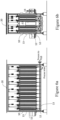
- the apparatus for hydrogen production according to the present invention is based on the use of electrical resistances, indicated in figure 4b with numeral 12, which can be embedded or installed on the surface of half cylinders 13 arranged around the catalytic sections 10.
- the external portion of the half cylinders 13 is made of insulating material.
- the electrical resistances 12 can be arranged directly inside the catalytic bed, i.e. in the core.
- the base unit 11 is realized with a plurality of catalytic sections 10 arranged in series, in such a way that the overall length of the catalytic sections 10 would lead to the same conversion of a conventional tube.
- four catalytic sections 10 are grouped together to result in an overall catalytic equivalent tube, each catalytic section 10 being characterized by the length of 3.5-4m.
- each catalytic section 10 has a plurality of heating devices, each device comprising an electrical resistance 12, distributed along the length of the tube, in order to determine an optimal temperature profile and therewith an optimal heat flux over the length of the tube, with the aim of optimizing the conversion.
- each electrical resistance 12 is positioned on the inside of a half cylinder 13 ( Fig. 4b ), the external portion of the half cylinder being made with an insulating material.
- the electrical resistance 12 wrapped around the catalytic section 10 is therefore in close contact with the catalytic section.
- each catalytic section comprises two half-cylinders arranged around the catalytic section for its entire length.
- the gas flow is directed from the top to the bottom in each catalytic subsection, thereby avoiding fluidization problems.
- catalytic subsections can be arranged horizontally, leading to a significantly lower structure, allowing for easier maintenance.
- bayonet tubes can be used to ensure the gas flow from top side, from bottom side or horizontally. This solution also enables the use of a whole cylinder as electrical device.
- the overall structure of the furnace can be simplified, as it eliminates the need for the burners, the convective section collecting flue gases, the stack for flue gas collection. Additionally, all auxiliaries related to air, flue gas and purge gas feeding, including those needed to capture the CO 2 from the flue gas, can be smaller or even be removed in some cases.
- An inspectional observation door 14 allows detection of hot spots and can bring to local mitigation of heat by modulating the electric power provided by the correspondent heating elements.
- electric elements are controlled by remote without presence of personnel on the steam reformer.
- the furnace can be provided with a system for hydrogen separation, directly inside the catalytic tube.
- the apparatus for hydrogen production according to the present invention was used to treat a natural gas feed with the composition shown in Table 1: Table 1 Total Molar Component Fractions % vol Pentane 0 Butane 0 i-butane 0 Propane 0.5 Ethane 2 Hexane 0 Methane 95.5 CO 0 CO 2 0 H 2 0 H 2 O 0 N 2 2 O 2 0 Ar 0 H 2 S 0 SO 2 0 i-pentane 0
- Figure 7a shows the temperature profile along the catalytic tube in an electrical reformer according to the present invention
- Figure 7b shows the temperature profile along the catalytic tube in a conventional gas fired heated reformer.
- Figures 7a and 7b make evident that the main difference between conventional fired heated reformer and electrical reformer is the difference of tube metal temperature reached by catalytic tube for each application.
- Figures 7a and 7b show that given the same average bulk temperature (inside the catalytic bed), with electrical heating it is possible to keep a lower portion of the tube at the highest temperature, therefore limiting the stress on it and in the overall to maintain the catalytic tube lifetime as high as possible.
- a reactor for hydrogen production according to the present invention is smaller than a fired heated reactor according to the prior art.
- the height of the construction is smaller and implies easier maintenance, lower civil construction costs and fewer risks of regulatory constraints.
- the different catalytic sections 10 can be arranged in easily transportable modules, which can then be easily installed on site, without the need for erecting a supporting structure.
- the apparatus for hydrogen production according to the present invention allows not only for the avoidance of any flame impingement, but also for a more uniform heat flux along the catalytic sections, resulting in a smaller catalyst volume.
- top fired steam reformer top fired steam reformer
- side fired steam reformer side fired steam reformer
- terrace steam reformer heating through the use of electric elements located around the heating area of catalytic sections allows for a more uniform distribution of heat around each single catalyst section and lower maximum temperature, with benefit for the catalytic sections lifetime.
- the apparatus for hydrogen production according to the present invention also allows to avoid other heating maldistribution affecting apparatuses for hydrogen production according to the prior art, such as change in purge gas composition, change in make-up fuel gas composition, uneven air distribution.
- the smaller catalyst volume together with the use of shorter catalytic sections 10 to replace the conventional catalytic tubes allows to realize a more compact system, with smaller overall footprint, with significant saving in foundations and more in general smaller size of the steam reforming reactor.
- Additional advantages comprise modular configuration and easier maintenance, less complex design for the reformer furnace, in particular because of no need of a convective section and no need of fans, in contrast with the conventional design of a reformer furnace.
- Division of catalytic tubes in catalytic sections, grouped in sectors, allows for an optimal design for the specific location of the sector. This feature can bring to an extension of lifetime of each sector and to a uniformity of the lifetime between sectors.
- a single sector fails, for example as a consequence of a deterioration of the catalyst, while the others, arranged in series, are in good conditions, replacement is limited to the failed sector, reducing impact.
- the modular heating system would allow continued operation, by changing the temperature profile along the tubes, thereby optimizing output. This possibility adds to the system according to the present invention an additional advantage with respect to the conventional fired reformer.
- Bottom inlet terminal allows to avoid to bring inlet piping system at high elevation from ground.
- Inlet Piping circuit is short with benefits for pressure drop and thermal losses.
- the apparatus load bearing structure is reduced.
- inlet location at the bottom allows to avoid long inlet pigtails at the top, reducing the relative risk to the management of thermal expansion of these ones combined with expansion of the tubes.
- In and outlet terminals are close to the fixed points of the system. No penthouse is required except for protection of catalytic section top flanges. The absence of fuel piping, combustion air ducts, purge gas piping, inlet piping system makes top area safer, needless of ordinary maintenance.
- the optimization of heat distribution along the catalytic sections 10 also allows for the possibility to reduce S/C ratio and CO 2 emissions compared with gas heated steam reformer, and more in general a reduced feed consumption, absence of fuel consumption and optionally, no export steam. Such optimization implies an about 40% higher efficiency (LHV basis).
- Noise due to combustion is not present, limited noise being due to the fluid dynamic, namely to the flow of process gases in piping.
- An additional advantage is reduced starting time of the apparatus. In fact, all sectors can start simultaneously avoiding uneven maldistribution during starting time (typical for gas burned steam reformers).
- the reforming reaction can be carried out at temperature lower than 650°C, with a consequent reduction in energy consumption and enabling the use of less expensive materials for the reforming tubes; (ii) a CH 4 conversion as high as 90% can be achieved also at temperature lower than 650°C; (iii) the downstream water gas shift reactor can be removed since such reaction can be performed in the reforming itself.
- the apparatus for hydrogen production according to the present invention also allows for flexibility arrangement for other endothermic reaction.
- the solution may be applied for instance also for reactions such as Propane dehydrogenation for propylene production and ammonia cracking for hydrogen production.
- the flexibility due to the use of electrical devices providing heat to the system allows for a simple reconfiguration of the electrical heat sources, in order to adapt to different implementations.
Landscapes
- Chemical & Material Sciences (AREA)
- Chemical Kinetics & Catalysis (AREA)
- Organic Chemistry (AREA)
- Engineering & Computer Science (AREA)
- Combustion & Propulsion (AREA)
- Inorganic Chemistry (AREA)
- Health & Medical Sciences (AREA)
- General Health & Medical Sciences (AREA)
- Analytical Chemistry (AREA)
- General Chemical & Material Sciences (AREA)
- Oil, Petroleum & Natural Gas (AREA)
- Hydrogen, Water And Hydrids (AREA)
Claims (8)
- Vorrichtung zur Herstellung von Wasserstoff aus einer Kohlenwasserstoffbeschickung, wobei die Vorrichtung mindestens einen Dampfreformer umfasst, der mit einem elektrisch beheizten Dampfreformerofen versehen ist, der eine Vielzahl von katalytischen Rohren umfasst, die in Gruppen von in Reihe angeordneten katalytischen Rohrabschnitten (10) unterteilt sind, wobei die Gruppen parallel angeordnet sind, dadurch gekennzeichnet, dass der elektrisch beheizte Dampfreformer-Ofen frei von Brennern und einer Vielzahl von wärmeerzeugenden elektrischen Vorrichtungen in Form von elektrischen Widerständen (12) ist an der Außenseite der katalytischen Rohrabschnitte angebracht, um die thermische Leistung der Reformierungsreaktion zu unterstützen.
- Vorrichtung zur Herstellung von Wasserstoff nach Anspruch 1, dadurch gekennzeichnet, dass die wärmeerzeugenden elektrischen Einrichtungen eine halbzylindrische Form (13) haben und elektrische Widerstände umfassen, die auf einem Trägerelement angeordnet sind.
- Vorrichtung zur Herstellung von Wasserstoff nach Anspruch 2, dadurch gekennzeichnet, dass das Trägerelement aus einem isolierenden Material besteht und auf dem äußeren Teil der wärmeerzeugenden elektrischen Vorrichtung angeordnet ist, wobei die elektrischen Widerstände auf dem inneren Teil der wärmeerzeugenden elektrischen Vorrichtung um die katalytischen Rohrabschnitte herum angeordnet sind.
- Vorrichtung zur Herstellung von Wasserstoff nach einem der vorhergehenden Ansprüche, dadurch gekennzeichnet, dass zumindest einige der wärmeerzeugenden elektrischen Einrichtungen so konfiguriert sind, dass sie unabhängig von den anderen betrieben werden können.
- Vorrichtung zur Herstellung von Wasserstoff nach einem der Ansprüche 1 bis 4, dadurch gekennzeichnet, dass sie ein System zur Wasserstoffabtrennung umfasst, das zwischen den in Reihe angeordneten katalytischen Rohrabschnitten angeordnet ist.
- Vorrichtung zur Wasserstofferzeugung gemäß einem der Ansprüche 1 bis 4, dadurch gekennzeichnet, dass die Katalyserohre mit einem System zur Wasserstoffabtrennung versehen sind, das unmittelbar innerhalb der Katalyserohre angeordnet ist.
- Vorrichtung zur Herstellung von Wasserstoff nach Anspruch 5 oder 6, dadurch gekennzeichnet, dass das System zur Wasserstofftrennung eine Membran umfasst.
- Vorrichtung zur Herstellung von Wasserstoff nach Anspruch 7, dadurch gekennzeichnet, dass die Membran eine Membran auf Pd-Basis ist.
Applications Claiming Priority (1)
| Application Number | Priority Date | Filing Date | Title |
|---|---|---|---|
| PCT/IT2021/000040 WO2023012837A1 (en) | 2021-08-04 | 2021-08-04 | Apparatus for hydrogen production |
Publications (3)
| Publication Number | Publication Date |
|---|---|
| EP4380892A1 EP4380892A1 (de) | 2024-06-12 |
| EP4380892B1 true EP4380892B1 (de) | 2025-06-11 |
| EP4380892C0 EP4380892C0 (de) | 2025-06-11 |
Family
ID=78078321
Family Applications (1)
| Application Number | Title | Priority Date | Filing Date |
|---|---|---|---|
| EP21786603.7A Active EP4380892B1 (de) | 2021-08-04 | 2021-08-04 | Vorrichtung zur wasserstofferzeugung |
Country Status (10)
| Country | Link |
|---|---|
| US (1) | US20240342675A1 (de) |
| EP (1) | EP4380892B1 (de) |
| JP (1) | JP2024529010A (de) |
| AR (1) | AR126688A1 (de) |
| AU (1) | AU2021459504A1 (de) |
| CA (1) | CA3228286A1 (de) |
| ES (1) | ES3039540T3 (de) |
| PL (1) | PL4380892T3 (de) |
| TW (1) | TWI903097B (de) |
| WO (1) | WO2023012837A1 (de) |
Families Citing this family (2)
| Publication number | Priority date | Publication date | Assignee | Title |
|---|---|---|---|---|
| WO2023203392A1 (en) * | 2022-04-21 | 2023-10-26 | Nova Chemicals (International) S.A. | Externally heated coil for hydrocarbon cracking |
| EP4620562A1 (de) * | 2024-03-20 | 2025-09-24 | L'air Liquide, Societe Anonyme Pour L'etude Et L'exploitation Des Procedes Georges Claude | Vorrichtung zur durchführung einer endothermen reaktion einer gaseinspeisung |
Family Cites Families (11)
| Publication number | Priority date | Publication date | Assignee | Title |
|---|---|---|---|---|
| JPH07183043A (ja) * | 1993-12-22 | 1995-07-21 | Toshiba Corp | 燃料電池発電設備 |
| US7195663B2 (en) * | 1996-10-30 | 2007-03-27 | Idatech, Llc | Hydrogen purification membranes, components and fuel processing systems containing the same |
| JP4033988B2 (ja) * | 1997-11-27 | 2008-01-16 | 東洋エンジニアリング株式会社 | メタノ−ルの製造方法 |
| US6569227B2 (en) * | 2001-09-27 | 2003-05-27 | Idatech, Llc | Hydrogen purification devices, components and fuel processing systems containing the same |
| JP2002293502A (ja) * | 2001-03-29 | 2002-10-09 | Nippon Soken Inc | 改質装置 |
| US20070051041A1 (en) * | 2005-09-06 | 2007-03-08 | Genkin Eugene S | Plant capacity expansion and dynamic production control |
| JP5463124B2 (ja) * | 2009-11-19 | 2014-04-09 | 三菱重工業株式会社 | 水素製造装置 |
| US8790618B2 (en) * | 2009-12-17 | 2014-07-29 | Dcns Sa | Systems and methods for initiating operation of pressure swing adsorption systems and hydrogen-producing fuel processing systems incorporating the same |
| JP5658897B2 (ja) * | 2010-03-25 | 2015-01-28 | Jx日鉱日石エネルギー株式会社 | 改質装置及び燃料電池システム |
| ES2952184T3 (es) * | 2017-12-08 | 2023-10-30 | Topsoe As | Planta y proceso para producir gas de síntesis |
| PT3801871T (pt) * | 2018-05-31 | 2026-05-12 | Topsoe As | Reaes endotrmicas aquecidas por aquecimento por resistncia |
-
2021
- 2021-08-04 WO PCT/IT2021/000040 patent/WO2023012837A1/en not_active Ceased
- 2021-08-04 ES ES21786603T patent/ES3039540T3/es active Active
- 2021-08-04 AU AU2021459504A patent/AU2021459504A1/en active Pending
- 2021-08-04 CA CA3228286A patent/CA3228286A1/en active Pending
- 2021-08-04 EP EP21786603.7A patent/EP4380892B1/de active Active
- 2021-08-04 PL PL21786603.7T patent/PL4380892T3/pl unknown
- 2021-08-04 US US18/294,743 patent/US20240342675A1/en active Pending
- 2021-08-04 JP JP2024506808A patent/JP2024529010A/ja active Pending
-
2022
- 2022-07-26 TW TW111127970A patent/TWI903097B/zh active
- 2022-08-03 AR ARP220102075A patent/AR126688A1/es active IP Right Grant
Also Published As
| Publication number | Publication date |
|---|---|
| AU2021459504A1 (en) | 2024-03-14 |
| CA3228286A1 (en) | 2023-02-09 |
| JP2024529010A (ja) | 2024-08-01 |
| PL4380892T3 (pl) | 2025-09-29 |
| WO2023012837A1 (en) | 2023-02-09 |
| EP4380892C0 (de) | 2025-06-11 |
| US20240342675A1 (en) | 2024-10-17 |
| TW202317467A (zh) | 2023-05-01 |
| EP4380892A1 (de) | 2024-06-12 |
| AR126688A1 (es) | 2023-11-01 |
| ES3039540T3 (en) | 2025-10-22 |
| TWI903097B (zh) | 2025-11-01 |
Similar Documents
| Publication | Publication Date | Title |
|---|---|---|
| From et al. | Electrified steam methane reforming of biogas for sustainable syngas manufacturing and next-generation of plant design: A pilot plant study | |
| AU2020412238B2 (en) | Electrically heated reactor, a furnace comprising said reactor and a method for gas conversions using said reactor | |
| US6299994B1 (en) | Process for providing a pure hydrogen stream for use with fuel cells | |
| US6280864B1 (en) | Control system for providing hydrogen for use with fuel cells | |
| US6190623B1 (en) | Apparatus for providing a pure hydrogen stream for use with fuel cells | |
| AU2019294262A1 (en) | Electrically heated reactor and a process for gas conversions using said reactor | |
| US12017914B2 (en) | Steam or dry reforming of hydrocarbons | |
| KR20240017021A (ko) | Co2 시프트를 위한 열교환 반응기 | |
| US20230339747A1 (en) | Syngas stage for chemical synthesis plant | |
| US20240342675A1 (en) | Apparatus for hydrogen production | |
| EP3980172B1 (de) | Verfahren zur dampfreformierung mit geringen kohlendioxidemissionen | |
| US20080219901A1 (en) | Cylindrical Steam Reformer Having Integrated Heat Exchanger | |
| HK40074325A (en) | Process of steam reforming with low carbon dioxide emissions | |
| EA050952B1 (ru) | Теплообменный реактор для конверсии co2 | |
| EP4739621A1 (de) | Anlage und verfahren zur herstellung von wasserstoff aus kohlenwasserstoffen mit verringerten co2-emissionen |
Legal Events
| Date | Code | Title | Description |
|---|---|---|---|
| STAA | Information on the status of an ep patent application or granted ep patent |
Free format text: STATUS: UNKNOWN |
|
| STAA | Information on the status of an ep patent application or granted ep patent |
Free format text: STATUS: THE INTERNATIONAL PUBLICATION HAS BEEN MADE |
|
| PUAI | Public reference made under article 153(3) epc to a published international application that has entered the european phase |
Free format text: ORIGINAL CODE: 0009012 |
|
| STAA | Information on the status of an ep patent application or granted ep patent |
Free format text: STATUS: REQUEST FOR EXAMINATION WAS MADE |
|
| 17P | Request for examination filed |
Effective date: 20240222 |
|
| AK | Designated contracting states |
Kind code of ref document: A1 Designated state(s): AL AT BE BG CH CY CZ DE DK EE ES FI FR GB GR HR HU IE IS IT LI LT LU LV MC MK MT NL NO PL PT RO RS SE SI SK SM TR |
|
| DAV | Request for validation of the european patent (deleted) | ||
| DAX | Request for extension of the european patent (deleted) | ||
| GRAP | Despatch of communication of intention to grant a patent |
Free format text: ORIGINAL CODE: EPIDOSNIGR1 |
|
| STAA | Information on the status of an ep patent application or granted ep patent |
Free format text: STATUS: GRANT OF PATENT IS INTENDED |
|
| RIC1 | Information provided on ipc code assigned before grant |
Ipc: B01J 8/06 20060101ALI20250129BHEP Ipc: C01B 3/38 20060101AFI20250129BHEP |
|
| INTG | Intention to grant announced |
Effective date: 20250219 |
|
| GRAS | Grant fee paid |
Free format text: ORIGINAL CODE: EPIDOSNIGR3 |
|
| GRAA | (expected) grant |
Free format text: ORIGINAL CODE: 0009210 |
|
| STAA | Information on the status of an ep patent application or granted ep patent |
Free format text: STATUS: THE PATENT HAS BEEN GRANTED |
|
| AK | Designated contracting states |
Kind code of ref document: B1 Designated state(s): AL AT BE BG CH CY CZ DE DK EE ES FI FR GB GR HR HU IE IS IT LI LT LU LV MC MK MT NL NO PL PT RO RS SE SI SK SM TR |
|
| REG | Reference to a national code |
Ref country code: GB Ref legal event code: FG4D |
|
| REG | Reference to a national code |
Ref country code: CH Ref legal event code: EP |
|
| REG | Reference to a national code |
Ref country code: IE Ref legal event code: FG4D |
|
| REG | Reference to a national code |
Ref country code: DE Ref legal event code: R096 Ref document number: 602021032194 Country of ref document: DE |
|
| U01 | Request for unitary effect filed |
Effective date: 20250704 |
|
| U07 | Unitary effect registered |
Designated state(s): AT BE BG DE DK EE FI FR IT LT LU LV MT NL PT RO SE SI Effective date: 20250711 |
|
| U20 | Renewal fee for the european patent with unitary effect paid |
Year of fee payment: 5 Effective date: 20250711 |
|
| PGFP | Annual fee paid to national office [announced via postgrant information from national office to epo] |
Ref country code: ES Payment date: 20250909 Year of fee payment: 5 |
|
| PG25 | Lapsed in a contracting state [announced via postgrant information from national office to epo] |
Ref country code: GR Free format text: LAPSE BECAUSE OF FAILURE TO SUBMIT A TRANSLATION OF THE DESCRIPTION OR TO PAY THE FEE WITHIN THE PRESCRIBED TIME-LIMIT Effective date: 20250912 Ref country code: NO Free format text: LAPSE BECAUSE OF FAILURE TO SUBMIT A TRANSLATION OF THE DESCRIPTION OR TO PAY THE FEE WITHIN THE PRESCRIBED TIME-LIMIT Effective date: 20250911 |
|
| PGFP | Annual fee paid to national office [announced via postgrant information from national office to epo] |
Ref country code: PL Payment date: 20250814 Year of fee payment: 5 Ref country code: TR Payment date: 20250826 Year of fee payment: 5 |
|
| PGFP | Annual fee paid to national office [announced via postgrant information from national office to epo] |
Ref country code: GB Payment date: 20250814 Year of fee payment: 5 |
|
| PG25 | Lapsed in a contracting state [announced via postgrant information from national office to epo] |
Ref country code: HR Free format text: LAPSE BECAUSE OF FAILURE TO SUBMIT A TRANSLATION OF THE DESCRIPTION OR TO PAY THE FEE WITHIN THE PRESCRIBED TIME-LIMIT Effective date: 20250611 |
|
| PG25 | Lapsed in a contracting state [announced via postgrant information from national office to epo] |
Ref country code: RS Free format text: LAPSE BECAUSE OF FAILURE TO SUBMIT A TRANSLATION OF THE DESCRIPTION OR TO PAY THE FEE WITHIN THE PRESCRIBED TIME-LIMIT Effective date: 20250911 |
|
| RAP4 | Party data changed (patent owner data changed or rights of a patent transferred) |
Owner name: KT TECH S.P.A. |
|
| U1H | Name or address of the proprietor changed after the registration of the unitary effect |
Owner name: KT TECH S.P.A.; IT |
|
| PG25 | Lapsed in a contracting state [announced via postgrant information from national office to epo] |
Ref country code: IS Free format text: LAPSE BECAUSE OF FAILURE TO SUBMIT A TRANSLATION OF THE DESCRIPTION OR TO PAY THE FEE WITHIN THE PRESCRIBED TIME-LIMIT Effective date: 20251011 |
|
| PG25 | Lapsed in a contracting state [announced via postgrant information from national office to epo] |
Ref country code: SM Free format text: LAPSE BECAUSE OF FAILURE TO SUBMIT A TRANSLATION OF THE DESCRIPTION OR TO PAY THE FEE WITHIN THE PRESCRIBED TIME-LIMIT Effective date: 20250611 |
|
| PG25 | Lapsed in a contracting state [announced via postgrant information from national office to epo] |
Ref country code: CZ Free format text: LAPSE BECAUSE OF FAILURE TO SUBMIT A TRANSLATION OF THE DESCRIPTION OR TO PAY THE FEE WITHIN THE PRESCRIBED TIME-LIMIT Effective date: 20250611 |
|
| PG25 | Lapsed in a contracting state [announced via postgrant information from national office to epo] |
Ref country code: SK Free format text: LAPSE BECAUSE OF FAILURE TO SUBMIT A TRANSLATION OF THE DESCRIPTION OR TO PAY THE FEE WITHIN THE PRESCRIBED TIME-LIMIT Effective date: 20250611 |
|
| REG | Reference to a national code |
Ref country code: CH Ref legal event code: H13 Free format text: ST27 STATUS EVENT CODE: U-0-0-H10-H13 (AS PROVIDED BY THE NATIONAL OFFICE) Effective date: 20260324 |
|
| PG25 | Lapsed in a contracting state [announced via postgrant information from national office to epo] |
Ref country code: MC Free format text: LAPSE BECAUSE OF FAILURE TO SUBMIT A TRANSLATION OF THE DESCRIPTION OR TO PAY THE FEE WITHIN THE PRESCRIBED TIME-LIMIT Effective date: 20250611 |
|
| PLBE | No opposition filed within time limit |
Free format text: ORIGINAL CODE: 0009261 |
|
| STAA | Information on the status of an ep patent application or granted ep patent |
Free format text: STATUS: NO OPPOSITION FILED WITHIN TIME LIMIT |
|
| PG25 | Lapsed in a contracting state [announced via postgrant information from national office to epo] |
Ref country code: CH Free format text: LAPSE BECAUSE OF NON-PAYMENT OF DUE FEES Effective date: 20250831 |
|
| REG | Reference to a national code |
Ref country code: CH Ref legal event code: L10 Free format text: ST27 STATUS EVENT CODE: U-0-0-L10-L00 (AS PROVIDED BY THE NATIONAL OFFICE) Effective date: 20260423 |
|
| 26N | No opposition filed |
Effective date: 20260312 |
|
| PG25 | Lapsed in a contracting state [announced via postgrant information from national office to epo] |
Ref country code: IE Free format text: LAPSE BECAUSE OF NON-PAYMENT OF DUE FEES Effective date: 20250804 |
|
| U20 | Renewal fee for the european patent with unitary effect paid |
Year of fee payment: 6 Effective date: 20260707 |