EP4381160B1 - Hoch wärmedämmende profildichtung - Google Patents
Hoch wärmedämmende profildichtung Download PDFInfo
- Publication number
- EP4381160B1 EP4381160B1 EP23710734.7A EP23710734A EP4381160B1 EP 4381160 B1 EP4381160 B1 EP 4381160B1 EP 23710734 A EP23710734 A EP 23710734A EP 4381160 B1 EP4381160 B1 EP 4381160B1
- Authority
- EP
- European Patent Office
- Prior art keywords
- phr
- profile seal
- profile
- elastomer composition
- profile sealing
- Prior art date
- Legal status (The legal status is an assumption and is not a legal conclusion. Google has not performed a legal analysis and makes no representation as to the accuracy of the status listed.)
- Active
Links
Images


Classifications
-
- E—FIXED CONSTRUCTIONS
- E06—DOORS, WINDOWS, SHUTTERS, OR ROLLER BLINDS IN GENERAL; LADDERS
- E06B—FIXED OR MOVABLE CLOSURES FOR OPENINGS IN BUILDINGS, VEHICLES, FENCES OR LIKE ENCLOSURES IN GENERAL, e.g. DOORS, WINDOWS, BLINDS, GATES
- E06B3/00—Window sashes, door leaves, or like elements for closing wall or like openings; Layout of fixed or moving closures, e.g. windows in wall or like openings; Features of rigidly-mounted outer frames relating to the mounting of wing frames
- E06B3/54—Fixing of glass panes or like plates
- E06B3/58—Fixing of glass panes or like plates by means of borders, cleats, or the like
- E06B3/62—Fixing of glass panes or like plates by means of borders, cleats, or the like of rubber-like elastic cleats
-
- C—CHEMISTRY; METALLURGY
- C09—DYES; PAINTS; POLISHES; NATURAL RESINS; ADHESIVES; COMPOSITIONS NOT OTHERWISE PROVIDED FOR; APPLICATIONS OF MATERIALS NOT OTHERWISE PROVIDED FOR
- C09J—ADHESIVES; NON-MECHANICAL ASPECTS OF ADHESIVE PROCESSES IN GENERAL; ADHESIVE PROCESSES NOT PROVIDED FOR ELSEWHERE; USE OF MATERIALS AS ADHESIVES
- C09J109/00—Adhesives based on homopolymers or copolymers of conjugated diene hydrocarbons
-
- C—CHEMISTRY; METALLURGY
- C08—ORGANIC MACROMOLECULAR COMPOUNDS; THEIR PREPARATION OR CHEMICAL WORKING-UP; COMPOSITIONS BASED THEREON
- C08J—WORKING-UP; GENERAL PROCESSES OF COMPOUNDING; AFTER-TREATMENT NOT COVERED BY SUBCLASSES C08B, C08C, C08F, C08G or C08H
- C08J9/00—Working-up of macromolecular substances to porous or cellular articles or materials; After-treatment thereof
- C08J9/04—Working-up of macromolecular substances to porous or cellular articles or materials; After-treatment thereof using blowing gases generated by a previously added blowing agent
- C08J9/06—Working-up of macromolecular substances to porous or cellular articles or materials; After-treatment thereof using blowing gases generated by a previously added blowing agent by a chemical blowing agent
- C08J9/10—Working-up of macromolecular substances to porous or cellular articles or materials; After-treatment thereof using blowing gases generated by a previously added blowing agent by a chemical blowing agent developing nitrogen, the blowing agent being a compound containing a nitrogen-to-nitrogen bond
- C08J9/104—Hydrazines; Hydrazides; Semicarbazides; Semicarbazones; Hydrazones; Derivatives thereof
- C08J9/105—Hydrazines; Hydrazides; Semicarbazides; Semicarbazones; Hydrazones; Derivatives thereof containing sulfur
-
- C—CHEMISTRY; METALLURGY
- C08—ORGANIC MACROMOLECULAR COMPOUNDS; THEIR PREPARATION OR CHEMICAL WORKING-UP; COMPOSITIONS BASED THEREON
- C08J—WORKING-UP; GENERAL PROCESSES OF COMPOUNDING; AFTER-TREATMENT NOT COVERED BY SUBCLASSES C08B, C08C, C08F, C08G or C08H
- C08J9/00—Working-up of macromolecular substances to porous or cellular articles or materials; After-treatment thereof
- C08J9/32—Working-up of macromolecular substances to porous or cellular articles or materials; After-treatment thereof from compositions containing microballoons, e.g. syntactic foams
-
- C—CHEMISTRY; METALLURGY
- C08—ORGANIC MACROMOLECULAR COMPOUNDS; THEIR PREPARATION OR CHEMICAL WORKING-UP; COMPOSITIONS BASED THEREON
- C08L—COMPOSITIONS OF MACROMOLECULAR COMPOUNDS
- C08L23/00—Compositions of homopolymers or copolymers of unsaturated aliphatic hydrocarbons having only one carbon-to-carbon double bond; Compositions of derivatives of such polymers
- C08L23/02—Compositions of homopolymers or copolymers of unsaturated aliphatic hydrocarbons having only one carbon-to-carbon double bond; Compositions of derivatives of such polymers not modified by chemical after-treatment
- C08L23/16—Ethylene-propylene or ethylene-propylene-diene copolymers
-
- E—FIXED CONSTRUCTIONS
- E06—DOORS, WINDOWS, SHUTTERS, OR ROLLER BLINDS IN GENERAL; LADDERS
- E06B—FIXED OR MOVABLE CLOSURES FOR OPENINGS IN BUILDINGS, VEHICLES, FENCES OR LIKE ENCLOSURES IN GENERAL, e.g. DOORS, WINDOWS, BLINDS, GATES
- E06B7/00—Special arrangements or measures in connection with doors or windows
- E06B7/16—Sealing arrangements on wings or parts co-operating with the wings
- E06B7/22—Sealing arrangements on wings or parts co-operating with the wings by means of elastic edgings, e.g. elastic rubber tubes; by means of resilient edgings, e.g. felt or plush strips, resilient metal strips
- E06B7/23—Plastic, sponge rubber, or like strips or tubes
- E06B7/2305—Plastic, sponge rubber, or like strips or tubes with an integrally formed part for fixing the edging
- E06B7/2307—Plastic, sponge rubber, or like strips or tubes with an integrally formed part for fixing the edging with a single sealing-line or -plane between the wing and the part co-operating with the wing
- E06B7/2309—Plastic, sponge rubber, or like strips or tubes with an integrally formed part for fixing the edging with a single sealing-line or -plane between the wing and the part co-operating with the wing with a hollow sealing part
-
- E—FIXED CONSTRUCTIONS
- E06—DOORS, WINDOWS, SHUTTERS, OR ROLLER BLINDS IN GENERAL; LADDERS
- E06B—FIXED OR MOVABLE CLOSURES FOR OPENINGS IN BUILDINGS, VEHICLES, FENCES OR LIKE ENCLOSURES IN GENERAL, e.g. DOORS, WINDOWS, BLINDS, GATES
- E06B7/00—Special arrangements or measures in connection with doors or windows
- E06B7/16—Sealing arrangements on wings or parts co-operating with the wings
- E06B7/22—Sealing arrangements on wings or parts co-operating with the wings by means of elastic edgings, e.g. elastic rubber tubes; by means of resilient edgings, e.g. felt or plush strips, resilient metal strips
- E06B7/23—Plastic, sponge rubber, or like strips or tubes
- E06B7/2305—Plastic, sponge rubber, or like strips or tubes with an integrally formed part for fixing the edging
- E06B7/2307—Plastic, sponge rubber, or like strips or tubes with an integrally formed part for fixing the edging with a single sealing-line or -plane between the wing and the part co-operating with the wing
- E06B7/231—Plastic, sponge rubber, or like strips or tubes with an integrally formed part for fixing the edging with a single sealing-line or -plane between the wing and the part co-operating with the wing with a solid sealing part
-
- E—FIXED CONSTRUCTIONS
- E06—DOORS, WINDOWS, SHUTTERS, OR ROLLER BLINDS IN GENERAL; LADDERS
- E06B—FIXED OR MOVABLE CLOSURES FOR OPENINGS IN BUILDINGS, VEHICLES, FENCES OR LIKE ENCLOSURES IN GENERAL, e.g. DOORS, WINDOWS, BLINDS, GATES
- E06B7/00—Special arrangements or measures in connection with doors or windows
- E06B7/16—Sealing arrangements on wings or parts co-operating with the wings
- E06B7/22—Sealing arrangements on wings or parts co-operating with the wings by means of elastic edgings, e.g. elastic rubber tubes; by means of resilient edgings, e.g. felt or plush strips, resilient metal strips
- E06B7/23—Plastic, sponge rubber, or like strips or tubes
- E06B7/2305—Plastic, sponge rubber, or like strips or tubes with an integrally formed part for fixing the edging
- E06B7/2312—Plastic, sponge rubber, or like strips or tubes with an integrally formed part for fixing the edging with two or more sealing-lines or -planes between the wing and part co-operating with the wing
-
- E—FIXED CONSTRUCTIONS
- E06—DOORS, WINDOWS, SHUTTERS, OR ROLLER BLINDS IN GENERAL; LADDERS
- E06B—FIXED OR MOVABLE CLOSURES FOR OPENINGS IN BUILDINGS, VEHICLES, FENCES OR LIKE ENCLOSURES IN GENERAL, e.g. DOORS, WINDOWS, BLINDS, GATES
- E06B7/00—Special arrangements or measures in connection with doors or windows
- E06B7/16—Sealing arrangements on wings or parts co-operating with the wings
- E06B7/22—Sealing arrangements on wings or parts co-operating with the wings by means of elastic edgings, e.g. elastic rubber tubes; by means of resilient edgings, e.g. felt or plush strips, resilient metal strips
- E06B7/23—Plastic, sponge rubber, or like strips or tubes
- E06B7/2314—Plastic, sponge rubber, or like strips or tubes characterised by the material
-
- C—CHEMISTRY; METALLURGY
- C08—ORGANIC MACROMOLECULAR COMPOUNDS; THEIR PREPARATION OR CHEMICAL WORKING-UP; COMPOSITIONS BASED THEREON
- C08J—WORKING-UP; GENERAL PROCESSES OF COMPOUNDING; AFTER-TREATMENT NOT COVERED BY SUBCLASSES C08B, C08C, C08F, C08G or C08H
- C08J2203/00—Foams characterized by the expanding agent
- C08J2203/04—N2 releasing, ex azodicarbonamide or nitroso compound
-
- C—CHEMISTRY; METALLURGY
- C08—ORGANIC MACROMOLECULAR COMPOUNDS; THEIR PREPARATION OR CHEMICAL WORKING-UP; COMPOSITIONS BASED THEREON
- C08J—WORKING-UP; GENERAL PROCESSES OF COMPOUNDING; AFTER-TREATMENT NOT COVERED BY SUBCLASSES C08B, C08C, C08F, C08G or C08H
- C08J2203/00—Foams characterized by the expanding agent
- C08J2203/22—Expandable microspheres, e.g. Expancel®
-
- C—CHEMISTRY; METALLURGY
- C08—ORGANIC MACROMOLECULAR COMPOUNDS; THEIR PREPARATION OR CHEMICAL WORKING-UP; COMPOSITIONS BASED THEREON
- C08J—WORKING-UP; GENERAL PROCESSES OF COMPOUNDING; AFTER-TREATMENT NOT COVERED BY SUBCLASSES C08B, C08C, C08F, C08G or C08H
- C08J2300/00—Characterised by the use of unspecified polymers
- C08J2300/26—Elastomers
-
- C—CHEMISTRY; METALLURGY
- C08—ORGANIC MACROMOLECULAR COMPOUNDS; THEIR PREPARATION OR CHEMICAL WORKING-UP; COMPOSITIONS BASED THEREON
- C08J—WORKING-UP; GENERAL PROCESSES OF COMPOUNDING; AFTER-TREATMENT NOT COVERED BY SUBCLASSES C08B, C08C, C08F, C08G or C08H
- C08J2323/00—Characterised by the use of homopolymers or copolymers of unsaturated aliphatic hydrocarbons having only one carbon-to-carbon double bond; Derivatives of such polymers
- C08J2323/02—Characterised by the use of homopolymers or copolymers of unsaturated aliphatic hydrocarbons having only one carbon-to-carbon double bond; Derivatives of such polymers not modified by chemical after treatment
- C08J2323/16—Ethene-propene or ethene-propene-diene copolymers
Definitions
- the present invention relates to a highly heat-insulating profile seal made of an elastomer composition, a process for its production and the use of the profile seal for thermal insulation.
- TPE thermoplastic elastomers
- EPDM ethylene propylene diene rubber
- CR chloroprene rubber
- PVC polyvinyl chloride
- the thermal transmittance ( Uw value) is crucial for the quality of thermal insulation.
- the thermal transmittance Uw is the amount of heat that passes through 1 m2 of a building component (e.g. wall, concrete, roof) per unit of time (usually 1 second) at a temperature difference of 1 Kelvin (K).
- K Kelvin
- the Uw value is therefore a unit of measurement for heat loss.
- the window or door When calculating the Uw value for a window or door, it must be taken into account that the window or door consists of several components, in particular glazing and a frame.
- the Uw value of the window or door is determined from the respective Uw values of the individual components, taking into account the respective surface areas they occupy.
- the Uw value for standard glazing must not exceed 1.3 watts per square meter and Kelvin (W/(m 2 ⁇ K)).
- Windows with a Uw value of 0.9 W/(m 2 ⁇ K) are considered to have efficient thermal insulation.
- Windows with a Uw value of 0.8 W/(m 2 ⁇ K) or less are considered suitable for passive houses.
- the profile seal should be made of a material with a low thermal conductivity ⁇ .
- the thermal conductivity ⁇ corresponds to the heat flow that passes through an object with a surface area of 1 m 2 and a thickness of 1 m at a temperature difference of 1 K per second.
- a thermal conductivity of ⁇ 0.05 watts per meter and Kelvin (W/(m K)) is assumed for U w value calculations for profile seals.
- this thermal conductivity of 0.05 W/(m K) has so far only been achieved by materials with a density of 0.06-0.08 g/cm 3.
- the thermal conductivity of PVC is 0.14–0.17 W/(m ⁇ K) at a density of approximately 1.20–1.40 g/cm 3
- that of silicones is approximately 0.2–0.3 W/(m ⁇ K) at a density of approximately 0.76–1.07 g/cm 3
- 0.05 W/(m ⁇ K) at a density of 0.2 g/cm 3 .
- JP H08 12797 A a profile seal made of an elastomer composition comprising: 100 phr elastomer (A) and 0.1-20 phr expanded microspheres (B), wherein the average diameter of the expanded microspheres is 10-200 ⁇ m and the elastomer composition (1) has a density of 0.10-0.30 g/cm3.
- Sealing strips for motor vehicles comprising a main body element made of a high-density material and a sponge body made of a compressible material, wherein the sponge body contains rubber and expandable microspheres as a physical blowing agent.
- the high proportion of 25-40 phr expanded microspheres with an average diameter of 10-200 ⁇ m ensures a low density and low thermal conductivity of the elastomer composition and, surprisingly, simultaneously high stiffness of the material as well as high elasticity and good resilience. This was previously unattainable, especially not with chemical blowing agents.
- the object is further achieved by a method for producing a profile seal according to claim 14.
- a method for producing a profile seal comprises the steps of mixing a material mixture comprising 100 phr elastomer and 25-40 phr expandable Microspheres are heated to a temperature of 75-300 °C, and a profile seal is formed. Upon heating, the expandable microspheres expand to form expanded microspheres.
- the "material mixture” refers to the starting material that is heated and contains expandable microspheres
- the “elastomer composition” refers to the material obtained after heating, which contains expanded microspheres.
- the profile seal for windows and doors can in particular be a profile seal for building windows, building doors and building gates, i.e. it can be designed as a building (window/door/gate) profile seal.
- the profile seal comprises an elastomer to achieve high elasticity, as well as expanded microspheres, which enable high rigidity and low density, as well as low thermal conductivity.
- a seal can be an element or structure designed to prevent or limit unwanted transfer of material or heat from one place to another.
- the profile seal can be a seal in the form of a profile body that extends in a longitudinal direction or profile direction and whose cross-section has a certain geometric shape.
- the geometric shape of the cross-section does not change across the longitudinal direction or profile direction, so that the cross-sectional areas of the profile body are congruent at every position in the longitudinal direction.
- the profile seal can be designed as a central seal, side seal and/or as an insulating strip.
- the profile seal can be produced by extrusion, calendering, or pressing.
- Extrusion is a process in which a plastically deformable, viscous material is continuously pressed out of a shaping opening under pressure.
- the shaping opening can be a die, a nozzle, or a mouthpiece.
- the shaped mass can harden through cooling after exiting the shaping opening.
- Calendering is a process in which a material is passed through a system of several rollers arranged one above the other.
- Pressing is a process in which a material is placed between two solid bodies, preferably plates, and the two solid bodies are moved towards each other, exerting a force on the material between the two solid bodies.
- the elastomer composition from which the profile seal is formed has a density of 0.10-0.30 g/cm 3 , preferably of 0.12-0.28 g/cm 3 , and most preferably of 0.17-0.26 g/cm 3 . With these densities, particularly low thermal conductivities of the material can be achieved.
- the elastomer composition according to the invention comprises 25-40 phr, preferably 25-38 phr, of expanded microspheres. Surprisingly, these proportions of expanded microspheres allow for a particularly low thermal conductivity of the elastomer composition while simultaneously maintaining high stiffness, high elasticity, and good resilience.
- the profile seal according to the invention is produced from an elastomer composition by heating the material mixture to a temperature of 75-300 °C, preferably 200-280 °C, more preferably 210-270 °C, and forming a profile seal, for example by extrusion, calendering, or pressing. During heating, the expandable microspheres expand into expanded microspheres. If a crosslinker is included in the material mixture, crosslinking of the elastomer can also occur.
- the elastomer composition preferably contains 1-30 phr, more preferably 3-12 phr, most preferably 5-10 phr, of crosslinker.
- phr parts per hundred rubber
- the phr value can also be converted into weight percent in a manner known to those skilled in the art. To do this, the masses of the individual components are divided by the total mass of the composition. For example, a composition with 100 phr of elastomer, 10 phr of plasticizer, and 10 phr of expandable microspheres would correspond to a composition with 83.3 wt% elastomer, 8.3 wt% plasticizer, and 8.3 wt% expandable microspheres.
- the elastomer can be an elastomer or an elastomer blend (elastomer mixture).
- the elastomer in this material mixture or elastomer composition is preferably EPM (ethylene-propylene copolymer), EPDM (ethylene-propylene-diene rubber), or blends (mixtures) of EPDM and BR (butadiene rubber, i.e., polybutadiene).
- EPM ethylene-propylene copolymer
- EPDM ethylene-propylene-diene rubber
- blends (mixtures) of EPDM and BR butadiene rubber, i.e., polybutadiene).
- the elastomer provides the profile seal with high elasticity and high weather resistance.
- the material mixture for producing the profile seal comprises, in addition to the elastomer, also a crosslinker, for example, 1-30 phr crosslinker.
- the crosslinker reacts with the elastomer during heating/vulcanization, thus forming a more highly crosslinked elastomer. incorporated into the elastomer and is thus part of the elastomer composition that forms the profile seal. Therefore, the crosslinker is not listed as a separate component in the elastomer composition according to the invention.
- the plasticizer may comprise an oil, particularly a mineral oil, a vegetable oil, and/or a polymer.
- the polymer may comprise polyisobutylene.
- the plasticizer allows for optimization of the viscosity of the elastomer composition and adjustment of the hardness of the profile seal. Several different plasticizers can be used in an elastomer composition.
- the filler can be a substance that can be added to the elastomer composition to optimize its properties.
- fillers that can be used include carbon black, kaolin, chalk, or silica.
- Polymeric fillers can also be used.
- Polymeric fillers can include polypropylene and/or polyethylene.
- Flame-retardant fillers can include aluminum hydroxide, magnesium hydroxide, and/or antimony trioxide.
- Lightweight fillers comprising porous materials such as perlite can also be used.
- Aeropor 180 (hollow spheres based on aluminum silicate), Sil-cel (expanded perlite), and/or Cenospheres (hollow spheres based on aluminum silicate) and/or lightweight spheres ("light bubbles," e.g., borosilicate glass spheres) can be used.
- Fillers are used in a material mixture or elastomer composition. Fillers have the advantage of increasing the extrudability of the material mixture or elastomer composition. Furthermore, fillers can improve the mechanical properties of the profile seal. In particular, fillers can increase the stiffness of the profile seal and maintain or reduce its thermal conductivity.
- the crosslinker can be a substance or a mixture of substances that causes complete or partial crosslinking of the polymer chains of the elastomer or elastomer blend.
- the crosslinker can, in particular, be a crosslinker system comprising sulfur and/or peroxide, accelerators and/or activators, and/or a resin system.
- a peroxide can preferably be an organic peroxide compound or a mixture of organic peroxide compounds. Peroxides have the advantage of increasing the degree of crosslinking of the polymer chains and the rigidity of the profile seal.
- the activator can be a substance that activates the polymer chains to be crosslinked and/or the crosslinker.
- the activator can be stearic acid or zinc oxide.
- the activator has the advantage of enabling efficient crosslinking of polymer chains.
- the accelerator can be one or a mixture of several substances that increase the crosslinking rate (speed of crosslinking).
- the accelerator can be 2-mercaptobenzothiazole (MBT) and/or tetramethylthiuram disulfide (TMTD).
- MBT 2-mercaptobenzothiazole
- TMTD tetramethylthiuram disulfide
- the accelerator has the advantage of increasing the degree of crosslinking of the polymer chains and increasing the stiffness of the profile seal.
- Several different crosslinkers, crosslinking systems, activators, and/or accelerators can be used in a material mixture.
- Crosslinkers, crosslinking systems, activators, and/or accelerators have the advantage of increasing the stiffness of the profile seal.
- an optimal degree of crosslinking of the polymer chains, high stiffness and high elasticity of the profile seal, and optimal blowing behavior of the chemical and physical blowing agents can be achieved.
- expandable microspheres are understood to mean microscopic spheres, i.e. essentially spherical bodies with an average diameter in the micrometer range, in particular with an average diameter of 1-100 ⁇ m, preferably 5-50 ⁇ m, particularly preferably 6-40 ⁇ m, which have a shell made of thermoplastic material and have a volatile organic compound within the shell which can act as a blowing agent.
- the volatile organic compound is preferably an organic compound, preferably a hydrocarbon, with a boiling point of ⁇ 120°C, more preferably ⁇ 100°C, even more preferably ⁇ 60°C, and most preferably ⁇ 40°C.
- the boiling point is preferably below the so-called blowing temperature.
- the blowing temperature is a temperature high enough to soften the thermoplastic shell and increase the vapor pressure of the blowing agent, causing the microspheres to expand. The expansion results in a volume increase of at least twofold, preferably twenty to eighty-fold.
- expandable microspheres After expansion, the expandable microspheres are referred to as expanded microspheres.
- the material mixture therefore contains expandable microspheres, and the elastomer composition produced therefrom contains expanded microspheres.
- Expanded microspheres are therefore preferably understood to mean microspheres with a shell, preferably a closed shell, made of thermoplastic material, with an organic compound located inside the shell.
- the organic compound preferably has a boiling point of ⁇ 120°C, more preferably ⁇ 100°C, even more preferably ⁇ 60°C, and most preferably ⁇ 40°C.
- the organic compound is preferably a hydrocarbon, for example, isopentane.
- the thermoplastic material in particular a thermoplastic, is preferably a polymer based on polyacrylonitrile, polystyrene and/or PVC.
- the expandable microspheres preferably have a blowing temperature of 25°C to 300°C, preferably 100°C to 290°C, most preferably 200°C to 280°C. Expandable microspheres with a blowing temperature of 25 to Temperatures of 300 °C allow the microspheres to expand when the material mixture is heated.
- the volatile hydrocarbon compounds act as blowing agents and ensure particularly effective expansion of the hollow microspheres.
- the thermoplastic shell can soften under the influence of heat.
- the average diameter of the expandable microspheres is 1-100 ⁇ m, preferably 5-50 ⁇ m, particularly preferably 6-40 ⁇ m.
- an expanded microsphere or hollow microsphere is formed.
- the expanded microspheres or hollow microspheres have an average diameter of 10-200 ⁇ m, preferably 30-170 ⁇ m, more preferably 40-150 ⁇ m, most preferably 50-130 ⁇ m.
- the mean diameter of the expanded microspheres is determined by measuring the diameter of at least 20 expanded microspheres in a section through the elastomer composition under a microscope (e.g. a light microscope) and determining the arithmetic mean. In the case of microspheres that are not completely spherical, a diameter is randomly selected. When measuring the diameters of the expanded microspheres in a section through the elastomer composition, the actual diameters are not determined, but rather the diameters in a (random) section, and these diameters are smaller than the actual diameters because a random section generally does not pass through the center of the spheres. However, the mean diameters determined in a section using the measurement method described above result in the specified ranges of the mean diameters of the expanded microspheres.
- the average diameter of the expandable microspheres ie the microspheres before the expansion step, is in commercially available products in the It can be determined by measuring the diameter of at least 20 expandable microspheres, for example under a microscope, and determining the arithmetic mean.
- the average thickness of the shell of the expandable microspheres is preferably 1-3 ⁇ m, more preferably 1.5-2.5 ⁇ m.
- the average thickness of the shell of the expanded microspheres is preferably 0.02-0.5 ⁇ m, more preferably 0.05-0.3 ⁇ m, most preferably 0.08-0.2 ⁇ m.
- the expanded microspheres or hollow microspheres have the advantage that in the elastomer composition according to the invention which forms the profile seal, a low density of the elastomer composition or of the material of the profile seal can be achieved and at the same time a high rigidity of the material is still present.
- Expancel® microspheres such as Expancel 930 DU 120, can be used as expandable microspheres.
- the expandable microspheres can have a polymer shell comprising PAN (polyacrylonitrile).
- the polymer shell can consist of polystyrene and PAN (as a copolymer).
- the expansion temperature depends on the softening temperature of the polymer shell. Isopentane (boiling point 28 °C) can be used as the organic solvent for Expancel® microspheres.
- Expancel® microspheres In the expanded state, Expancel® microspheres typically have a diameter of approximately 120 ⁇ m.
- the expandable microspheres serve as a physical blowing agent, which is used to create pores and reduce density.
- the size of the resulting pores corresponds approximately to the size of the expanded microspheres, which is why the pore diameter is ⁇ 200 ⁇ m, preferably ⁇ 150 ⁇ m and more preferably ⁇ 130 ⁇ m, in particular the average diameter of the pores is 10-200 ⁇ m, preferably 30-170 ⁇ m, more preferably 40-150 ⁇ m, most preferably 50-130 ⁇ m.
- the additional advantage of expanded microspheres or physical blowing agents is that smaller pore diameters and thus a finer pore structure can be achieved than with chemical blowing agents. Furthermore, the pore size can be easily and precisely adjusted through the use of expandable microspheres.
- the surprising advantage of expandable microspheres is that, at the same density, a higher stiffness of the profile seal could be achieved than with chemical blowing agents, and a thermal conductivity of the elastomer composition of the profile seal of ⁇ ⁇ 0.060 W/(m K) could be achieved.
- a chemical blowing agent can be used.
- a chemical blowing agent can be a substance that decomposes at a certain temperature, releasing a gas, for example carbon dioxide.
- Examples of chemical blowing agents that can be used are isocyanate, water, azodicarbonamide, hydrazine, in particular p-toluenesulfonylhydrazide (TSH), and/or 4,4'-oxydi(benzenesulfonohydrazide) (OBSH) and/or sodium bicarbonate.
- TSH p-toluenesulfonylhydrazide
- OBSH 4,4'-oxydi(benzenesulfonohydrazide)
- sodium bicarbonate sodium bicarbonate.
- the material mixture according to the invention can contain no chemical blowing agent, a chemical blowing agent, or a mixture of different chemical blowing agents.
- the advantage of the chemical blowing agent(s) is the reduction in the density of the profile
- the additive can be an anti-aging agent, a vulcanization retarder, a resin, and/or a processing aid.
- the additive can be added to the material mixture to optimize the processing properties and surface finish of the profile seal.
- Several different processing aids can be used in a material mixture.
- the advantage of the processing aid is the simple, cost-effective processing of the material mixture and the prevention of defects such as unwanted gas inclusions in the profile seal, which can reduce the rigidity and/or elasticity of the profile seal.
- the desiccant can be a substance capable of absorbing moisture.
- desiccants include calcium chloride ( CaCl2 ), anhydrous magnesium sulfate ( MgSO4 ), anhydrous calcium sulfate ( CaSO4 ), silica gel, zeolites, and preferably calcium oxide (CaO).
- CaCl2 calcium chloride
- MgSO4 magnesium sulfate
- CaSO4 anhydrous calcium sulfate
- silica gel silica gel
- zeolites preferably calcium oxide (CaO).
- CaO calcium oxide
- the desiccant has the advantage of reducing unwanted moisture in the material mixture and increasing the service life of the profile seal.
- the material mixture is heated to a temperature of 75-300°C, preferably 200-280°C, more preferably 210-270°C.
- a temperature of 75-300°C vulcanization of the material mixture and expansion of the microspheres can occur.
- the advantage of the temperature range of 75-300°C is the simple implementation of the process without strict temperature control.
- the advantage of the temperature range of 200-280°C is the controlled expansion of the microspheres and the improved rigidity of the profile seal.
- the temperature range of 210-270°C enables uniform and controlled expansion of the microspheres and optimal rigidity of the profile seal and low thermal conductivity of the profile seal.
- the material mixture is extrudable, calenderable, and/or pressable.
- the material mixture can be formed by extrusion, calendering, or compression. Particularly preferably, the material mixture is formed by extrusion.
- the advantage of the extrudable, calenderable, and/or pressable material mixture is that processing, in particular shaping, of the material mixture is possible despite the high rigidity of the profile seal. Shaping of the material mixture is possible on a large scale using industrial methods.
- the extrusion, calendering or pressing of the material mixture takes place during heating, preferably during vulcanization.
- the elastomer composition from which the profile seal is formed has a thermal conductivity ⁇ ⁇ 0.060 W/(m ⁇ K), more preferably ⁇ ⁇ 0.057 W/(m ⁇ K), even more preferably ⁇ 0.050 W/(m ⁇ K) and most preferably ⁇ 0.045 W/(m ⁇ K).
- the profile seal comprises the elastomer composition according to the invention.
- the profile seal can be manufactured entirely or partially from the elastomer composition.
- the elastomer composition can be produced by processing the material mixture according to the invention.
- the elastomer composition according to the invention can be produced, in particular, by vulcanizing the material mixture.
- the elastomer composition according to the invention can be produced by extrusion and/or calendering of the material mixture.
- the profile seal may consist entirely (100%) or partially (e.g. 10%, 50% or 80%) of the elastomer composition according to the invention.
- the elastomer composition according to the invention from which the profile seal is at least partially made, has a high compressive strength.
- the compressive strength of the elastomer composition according to the invention can be measured when a test specimen is compressed (i.e., upsetting).
- the compressive strength can, for example, be measured at a compression of 25%. This means that the height of a test specimen during the application of force is 25% lower than before the application of force.
- the force or pressure can be specified in kilopascals (kPa).
- the test specimen can be a square test specimen.
- the test specimen can consist of or comprise the material mixture according to the invention.
- the compressive strength can be determined according to ISO 3386 by compressing the test specimen between two plates by a certain percentage and measuring the force required for this.
- the elastomer composition according to the invention preferably has a compression hardness of at least 100 kPa, preferably at least 300 kPa, more preferably at least 500 kPa, at a compression of 25%, of at least 200 kPa, preferably at least 500 kPa, more preferably at least 800 kPa, at a compression of 40% and/or of at least 300 kPa, more preferably at least 800 kPa and most preferably at least 1000 kPa, at a compression of 50%.
- the elastomer composition according to the invention from which the profile seal is made entirely or partially, has an optimal compression set.
- the elastomer composition according to the invention has a compression set of less than or equal to 70%, more preferably less than or equal to 60%, most preferably less than or equal to 55% at a compression of 25% for 24 hours at 70°C and/or a compression set of less than or equal to 50%, more preferably less than or equal to 40%, most preferably less than or equal to 30% at a compression of 25% for 24 hours at 23°C and/or a compression set of less than or equal to 80%, preferably less than or equal to 70%, most preferably less than or equal to 60% at a compression of 25% for 24 hours at -10°C.
- Compression set is a measure of how an elastomer behaves under long-term, constant compression and subsequent relaxation.
- compression set is measured at constant deformation.
- a test specimen is compressed by 25% and stored at a certain temperature for a certain period of time (e.g. 24 hours).
- a certain time after the load is removed e.g. 30 minutes after the load is removed, the height of the test specimen is measured at room temperature and the permanent deformation is determined from the difference between the height of the test specimen before the force is applied and the height of the test specimen after the force is applied.
- the material mixture according to the invention and the elastomer composition according to the invention contain 20-100 phr of plasticizer.
- the advantage of the elastomer composition with 20-100 phr of plasticizer is the improved processability of the elastomer composition and the high elasticity of the profile seal.
- the elastomer composition according to the invention contains 50-180 phr of filler.
- the advantage of the elastomer composition with 50-180 phr of filler is optimal stiffness of the profile seal and low thermal conductivity.
- the elastomer composition according to the invention contains 5-10 phr of crosslinker.
- the advantage of the elastomer composition with 5-10 phr of crosslinker is an optimal degree of crosslinking, which simultaneously enables high elasticity and high rigidity of the profile seal, as well as a long service life of the profile seal.
- the material mixture according to the invention contains 25-40 phr, preferably 25-38 phr, of expandable microspheres.
- the elastomer composition obtainable from the material therefore comprises 25-40 phr, preferably 25-38 phr, of expanded microspheres.
- the advantage of the elastomer composition with the mentioned amounts of expanded microspheres is the reduced thermal conductivity of the profile seal compared to profile seals with a lower proportion of hollow microspheres and the increased rigidity of the profile seal.
- the material mixture according to the invention contains 1-15 phr, preferably 5-10 phr, of chemical blowing agent.
- the advantage of the material mixture with 1-15 phr of the chemical blowing agent is the low density of the profile seal.
- the advantage of the material mixture with 5-10 phr of the chemical blowing agent is the low density of the profile seal and the improved thermal insulation properties.
- the chemical blowing agent and a physical blowing agent, in particular the expandable microspheres can be used in the material mixture according to the invention.
- the combination of the chemical blowing agent and the expandable microspheres has the advantage that the processing behavior of the The material mixture and the resulting elastomer composition can be improved, particularly during extrusion.
- the use of the chemical blowing agent in combination with the expandable microspheres has the advantage that a smaller amount of expandable microspheres in the material mixture is sufficient to achieve a low density of the profile seal.
- the combination of the chemical blowing agent and the expandable hollow microspheres has the advantage that the resulting elastomer composition exhibits high compression strength.
- the material mixture according to the invention and the elastomer composition obtainable therefrom contain 1-10 phr of auxiliary material or processing aid.
- the advantage of the material mixture and the elastomer composition obtainable therefrom containing 1-10 phr of auxiliary material or processing aid is the optimization of the processability of the material mixture and the elastomer composition obtainable therefrom, as well as the high rigidity combined with high elasticity of the profile seal.
- the material mixture according to the invention and the elastomer composition obtainable therefrom contain 1-20 phr, preferably 2-10 phr, of desiccant.
- the advantage of the material mixture and the elastomer composition obtainable therefrom containing 1-20 phr of desiccant is the increased service life of the profile seal.
- the advantage of the material mixture and the elastomer composition obtainable therefrom containing 2-10 phr of desiccant is the improved processability of the material mixture and the elastomer composition obtainable therefrom, the improved thermal insulation properties, the avoidance of uncontrolled porosity due to moisture in the material mixture, and the increased service life of the profile seal.
- the advantages of the profile seal according to the invention are its high rigidity, low density, low thermal conductivity, good thermal insulation properties, and long service life.
- the elasticity and recovery properties of the profile seal according to the invention are superior to those of conventional foam rubber. or conventional foam rubber mixtures.
- the profile seal according to the invention can be used as a pure insulation material, as a center seal, as a side seal, and/or as an insulating strip, particularly for windows and doors.
- foam rubber or conventional foam rubber refers to a predominantly closed-cell, elastic foam that does not contain expanded microspheres. Foam rubber in this sense is usually produced using chemical blowing agents.
- the invention also relates to a method for producing a profile seal according to the invention, comprising the following steps: Step S1: Provide the following components: - 100 phr elastomer - 0-300 phr, preferably 10-150 phr, particularly preferably 20-100 phr, plasticizer - 0-600 phr, preferably 20-400 phr, particularly preferably 50-180 phr, filler - 0-30 phr, preferably 1-30 phr, more preferably 3-12 phr, particularly preferably 5-10 phr, crosslinker - 25-40 phr, preferably 25-38 phr expandable microspheres - 0-100 phr, preferably 1-15, particularly preferably 5-10 phr, chemical blowing agent - 0-100 phr, preferably 1-50 phr, particularly preferably 1-10 phr, excipient - 0-30 phr, preferably 1-20 p
- Step S4 Heating the material mixture according to the invention to a temperature, preferably a vulcanization temperature, of 75-300 °C, preferably 200-280 °C, particularly preferably 210-270 °C, in order to form a profile seal according to the invention from an elastomer composition.
- a temperature preferably a vulcanization temperature, of 75-300 °C, preferably 200-280 °C, particularly preferably 210-270 °C, in order to form a profile seal according to the invention from an elastomer composition.
- the extrusion, calendering, or compression takes place during heating, preferably during vulcanization, of the material mixture according to the invention.
- Steps S3 and S4 can thus be performed simultaneously or sequentially.
- Shaping the material mixture by extrusion, calendering, or compression during heating, preferably during vulcanization, has the advantage of a cost-effective and energy-efficient process.
- the heating takes place continuously directly after shaping by extrusion.
- the heating preferably the vulcanization, can be carried out by UHF (ultra-high frequency) and/or hot air, by heat transfer via steam, or a liquid vulcanization medium, such as potassium nitrite and/or potassium nitrate salt.
- the invention also relates to a profile seal obtainable by the process according to the invention, comprising the steps of heating a material mixture comprising 100 phr elastomer and 25-40 phr expandable microspheres to a temperature of 75-300 °C and forming a profile seal.
- the profile seal obtainable by the process according to the invention is produced by heating the material mixture to a temperature of 75-300 °C, preferably 200-280 °C, more preferably 210-270 °C, and shaping the profile seal, for example by extrusion, calendering, or pressing. During heating, the expandable microspheres expand into expanded microspheres. If a crosslinker is present in the material mixture, crosslinking of the elastomer can also occur.
- the invention also relates to a geometry for a profile seal made from the elastomer composition according to the invention.
- the geometry can be the three-dimensional shape of the profile seal or a two-dimensional cross-section perpendicular to the longitudinal direction.
- the geometry according to the invention is described below with reference to the two-dimensional cross-section perpendicular to the longitudinal direction of the profile seal.
- the profile seal according to the invention comprises a head region and a foot region.
- the head region can be the upper half of the profile seal.
- the foot region can be the lower half of the profile seal.
- the upper or lower half can be the upper or lower 50 ⁇ 10% of the height of the profile seal.
- the upper half of the profile seal can be the half designed to face the pane.
- the lower half of the profile seal can be the half designed to face the frame of a door or window.
- the frame can be the part of a window or door designed to secure a pane and be inserted into a masonry structure.
- the frame can be made of plastic or wood.
- the profile seal has a height and a width.
- the height can be the distance between the highest and lowest positions of the profile seal.
- the highest position can be in the head region, preferably in a contact shoulder.
- the lowest position can be in the foot region, preferably in a holding region.
- the holding region can be a region of the profile seal which is designed to fix the profile seal in a frame.
- a holding region can be designed as a holding bead or as a bracket.
- the advantage of the holding region is the simple, stable fixing of the profile seal in the frame and the improved insulating properties of the window or door.
- the width of a profile seal can be the distance from one outer edge to the other outer edge of the profile seal. When determining the distance, the profile seal is preferably oriented so that the head region is at the top and the foot region is at the bottom.
- the head region can have a central web.
- the central web is preferably designed to face a pane, in particular the lower edge of a pane.
- the central web can be flat.
- the advantage of the flat central web is simple production of the profile seal.
- the central web can also have one or more openings and/or elevations. Openings can in particular be holes or slots which extend along the longitudinal direction of the profile seal.
- the elevations can be designed such that a part of the central web does not lie flat in a plane with the rest of the central web, but protrudes from it.
- the elevations can be made from the elastomer composition according to the invention, from a foam rubber mixture, an elastomer, a silicone or a soft rubber mixture.
- the advantage of the elevations made from the elastomer composition according to the invention is simple production by extrusion, calendering or pressing and low thermal conductivity.
- the advantage of the elevations made from a foam rubber mixture, an elastomer, a silicone, or a soft rubber mixture is the individual adaptation of the elevations and individual optimization of the insulating properties at the contact point between the pane and the central web.
- the openings and/or elevations can have any shape that can extend in a longitudinal direction.
- the openings and/or elevations can, in particular, have a round, elliptical, or polygonal shape.
- the openings and/or elevations can also have the form of a series of different geometric shapes, in particular a wave shape.
- the advantage of the openings and/or elevations is that the profile seal can be compressed more easily in the area of the central web, thus making it easier to insert the pane. Furthermore, the openings and/or elevations have the advantage that the contact area between the pane and the central web has increased insulating properties, improving the thermal insulation of the window or door.
- the central web can be made from the elastomer composition according to the invention.
- the advantage of the center bar made of the elastomer composition according to the invention is its low thermal conductivity and good insulating properties. It can also be made of conventional foam rubber or a foam rubber blend, an elastomer, a silicone, or a soft rubber blend. The advantage of this center bar is that the elasticity in the center bar area can be individually adjusted to the weight of the pane, thus achieving optimal thermal insulation.
- the head region can have a contact shoulder.
- the contact shoulder can be a raised area located laterally next to the central web.
- a first side of the contact shoulder can be designed to face a pane, in particular a side edge of a pane.
- a second side of the contact shoulder can be designed to face away from a pane and towards a frame of a window or door.
- a contact shoulder can have various geometric shapes such as a circular, semicircular, elliptical or polygonal shape, in particular a polygonal shape with rounded corners, but can also be flat so that the contact shoulder lies in the same plane as the central web.
- the advantage of the flat contact shoulder is the simple, cost-effective production of the profile seal.
- the advantage of the contact shoulder which is designed as a raised area, is that the pane can be optimally secured and the thermal insulation is increased.
- the contact shoulder can preferably have a shape which essentially corresponds to the shape of a trapezoid.
- the shape which essentially corresponds to the shape of a trapezoid can be any shape which is similar to a trapezoid, in particular the shape can be a trapezoid with rounded edges.
- the shape can be designed such that the upper side of the trapezoid-like shape runs obliquely, i.e. has an angle between 1° and 45°, preferably between 2° and 30° to the horizontal.
- the advantage of the angle between 1° and 45° is the simplified fixing of the profile seal in the frame.
- the advantage of the angle between 2° and 30° to the horizontal is a simplified and improved fixing of the profile seal in the frame.
- the contact shoulder can comprise elevations and/or mouths or recesses. Mouths or recesses can have any geometric shape, in particular a circular, semi-circular or polygonal shape.
- the contact shoulder can be made from the elastomer composition according to the invention, a foam rubber mixture, an elastomer, a silicone, or a soft rubber mixture.
- the advantage of the contact shoulder made from the elastomer composition according to the invention is its low thermal conductivity.
- the contact shoulder can be made from one material or a material mixture, or from several different materials, in particular two different materials.
- the advantage of the contact shoulder made from a foam rubber mixture, an elastomer, a silicone, a soft rubber mixture, or from one or more material mixtures is the ability to individually adapt the contact shoulder to the shape of different frames, thus enabling good thermal insulation for different frame shapes.
- the base region of the profile seal can comprise a retaining region designed to mechanically secure the profile seal in a window or door frame.
- one or more retaining regions can be provided in the head region.
- the retaining region can preferably have a shape that enables mechanical fastening of the profile seal in a window or door frame.
- the retaining region can, in particular, have retaining beads, thickened portions, elevations, hooks, and openings. The advantage of the retaining region is the stable fixation of the profile seal in the frame and the increase in thermal insulation of the window or door.
- the base region of the profile seal can have one or more retaining regions. A retaining region can extend over a partial area or across the entire width of the base region.
- a retaining region can have different shapes or the same shape and can be made of the same or different materials.
- a retaining region can be made of the elastomer composition according to the invention, a foam rubber mixture, an elastomer, a silicone, or a soft rubber mixture.
- the profile seal may have one or more air channels.
- An air channel may be a hollow shape located within the profile seal and extends in the longitudinal direction.
- the profile seal can have none, one, or several air channels.
- the profile seal can have 1-10, preferably 1-7, and most preferably 2-7 air channels.
- the air channels can have any geometric shape that can extend in the longitudinal direction.
- the air channels can be circular, semicircular, elliptical, or polygonal, in particular polygons with rounded corners.
- the profile seal according to the invention can consist of 100% of the elastomer composition according to the invention.
- Partial regions of the profile seal according to the invention can consist of one or more other materials. Other materials can be prior art materials. Other materials can preferably be foam rubber, foam rubber mixtures, soft rubber, or soft rubber mixtures.
- the partial region can, in particular, be a partial region of a cross-section of the profile seal.
- the partial region can be the head region, a partial region of the head region, the contact shoulder, a partial region of the contact shoulder, the central web, a partial region of the central web, the holding region, or a partial region of the holding region.
- the partial region can be any part or percentage of the profile seal that is smaller than the entire profile seal, with the entire profile seal corresponding to 100%.
- ⁇ 100% of the profile seal preferably ⁇ 90% of the profile seal, more preferably ⁇ 75% of the profile seal, and particularly preferably ⁇ 50% of the profile seal can consist of one or more other materials.
- the advantage of profile seals made of ⁇ 100% state-of-the-art materials is the reduced thermal conductivity compared to profile seals made entirely of state-of-the-art materials.
- the advantage of profile seals made of less than ⁇ 90% state-of-the-art materials is the low thermal conductivity.
- the advantage of profile seals made of less than ⁇ 75% state-of-the-art materials is the low thermal conductivity and The increased rigidity of the profile seal.
- the advantage of the profile seal, which consists of less than 50% state-of-the-art material is the optimal rigidity of the profile seal and the low thermal conductivity.
- Figure 1 shows a side view of a cross-section of a center seal according to one embodiment of the invention.
- the area hatched with oblique lines corresponds to the part of the center seal which consists of the elastomer composition 1 according to the invention.
- the profile seal consists entirely of the elastomer composition 1 according to the invention.
- the profile seal has a flat center web 7.
- the profile seal also has a contact shoulder 6, which is located next to the center web 7 and has a trapezoidal shape with a sloping top.
- the contact shoulder On the side which is designed to face a disc, the contact shoulder has a narrow opening near the center web 7, the shape of which is similar to a rectangle with rounded corners.
- the outer edges of the profile seal are arranged at an angle, so that the profile seal becomes wider towards the base region 5.
- the foot region 5 has a holding region 8 in the area below the contact shoulder 6, consisting of an opening with a holding knob 8.
- the holding knob 8 has the shape of a rectangle with a trapezoid on the underside.
- the foot region 5 further has another holding region 8 on the opposite side, which comprises a rectangular and a trapezoid-like elevation.
- Figure 2 shows a side view of a cross section of a center seal according to a further embodiment of the invention.
- the profile seal consists entirely of the elastomer composition 1 according to the invention, as shown by the hatched area.
- the profile seal has a flat center web 7 and a flat contact shoulder 6.
- the outer edges of the profile seal are arranged obliquely, with one side of the profile seal becoming narrower towards the foot area 5 and the other side becoming wider.
- Figure 3 shows a side view of a cross-section of a center seal according to another embodiment of the invention.
- This embodiment is similar to that shown in Figure 1
- this embodiment has four air ducts 9.
- a first air duct 9 has the shape of a triangle with rounded corners and is located within the contact shoulder 6 and extends into the foot area 5 below the contact shoulder 6.
- the second air duct 9, which is located next to the first air duct 9, has approximately the shape of a rectangle with rounded corners, in which the lower half of the left side edge has been offset inwards, creating a geometric shape with six corners, which however does not correspond to a regular hexagon.
- a third air duct 9 which has the shape of a rectangle with rounded corners.
- a fourth air duct 9 which has the shape of a trapezoid with rounded corners.
- Figure 4 shows a side view of a cross-section of a center seal according to another embodiment of the invention. This embodiment is similar to that shown in Figure 3 In contrast to the embodiment shown in Figure 3 In the embodiment shown, this embodiment has four air channels 9 in the area below the profile seal, the two middle air channels 9 having the shape of rectangles with rounded corners.
- Figure 5 shows a side view of a cross-section of a center seal according to another embodiment of the invention.
- This embodiment is similar to that shown in Figure 4
- This embodiment has an air duct 9 within the contact shoulder 6, which is located exclusively in the head region 4 of the profile seal, as well as two further air ducts 9 in the area below the contact shoulder 6, which extend from the lower end of the head region 4 to the foot region 5 of the profile seal.
- the air duct 9 in the contact shoulder 6 has the shape of a trapezoid with rounded corners and a sloping top.
- the first air duct 9, which is located below the contact shoulder 6 and closest to the outer edge of the profile seal has the shape of a trapezoid with rounded corners.
- the second air duct 9, which is located next to the first air duct 9 and below the contact shoulder 6, has the shape of a rectangle with rounded corners.
- Figure 6 shows a side view of a cross-section of a central seal according to a further embodiment of the invention.
- the profile seal has a contact shoulder 6 without an air duct 9.
- Below the contact shoulder 6 are two air ducts 9, which are arranged one below the other.
- the upper air duct 9 has the shape of a trapezoid with rounded corners.
- the air duct 9 below has a shape that resembles a rectangle with rounded corners, in which the lower, left corner has been cut off, resulting in a pentagonal shape that is not a regular pentagon.
- Below the central web 7 are four air ducts 9, with two air ducts 9 arranged one above the other.
- the two further air ducts 9 are located below the central web 7 on the side of the profile seal opposite the contact shoulder 6.
- the upper air duct 9 has the shape of a trapezoid with rounded corners.
- the lower air duct 9 has a shape that resembles a rectangle with rounded corners, in which the lower right corner has been cut off, resulting in a pentagonal shape that is not a regular pentagon.
- the retaining stud 8 partially encloses the three lower air ducts 9 in its interior, whereby the three lower air ducts 9 also extend into the area above the retaining knob 8.
- Figure 7 shows a side view of a cross section of a center seal according to another embodiment of the invention, which is similar to the one shown in Figure 1
- the contact shoulder 6 of this embodiment is made of a foam rubber 2 or a foam rubber mixture 2.
- the area hatched with a honeycomb pattern corresponds to the part of the central seal that consists of the foam rubber 2 or a foam rubber mixture 2.
- the contact shoulder 6 has an air channel 9.
- the air channel 9 is located within the contact shoulder 6 in the head region 4 of the profile seal and has the shape of a trapezoid with rounded corners and a sloping top.
- the rest of the profile seal is made of the elastomer composition 1 according to the invention.
- Figure 8 shows a side view of a cross section of a center seal according to another embodiment of the invention.
- the embodiment shown is similar to that shown in Figure 7 In contrast to the embodiment shown in Figure 7
- this embodiment has two air ducts 9 in the area below the contact shoulder 6 and four air ducts 9 in the area below the central web 7.
- the shape and position of the air ducts 9 in this embodiment corresponds to the shape and position of the air ducts 9 in Figure 5
- the contact shoulder 6 of this embodiment is made of a foam rubber 2 or a foam rubber mixture 2.
- the area hatched with a honeycomb pattern corresponds to the part of the center seal which is made of a foam rubber 2 or a foam rubber mixture 2.
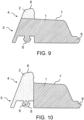
- Figure 9 shows a side view of a cross section of a center seal according to another embodiment of the invention.
- the profile seal is similar to the seals shown in Figure 1 or Figure 7
- the contact shoulder 6 of this embodiment is made of a foam rubber 2 or a foam rubber mixture 2.
- the contact shoulder 6 of this embodiment does not have an air channel 9.
- the profile seal does not have any air channels 9.
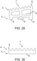
- Figure 10 shows a side view of a cross-section of a center seal according to another embodiment of the invention.
- This embodiment is similar to that shown in Figure 9 In contrast to the embodiment shown in Figure 9 In the embodiment shown, however, in this embodiment not only is the contact shoulder 6 made of a foam rubber 2 or a foam rubber mixture 2, but also the area of the profile seal which is located below the contact shoulder 6 and extends into the foot area 5.
- the profile seal has exactly one air duct 9.
- One air duct 9 has an elliptical shape, with the ellipse being arranged such that it extends in the vertical direction.
- One air duct 9 is located in the foot area 5 in a retaining knob 8 which is arranged in the area of the foot area 5 which is located below the contact shoulder 6.
- Figure 11 shows a side view of a cross-section of a center seal according to another embodiment of the invention.
- This embodiment is similar to that shown in Figure 10 In contrast to the embodiment shown in Figure 10 In the embodiment shown, this embodiment has, in addition to the one air channel 9 in the retaining knob 8, further additional air channels 9 in the contact shoulder 6, in the area below the contact shoulder 6 and in the area below the central web 7, wherein the shape and position of the additional air channels 9 correspond to the shape and position of the air channels 9 of the Figure 5 and Figure 8 correspond to the embodiments shown.
- Figure 12 shows a side view of a cross section of a central seal according to a further embodiment of the invention.
- the profile seal has a contact shoulder 6, which does not have an air channel 9.
- the profile seal has a central web 7, which has an almost semicircular elevation.
- the air duct 9, which is closer to the contact shoulder 6, has the shape of a rectangle with rounded corners, whereas the other air duct 9 has the shape of a trapezoid with rounded corners.
- the black-filled area in the figure corresponds to the part of the central seal which consists of the foam rubber 2 or a foam rubber mixture 2.
- the retaining stud 8 has an air duct 9, the shape of which corresponds to a rectangle with rounded corners, with the upper corners being more rounded than the lower ones.
- In the foot area 5 of the profile seal there is another retaining stud 8, without an air duct 9, arranged centrally.
- This retaining stud 8 is made of the elastomer composition 1 according to the invention and has the shape of a rectangle with rounded corners.
- This holding area 8 has a rectangular and a trapezoid-like elevation.
- Figure 13 shows a side view of a cross section of a central seal according to a further embodiment of the invention.
- the profile seal has a contact shoulder 6 and a central web 7.
- the profile seal has an opening in the shape of a triangle in the area below the contact shoulder 6 on the side which is designed to face away from the pane and towards a frame.
- the contact shoulder 6 has an opening on the side which is designed to face a pane. This opening extends into the area below the central web 7.
- the opening extends from the head region 4 to approximately the middle of the foot region 5 and is located centrally in the profile seal. At the lower end, the opening has a semicircular shape.
- the central web 7 further has two elongated elevations with a semicircular upper side.
- an air duct 9 which has the shape of a trapezoid with rounded corners.
- a Retaining area 8 which is made of a soft rubber 3 or a soft rubber compound 3 and has three approximately equal-sized air channels 9, which are rectangular in shape with rounded corners.
- the retaining area 8 extends almost across the entire width of the base area 5 or the profile seal.
- Figure 14 shows a side view of a cross-section of a central seal according to another embodiment of the invention.
- the profile seal has a contact shoulder 6 in the shape of a rectangle with rounded corners and a central web 7.
- the central web 7 has two elevations which have the shape of trapezoids with rounded corners. One elevation is located centrally on the central web 7. The other elevation is located at the edge of the central web 7, on the side opposite the contact shoulder 6.
- In the base area 5 there is a holding area 8 with a flat underside.
- the holding area 8 is made of soft rubber 3 or a soft rubber mixture 3 and extends across the entire width of the base area 5 or the profile seal.
- Below the central web 7 there are two air channels 9 which have the shape of trapezoids with rounded corners and a sloping top. The two air channels 9 extend into the base area 5 and into the holding area 8.
- Figure 15 shows a side view of a cross section of a central seal according to a further embodiment of the invention.
- the profile seal has a central web 7.
- the central web 7 has two semicircular elevations.
- a first semicircular elevation is located centrally on the central web 7.
- the second semicircular elevation is located between the first elevation and the outer edge of the profile seal, which is opposite the contact shoulder 6.
- the profile seal has a contact shoulder 6, which has a curvature and merges flatly, at an angle of 180°, into the central web 7.
- the contact shoulder 6 projects laterally beyond the rest of the profile seal.
- In the area below the central web 7 there are two air ducts 9.
- the first air duct 9, which is located closer to the side of the contact shoulder 6, has the Shape of a rectangle with rounded corners, wherein the side edge facing the outer edge of the profile seal has a concave curvature.
- a second air duct 9 Next to the first air duct 9 there is a second air duct 9.
- the second air duct 9 has the shape of a trapezoid with rounded corners.
- the contact shoulder 6 is made of soft rubber 3 or a soft rubber mixture 3.
- An outer edge of the outer edge of the profile seal, which extends from the contact shoulder 6 into the foot area 5 and across the entire width of the foot area 5, is made of soft rubber 3 or a soft rubber mixture 3.
- the foot area 5 has a holding area 8 which is made of soft rubber 3 or a soft rubber mixture 3 and extends across the entire width of the foot area 5.
- the holding area 8 has a semicircular elevation on the outer edge, which is on the same side as the contact shoulder 6. Next to this elevation, on the underside of the profile seal, there is another elevation in the shape of a rectangle with rounded corners.
- In the foot area 5 below the second elevation of the central web 7 there is an elevation in the shape of a trapezoid.
- an opening Directly next to this elevation, on the side facing away from the contact shoulder 6, there is an opening.
- a retaining stud 8 made of soft rubber 3 or a soft rubber mixture 3.
- the retaining stud 8 has an air channel 9 in the shape of a rectangle with rounded corners, whereby the side edge of the rectangle, which faces the outer edge of the profile seal, has a curve.
- Figure 16 shows a side view of a cross-section of a side seal according to another embodiment of the invention.
- the profile seal has a contact shoulder 6, which is made of a foam rubber 2 or a foam rubber mixture 2, wherein the area of the profile seal below the contact shoulder 6 also consists of foam rubber 2 or a foam rubber mixture 2.
- the profile seal has a central web 7, which has an opening.
- the central web 7 also has a raised portion.
- the raised portion is shaped like a hook or an upside-down letter "L".
- the side seal has no air channels 9.
- Figure 17 shows a side view of a cross-section of a side seal according to a further embodiment of the invention.
- the profile seal has a contact shoulder 6 and an area below the contact shoulder, which consist of foam rubber 2 or a foam rubber mixture 2.
- the side seal has a central web 7.
- the central web 7 has four elevations in the shape of triangles.
- Figure 18 shows a side view of a cross-section of a side seal according to a further embodiment of the invention.
- the profile seal has a central web 7.
- the central web 7 has wave-shaped elevations. One of the wave-shaped elevations extends such that it forms an upper part of the contact shoulder 6.
- the central web 7, the area below the central web 7 in the head region 4 of the profile seal, the wave-shaped elevations of the central web 7 and the upper part of the contact shoulder 6, as well as the outer edge of the profile seal, which faces away from the contact shoulder 6, are made of foam rubber 2 or a foam rubber mixture 2.
- the lower part of the contact shoulder 6 and the foot region 5 are made of the elastomer composition 1 according to the invention.
- the foot region 5 has a retaining knob 8 in the center. On the outer edge of the profile seal, on whose side the contact shoulder 6 is also located, there is a narrow elevation at the bottom, which extends in a vertical direction.
- Figure 19 shows a side view of a cross section of a side seal according to another embodiment of the invention.
- the embodiment is similar to that shown in Figure 18
- this embodiment has on the outer edge, which is facing away from the contact shoulder 6, a raised area made of foam rubber 2 or a Foam rubber mixture 2.
- the elevation has an elongated shape with a semicircular tip and extends horizontally, so that the elevation protrudes laterally beyond the profile seal.
- Figure 20 shows a side view of a cross-section of a side seal according to a further embodiment of the invention.
- the profile seal has a central web 7.
- the central web 7 has a triangular opening which extends across the entire width of the central web 7. The opening extends into the lower head region 4 and almost into the foot region 5 of the profile seal.
- the contact shoulder 6, the central web 7 and the outer edge of the opening of the central web 7 are made of foam rubber 2 or a foam rubber mixture 2.
- the area below the areas made of foam rubber 2 or foam rubber mixture 2 is made of the elastomer composition 1 according to the invention.
- the foot region 5 has a holding area 8. In the foot region 5 below the contact shoulder 6 there is a holding stud 8 in the shape of a trapezoid with rounded corners, whereas on the opposite side there is a holding stud 8 in the shape of a rounded triangle.
- Figure 21 shows a side view of a cross section of a side seal according to another embodiment of the invention.
- the embodiment shown is similar to that shown in Figure 20
- a holder 10 made of foam rubber 2 or a foam rubber mixture 2 is mounted in the base area 5 of this embodiment.
- the holder 10 is mounted on the outer edge of the profile seal, which faces away from the contact shoulder 6, and has an elongated shape with a semicircular tip, which projects laterally beyond the rest of the profile seal.
- Figure 22 shows a side view of a cross section of a side seal according to another embodiment of the invention.
- the embodiment shown is similar to that shown in Figure 20
- this embodiment has two further holders 10, which consist of the elastomer composition 1 according to the invention.
- Both holders 10 are mounted on the outer edge of the profile seal, which faces away from the contact shoulder 6, with one holder 10 being mounted in the head region 4 and the other in the foot region 5.
- Both holders 10 have an elongated shape with a semicircular tip, which projects laterally beyond the rest of the profile seal.
- Figure 23 shows a side view of a cross-section of an insulation strip according to an embodiment of the invention.
- the profile seal has a predominantly flat central web 7 with two semicircular elevations.
- the profile seal has a contact shoulder 6, which is located next to the central web 7 and has a semicircular shape.
- the outer edges of the profile seal are arranged at an angle so that the profile seal becomes wider towards the base area 5.
- the base area 5 has a holding area 8 in the area below the central web 7.
- the holding area 8 is designed as a holding knob, which has the shape of a rectangle with a trapezoid on the underside.
- the profile seal has nine air channels 9.
- a first air channel 9 is located below the contact shoulder 6 and has the shape of a trapezoid with rounded corners.
- a second air channel 9 which has the shape of a rectangle with rounded corners.
- a third, fourth, and fifth air duct 9 are rectangular in shape with a sloping top or upper edge and rounded corners.
- a sixth air duct 9 which has the shape of a trapezoid with rounded corners.
- a seventh, an eighth, and a ninth air duct 9 which extend into the holding area 8.
- the seventh air duct 9 is located below the fourth air duct 9, the eighth air duct 9 is located below the fifth air duct 9, and the ninth air duct 9 is located below the sixth air duct 9.
- the seventh and ninth air ducts 9 have a shape resembling a rectangle with rounded corners, in which The bottom, left, and right corners have been cut off, resulting in a pentagonal shape that is not a regular pentagon.
- the eighth air duct 9, located between the seventh and ninth air ducts 9, has the shape of a rectangle with rounded corners.
- Figure 24 shows a side view of a cross-section of an insulation strip according to a further embodiment of the invention.
- the profile seal has a contact shoulder 6 in the shape of a rectangle.
- the central web 7 has two elevations which extend perpendicular to the central web 7.
- Below the central web 7 there is a rectangular air duct 9.
- Below the contact shoulder 6 there is an opening which has the shape of a half ellipse.
- On the opposite side of the profile opening there is an elevation in the shape of a half ellipse which is congruent with the shape of the opening.
- In the foot area 5 of the profile seal there is a holding area 8 in the shape of a rectangle below the contact shoulder 6, the shape of the holding area 8 being congruent with the shape of the contact shoulder 6.
- Figure 25 shows a side view of a cross-section of an insulation strip according to an embodiment of the invention.
- the embodiment shown is similar to that shown in Figure 24 In contrast to the embodiment shown in Figure 24 In the embodiment shown, this embodiment has three elevations in the area of the central web 7 in the head region 4 and three holding regions 8 in the foot region 5, which extend vertically and whose shape is congruent with the shape of the elevations of the central web 7.
- the profile seal has two rectangular air channels 9.
- Figure 26 shows a side view of a cross section of an insulating strip according to another embodiment of the invention.
- the profile seal has a flat Central web 7.
- the contact shoulder 6 has the shape of a triangle with rounded corners.
- the outer edge of the profile seal opposite the contact shoulder 6 is arranged at an angle so that the profile seal becomes narrower towards the foot area 5.
- the outer edge of the profile seal opposite the contact shoulder 6 has a raised area in the shape of a trapezoid with rounded corners.
- the profile seal has a holding area 8 which extends almost across the entire width of the foot area 5 or the profile seal.
- the profile seal has three air ducts 9 below the central web 7, which are arranged next to one another.
- the first air duct 9, which is located near the contact shoulder, and the second air duct, which forms the central air duct, have the shape of a rectangle with a sloping top and rounded corners.
- the third air duct 9 is arranged on the side of the profile seal opposite the contact shoulder.
- the third air duct has the shape of a rectangle with rounded corners, with the two corners, which are located near the outer edge of the profile seal, each having an opening in the shape of a quarter circle.
- Figure 27 shows a side view of a cross-section of an insulation strip according to one embodiment of the invention.
- the profile seal has a predominantly flat central web 7 with two elevations in the shape of rectangles with rounded corners.
- the central web 7 has an opening in the shape of a triangle or a half-trapezoid with rounded corners.
- the profile seal has a narrow contact shoulder 6 with a rounded upper side, which extends almost vertically or slightly diagonally from the central web 7.
- the outer edge of the profile seal facing away from the contact shoulder has an elevation that extends diagonally from the outer edge of the profile seal.
- a first, a second, a third, and a fourth air duct 9 are arranged below the central web 7, wherein the air ducts 9 extend from the head region 4 of the profile seal to the foot region of the profile seal.
- the first air duct 9, which is located below the contact shoulder, and the second air duct 9, which is arranged next to the first air duct 9, have the shape of a rectangle with rounded corners.
- the third air duct 9, which is located next to the second air duct 9, has the shape of a rectangle with a sloping top and rounded corners.
- the fourth air duct 9, which is located next to the third air duct 9, has the shape of a trapezoid with rounded corners.
- the base area 5 of the profile seal has a holding area 8 designed as a holding knob, which has the shape of a rectangle with a trapezoid on the underside. Within this holding knob, two air ducts 9 are arranged next to one another, which have the shape of rectangles with rounded corners.
- the base area 5 also has a further holding area 8 on the opposite side, which includes a rectangular elevation. Between the already mentioned holding areas 8, a further holding area 8 is arranged, which has the shape of a rounded rectangle.
- Figure 28 shows a side view of a cross-section of an insulation strip according to one embodiment of the invention.
- the profile seal has a semicircular contact shoulder 6.
- the profile seal has a central web 7 with two semicircular elevations.
- the holding area 8 in the base area 5 of the profile seal is flat.
- the profile seal has no air channels 9.
- Figure 29 shows a side view of a cross-section of an insulation strip according to one embodiment of the invention.
- the profile seal has a central web 7 with adjacently arranged elevations in the shape of triangles with rounded corners.
- the profile seal has a contact shoulder 6, which does not differ significantly from the elevations of the central web 7.
- Below the central web 7 are two adjacently arranged air ducts 9.
- the air ducts have the shape of rectangles with a sloping top and rounded corners, which extend from the head region 4 to the foot region 5 of the profile seal.
- In the foot region 5 there are two rectangular holding areas 8, one of each of the holding areas 8 is arranged on an outer edge of the profile seal. Between these two holding areas 8 arranged on the outer edges there is a central holding area 8.
- the central holding area 8 is designed as a holding knob, which has the shape of a rectangle with a trapezoid on the underside.
- the foot area 5 below the two air ducts 9 arranged next to each other, there is another air duct 9 arranged centrally, which has the shape of a rectangle with rounded corners, which extends into the middle holding area 8.
- Figure 30 shows a side view of a cross-section of an insulation strip according to another embodiment of the invention.
- the profile seal has a central web 7 with adjacently arranged elevations in the shape of triangles with rounded corners. At the outer edges of the profile seal, the central web 7 has a narrower elevation or a narrow contact shoulder 6 compared to the other elevations.
- the holding area 8 in the base area 5 of the profile seal is flat. The outer edges of the profile seal run perpendicular to the holding area.
- Figure 31 shows a side view of a cross-section of an insulation strip according to an embodiment of the invention.
- the profile seal has a central web 7 with elevations in the shape of trapezoids with rounded corners.
- the profile seal has a contact shoulder 6, which does not differ significantly from the elevations of the central web 7.
- the outer edges of the profile seal run diagonally, so that the profile seal becomes narrower towards the holding area 8.
- the holding area 8 is flat.
- the invention also relates to a use of the profile seal according to the invention for thermal insulation, preferably for thermal insulation in the construction sector, in particular as a center seal, side seal, and/or insulating strip, for example in window frames or door frames.
- the profile seal can be used for thermal insulation of windows and doors, in particular building windows and doors.
- the profile seals, in particular the insulating strips, can be individually adapted to the respective profiles or profile systems, in particular to aluminum window systems and/or aluminum door systems.
- the above-mentioned material mixture is treated in an ultra-high frequency (UHF) system with ultra-high frequency microwaves and hot air at a temperature of 200-270 °C. Vulcanization of the material mixture produces a material comprising an elastomer composition.
- the material produced according to the invention has a compression hardness of 410 to 490 kPa, in particular 462.0 kPa, at a compression of 25%, 790 kPa to 870 kPa, in particular 836.8 kPa at a compression of 40%, and 1220 kPa to 1320 kPa, in particular 1284.0 kPa, at a compression of 50%.
- the material has a compression set of 50% at a compression of 25% at 70 °C for 24 hours, a compression set of 33% at a compression of 25% at 23 °C for 24 hours and a compression set of 60% at a compression of 25% for 24 hours at -10 °C.
- 20 phr of Expancel 930 DU 120 is used in the above-mentioned material mixture.
- the material which was obtained by vulcanization of the material mixture, has a compression hardness of 850 kPa, in particular 892.0 kPa, at a compression of 25%, 1580 kPa to 1660 kPa, in particular 1623.0 kPa, at a compression of 50% and 2490 kPa to 2560 kPa, in particular 2535.0 kPa, at a compression of 50%, according to ISO 3386.
- the material has a compression set of 52% at a compression of 25% for 24 hours at 70 °C, a compression set of 28% at a compression of 25% for 24 hours at 23 °C and a compression set of 55% at a compression of 25% for 24 hours at -10 °C.
Landscapes
- Chemical & Material Sciences (AREA)
- Engineering & Computer Science (AREA)
- Civil Engineering (AREA)
- Structural Engineering (AREA)
- Organic Chemistry (AREA)
- Health & Medical Sciences (AREA)
- Chemical Kinetics & Catalysis (AREA)
- Medicinal Chemistry (AREA)
- Polymers & Plastics (AREA)
- Materials Engineering (AREA)
- General Chemical & Material Sciences (AREA)
- Manufacture Of Porous Articles, And Recovery And Treatment Of Waste Products (AREA)
- Compositions Of Macromolecular Compounds (AREA)
Description
- Die vorliegende Erfindung betrifft eine hoch wärmedämmende Profildichtung aus einer Elastomerzusammensetzung, ein Verfahren zu deren Herstellung und die Verwendung der Profildichtung zur Wärmedämmung.
- Profildichtungen für die Wärmedämmung von Fenstern und Türen sind bereits bekannt. Bislang kommen vor allem Elastomer-Werkstoffe wie beispielsweise thermoplastische Elastomere (TPE), Silikon-Kautschuke, Ethylen-Propylen-Dien-Kautschuke (EPDM), Chloropren-Kautschuk (CR) und Polyvinylchlorid (PVC) zum Einsatz.
- Entscheidend für die Qualität einer Wärmedämmung ist der Wärmedurchgangskoeffizient (Uw-Wert). Der Wärmedurchgangskoeffizient Uw ist die Wärmemenge, welche pro Zeiteinheit (üblicherweise 1 Sekunde) durch 1 m2 eines Bauteils (beispielsweise Mauer, Beton, Dach) bei einem Temperaturunterschied von 1 Kelvin (K) hindurchgeht. Der Uw-Wert stellt somit eine Maßeinheit für den Wärmeverlust dar. Je geringer der Uw-Wert ist, desto geringer ist der Wärmeverlust und desto besser ist die Wärmedämmeigenschaft eines Bauteils. Für eine gute Wärmedämmung und gute Isoliereigenschaften ist somit ein möglichst kleiner Uw-Wert erwünscht.
- Bei der Berechnung des Uw-Wertes für ein Fenster oder eine Tür muss berücksichtigt werden, dass das Fenster oder die Tür aus mehreren Bestandteilen, insbesondere aus einer Verglasung und einem Rahmen, besteht.
- Der Uw-Wert des Fensters oder der Tür ergibt sich aus den jeweiligen Uw-Werten der einzelnen Bestandteile unter Berücksichtigung der jeweiligen Flächenanteile, die diese einnehmen.
- Nach der EnEV 2009 darf bei normaler Verglasung der Uw-Wert 1,3 Watt pro Quadratmeter und Kelvin (W/(m2·K)) nicht überschreiten. Fenster mit einem Uw-Wert von 0,9 W/(m2·K) gelten als Fenster mit effizienter Wärmedämmung. Als passivhaustauglich werden Fenster mit einem Uw-Wert von 0,8 W/(m2·K) oder kleiner angesehen.
- Um mittels einer hoch wärmedämmenden Profildichtung eine gute Wärmedämmung eines Fensters oder einer Tür zu erreichen, sollte die Profildichtung aus einem Material mit niedriger Wärmeleitfähigkeit λ gefertigt sein. Die Wärmeleitfähigkeit λ entspricht dem Wärmefluss, welcher ein Objekt mit einer Oberfläche von 1 m2 und einer Dicke von 1 m, bei einer Temperaturdifferenz von 1 K pro Sekunde passiert. Derzeit wird laut DIN EN 10077 für Uw-Wert Berechnungen für Profildichtungen eine Wärmeleitfähigkeit λ = 0,05 Watt pro Meter und Kelvin (W/(m·K)) angenommen. Jedoch wird diese Wärmeleitfähigkeit von 0,05 W/(m·K) bisher nur von Materialien mit einer Dichte von 0.06-0.08 g/cm3 erreicht. Diese Materialien haben jedoch eine niedrige Stauchhärte von meist unter 300 kPa bei 50 % Kompression (d.h. Stauchung), was deren Anwendung im Baubereich limitiert. Die handelsüblichen Baustoffe für Profildichtungen weisen eine höhere Dichte und eine höhere Wärmeleitfähigkeit auf. Beispielsweise beträgt die Wärmeleitfähigkeit von PVC 0,14-0,17 W/(m·K) bei einer Dichte von etwa 1,20-1,40 g/cm3 und von Silikonen etwa 0,2-0,3 W/(m·K) bei einer Dichte von etwa 0,76-1,07 g/cm3 bzw. 0,05 W/(m·K) bei einer Dichte von 0,2 g/cm3.
- Aus dem Stand der Technik ist die Verwendung von Mikrohohlkugeln zur Verringerung der Dichte von Materialien für Dichtungen bekannt.
JP H08 12797 A - Aus der
US 2013/0072584 A1 sind Dichtungsleisten für Kraftfahrzeuge, umfassend ein Hauptkörperelement aus einem Material hoher Dichte und einen Schwammkörper aus einem komprimierbaren Material, bekannt, wobei der Schwammkörper Gummi und expandierbare Mikrokugeln als physikalisches Blähmittel enthält. - Es ist jedoch bislang keine Profildichtung aus einem Material bekannt, welches die in der DIN EN 10077 angenommene Wärmeleitfähigkeit λ = 0,05 W/(m·K) erreicht und zugleich ein elastisches Verhalten und eine hohe Steifigkeit bei geringer Dichte aufweist.
- Daher ist es Aufgabe der vorliegenden Erfindung, eine Profildichtung mit verbesserten Wärmedämmeigenschaften, insbesondere mit einer Wärmeleitfähigkeit λ < 0,060 W/(m·K), bereitzustellen, welche sich für eine Dauerfunktion eignet und eine hohe Elastizität, ein gutes Rückstellvermögen sowie eine hohe Steifigkeit bei geringer Dichte aufweist.
- Diese Aufgabe wird durch eine Profildichtung gemäß Anspruch 1 gelöst.
- Eine erfindungsgemäße Profildichtung, insbesondere für Fenster und Türen, umfasst eine Elastomerzusammensetzung, enthaltend
- 100 phr Elastomer und
- 25-40 phr expandierte Mikrokugeln,
- wobei der mittlere Durchmesser der expandierten Mikrokugeln 10-200 µm beträgt und die Elastomerzusammensetzung eine Dichte von 0,10-0,30 g/cm3 aufweist.
- Der hohe Anteil von 25-40 phr expandierten Mikrokugeln mit einem mittleren Durchmesser der expandierten Mikrokugeln von 10-200 µm sorgt für eine geringe Dichte und eine geringe Wärmeleitfähigkeit der Elastomerzusammensetzung und überraschenderweise gleichzeitig für eine hohe Steifigkeit des Materials sowie eine hohe Elastizität und ein gutes Rückstellvermögen des Materials. Dies war bislang nicht erreichbar, insbesondere nicht mit chemischen Treibmitteln.
- Die Aufgabe wird weiter gelöst durch ein Verfahren zur Herstellung einer Profildichtung gemäß Anspruch 14.
- Ein Verfahren zur Herstellung einer Profildichtung umfasst die Schritte, dass eine Werkstoffmischung, umfassend 100 phr Elastomer und 25-40 phr expandierbare Mikrokugeln, auf eine Temperatur von 75 - 300 °C erhitzt und eine Profildichtung geformt wird. Beim Erhitzen expandieren die expandierbaren Mikrokugeln und bilden expandierte Mikrokugeln. Die "Werkstoffmischung" bezeichnet das Ausgangsmaterial, das erhitzt wird und expandierbare Mikrokugeln enthält, und die "Elastomerzusammensetzung" das nach dem Erhitzen erhältliche Material, das expandierte Mikrokugeln enthält.
- Die Profildichtung für Fenster und Türen kann insbesondere eine Profildichtung für Gebäude-Fenster, Gebäude-Türen und Gebäude-Tore sein, d. h. als Gebäude-(Fenster-/Tür-/Tor-)Profildichtung ausgebildet sein.
- Weitere Vorteile und Merkmale ergeben sich aus den jeweiligen Unteransprüchen, sowie aus der Beschreibung und den Figuren.
- Erfindungsgemäß umfasst die Profildichtung ein Elastomer, um eine hohe Elastizität zu erreichen, sowie expandierte Mikrokugeln, welche eine hohe Steifigkeit und niedrige Dichte, sowie eine niedrige Wärmeleitfähigkeit ermöglichen.
- Eine Dichtung kann ein Element oder eine Konstruktion sein, welche(s) dazu ausgelegt ist, einen ungewollten Stoff- oder Wärmeübergang von einem Ort zu einem anderen Ort zu verhindern oder zu begrenzen.
- Die Profildichtung kann eine Dichtung in Form eines Profilkörpers sein, welcher sich in eine Längsrichtung bzw. Profilrichtung erstreckt und dessen Querschnitt eine gewisse geometrische Form aufweist. Bevorzugt ändert sich die geometrische Form des Querschnitts über die Längsrichtung bzw. Profilrichtung nicht, sodass die Querschnittsflächen des Profilkörpers in Längsrichtung an jeder Position deckungsgleich sind.
- Die Profildichtung kann als eine Mitteldichtung, Seitendichtung und/oder als Dämmstreifen ausgebildet sein.
- Die Profildichtung kann durch Extrusion, Kalandrieren oder Pressung hergestellt werden. Extrusion ist ein Verfahren, bei welchem ein plastisch verformbares, dickflüssiges Material unter Druck kontinuierlich aus einer formgebenden Öffnung gepresst wird. Die formgebende Öffnung kann eine Matrize, eine Düse oder ein Mundstück sein. Die geformte Masse kann nach dem Austritt aus der formgebenden Öffnung durch Abkühlung aushärten. Vorteil der Extrusion ist, dass damit Profilkörper mit komplexen Querschnittsformen in nahezu beliebiger Länge hergestellt werden können. Kalandrieren ist ein Verfahren, bei welchem ein Material durch ein System aus mehreren übereinander angeordneten Walzen hindurchgeführt wird. Pressung ist ein Verfahren, bei welchem ein Material zwischen zwei Festkörpern, bevorzugt Platten, eingebracht wird und die beiden Festkörper aufeinander zubewegt werden, sodass eine Kraft auf das Material zwischen den beiden Festkörpern ausgeübt wird.
- Gemäß einem weiteren Aspekt der Erfindung weist die Elastomerzusammensetzung, aus der die Profildichtung gebildet ist, eine Dichte von 0,10-0,30 g/cm3, bevorzugt von 0,12-0,28 g/cm3 und am meisten bevorzugt von 0,17-0,26 g/cm3 auf. Mit diesen Dichten lassen sich besonders niedrige Wärmeleitfähigkeiten des Materials erreichen.
- Die erfindungsgemäße Elastomerzusammensetzung umfasst 25-40 phr, bevorzugt 25-38 phr expandierte Mikrokugeln. Mit diesen Anteilen an expandierte Mikrokugeln lässt sich überraschenderweise eine besonders geringe Wärmeleitfähigkeit der Elastomerzusammensetzung bei gleichzeitig hoher Steifigkeit des Materials, einer hohen Elastizität und einem guten Rückstellvermögen des Materials erreichen.
- In einer bevorzugten Ausführungsform der Erfindung umfasst die Elastomerzusammensetzung zusätzlich
- 10-150 phr Weichmacher
- 20-400 phr Füllstoff
- 0-100 phr chemisches Treibmittel
- 1-50 phr Hilfsstoff und
- 0-30 phr Trocknungsmittel sowie optional
- 1-30 phr, bevorzugt 3-12 phr, besonders bevorzugt 5-10 phr Vernetzer.
- Erfindungsgemäß umfasst die Werkstoffmischung zur Herstellung der erfindungsgemäßen Profildichtung aus einer Elastomerzusammensetzung:
- 100 phr Elastomer
- 0-300 phr, bevorzugt 10-150 phr, besonders bevorzugt 20-100 phr, Weichmacher
- 0-600 phr, bevorzugt 20-400 phr, besonders bevorzugt 50-180 phr, Füllstoff
- 0-30 phr, bevorzugt 1-30 phr, weiter bevorzugt 3-12 phr, besonders bevorzugt 5-10 phr, Vernetzer
- 25-40 phr, bevorzugt 25-38 phr expandierbare Mikrokugeln
- 0-100 phr, bevorzugt 1-15 phr, besonders bevorzugt 5-10 phr, chemisches Treibmittel
- 0-100 phr, bevorzugt 1-50 phr, besonders bevorzugt 1-10 phr, Hilfsstoff
- 0-30 phr, bevorzugt 1-20 phr, besonders bevorzugt 2-10 phr, Trocknungsmittel.
- Die Herstellung der erfindungsgemäßen Profildichtung aus einer Elastomerzusammensetzung erfolgt durch Erhitzen der Werkstoffmischung auf eine Temperatur von 75-300 °C, bevorzugt 200-280 °C, bevorzugter 210-270 °C und Formen einer Profildichtung, beispielsweise durch Extrudieren, Kalandrieren oder Pressen. Beim Erhitzen erfolgt die Expansion der expandierbaren Mikrokugeln zu expandierten Mikrokugeln. Wenn Vernetzer in der Werkstoffmischung enthalten ist, kann ferner eine Vernetzung des Elastomers stattfinden.
- Die Profildichtung, insbesondere für Fenster- und Türen, ist erfindungsgemäß aus einer Elastomerzusammensetzung, umfassend:
- 100 phr Elastomer
- 0-300 phr, bevorzugt 10-150 phr, besonders bevorzugt 20-100 phr, Weichmacher
- 0-600 phr, bevorzugt 20-400 phr, besonders bevorzugt 50-180 phr, Füllstoff
- 25-40 phr, bevorzugt 25-38 phr expandierte Mikrokugeln
- 0-100 phr, bevorzugt 1-15 phr, besonders bevorzugt 5-10 phr, chemisches Treibmittel
- 0-100 phr, bevorzugt 1-50 phr, besonders bevorzugt 1-10 phr, Hilfsstoff
- 0-30 phr, bevorzugt 1-20 phr, besonders bevorzugt 2-10 phr, Trocknungsmittel.
- Vorzugsweise enthält die Elastomerzusammensetzung 1-30 phr, weiter bevorzugt 3-12 phr, besonders bevorzugt 5-10 phr, Vernetzer.
- Unter phr (parts per hundred rubber) wird wie üblich der Massenanteil der einzelnen Komponenten einer elastomeren Zusammensetzung bezeichnet, wobei die Angaben jeweils auf 100 Massenteile des Elastomers bezogen sind.
- Die Angabe phr kann in dem Fachmann bekannter Weise auch in Gewichtsprozent umgerechnet werden. Dazu werden die Massen der einzelnen Komponenten durch die Gesamtmasse der Zusammensetzung dividiert. Eine Zusammensetzung mit beispielsweise 100 phr Elastomer, 10 phr Weichmacher und 10 phr expandierbaren Mikrokugeln entspräche einer Zusammensetzung mit 83,3 Gew.-% Elastomer, 8,3 Gew.-% Weichmacher und 8,3 Gew.-% expandierbaren Mikrokugeln.
- Das Elastomer kann ein Elastomer oder ein Elastomerverschnitt (Elastomermischung) sein. Bevorzugt handelt es sich bei dem Elastomer in dieser Werkstoffmischung oder Elastomerzusammensetzung um EPM (Ethylen-Propylen Copolymer), EPDM (Ethylen-Propylen-Dien Kautschuk) oder Verschnitte (Mischungen) aus EPDM und BR (Butadien-rubber, d.h. Polybutadien). Das Elastomer bewirkt eine hohe Elastizität und eine hohe Witterungsbeständigkeit der Profildichtung.
- Die Werkstoffmischung zur Herstellung der Profildichtung umfasst in einer bevorzugten Ausführungsform neben dem Elastomer auch Vernetzer, zum Beispiel 1-30 phr Vernetzer. Der Vernetzer regiert beim Erhitzen/Vulkanisieren mit dem Elastomer und bildet so ein Elastomer, das stärker vernetzt ist. Dabei wird der Vernetzer in das Elastomer eingebaut und ist so Teil des Elastomers der Elastomerzusammensetzung, die die Profildichtung bildet. Daher ist der Vernetzer in der erfindungsgemäßen Elastomerzusammensetzung nicht als separate Komponente aufgeführt.
- Wenn man das Elastomer und den Vernetzer auch in reagierter Form als separate Komponenten betrachtet, wäre die erfindungsgemäße Profildichtung wie folgt zusammengesetzt. Profildichtung, insbesondere für Fenster und Türen, vorzugsweise aus einer Elastomerzusammensetzung, umfassend:
- 100 phr Elastomer,
- 25-40 phr expandierte Mikrokugeln, und
- 1-30 phr, bevorzugt 3-12 phr, besonders bevorzugt 5-10 phr, eines Vernetzers,
- wobei der mittlere Durchmesser der expandierten Mikrokugeln 10-200 µm beträgt und die Elastomerzusammensetzung eine Dichte von 0,10-0,30 g/cm3 aufweist.
- Der Weichmacher kann ein Öl, insbesondere ein Mineralöl, ein pflanzliches Öl und/oder ein Polymer umfassen. Das Polymer kann ein Polyisobutylen umfassen. Der Weichmacher ermöglicht eine Optimierung der Viskosität der Elastomerzusammensetzung und eine Einstellung der Härte der Profildichtung. Es können mehrere verschiedene Weichmacher in einer Elastomerzusammensetzung verwendet werden.
- Der Füllstoff kann ein Stoff sein, welcher der Elastomerzusammensetzung zur Optimierung der Eigenschaften zugegeben werden kann. Als Füllstoff kann beispielsweise Ruß, Kaolin, Kreide oder Silica verwendet werden. Ferner können auch polymere Füllstoffe verwendet werden. Polymere Füllstoffe können Polypropylen und/oder Polyethylen umfassen. Als flammhemmende Füllstoffe können Aluminiumhydroxid, Magnesiumhydroxid und/oder Antimontrioxid verwendet werden. Ferner können Leichtfüllstoffe, die poröse Materialien wie beispielsweise Perlit umfassen, eingesetzt werden. Beispielsweise können Aeropor 180 (Hohlkugeln auf Aluminium-Silikat-Basis), Sil-cel (expandiertes Perlit) und/oder Cenospheres (Hohlkugeln auf Aluminium-Silikat-Basis) und/oder leichtgewichtige Kugeln ("light bubbles", z. B. Borosilikatglas-Kugeln) eingesetzt werden. Es können mehrere Füllstoffe in einer Werkstoffmischung oder Elastomerzusammensetzung verwendet werden. Füllstoffe haben den Vorteil, die Extrudierbarkeit der Werkstoffmischung bzw. Elastomerzusammensetzung zu erhöhen. Ferner können Füllstoffe die mechanischen Eigenschaften der Profildichtung verbessern. Insbesondere können Füllstoffe die Steifigkeit der Profildichtung erhöhen und die Wärmeleitfähigkeit erhalten oder senken.
- Der Vernetzer kann eine Substanz oder eine Mischung von Substanzen sein, welche eine vollständige oder teilweise Vernetzung der Polymerketten des Elastomers oder Elastomerverschnitts bewirkt. Der Vernetzer kann insbesondere ein Vernetzersystem sein, umfassend Schwefel und/oder Peroxid, Beschleuniger und/oder Aktivatoren, und/oder ein Harzsystem. Ein Peroxid kann bevorzugt eine organische Peroxidverbindung oder eine Mischung an organischen Peroxidverbindungen sein. Peroxide haben den Vorteil, den Vernetzungsgrad der Polymerketten und die Steifigkeit der Profildichtung erhöhen. Der Aktivator kann eine Substanz sein, welche die zu vernetzenden Polymerketten und/oder den Vernetzer aktiviert. Der Aktivator kann Stearinsäure oder Zinkoxid sein. Der Aktivator hat den Vorteil, eine effiziente Vernetzung von Polymerketten zu ermöglichen. Der Beschleuniger kann eine oder eine Mischung aus mehreren Substanzen sein, die die Vernetzungsrate (Geschwindigkeit der Vernetzung) erhöhen. Der Beschleuniger kann 2-Mercaptobenzothiazol (MBT) und/oder Tetramethylthiuramdisulfid (TMTD) sein. Der Beschleuniger hat den Vorteil, den Vernetzungsgrad der Polymerketten zu erhöhen und die Steifigkeit der Profildichtung zu erhöhen. In einer Werkstoffmischung können mehrere verschiedene Vernetzer, Vernetzungssysteme, Aktivatoren und/oder Beschleuniger eingesetzt werden. Vernetzer, Vernetzungssysteme, Aktivatoren und/oder Beschleuniger haben den Vorteil, die Steifigkeit der Profildichtung zu erhöhen. Durch Wahl eines optimalen Verhältnisses an Vernetzer, Vernetzungssystem, Aktivatoren und/oder Beschleunigern kann ein optimaler Vernetzungsgrad der Polymerketten, eine hohe Steifigkeit und hohe Elastizität der Profildichtung und ein optimales Treibverhalten der chemischen und physikalischen Treibmittel erreicht werden.
- Unter expandierbaren Mikrokugeln werden im Sinne der Erfindung mikroskopische Kugeln verstanden, d. h. im Wesentlichen kugelförmige Körper mit einem mittleren Durchmesser im Mikrometerbereich, insbesondere mit einem mittleren Durchmesser von 1-100 µm, bevorzugt 5-50 µm, besonders bevorzugt 6-40 µm, die eine Hülle aus thermoplastischem Material aufweisen und innerhalb der Hülle eine flüchtige organische Verbindung aufweisen, die als Treibmittel fungieren kann.
- Die flüchtige organische Verbindung ist vorzugsweise eine organische Verbindung, bevorzugt ein Kohlenwasserstoff, mit einem Siedepunkt < 120°C, weiter bevorzugt < 100°C, noch weiter bevorzugt < 60°C, am meisten bevorzugt < 40°C. Der Siedepunkt ist vorzugsweise unter der sogenannten Treibtemperatur. Die Treibtemperatur ist eine Temperatur, die hoch genug ist, um die thermoplastische Hülle zu erweichen und den Dampfdruck des Treibmittels zu erhöhen, sodass die Mikrokugeln expandieren. Die Expansion führt zu einer Volumenvergrößerung um mindestens das Zweifache, bevorzugt um das Zwanzig- bis Achtzigfache.
- Nach dem Expandieren bezeichnet man die expandierbaren Mikrokugeln als expandierte Mikrokugeln. Die Werkstoffmischung enthält daher expandierbare Mikrokugeln und die daraus hergestellte Elastomerzusammensetzung expandierte Mikrokugeln. Unter expandierten Mikrokugeln werden somit im Sinne der Erfindung vorzugsweise Mikrokugeln verstanden mit einer Hülle, bevorzugt einer geschlossenen Hülle, aus thermoplastischen Material, wobei sich im Innern der Hülle eine organische Verbindung befindet. Die organische Verbindung hat bevorzugt einen Siedepunkt < 120°C, weiter bevorzugt < 100°C, noch weiter bevorzugt < 60°C, am meisten bevorzugt < 40°C. Die organische Verbindung ist bevorzugt ein Kohlenwasserstoff, zum Beispiel Isopentan.
- Das thermoplastische Material, insbesondere ein thermoplastischer Kunststoff, ist vorzugsweise ein Polymer auf der Basis von Poylacrylnitril, Polystyrol und/oder PVC. Die expandierbaren Mikrokugeln weisen bevorzugt eine Treibtemperatur von 25 °C bis 300 °C, bevorzugt von 100 °C bis 290 °C, am meisten bevorzugt 200 °C bis 280 °C auf. Expandierbare Mikrokugeln mit einer Treibtemperatur von 25 bis 300 °C ermöglichen eine Expansion der Mikrokugeln beim Erhitzen der Werkstoffmischung. Die flüchtigen Kohlenwasserstoffverbindungen wirken als Treibmittel und bewirken eine besonders effektive Expansion der Mikrohohlkugeln.
- Unter Wärmeeinwirkung kann die thermoplastische Hülle erweichen. Bei Erreichen des Siedepunkts der Kohlenwasserstoffverbindung erfolgt eine Verdampfung, wodurch das Volumen, das die Kohlenwasserstoffverbindung einnimmt, zunimmt und ein Ausdehnen der Mikrokugeln bewirkt. Der mittlere Durchmesser der expandierbaren Mikrokugeln beträgt 1-100 µm, bevorzugt 5-50 µm, besonders bevorzugt 6-40 µm. Nach der Wärmeeinwirkung und dem Expandieren der expandierbaren Mikrokugel liegt eine expandierte Mikrokugel oder Mikrohohlkugel vor. Die expandierten Mikrokugeln oder Mikrohohlkugeln haben einen mittleren Durchmesser von 10-200 µm, bevorzugt 30-170 µm, weiter bevorzugt 40-150 µm, am meisten bevorzugt 50-130 µm.
- Der mittlere Durchmesser der expandierten Mikrokugeln wird ermittelt, indem in einem Schnitt durch die Elastomerzusammensetzung unter dem Mikroskop (z.B. einem Lichtmikroskop) der Durchmesser von mindestens 20 expandierten Mikrokugeln ausgemessen und der arithmetische Mittelwert bestimmt wird. Bei nicht ganz kugelförmigen Mikrokugeln wird dabei zufällig ein Durchmesser ausgewählt. Bei dieser Messung der Durchmesser der expandierten Mikrokugeln in einem Schnitt durch die Elastomerzusammensetzung werden nicht die tatsächlichen Durchmesser ermittelt, sondern die Durchmesser in einem (zufälligen) Schnitt und diese Durchmesser sind geringer als die tatsächlichen Durchmesser, weil ein zufälliger Schnitt überwiegend nicht durch den Mittelpunkt der Kugeln geht. Die mit der oben beschriebenen Messmethode in einem Schnitt ermittelten mittleren Durchmesser ergeben aber die angegebenen Bereiche der mittleren Durchmesser der expandierten Mikrokugeln.
- Der mittlere Durchmesser der expandierbaren Mikrokugeln, d.h. der Mikrokugeln vor dem Schritt des Expandierens ist bei kommerziell erhältlichen Produkten in der Regel angegeben. Er kann ermittelt werden, indem der Durchmesser von mindestens 20 expandierbaren Mikrokugeln ausgemessen wird, beispielsweise unter dem Mikroskop, und der arithmetische Mittelwert bestimmt wird.
- Die durchschnittliche Dicke der Hülle der expandierbaren Mikrokugeln ist bevorzugt 1 - 3 µm, besonders bevorzugt 1,5 - 2,5 µm. Die durchschnittliche Dicke der Hülle der expandierten Mikrokugeln ist bevorzugt 0,02 - 0,5 µm, besonders bevorzugt 0,05 - 0,3 µm, am meisten bevorzugt 0,08 - 0,2 µm.
- Die expandierten Mikrokugeln oder Mikrohohlkugeln haben den Vorteil, dass damit in der erfindungsgemäßen Elastomerzusammensetzung, die die Profildichtung bildet, eine niedrige Dichte der Elastomerzusammensetzung bzw. des Materials der Profildichtung erreicht werden kann und gleichzeitig noch eine hohe Steifigkeit des Materials vorliegt.
- Als expandierbare Mikrokugeln können zum Beispiel Expancel® Mikrosphären, beispielsweise Expancel 930 DU 120 verwendet werden. Die expandierbaren Mikrokugeln können eine Polymerhülle, welche PAN (Polyacrylnitril) umfasst, aufweisen. Beispielweise kann die Polymerhülle aus Polystyrol und PAN (als Copolymer) bestehen. Die Treibtemperatur hängt von der Erweichungstemperatur der Polymerhülle ab. Für Expancel® Mikrosphären kann als organisches Lösungsmittel Isopentan (Siedepunkt 28 °C) verwendet werden. Die Expancel® Mikrosphären haben im expandierten Zustand in der Regel einen Durchmesser von etwa 120 µm. Die expandierbaren Mikrokugeln dienen als physikalisches Blähmittel, welches zur Porenbildung und Senkung der Dichte eingesetzt wird. Die Größe der dabei entstehenden Poren entspricht in etwa der Größe der expandierten Mikrokugeln, weshalb der Porendurchmesser ≤200 µm, bevorzugt <150 µm und bevorzugter <130 µm beträgt, insbesondere beträgt der mittlere Durchmesser der Poren 10-200 µm, bevorzugt 30-170 µm, weiter bevorzugt 40-150 µm, am meisten bevorzugt 50-130 µm.
- Der zusätzliche Vorteil von expandierten Mikrokugeln bzw. physikalischen Blähmitteln ist, dass kleinere Porendurchmesser und somit eine feinere Porenstruktur erreicht werden können als mit chemischen Treibmitteln. Ferner kann durch die Verwendung von expandierbaren Mikrokugeln einfach und genau die Porengröße eingestellt werden. Der Vorteil der expandierbaren Mikrokugeln liegt überraschenderweise darin, dass damit bei gleicher Dichte eine höhere Steifigkeit der Profildichtung erreicht werden konnte als mit chemischen Treibmitteln und eine Wärmeleitfähigkeit der Elastomerzusammensetzung der Profildichtung von λ < 0,060 W/(m·K) erreicht werden konnte.
- Zusätzlich zu den Mikrokugeln kann ein chemisches Treibmittel eingesetzt werden. Ein chemisches Treibmittel kann eine Substanz sein, welche sich bei einer bestimmten Temperatur unter Abgabe eines Gases, beispielsweise Kohlenstoffdioxid, zersetzt. Als chemische Treibmittel können beispielsweise Isocyanat, Wasser, Azodicarbonamid, Hydrazin, insbesondere p-Toluolsulfonylhydrazid (TSH), und/oder 4,4'-Oxydi(benzolsulfonohydrazid) (OBSH) und/oder Natriumbicarbonat eingesetzt werden. Die erfindungsgemäße Werkstoffmischung kann kein chemisches Treibmittel, ein chemisches Treibmittel oder eine Mischung aus verschiedenen chemischen Treibmitteln enthalten. Vorteil des chemischen Treibmittels bzw. der chemischen Treibmittel ist die Verringerung der Dichte der Profildichtung durch Porenbildung.
- Der Hilfsstoff kann ein Alterungsschutzmittel, ein Vulkanisations-Verzögerer, ein Harz und/oder ein Verarbeitungshilfsmittel sein. Der Hilfsstoff kann der Werkstoffmischung zur Optimierung der Verarbeitungseigenschaften und der Oberflächenbeschaffenheit der Profildichtung zugegeben werden. Das Verarbeitungshilfsmittel kann Vaseline, Faktis (=künstlicher Kautschuk, Ölkautschuk), Paraffinwachs, Zinksalz, eine Fettsäure, ein Fettalkohol, ein Fettsäureester, Fettsäureamid, Polyolefin-Wachs und/oder Stearinsäure sein. In einer Werkstoffmischung können mehrere verschiedene Verarbeitungshilfsmittel eingesetzt werden. Vorteil des Verarbeitungshilfsmittels ist die einfache, kostengünstige Verarbeitung der Werkstoffmischung und die Vermeidung von Defekten, wie unerwünschte Gaseinschlüsse in der Profildichtung, welche die Steifigkeit und/oder Elastizität der Profildichtung verringern können.
- Das Trocknungsmittel kann eine Substanz sein, welche dazu geeignet ist, Feuchtigkeit aufzunehmen. Als Trocknungsmittel kann Calciumchlorid (CaCl2), wasserfreies Magnesiumsulfat (MgSO4), wasserfreies Calciumsulfat (CaSO4), Silicagel, Zeolithe und vorzugsweise Calciumoxid (CaO), eingesetzt werden. In der Werkstoffmischung können mehrere verschiedene Trocknungsmittel eingesetzt werden. Das Trocknungsmittel hat den Vorteil, unerwünschte Feuchtigkeit in der Werkstoffmischung zu verringern und die Lebensdauer der Profildichtung zu erhöhen.
- Gemäß einer Ausführungsform wird die Werkstoffmischung auf eine Temperatur von 75-300 °C, bevorzugt 200-280 °C, bevorzugter 210-270 °C erhitzt. Bei einer Temperatur von 75-300 °C kann eine Vulkanisation der Werkstoffmischung und eine Expansion der Mikrokugeln erfolgen. Vorteil des Temperaturbereichs von 75-300 °C ist eine einfache Durchführung des Verfahrens ohne strenge Temperaturkontrolle. Vorteil des Temperaturbereichs von 200-280 °C ist die kontrollierte Expansion der Mikrokugeln und die verbesserte Steifigkeit der Profildichtung. Der Temperaturbereich von 210-270 °C ermöglicht eine gleichmäßige und kontrollierte Expansion der Mikrokugeln und eine optimale Steifigkeit der Profildichtung und eine niedrige Wärmeleitfähigkeit der Profildichtung.
- Gemäß einer weiteren Ausführungsform ist die Werkstoffmischung extrudierbar, kalandrierbar und/oder pressbar. Die Werkstoffmischung kann durch Extrudieren, Kalandrieren oder Pressung geformt werden. Besonders bevorzugt erfolgt das Formen der Werkstoffmischung durch Extrusion. Vorteil der extrudierbaren, kalandrierbaren und/oder pressbaren Werkstoffmischung ist, dass eine Bearbeitung, insbesondere eine Formgebung, der Werkstoffmischung trotz der hohen Steifigkeit der Profildichtung ermöglicht wird. Eine Formung der Werkstoffmischung wird im großen Maßstab mit industriellen Methoden ermöglicht.
- Gemäß einer Ausführungsform erfolgt das Extrudieren, Kalandrieren oder die Pressung der Werkstoffmischung während des Erhitzens, vorzugsweise während der Vulkanisation.
- Gemäß einem Aspekt der Erfindung weist die Elastomerzusammensetzung, aus der die Profildichtung gebildet ist, eine Wärmeleitfähigkeit λ < 0,060 W/(m·K), bevorzugter λ < 0,057 W/(m·K), noch bevorzugter < 0,050 W/(m·K) und am bevorzugtesten < 0,045 W/(m·K) auf.
- Die Profildichtung umfasst die erfindungsgemäße Elastomerzusammensetzung. Die Profildichtung kann ganz oder teilweise aus der Elastomerzusammensetzung gefertigt werden. Die Elastomerzusammensetzung kann durch Verarbeitung der erfindungsgemäßen Werkstoffmischung hergestellt werden. Die erfindungsgemäße Elastomerzusammensetzung kann insbesondere durch Vulkanisation der Werkstoffmischung hergestellt werden. Ferner kann erfindungsgemäße Elastomerzusammensetzung durch Extrusion und/oder Kalandrieren der Werkstoffmischung hergestellt werden.
- Die Profildichtung kann ganz (zu 100 %) oder zu einem Teil (z. B. 10 %, 50 % oder 80 %) aus der erfindungsgemäßen Elastomerzusammensetzung bestehen.
- Gemäß einer weiteren Ausführungsform weist die erfindungsgemäße Elastomerzusammensetzung, aus welchem die Profildichtung zumindest teilweise besteht, eine hohe Stauchhärte auf. Die Stauchhärte der erfindungsgemäßen Elastomerzusammensetzung kann bei einer Kompression (d.h. Stauchung) eines Prüfkörpers gemessen werden. Die Stauchhärte kann beispielsweise bei einer Kompression von 25 % gemessen werden. Das bedeutet, dass die Höhe eines Prüfkörpers während der Krafteinwirkung um 25 % geringer ist als vor der Krafteinwirkung. Die Kraft bzw. der Druck kann in Kilo-Pascal (kPa) angegeben werden. Der Prüfkörper kann ein quadratischer Prüfkörper sein. Der Prüfkörper kann aus der erfindungsgemäßen Werkstoffmischung bestehen bzw. diese umfassen. Die Stauchhärte kann nach ISO 3386 bestimmt werden, indem der Prüfkörper zwischen zwei Platten um einen gewissen Prozentsatz komprimiert wird und die dazu notwendige Kraft gemessen wird. Die erfindungsgemäße Elastomerzusammensetzung weist vorzugsweise eine Stauchhärte von mindestens 100 kPa, bevorzugt mindestens 300 kPa, bevorzugter mindestens 500 kPa, bei einer Kompression von 25 %, von mindestens 200 kPa, bevorzugt mindestens 500 kPa, bevorzugter mindestens 800 kPa, bei einer Kompression von 40 % und/oder von mindestens 300 kPa, bevorzugter mindestens 800 kPa und am bevorzugtesten mindestens 1000 kPa, bei einer Kompression von 50 % auf.
- Gemäß einer weiteren Ausführungsform weist erfindungsgemäße Elastomerzusammensetzung, aus welchem die Profildichtung ganz oder teilweise besteht, einen optimalen Druckverformungsrest auf. Gemäß dieser Ausführungsform weist die erfindungsgemäße Elastomerzusammensetzung einen Druckverformungsrest von kleiner oder gleich 70 %, bevorzugter kleiner oder gleich 60 %, am bevorzugtesten kleiner oder gleich 55 % bei einer Kompression von 25 % für 24 Stunden bei 70 °C und/oder einen Druckverformungsrest von kleiner oder gleich 50 %, bevorzugter kleiner oder gleich 40 %, am bevorzugtesten kleiner oder gleich 30 % bei einer Kompression von 25 % für 24 Stunden bei 23 °C und/oder einen Druckverformungsrest von kleiner oder gleich 80 %, bevorzugt kleiner oder gleich 70 %, am bevorzugtesten kleiner oder gleich 60 % bei einer Kompression von 25 % für 24 Stunden bei -10 °C auf. Der Druckverformungsrest (DVR) ist ein Maß dafür, wie sich ein Elastomer bei lang andauernder, konstanter Druckverformung und anschließender Entspannung verhält. Nach DIN 53 517 bzw. DIN ISO 8 15 oder ASTM D 395 wird der Druckverformungsrest bei konstanter Verformung gemessen. Zur Bestimmung des DVR wird ein Prüfkörper um 25 % zusammengedrückt (d.h. komprimiert) und bei einer bestimmten Temperatur für eine bestimmte Dauer (z. B. 24 Stunden) gelagert. Eine gewisse Zeit nach der Entlastung, z. B. 30 Minuten nach der Entlastung, wird bei Raumtemperatur die Höhe des Prüfkörpers gemessen und aus der Differenz zwischen der Höhe des Prüfkörpers vor der Krafteinwirkung und der Höhe des Prüfkörpers nach der Krafteinwirkung die bleibende Verformung ermittelt.
- Gemäß einer weiteren Ausführungsform enthält die erfindungsgemäße Werkstoffmischung und die erfindungsgemäße Elastomerzusammensetzung 20-100 phr Weichmacher. Vorteil der Elastomerzusammensetzung mit 20-100 phr Weichmacher ist die verbesserte Verarbeitbarkeit der Elastomerzusammensetzung und eine hohe Elastizität der Profildichtung.
- Gemäß einer weiteren Ausführungsform enthält die erfindungsgemäße Elastomerzusammensetzung 50-180 phr Füllstoff. Vorteil der Elastomerzusammensetzung mit 50-180 phr Füllstoff ist eine optimale Steifigkeit der Profildichtung und die niedrige Wärmeleitfähigkeit.
- Gemäß einer weiteren Ausführungsform enthält die erfindungsgemäße Elastomerzusammensetzung 5-10 phr Vernetzer. Vorteil der Elastomerzusammensetzung mit 5-10 phr Vernetzer ist ein optimaler Vernetzungsgrad, welcher zugleich eine hohe Elastizität und eine hohe Steifigkeit der Profildichtung ermöglicht, sowie die hohe Lebensdauer der Profildichtung.
- Gemäß einer weiteren Ausführungsform enthält die erfindungsgemäße Werkstoffmischung 25-40 phr, bevorzugt 25-38 phr expandierbare Mikrokugeln. Die aus dem Werkstoff erhältliche Elastomerzusammensetzung umfasst daher 25-40 phr, bevorzugt 25-38 phr expandierte Mikrokugeln.
- Vorteil der Elastomerzusammensetzung mit den genannten Mengen an expandierten Mikrokugeln ist die reduzierte Wärmeleitfähigkeit der Profildichtung im Vergleich zu Profildichtungen mit einem geringeren Anteil an Mikrohohlkugeln und die erhöhte Steifigkeit der Profildichtung.
- Gemäß einer weiteren Ausführungsform enthält die erfindungsgemäße Werkstoffmischung 1-15 phr, bevorzugter 5-10 phr chemisches Treibmittel. Vorteil der Werkstoffmischung mit 1-15 phr des chemischen Treibmittels ist die geringe Dichte der Profildichtung. Vorteil der Werkstoffmischung mit 5-10 phr des chemischen Treibmittels ist die geringe Dichte der Profildichtung und die verbesserten Wärmedämmeigenschaften.
- In der erfindungsgemäßen Werkstoffmischung können das chemische Treibmittel und ein physikalisches Treibmittel, insbesondere die expandierbaren Mikrokugeln, verwendet werden. Die Kombination aus dem chemischen Treibmittel und den expandierbaren Mikrokugeln hat den Vorteil, dass das Verarbeitungsverhalten der Werkstoffmischung und der daraus erhältlichen Elastomerzusammensetzung, insbesondere bei der Extrusion verbessert werden kann. Ferner hat die Verwendung des chemischen Treibmittels in Kombination mit den expandierbaren Mikrokugeln den Vorteil, dass eine geringere Menge an expandierbaren Mikrokugeln in der Werkstoffmischung ausreicht, um eine niedrige Dichte der Profildichtung zu erreichen. Ferner hat die Kombination aus dem chemischen Treibmittel und den expandierbaren Mikrohohlkugeln den Vorteil, dass die daraus erhältliche Elastomerzusammensetzung eine hohe Stauchhärte aufweist.
- Gemäß einer weiteren Ausführungsform enthält die erfindungsgemäße Werkstoffmischung und die daraus erhältlichen Elastomerzusammensetzung 1-10 phr Hilfsstoff oder Verarbeitungshilfsmittel. Vorteil der Werkstoffmischung und der daraus erhältlichen Elastomerzusammensetzung mit 1-10 phr Hilfsstoff oder Verarbeitungshilfsmittel ist die Optimierung der Verarbeitbarkeit der Werkstoffmischung und der daraus erhältlichen Elastomerzusammensetzung, und die hohe Steifigkeit in Kombination mit einer hohen Elastizität der Profildichtung.
- Gemäß einer weiteren Ausführungsform enthält die erfindungsgemäße Werkstoffmischung und die daraus erhältlichen Elastomerzusammensetzung 1-20 phr, bevorzugt 2-10 phr Trocknungsmittel. Vorteil der Werkstoffmischung und der daraus erhältlichen Elastomerzusammensetzung mit 1-20 phr Trocknungsmittel ist die erhöhte Lebensdauer der Profildichtung. Vorteil der Werkstoffmischung und der daraus erhältlichen Elastomerzusammensetzung mit 2-10 phr Trocknungsmittel ist die verbesserte Verarbeitbarkeit der Werkstoffmischung und der daraus erhältlichen Elastomerzusammensetzung, die verbesserten Wärmedämmeigenschaften, das Vermeiden von unkontrollierter Porosität durch Feuchtigkeit in der Werkstoffmischung, und die erhöhte Lebensdauer der Profildichtung.
- Die Vorteile der erfindungsgemäßen Profildichtung sind die hohe Steifigkeit, die geringe Dichte, die geringe Wärmeleitfähigkeit, die guten Wärmedämmeigenschaften und die lange Lebensdauer. Die Elastizität und das Rückstellverhalten der erfindungsgemäßen Profildichtung sind im Vergleich zu herkömmlichem Moosgummi oder herkömmlichen Moosgummi-Mischungen verbessert. Die erfindungsgemäße Profildichtung kann als reines Isolationsmaterial, als Mitteldichtung, als Seitendichtung und/oder als Dämmstreifen, insbesondere für Fenster und Türen verwendet werden.
- Unter Moosgummi oder herkömmlichem Moosgummi wird im Sinne der Erfindung ein überwiegend geschlossenporiger, elastischer Schaumstoff bezeichnet, der keine expandierten Mikrokugeln enthält. Moosgummi in diesem Sinne wird in der Regel mit chemischen Treibmitteln hergestellt.
- Die Erfindung betrifft auch ein Verfahren zur Herstellung einer erfindungsgemäßen Profildichtung, umfassend die folgenden Schritte:
Schritt S1: Bereitstellen der folgenden Komponenten: - 100 phr Elastomer - 0-300 phr, bevorzugt 10-150 phr, besonders bevorzugt 20-100 phr, Weichmacher - 0-600 phr, bevorzugt 20-400 phr, besonders bevorzugt 50-180 phr, Füllstoff - 0-30 phr, bevorzugt 1-30 phr, weiter bevorzugt 3-12 phr, besonders bevorzugt 5-10 phr, Vernetzer - 25-40 phr, bevorzugt 25-38 phr expandierbare Mikrokugeln - 0-100 phr, bevorzugt 1-15, besonders bevorzugt 5-10 phr, chemisches Treibmittel - 0-100 phr, bevorzugt 1-50 phr, besonders bevorzugt 1-10 phr, Hilfsstoff - 0-30 phr, bevorzugt 1-20 phr, besonders bevorzugt 2-10 phr, Trocknungsmittel; Schritt S2: Mischen der Komponenten, insbesondere in einem Mischer oder einem Mixer, um eine erfindungsgemäße Werkstoffmischung zu erhalten; Schritt S3: Formen der erfindungsgemäßen Werkstoffmischung zu einer Profildichtung, insbesondere durch Extrusion, Kalandrieren oder Pressung. Schritt S4: Erhitzen der erfindungsgemäßen Werkstoffmischung auf eine Temperatur, vorzugsweise eine Vulkanisationstemperatur, von 75-300 °C, bevorzugt 200-280 °C, besonders bevorzugt 210-270 °C, um eine erfindungsgemäße Profildichtung aus einer Elastomerzusammensetzung zu bilden. - Gemäß einer Ausführungsform erfolgt das Extrudieren, Kalandrieren oder die Pressung während des Erhitzens, bevorzugt der Vulkanisation der erfindungsgemäßen Werkstoffmischung. Die Schritte S3 und S4 können somit gleichzeitig oder hintereinander durchgeführt werden. Das Formen der Werkstoffmischung mittels Extrusion, Kalandrieren oder Pressung während der Erhitzung, bevorzugt der Vulkanisation hat den Vorteil einer kostengünstigen und energieeffizienten Prozessführung.
- Gemäß einer Ausführungsform erfolgt das Erhitzen, bevorzugt die Vulkanisation, kontinuierlich direkt nach der Formgebung durch Extrusion. Die Erhitzung, bevorzugt die Vulkanisation kann dabei durch UHF (Ultrahochfrequenz) und/oder Heißluft, durch Hitzeübertragung mittels Dampf oder ein flüssiges Vulkanisationsmedium, wie beispielsweise Kaliumnitrit und/oder Kaliumnitrat Salz, erfolgen.
- Alle Vorteile und Merkmale der erfindungsgemäßen Profildichtung lassen sich analog auf das Verfahren übertragen, und umgekehrt. Einzelne der oben genannten Merkmale und Ausführungsformen können miteinander kombiniert werden und die den einzelnen Merkmalen zugeordneten Vorteile gelten auch für eine Kombination dieser Merkmale. Das Mischen der Komponenten, das Erhitzen der Werkstoffmischung und das Formen der Werkstoffmischung kann mit Geräten und Verfahren aus dem Stand der Technik erfolgen.
- Die Erfindung betrifft auch eine Profildichtung, erhältlich nach dem erfindungsgemäßen Verfahren, umfassend die Schritte, dass eine Werkstoffmischung, umfassend 100 phr Elastomer und 25-40 phr expandierbare Mikrokugeln, auf eine Temperatur von 75 - 300 °C erhitzt und eine Profildichtung geformt wird.
- Die Werkstoffmischung zur Herstellung der erfindungsgemäßen Profildichtung, erhältlich nach dem erfindungsgemäßen Verfahren, umfasst vorzugsweise:
- 100 phr Elastomer
- 0-300 phr, bevorzugt 10-150 phr, besonders bevorzugt 20-100 phr, Weichmacher
- 0-600 phr, bevorzugt 20-400 phr, besonders bevorzugt 50-180 phr, Füllstoff
- 0-30 phr, bevorzugt 1-30 phr, weiter bevorzugt 3-12 phr, besonders bevorzugt 5-10 phr, Vernetzer
- 25-40 phr, bevorzugt 25-38 phr expandierbare Mikrokugeln
- 0-100 phr, bevorzugt 1-15 phr, besonders bevorzugt 5-10 phr, chemisches Treibmittel
- 0-100 phr, bevorzugt 1-50 phr, besonders bevorzugt 1-10 phr, Hilfsstoff
- 0-30 phr, bevorzugt 1-20 phr, besonders bevorzugt 2-10 phr, Trocknungsmittel.
- Die Herstellung der Profildichtung, erhältlich nach dem erfindungsgemäßen Verfahren, erfolgt durch Erhitzen der Werkstoffmischung auf eine Temperatur von 75-300 °C, bevorzugt 200-280 °C, bevorzugter 210-270 °C und Formen der Profildichtung, beispielsweise durch Extrudieren, Kalandrieren oder Pressen. Beim Erhitzen erfolgt die Expansion der expandierbaren Mikrokugeln zu expandierten Mikrokugeln. Wenn Vernetzer in der Werkstoffmischung enthalten ist, kann ferner eine Vernetzung des Elastomers stattfinden.
- Die Erfindung ist auch auf eine Geometrie für eine Profildichtung aus der erfindungsgemäßen Elastomerzusammensetzung gerichtet. Die Geometrie kann die dreidimensionale Form der Profildichtung oder ein zweidimensionaler Querschnitt senkrecht zur Längsrichtung sein. Im Folgenden wird die erfindungsgemäße Geometrie anhand des zweidimensionalen Querschnitts senkrecht zur Längsrichtung der Profildichtung beschrieben.
- Die erfindungsgemäße Profildichtung umfasst einen Kopfbereich und einen Fußbereich. Der Kopfbereich kann die obere Hälfte der Profildichtung sein. Der Fußbereich kann die untere Hälfte der Profildichtung sein. Die obere oder untere Hälfte können die oberen oder unteren 50 ± 10 % der Höhe der Profildichtung sein.
- Die obere Hälfte der Profildichtung kann die Hälfte sein, welche dazu ausgebildet ist, der Scheibe zugewandt zu sein. Die untere Hälfte der Profildichtung kann die Hälfte sein, die dazu ausgebildet ist, dem Rahmen einer Tür oder eines Fensters zugewandt zu sein. Der Rahmen kann der Teil eines Fensters oder einer Tür sein, welcher dazu ausgebildet ist, eine Scheibe zu fixieren und in ein Mauerwerk eingesetzt zu werden. Der Rahmen kann aus Kunststoff oder Holz gefertigt sein.
- Die Profildichtung weist eine Höhe und eine Breite auf. Die Höhe kann der Abstand zwischen der höchsten und niedrigsten Position der Profildichtung sein. Die höchste Position kann sich im Kopfbereich, bevorzugt in einer Anlageschulter befinden. Die niedrigste Position kann sich im Fußbereich, bevorzugt in einem Haltebereich befinden. Der Haltebereich kann ein Bereich der Profildichtung sein, welcher dazu ausgebildet ist, die Profildichtung in einem Rahmen zu fixieren. Ein Haltebereich kann als Halte-Wulst oder als Halterung ausgebildet sein. Vorteil des Haltebereichs ist die einfache, stabile Fixierung der Profildichtung in dem Rahmen und die verbesserten Dämmeigenschaften des Fensters bzw. der Tür. Die Breite einer Profildichtung kann der Abstand von einer Außenkante zu der anderen Außenkante der Profildichtung sein. Bevorzugt ist die Profildichtung bei der Bestimmung des Abstands so orientiert, dass sich der Kopfbereich oben und der Fußbereich unten befindet.
- Der Kopfbereich kann einen Mittelsteg aufweisen. Der Mittelsteg ist bevorzugt dazu ausgebildet, einer Scheibe, insbesondere der Unterkante einer Scheibe zugewandt zu sein. Der Mittelsteg kann flach ausgebildet sein. Vorteil des flachen Mittelstegs ist einfache Herstellung der Profildichtung Der Mittelsteg kann aber auch über eine oder mehrere Einmündungen und/oder Erhebungen verfügen. Einmündungen können insbesondere Löcher oder Schlitze sein, welche sich entlang der Längsrichtung der Profildichtung erstrecken. Die Erhebungen können derart ausgebildet sein, dass ein Teil des Mittelstegs nicht flach in einer Ebene mit dem übrigen Mittelsteg liegt, sondern aus dieser hervorragt. Die Erhebungen können aus der erfindungsgemäßen Elastomerzusammensetzung, aus einer Moosgummi-Mischung, einem Elastomer, einem Silikon oder einer Weichgummi-Mischung gefertigt sein. Vorteil der Erhebungen aus der erfindungsgemäßen Elastomerzusammensetzung ist die einfache Herstellung durch Extrusion, Kalandrieren oder Pressung und die geringe Wärmeleitfähigkeit. Vorteil der Erhebungen aus einer Moosgummi-Mischung, einem Elastomer, einem Silikon oder einer Weichgummi-Mischung ist die individuelle Anpassung der Erhebungen und eine individuelle Optimierung der Dämmeigenschaften an der Kontaktstelle zwischen Scheibe und Mittelsteg. Die Einmündungen und/oder Erhebungen können jede Form, die sich in eine Längsrichtung erstrecken kann, aufweisen. Die Einmündungen und/oder Erhebungen können insbesondere eine runde, elliptische oder vieleckige Form aufweisen. Die Einmündungen und/oder Erhebungen können auch die Form einer Aneinanderreihung verschiedener geometrischer Formen, insbesondere eine Wellenform, aufweisen. Vorteil der Einmündungen und/oder Erhebungen ist, dass die Profildichtung im Bereich des Mittelstegs leichter komprimiert werden kann und somit ein Einsetzen der Scheibe erleichtert werden kann. Ferner haben die Einmündungen und/oder Erhebungen den Vorteil, dass der Kontaktbereich zwischen der Scheibe und dem Mittelsteg erhöhte Dämmeigenschaften aufweist und die Wärmedämmung des Fensters bzw. der Tür verbessert wird. Der Mittelsteg kann aus der erfindungsgemäßen Elastomerzusammensetzung gefertigt sein. Vorteil des Mittelstegs aus der erfindungsgemäßen Elastomerzusammensetzung ist die geringe Wärmeleitfähigkeit und die guten Dämmeigenschaften. Der Mittelsteg kann auch aus einem herkömmlichen Moosgummi oder einer Moosgummi-Mischung, einem Elastomer, einem Silikon oder einer Weichgummi-Mischung gefertigt sein. Vorteil dieses Mittelstegs ist, dass die Elastizität im Bereich des Mittelstegs individuell an das Gewicht der Scheibe angepasst werden kann, sodass eine optimale Wärmedämmung erreicht werden kann.
- Der Kopfbereich kann eine Anlageschulter aufweisen. Die Anlageschulter kann eine Erhebung sein, welche sich seitlich neben dem Mittelsteg befindet. Eine erste Seite der Anlageschulter kann dazu ausgebildet sein, einer Scheibe zugewandt zu sein, insbesondere einer Seitenkante einer Scheibe. Eine zweite Seite der Anlageschulter kann dazu ausgebildet sein, einer Scheibe abgewandt und einem Rahmen eines Fensters oder einer Tür zugewandt zu sein. Eine Anlageschulter kann verschiedene geometrische Formen wie eine kreisförmige, halbkreisförmige, elliptische oder vieleckige Form, insbesondere eine vieleckige Form mit abgerundeten Ecken, aufweisen, aber auch flach ausgebildet sein, sodass die Anlageschulter in derselben Ebene liegt, wie der Mittelsteg. Vorteil der flachen Anlageschulter ist die einfache, kostengünstige Herstellung der Profildichtung. Vorteil der Anlageschulter, welche als Erhebung ausgebildet ist, ist, dass die Scheibe optimal fixiert werden kann und die Wärmedämmung erhöht wird.
- Bevorzugt kann die Anlageschulter eine Form, welche im Wesentlichen der Form eines Trapezes entspricht, aufweisen. Die Form, welche im Wesentlichen der Form eines Trapezes entspricht, kann jede Form sein, die einem Trapez ähnlich ist, insbesondere kann die Form ein Trapez mit abgerundeten sein. Des Weiteren kann die Form derart ausgebildet sein, dass die obere Seite der Trapez-ähnlichen Form schräg verläuft, also einen Winkel zwischen 1° und 45°, bevorzugt zwischen 2° und 30° zur Horizontalen aufweist. Vorteil des Winkels zwischen 1° und 45° ist die vereinfachte Fixierung der Profildichtung in dem Rahmen. Vorteil des Winkels zwischen 2° und 30° zur Horizontalen ist, eine vereinfachte und verbesserte Fixierung der Profildichtung in dem Rahmen. Die Anlageschulter kann Erhebungen und/oder Einmündungen bzw. Rücksprünge umfassen. Einmündungen bzw. Rücksprünge können jede geometrische Form, insbesondere eine kreisförmige, halbkreisförmige oder vieleckige Form aufweisen. Vorteil der Einmündungen bzw.
- Rücksprünge ist eine stabilere Fixierung der Profildichtung in dem Rahmen. Die Anlageschulter kann aus der erfindungsgemäßen Elastomerzusammensetzung, einer Moosgummi-Mischung, einem Elastomer, einem Silikon oder einer Weichgummi-Mischung gefertigt sein. Vorteil der Anlageschulter aus der erfindungsgemäßen Elastomerzusammensetzung ist die geringe Wärmeleitfähigkeit. Die Anlageschulter kann aus einem Material bzw. einer Materialmischung, oder aus mehreren verschiedenen, insbesondere zwei verschiedenen Materialien, bestehen. Vorteil der Anlageschulter aus einer Moosgummi-Mischung, einem Elastomer, einem Silikon, einer Weichgummi-Mischung oder aus einer oder mehrerer Materialmischungen ist die Möglichkeit, die Anlageschulter individuell an die Form verschiedener Rahmen anzupassen und somit für verschiedenen Rahmenformen eine gute Wärmedämmung zu ermöglichen.
- Der Fußbereich der Profildichtung kann einen Haltebereich umfassen, welcher dazu ausgebildet ist, die Profildichtung in einem Rahmen eines Fensters oder einer Tür mechanisch zu fixieren. Zusätzlich zu einem oder mehreren Haltebereichen im Fußbereich kann ein Haltebereich oder können mehrere Haltebereiche in dem Kopfbereich angebracht werden. Bevorzugt kann der Haltebereich eine Form aufweisen, welche eine mechanische Befestigung der Profildichtung in einem Rahmen eines Fensters oder einer Tür ermöglicht. Der Haltebereich kann insbesondere Halte-Wulste, Verdickungen, Erhebungen, Haken und Einmündungen aufweisen. Vorteil des Haltebereichs ist die stabile Fixierung der Profildichtung in dem Rahmen und die Erhöhung der Wärmedämmung des Fensters bzw. der Tür. Der Fußbereich der Profildichtung kann einen oder mehrere Haltebereiche aufweisen. Ein Haltebereich kann sich über einen Teilbereich oder über die gesamte Breite des Fußbereichs erstrecken. Mehrere Haltebereiche können verschiedene Formen oder dieselbe Form aufweisen und aus demselben oder aus verschiedenen Materialien bestehen. Ein Haltebereich kann aus der erfindungsgemäßen Elastomerzusammensetzung, einer Moosgummi-Mischung, einem Elastomer, einem Silikon oder einer Weichgummi-Mischung gefertigt sein.
- Die Profildichtung kann einen oder mehrere Luftkanäle aufweisen. Ein Luftkanal kann eine hohle Form sein, welche sich innerhalb der Profildichtung befindet und sich in Längsrichtung erstreckt. Die Profildichtung kann keine, einen oder mehrere Luftkanäle aufweisen. Die Profildichtung kann 1-10, bevorzugt 1-7 und am bevorzugtesten 2-7 Luftkanäle aufweisen. Die Luftkanäle können jede geometrische Form aufweisen, welche sich in Längsrichtung erstrecken kann. Die Luftkanäle können eine kreisförmige, halbkreisförmige, elliptische oder vieleckige Form, insbesondere die Form von Vielecken mit abgerundeten Ecken, aufweisen. Vorteil der Luftkanälen in der Profildichtung ist das Einsparen von Material, das geringe Gewicht der Profildichtung, die verbesserten Wärmedämmeigenschaften und die erhöhte Elastizität.
- Die erfindungsgemäße Profildichtung kann zu 100 % aus der erfindungsgemäßen Elastomerzusammensetzung bestehen. Teilbereiche der erfindungsgemäßen Profildichtung können aus einem oder mehreren anderen Materialien bestehen. Andere Materialien können Materialien des Stands der Technik sein. Andere Materialien können bevorzugt Moosgummi, Moosgummi-Mischungen, Weichgummi oder Weichgummi-Mischungen sein. Der Teilbereich kann insbesondere ein Teilbereich eines Querschnitts der Profildichtung sein. Der Teilbereich kann der Kopfbereich, ein Teilbereich des Kopfbereichs, die Anlageschulter, ein Teilbereich der Anlageschulter, der Mittelsteg, ein Teilbereich des Mittelstegs, der Haltebereich oder ein Teilbereich des Haltebereichs sein. Der Teilbereich kann jeder Teil oder prozentuale Anteil der Profildichtung sein, der kleiner ist als die gesamte Profildichtung, wobei die gesamte Profildichtung 100 % entspricht. Es können < 100 % der Profildichtung, bevorzugt < 90 % der Profildichtung, bevorzugter < 75 % der Profildichtung, besonders bevorzugt < 50 % der Profildichtung aus einem oder mehreren anderen Materialien bestehen. Vorteil der Profildichtung, welche zu < 100 % aus einem Material des Stands der Technik besteht, ist die Wärmeleitfähigkeit, welche im Vergleich zu Profildichtungen, welche komplett aus Materialien des Stands der Technik bestehen, erniedrigt wird. Vorteil der Profildichtung, welche zu weniger als < 90 % aus einem Material des Stands der Technik besteht ist die niedrige Wärmeleitfähigkeit. Vorteil der Profildichtung, welche zu weniger als < 75 % aus einem Material des Stands der Technik besteht, ist die niedrige Wärmeleitfähigkeit und die erhöhte Steifigkeit der Profildichtung. Vorteil der Profildichtung, welche zu weniger als < 50 % aus einem Material des Stands der Technik besteht ist die optimale Steifigkeit der Profildichtung und die niedrige Wärmeleitfähigkeit.
- Die Vorteile und weiteren Merkmale der Erfindung ergeben sich aus der nachfolgenden Beschreibung bevorzugter Ausführungsformen des erfindungsgemäßen Gegenstands mit Bezug auf die beigefügten Figuren. Die folgende Beschreibung dient lediglich der Verdeutlichung der Erfindung und sollte nicht derart aufgefasst werden, dass durch sie die beiliegenden Ansprüche auf eine der Ausführungsformen beschränkt werden. Es zeigen
- Fig. 1 - Fig. 6
- eine Seitenansicht eines Querschnitts einer Mitteldichtung gemäß jeweils einer Ausführungsform der Erfindung, bestehend aus einer erfindungsgemäßen Elastomerzusammensetzung
- Fig. 7 - Fig. 11
- eine Seitenansicht eines Querschnitts einer Mitteldichtung gemäß jeweils einer Ausführungsform der Erfindung, bestehend aus einer erfindungsgemäßen Elastomerzusammensetzung und einer Moosgummi-Mischung des Stands der Technik
- Fig. 12 - Fig. 15
- eine Seitenansicht eines Querschnitts einer Mitteldichtung gemäß jeweils einer Ausführungsform der Erfindung, bestehend aus einer erfindungsgemäßen Elastomerzusammensetzung und einer Weichgummi-Mischung des Stands der Technik
- Fig. 16 - Fig. 22
- eine Seitenansicht eines Querschnitts einer Seitendichtung gemäß jeweils einer Ausführungsform der Erfindung, bestehend aus einer erfindungsgemäßen Elastomerzusammensetzung und einer Moosgummi-Mischung des Stands der Technik.
- Fig. 23 - Fig. 31
- eine Seitenansicht eines Querschnitts eines Dämmstreifens gemäß jeweils einer Ausführungsform der Erfindung, bestehend aus einer erfindungsgemäßen Elastomerzusammensetzung.
-
Figur 1 zeigt eine Seitenansicht eines Querschnitts einer Mitteldichtung gemäß einer Ausführungsform der Erfindung. Der mit schräg verlaufenden Linien schraffierte Bereich entspricht dem Teil der Mitteldichtung, welcher aus der erfindungsgemäßen Elastomerzusammensetzung 1 besteht. Gemäß der gezeigten Ausführungsform besteht die Profildichtung vollständig aus der erfindungsgemäßen Elastomerzusammensetzung 1. Die Profildichtung weist einen flachen Mittelsteg 7 auf. Die Profildichtung weist auch eine Anlageschulter 6 auf, welche sich neben dem Mittelsteg 7 befindet und eine Trapez-ähnliche Form mit schräger Oberseite aufweist. Die Anlageschulter weist auf der Seite, welche dazu ausgebildet ist, einer Scheibe zugewandt zu sein, in der Nähe des Mittelstegs 7 eine schmale Einmündung, dessen Form einem Rechteck mit abgerundeten Ecken ähnlich ist, auf. Die Außenkanten der Profildichtung sind schräg angeordnet, sodass die Profildichtung in Richtung des Fußbereichs 5 breiter wird. Der Fußbereich 5 weist in dem Bereich unterhalb der Anlageschulter 6 einen Haltebereich 8, bestehend aus einer Einmündung mit einer Halte-Noppe 8 auf, wobei die Halte-Noppe 8 die Form eines Rechtecks, an dessen Unterseite sich ein Trapez befindet, aufweist. Der Fußbereich 5 weist ferner auf der gegenüberliegenden Seite einen weiteren Haltebereich 8, welcher eine rechteckige und eine Trapez-ähnliche Erhebung umfasst, auf. -
Figur 2 zeigt eine Seitenansicht eines Querschnitts einer Mitteldichtung gemäß einer weiteren Ausführungsform der Erfindung. Die Profildichtung besteht vollständig aus der erfindungsgemäßen Elastomerzusammensetzung 1, wie durch den schraffierten Bereich dargestellt wird. Die Profildichtung weist einen flachen Mittelsteg 7 und eine flache Anlageschulter 6 auf. Die Außenkanten der Profildichtung sind schräg angeordnet, wobei eine Seite der Profildichtung in Richtung Fußbereich 5 schmaler und die andere Seite breiter wird. Etwa in Mitte des Fußbereichs 5 befindet sich eine Halte-Noppe 8. Auf der Seite der Profildichtung, welche in Richtung des Fußbereichs 5 breiter wird, befindet sich ein weiterer Haltebereich 8, welcher annähernd die Form eines auf den Kopf stehenden Trapezes aufweist, wobei die obere, äußere Ecke des Trapezes eine Einmündung aufweist. -
Figur 3 zeigt eine Seitenansicht eines Querschnitts einer Mitteldichtung gemäß einer weiteren Ausführungsform der Erfindung. Diese Ausführungsform ähnelt der inFigur 1 gezeigten Ausführungsform. Im Unterschied zu der inFigur 1 gezeigten Ausführungsform weist diese Ausführungsform vier Luftkanäle 9 auf. Ein erster Luftkanal 9 weist die Form eines Dreiecks mit abgerundeten Ecken auf und befindet sich innerhalb der Anlageschulter 6 und erstreckt sich bis in den Fußbereich 5 unterhalb der Anlageschulter 6. Neben diesem Luftkanal 9 und unterhalb des Mittelstegs 7 befinden sich drei weitere Luftkanäle 9, welche sich ebenfalls vom Kopfbereich 4 der Profildichtung bis in den Fußbereich 5 erstrecken. Der zweite Luftkanal 9, welcher sich neben dem ersten Luftkanal 9 befindet, weist in etwa die Form eines Rechtecks mit abgerundeten Ecken auf, bei welchem die untere Hälfte der linken Seitenkante nach innen versetzt wurde, wodurch eine geometrische Form mit sechs Ecken entsteht, die aber keinem regulärem Sechseck entspricht. Neben dem zweiten Luftkanal 9 befindet sich ein dritter Luftkanal 9, welcher die Form eines Rechtecks mit abgerundeten Ecken aufweist. Neben dem dritten Luftkanal 9 befindet sich ein vierter Luftkanal 9, welcher die Form eines Trapezes mit abgerundeten Ecken aufweist. -
Figur 4 zeigt eine Seitenansicht eines Querschnitts einer Mitteldichtung gemäß einer weiteren Ausführungsform der Erfindung. Diese Ausführungsform ähnelt der inFigur 3 gezeigten Ausführungsform. Im Unterschied zu der inFigur 3 gezeigten Ausführungsform weist diese Ausführungsform in dem Bereich unterhalb der Profildichtung vier Luftkanäle 9 auf, wobei die zwei mittleren Luftkanäle 9 die Form von Rechtecken mit abgerundeten Ecken aufweisen. -
Figur 5 zeigt eine Seitenansicht eines Querschnitts einer Mitteldichtung gemäß einer weiteren Ausführungsform der Erfindung. Diese Ausführungsform ähnelt der inFigur 4 gezeigten Ausführungsform. Im Unterschied zu der inFigur 4 gezeigten Ausführungsform weist diese Ausführungsform einen Luftkanal 9 innerhalb der Anlageschulter 6 auf, welcher sich ausschließlich im Kopfbereich 4 der Profildichtung befindet, sowie zwei weitere Luftkanäle 9 in dem Bereich unterhalb der Anlageschulter 6, welche sich vom unteren Ende des Kopfbereichs 4 bis in den Fußbereich 5 der Profildichtung erstrecken. Der Luftkanal 9 in der Anlageschulter 6 weist die Form eines Trapezes mit abgerundeten Ecken und schräger Oberseite auf. Der erste Luftkanal 9, welcher sich unterhalb der Anlageschulter 6 und am nächsten an der Außenkante der Profildichtung befindet, weist die Form eines Trapezes mit abgerundeten Ecken auf. Der zweite Luftkanal 9, welcher sich neben dem ersten Luftkanal 9 und unterhalb der Anlageschulter 6 befindet, weist die Form eines Rechtecks mit abgerundeten Ecken auf. -
Figur 6 zeigt eine Seitenansicht eines Querschnitts einer Mitteldichtung gemäß einer weiteren Ausführungsform der Erfindung. Die Profildichtung weist eine Anlageschulter 6 ohne Luftkanal 9 auf. Unterhalb der Anlageschulter 6 befinden sich zwei Luftkanäle 9, welche untereinander angeordnet sind. Der obere Luftkanal 9 hat die Form eines Trapezes mit abgerundeten Ecken. Der darunter liegende Luftkanal 9 weist eine Form auf, welche einem Rechteck mit abgerundeten Ecken ähnelt, bei welchem die untere, linke Ecke abgeschnitten wurde, wodurch sich eine fünfeckige Form ergibt, welche kein reguläres Fünfeck ist. Unterhalb des Mittelstegs 7 befinden sich vier Luftkanäle 9, wobei jeweils zwei Luftkanäle 9 übereinander angeordnet sind. Die beiden Luftkanäle 9, welche sich unterhalb eines Mittelstegs 7 befinden und mittig in der Profildichtung angeordnet sind, weisen die Form von Rechtecken mit abgerundeten Ecken auf. Die zwei weiteren Luftkanäle 9 befinden sich unterhalb des Mittelstegs 7 auf der Seite der Profildichtung, welche der Anlageschulter 6 gegenüberliegt. Der obere Luftkanal 9 weist die Form eines Trapezes mit abgerundeten Ecken auf. Der untere Luftkanal 9 weist eine Form auf, welche einem Rechteck mit abgerundeten Ecken ähnelt, bei welchem die untere, rechte Ecke abgeschnitten wurde, wodurch sich eine fünfeckige Form ergibt, welche kein reguläres Fünfeck ist. Im Fußbereich 5 befindet sich eine Halte-Noppe 8, deren Form einem Trapez mit abgerundeten Ecken ähnelt und welche sich fast über die gesamte Breite des Fußbereichs 5 bzw. der Profildichtung erstreckt. Die Halte-Noppe 8 umfasst in ihrem inneren teilweise die drei unteren Luftkanäle 9, wobei sich die drei unteren Luftkanäle 9 auch in den Bereich oberhalb der Halte-Noppe 8 erstrecken. -
Figur 7 zeigt eine Seitenansicht eines Querschnitts einer Mitteldichtung gemäß einer weiteren Ausführungsform der Erfindung, welche der inFigur 1 gezeigten Ausführungsform ähnelt. Im Unterschied zu der inFigur 1 gezeigten Ausführungsform ist die Anlageschulter 6 dieser Ausführungsform aus einem Moosgummi 2 oder einer Moosgummi-Mischung 2 gefertigt. Der mit Wabenmuster schraffierte Bereich entspricht dem Teil der Mitteldichtung, welcher aus dem Moosgummi 2 oder einer Moosgummi-Mischung 2 besteht. Zudem weist die Anlageschulter 6 einen Luftkanal 9 auf. Der Luftkanal 9 befindet sich innerhalb der Anlageschulter 6 im Kopfbereich 4 der Profildichtung und weist die Form eines Trapezes mit abgerundeten Ecken und schräger Oberseite auf. Der Rest der Profildichtung ist aus der erfindungsgemäßen Elastomerzusammensetzung 1 gefertigt. -
Figur 8 zeigt eine Seitenansicht eines Querschnitts einer Mitteldichtung gemäß einer weiteren Ausführungsform der Erfindung. Die gezeigte Ausführungsform ähnelt der inFigur 7 gezeigten Ausführungsform. Im Unterschied zu der inFigur 7 gezeigten Ausführungsform weist diese Ausführungsform im Bereich unterhalb der Anlageschulter 6 zwei Luftkanäle 9 auf und im Bereich unterhalb des Mittelstegs 7 vier Luftkanäle 9. Die Form und Lage der Luftkanäle 9 dieser Ausführungsform entspricht dabei der Form und Lage der Luftkanäle 9 der inFigur 5 gezeigten Ausführungsform. Im Unterschied zu der inFigur 5 gezeigten Ausführungsform ist die Anlageschulter 6 dieser Ausführungsform aus einem Moosgummi 2 oder einer Moosgummi-Mischung 2 gefertigt. Der mit Wabenmuster schraffierte Bereich entspricht dem Teil der Mitteldichtung, welcher aus einem Moosgummi 2 oder einer Moosgummi-Mischung 2 gefertigt ist. -
Figur 9 zeigt eine Seitenansicht eines Querschnitts einer Mitteldichtung gemäß einer weiteren Ausführungsform der Erfindung. Die Profildichtung ähnelt den in Figur 1 oderFigur 7 gezeigten Ausführungsformen. Im Unterschied zu der inFigur 1 gezeigten Ausführungsform ist die Anlageschulter 6 dieser Ausführungsform aus einem Moosgummi 2 oder einer Moosgummi-Mischung 2 gefertigt. Im Unterschied zu der inFigur 7 gezeigten Ausführungsform weist die Anlageschulter 6 dieser Ausführungsform keinen Luftkanal 9 auf. Die Profildichtung weist keine Luftkanäle 9 auf. -
Figur 10 zeigt eine Seitenansicht eines Querschnitts einer Mitteldichtung gemäß einer weiteren Ausführungsform der Erfindung. Diese Ausführungsform ähnelt der inFigur 9 gezeigten Ausführungsform. Im Unterschied zu der inFigur 9 gezeigten Ausführungsform ist bei dieser Ausführungsform aber nicht nur die Anlageschulter 6 aus einem Moosgummi 2 oder einer Moosgummi-Mischung 2 gefertigt, sondern auch der Bereich der Profildichtung, welcher sich unterhalb der Anlageschulter 6 befindet und sich bis in den Fußbereich 5 erstreckt. Die Profildichtung weist genau einen Luftkanal 9 auf. Der eine Luftkanal 9 hat eine elliptische Form, wobei die Ellipse so angeordnet ist, dass sie sich in vertikaler Richtung erstreckt. Der eine Luftkanal 9 befindet sich im Fußbereich 5 in einer Halte-Noppe 8, welche in dem Bereich des Fußbereichs 5, welcher sich unterhalb der Anlageschulter 6 befindet, angeordnet ist. -
Figur 11 zeigt eine Seitenansicht eines Querschnitts einer Mitteldichtung gemäß einer weiteren Ausführungsform der Erfindung. Diese Ausführungsform ähnelt der inFigur 10 gezeigten Ausführungsform. Im Unterschied zu der inFigur 10 gezeigten Ausführungsform weist diese Ausführungsform neben dem einem Luftkanal 9 in der Halte-Noppe 8 noch weitere, zusätzliche Luftkanäle 9 in der Anlageschulter 6, in dem Bereich unterhalb der Anlageschulter 6 und in dem Bereich unterhalb des Mittelstegs 7 auf, wobei die Form und Lage der zusätzlichen Luftkanäle 9 der Form und Lage der Luftkanäle 9 der inFigur 5 undFigur 8 gezeigten Ausführungsformen entsprechen. -
Figur 12 zeigt eine Seitenansicht eines Querschnitts einer Mitteldichtung gemäß einer weiteren Ausführungsform der Erfindung. Die Profildichtung weist eine Anlageschulter 6 auf, welche keinen Luftkanal 9 aufweist. Die Profildichtung weist einen Mittelsteg 7 auf, welcher eine nahezu halbkreisförmige Erhebung aufweist. In dem Bereich unterhalb des Mittelstegs 7 befinden sich zwei Luftkanäle 9, welche nebeneinander angeordnet sind. Der Luftkanal 9, welcher sich näher an der Anlageschulter 6 befindet, weist die Form eines Rechtecks mit abgerundeten Ecken auf, wohingegen der andere Luftkanal 9 die Form eines Trapezes mit abgerundeten Ecken aufweist. Im Fußbereich 5, in dem Bereich unterhalb der Anlageschulter 6 befindet sich eine Halte-Noppe 8, welche aus einem Weichgummi 3 oder einer Weichgummi-Mischung 3 gefertigt ist. Der schwarz gefüllte Bereich der Figur entspricht dem Teil der Mitteldichtung, welcher aus dem Moosgummi 2 oder einer Moosgummi-Mischung 2 besteht. Die Halte-Noppe 8 weist einen Luftkanal 9 auf, dessen Form einem Rechteck mit abgerundeten Ecken entspricht, wobei die oberen Ecken stärker abgerundet sind, als die unteren. Im Fußbereich 5 der Profildichtung befindet sich mittig angeordnet eine weitere Halte-Noppe 8 ohne Luftkanal 9, wobei diese Halte-Noppe 8, aus der erfindungsgemäßen Elastomerzusammensetzung 1 besteht und die Form eines Rechtecks mit abgerundeten Ecken aufweist. Im Fußbereich 5, auf der Seite, welche der aus Weichgummi 3 oder Weichgummi-Mischung 3 gefertigten Halte-Noppe 8 gegenüberliegt, befindet sich ein weiterer Haltebereich 8 ohne Luftkanal 9. Dieser Haltebereich 8 weist eine rechteckige und eine Trapez-ähnliche Erhebung auf. -
Figur 13 zeigt eine Seitenansicht eines Querschnitts einer Mitteldichtung gemäß einer weiteren Ausführungsform der Erfindung. Die Profildichtung weist eine Anlageschulter 6 und einen Mittelsteg 7 auf. Die Profildichtung weist in dem Bereich unterhalb der Anlageschulter 6 auf der Seite, welche dazu ausgebildet ist, der Scheibe abgewandt und einem Rahmen zugewandt zu sein, eine Einmündung in Form eines Dreiecks auf. Die Anlageschulter 6 weist auf der Seite, welche dazu ausgebildet ist, einer Scheibe zugewandt zu sein, eine Einmündung auf. Diese Einmündung erstreckt sind bis in den Bereich unterhalb des Mittelstegs 7. Die Einmündung erstreckt sich vom Kopfbereich 4 bis in etwa zur Mitte des Fußbereichs 5 und befindet sich mittig angeordnet in der Profildichtung. Am unteren Ende weist die Einmündung eine halbkreisförmige Form auf. Der Mittelsteg 7 weist ferner zwei längliche Erhebungen mit halbkreisförmiger Oberseite auf. Unterhalb der zwei Erhebungen des Mittelstegs 7 befindet sich ein Luftkanal 9, welcher die Form eines Trapezes mit abgerundeten Ecken aufweist. Im Fußbereich 5 befindet sich ein Haltebereich 8, welcher aus einem Weichgummi 3 oder einer Weichgummi-Mischung 3 gefertigt ist und drei in etwa gleich große Luftkanäle 9 aufweist, welche die Form von Rechtecken mit abgerundeten Ecken aufweisen. Der Haltebereich 8 erstreckt sich fast über die gesamte Breite des Fußbereichs 5 bzw. der Profildichtung. -
Figur 14 zeigt eine Seitenansicht eines Querschnitts einer Mitteldichtung gemäß einer weiteren Ausführungsform der Erfindung. Die Profildichtung weist eine Anlageschulter 6 in Form eines Rechtecks mit abgerundeten Ecken und einen Mittelsteg 7 auf. Der Mittelsteg 7 weist zwei Erhebungen auf, welche die Form von Trapezen mit abgerundeten Ecken aufweisen. Eine Erhebung befindet sich mittig auf dem Mittelsteg 7 angeordnet. Die andere Erhebung befindet sich am Rand des Mittelstegs 7, auf der Seite, welche der Anlageschulter 6 gegenüberliegt. Im Fußbereich 5 befindet sich ein Haltebereich 8 mit flach ausgebildeter Unterseite. Der Haltebereich 8 ist aus Weichgummi 3 oder einer Weichgummi-Mischung 3 gefertigt und erstreckt sich über die gesamte Breite des Fußbereichs 5 bzw. der Profildichtung. Unterhalb des Mittelstegs 7 befinden sich zwei Luftkanäle 9, welche die Form von Trapezen mit abgerundeten Ecken und schräger Oberseite aufweisen. Die beiden Luftkanäle 9 erstrecken sich bis in den Fußbereich 5 und bis in den Haltebereich 8. -
Figur 15 zeigt eine Seitenansicht eines Querschnitts einer Mitteldichtung gemäß einer weiteren Ausführungsform der Erfindung. Die Profildichtung weist einen Mittelsteg 7 auf. Der Mittelsteg 7 weist zwei halbkreisförmige Erhebungen auf. Eine erste halbkreisförmige Erhebung befindet sich mittig auf dem Mittelsteg 7. Die zweite halbkreisförmige Erhebung befindet sich zwischen der ersten Erhebung und der Außenkante der Profildichtung, welche der Anlageschulter 6 gegenüberliegt. Die Profildichtung weist eine Anlageschulter 6 auf, welche eine Krümmung aufweist und flach, in einem Winkel von 180°, in den Mittelsteg 7 übergeht. Die Anlageschulter 6 ragt seitlich über den Rest der Profildichtung hinaus. In dem Bereich unterhalb des Mittelstegs 7 befinden sich zwei Luftkanäle 9. Der erste Luftkanal 9, welcher sich näher an der Seite der Anlageschulter 6 befindet, weist die Form eines Rechtecks mit abgerundeten Ecken auf, wobei die Seitenkante, welche der Außenkante der Profildichtung zugewandt ist, eine konkave Krümmung aufweist. Neben dem ersten Luftkanal 9 befindet sich ein zweiter Luftkanal 9. Der zweite Luftkanal 9 weist die Form eines Trapezes mit abgerundeten Ecken auf. Die Anlageschulter 6 ist aus Weichgummi 3 oder einer Weichgummi-Mischung 3 gefertigt. Ein äußerer Rand der Außenkante der Profildichtung, welche sich von der Anlageschulter 6 bis in den Fußbereich 5 und über die gesamte Breite des Fußbereichs 5 erstreckt, ist aus Weichgummi 3 oder einer Weichgummi-Mischung 3 gefertigt. Der Fußbereich 5 weist einen Haltebereich 8 auf, welcher aus Weichgummi 3 oder einer Weichgummi-Mischung 3 gefertigt ist und sich über die gesamte Breite des Fußbereichs 5 erstreckt. Der Haltebereich 8 weist an der Außenkante, welche sich auf derselben Seite befindet wie die Anlageschulter 6, eine halbkreisförmige Erhebung auf. Neben dieser Erhebung, an der Unterseite der Profildichtung, befindet sich eine weitere Erhebung, welche die Form eines Rechtecks mit abgerundeten Ecken aufweist. Im Fußbereich 5 unterhalb der zweiten Erhebung des Mittelstegs 7 befindet sich eine Erhebung, welche die Form eines Trapezes aufweist. Direkt neben dieser Erhebung befindet sich auf der Seite, welche von der Anlageschulter 6 abgewandt ist, eine Einmündung. Neben dieser Einmündung befindet sich eine Halte-Noppe 8, welche aus Weichgummi 3 oder einer Weichgummi-Mischung 3 gefertigt ist. Die Halte-Noppe 8 weist einen Luftkanal 9 auf, der die Form eines Rechtecks mit abgerundeten Ecken aufweist, wobei die Seitenkante des Rechtecks, welche der Außenkante der Profildichtung zugewandt ist, eine Krümmung aufweist. -
Figur 16 zeigt eine Seitenansicht eines Querschnitts einer Seitendichtung gemäß einer weiteren Ausführungsform der Erfindung. Die Profildichtung weist eine Anlageschulter 6 auf, welche aus einem Moosgummi 2 oder einer Moosgummi-Mischung 2 gefertigt ist, wobei auch der Bereich der Profildichtung unterhalb der Anlageschulter 6 aus Moosgummi 2 oder einer Moosgummi-Mischung 2 besteht. Die Profildichtung weist einen Mittelsteg 7 aus, welcher eine Einmündung aufweist. Der Mittelsteg 7 weist auch eine Erhebung auf. Die Erhebung ist wie ein Haken oder ein auf dem Kopf stehender Buchstabe "L" geformt. Mittig im Fußbereich 5 der Profildichtung befindet sich eine Halte-Noppe 8. Die Seitendichtung weist keine Luftkanäle 9 auf. -
Figur 17 zeigt eine Seitenansicht eines Querschnitts einer Seitendichtung gemäß einer weiteren Ausführungsform der Erfindung. Die Profildichtung weist eine Anlageschulter 6 und einen Bereich unter der Anlageschulter auf, welche aus Moosgummi 2 oder einer Moosgummi-Mischung 2 bestehen. Die Seitendichtung weist einen Mittelsteg 7 auf. Der Mittelsteg 7 weist vier Erhebungen in Form von Dreiecken auf. Im Fußbereich 5, mittig unterhalb des Mittelstegs 7 befindet sich ein Haltebereich 8, welcher die Form eines Hakens mit wellenförmiger Oberfläche aufweist, wobei der Haken so ausgerichtet ist, dass dieser von der Anlageschulter 6 weg zeigt. -
Figur 18 zeigt eine Seitenansicht eines Querschnitts einer Seitendichtung gemäß einer weiteren Ausführungsform der Erfindung. Die Profildichtung weist einen Mittelsteg 7 auf. Der Mittelsteg 7 weist wellenförmige Erhebungen auf. Eine der wellenförmigen Erhebungen erstreckt sich derart, dass sie einen oberen Teil der Anlageschulter 6 bildet. Der Mittelsteg 7, der Bereich unterhalb des Mittelstegs 7 im Kopfbereich 4 der Profildichtung, die wellenförmigen Erhebungen des Mittelstegs 7 und der obere Teil der Anlageschulter 6, sowie die Außenkante der Profildichtung, welche von der Anlageschulter 6 abgewandt ist, sind aus Moosgummi 2 oder einer Moosgummi-Mischung 2 gefertigt. Der untere Teil der Anlageschulter 6, und der Fußbereich 5 sind aus der erfindungsgemäßen Elastomerzusammensetzung 1 gefertigt. Der Fußbereich 5 weist mittig eine Halte-Noppe 8 auf. An der Außenkante der Profildichtung, auf deren Seite sich auch die Anlageschulter 6 befindet, befindet sich unten eine schmale Erhebung, welche sich in vertikaler Richtung erstreckt. -
Figur 19 zeigt eine Seitenansicht eines Querschnitts einer Seitendichtung gemäß einer weiteren Ausführungsform der Erfindung. Die Ausführungsform ähnelt der inFigur 18 gezeigten Ausführungsform. Im Unterschied zu der inFigur 18 gezeigten Ausführungsform, weist diese Ausführungsform an der Außenkante, welche von der Anlageschulter 6 abgewandt ist, eine Erhebung aus Moosgummi 2 oder einer Moosgummi-Mischung 2 auf. Die Erhebung hat eine längliche Form mit halbkreisförmiger Spitze und erstreckt sich in horizontaler Richtung, sodass die Erhebung seitlich über die Profildichtung hinausragt. -
Figur 20 zeigt eine Seitenansicht eines Querschnitts einer Seitendichtung gemäß einer weiteren Ausführungsform der Erfindung. Die Profildichtung weist einen Mittelsteg 7 auf. Der Mittelsteg 7 weist eine Einmündung in Form eines Dreiecks auf, welche sich über die gesamte Breite des Mittelstegs 7 erstreckt. Die Einmündung erstreckt sich bis in den unteren Kopfbereich 4 und fast bis in den Fußbereich 5 der Profildichtung. Die Anlageschulter 6, der Mittelsteg 7 und der äußere Rand der Einmündung des Mittelstegs 7 ist aus Moosgummi 2 oder einer Moosgummi-Mischung 2 gefertigt. Der Bereich unterhalb der aus Moosgummi 2 oder Moosgummi-Mischung 2 gefertigten Bereiche ist aus der erfindungsgemäßen Elastomerzusammensetzung 1 gefertigt. Der Fußbereich 5 weist einen Haltebereich 8 auf. Im Fußbereich 5 unterhalb der Anlageschulter 6 befindet sich eine Halte-Noppe 8 in Form eines Trapezes mit abgerundeten Ecken, wohingegen sich auf der gegenüberliegenden Seite eine Halte-Noppe 8 in Form eines abgerundeten Dreiecks befindet. -
Figur 21 zeigt eine Seitenansicht eines Querschnitts einer Seitendichtung gemäß einer weiteren Ausführungsform der Erfindung. Die gezeigte Ausführungsform ähnelt der inFigur 20 gezeigten Ausführungsform. Im Unterschied zu der inFigur 20 gezeigten Ausführungsform ist im Fußbereich 5 dieser Ausführungsform eine Halterung 10 angebracht, welche aus Moosgummi 2 oder einer Moosgummi-Mischung 2 gefertigt ist. Die Halterung 10 ist auf der Außenkante der Profildichtung angebracht, welche von der Anlageschulter 6 abgewandt ist und weist eine längliche Form mit halbkreisförmiger Spitze auf, welche seitlich über den Rest der Profildichtung hinausragt. -
Figur 22 zeigt eine Seitenansicht eines Querschnitts einer Seitendichtung gemäß einer weiteren Ausführungsform der Erfindung. Die gezeigte Ausführungsform ähnelt der inFigur 20 gezeigten Ausführungsform. Im Unterschied zu der inFigur 20 gezeigten Ausführungsform weist diese Ausführungsform zwei weitere Halterungen 10, welche aus der erfindungsgemäßen Elastomerzusammensetzung 1 bestehen, auf. Beide Halterungen 10 sind aus auf der Außenkante der Profildichtung angebracht, welche von der Anlageschulter 6 abgewandt ist, wobei eine Halterung 10 im Kopfbereich 4 und die andere im Fußbereich 5 angebracht ist. Beide Halterungen 10 weisen eine längliche Form mit halbkreisförmiger Spitze auf, welche seitlich über den Rest der Profildichtung hinausragt. -
Figur 23 zeigt eine Seitenansicht eines Querschnitts eines Dämmstreifens gemäß einer Ausführungsform der Erfindung. Die Profildichtung weist einen überwiegend flachen Mittelsteg 7 mit zwei halbkreisförmigen Erhebungen auf. Die Profildichtung weis eine Anlageschulter 6 auf, welche sich neben dem Mittelsteg 7 befindet und eine halbkreisförmige Form aufweist. Die Außenkanten der Profildichtung sind schräg angeordnet, sodass die Profildichtung in Richtung des Fußbereichs 5 breiter wird. Der Fußbereich 5 weist in dem Bereich unterhalb des Mittelstegs 7 einen Haltebereich 8. Der Haltebereich 8 ist als Halte-Noppe ausgebildet, welche die Form eines Rechtecks, an dessen Unterseite sich ein Trapez befindet, aufweist. Die Profildichtung weist neun Luftkanäle 9 auf. Ein erster Luftkanal 9 befindet sich unterhalb der Anlageschulter 6 und weist die Form eines Trapezes mit abgerundeten Ecken auf. Neben dem ersten Luftkanal 9 und unterhalb des Mittelstegs 7 ist ein zweiter Luftkanal 9 angeordnet, welcher die Form eines Rechtecks mit abgerundeten Ecken aufweist. Neben dem zweiten Luftkanal 9 und unterhalb des Mittelstegs 7 befinden sich ein dritter, vierter und fünfter Luftkanal 9. Der dritte, vierte und fünfte Luftkanal 9 weisen die Form eines Rechtecks mit schräger Oberseite bzw. schräger Oberkante und abgerundeten Ecken auf. Neben dem fünften Luftkanal 9 und unterhalb des Mittelstegs 7 befindet sich ein sechster Luftkanal 9, welcher die Form eines Trapezes mit abgerundeten Ecken aufweist. Im Fußbereich 5 der Profildichtung befinden sich ein siebter, ein achter und ein neunter Luftkanal 9, welche sich bis in den Haltebereich 8 erstrecken. Der siebte Luftkanal 9 befindet sich unterhalb des vierten Luftkanals 9, der achte Luftkanal 9 befindet sich unterhalb des fünfen Luftkanals 9 und der neunte Luftkanal 9 befindet sich unterhalb des sechsten Luftkanals 9. Der siebte und der neunte Luftkanal 9 weisen eine Form auf, welche einem Rechteck mit abgerundeten Ecken ähnelt, bei welchem die untere, linke bzw. rechte Ecke abgeschnitten wurde, wodurch sich eine fünfeckige Form ergibt, welche kein reguläres Fünfeck ist. Der achte Luftkanal 9, welcher sich zwischen dem siebten und dem neunten Luftkanal 9 befindet, weist die Form eines Rechtecks mit abgerundeten Ecken auf. -
Figur 24 zeigt eine Seitenansicht eines Querschnitts eines Dämmstreifens gemäß einer weiteren Ausführungsform der Erfindung. Die Profildichtung weist eine Anlageschulter 6 in Form eines Rechtecks auf. Der Mittelsteg 7 weist zwei Erhebungen auf, welche sich senkrecht zu dem Mittelsteg 7 erstrecken. Unterhalb des Mittelstegs 7 befindet sich ein rechteckiger Luftkanal 9. Unterhalb der Anlageschulter 6 befindet sich eine Einmündung, welche die Form einer halben Ellipse aufweist. Auf der gegenüberliegenden Seite der Profilichtung befindet sich eine Erhebung in Form einer halben Ellipse, welche zu der Form der Einmündung deckungsgleich ist. Im Fußbereich 5 der Profildichtung befindet sich unterhalb der Anlageschulter 6 ein Haltebereich 8 in Form eines Rechtecks, wobei die Form des Haltebereichs 8 deckungsgleich zu der Form der Anlageschulter 6 ist. Im Fußbereich 5 unterhalb der Erhebungen des Mittelstegs 7 befinden sich zwei Haltebereiche 8, welche sich senkrecht aus dem Fußbereich 5 erstrecken und deren Form deckungsgleich zu der Form der Erhebungen des Mittelstegs 7 sind. Die Form des Querschnitts der Profildichtung ist spiegelsymmetrisch zu einer horizontalen Spiegelachse. -
Figur 25 zeigt eine Seitenansicht eines Querschnitts eines Dämmstreifens gemäß einer Ausführungsform der Erfindung. Die gezeigte Ausführungsform ähnelt der inFigur 24 gezeigten Ausführungsform. Im Unterschied zu der inFigur 24 gezeigten Ausführungsform weist diese Ausführungsform im Kopfbereich 4 drei Erhebungen im Bereich des Mittelstegs 7 auf und im Fußbereich 5 drei Haltebereiche 8 auf, welche sich senkrecht erstrecken und deren Form deckungsgleich zu der Form der Erhebungen des Mittelstegs 7 sind. Die Profildichtung weist zwei rechteckige Luftkanäle 9 auf. -
Figur 26 zeigt eine Seitenansicht eines Querschnitts eines Dämmstreifens gemäß einer weiteren Ausführungsform der Erfindung. Die Profildichtung weist einen flachen Mittelsteg 7 auf. Die Anlageschulter 6 weist die Form eines Dreiecks mit abgerundeten Ecken auf. Die der Anlageschulter 6 gegenüberliegende Außenkante der Profildichtung ist schräg angeordnet, sodass die die Profildichtung in Richtung des Fußbereichs 5 schmäler wird. Die der Anlageschulter 6 gegenüberliegende Außenkante der Profildichtung weist eine Erhebung in Form eines Trapezes mit abgerundeten Ecken auf. Im Fußbereich 5 weist die Profildichtung einen Haltebereich 8 auf, welcher sich fast über die gesamte Breite des Fußbereichs 5 bzw. der Profildichtung erstreckt. Die Profildichtung weist drei Luftkanäle 9 unterhalb des Mittelstegs 7 auf, welche nebeneinander angeordnet sind. Der der erste Luftkanal 9, der sich in der Nähe der Anlageschulter befindet, und der zweite Luftkanal, welcher den mittleren Luftkanal bildet, weisen die Form eines Rechtecks mit schräger Oberseite und abgerundeten Ecken auf. Der dritte Luftkanal 9 ist auf der der Anlageschulter gegenüberliegenden Seite der Profildichtung angeordnet. Der dritte Luftkanal weist die Form eines Rechtecks mit abgerundeten Ecken auf, wobei die beiden Ecken, welche sich nahe der Außenkante der Profildichtung befinden, jeweils eine Einmündung in Form eines Viertelkreises aufweisen. -
Figur 27 zeigt eine Seitenansicht eines Querschnitts eines Dämmstreifens gemäß einer Ausführungsform der Erfindung. Die Profildichtung weist einen überwiegend flachen Mittelsteg 7 mit zwei Erhebungen in Form von Rechtecken mit abgerundeten Ecken auf. Der Mittelsteg 7 weist eine Einmündung in Form eines Dreiecks bzw. eines halben Trapezes mit abgerundeten Ecken auf. Die Profildichtung weist eine schmale Anlageschulter 6 mit abgerundeter Oberseite auf, welche sich beinahe senkrecht bzw. leicht schräg aus dem Mittelsteg 7 erstreckt. Die der Anlageschulter abgewandte Außenkante der Profildichtung weist eine Erhebung auf, welche sich schräg aus der Außenkante der Profildichtung erstreckt. Unterhalb des Mittelstegs 7 sind ein erster, ein zweiter, ein dritter und ein vierter Luftkanal 9 angeordnet, wobei sich die Luftkanäle 9 von dem Kopfbereich 4 der Profildichtung bis in den Fußbereich der Profildichtung erstrecken. Der erste Luftkanal 9, welche sich unterhalb der Anlageschulter befindet und der zweite Luftkanal 9, welcher neben dem ersten Luftkanal 9 angeordnet ist, weisen die Form eines Rechtecks mit abgerundeten Ecken auf. Der dritte Luftkanal 9, welcher sich neben dem zweiten Luftkanal 9 befindet, weist die Form eines Rechtecks mit schräger Oberseite und abgerundeten Ecken auf. Der vierte Luftkanal 9, welcher sich neben dem dritten Luftkanal 9 befindet, weist die Form eines Trapezes mit abgerundeten Ecken auf. Der Fußbereich 5 der Profildichtung weist einen als Halte-Noppe ausgebildeten Haltebereich 8 auf, welcher die Form eines Rechtecks, an dessen Unterseite sich ein Trapez befindet, aufweist. Innerhalb dieser Halte-Noppe sind zwei Luftkanäle 9 nebeneinander angeordnet, welche die Form von Rechtecken mit abgerundeten Ecken aufweisen. Der Fußbereich 5 weist ferner auf der gegenüberliegenden Seite einen weiteren Haltebereich 8 auf, welcher eine rechteckige Erhebung umfasst. Zwischen den bereits genannten Haltebereichen 8 ist ein weiterer Haltebereich 8 angeordnet, welcher die Form eines abgerundeten Recktecks aufweist. -
Figur 28 zeigt eine Seitenansicht eines Querschnitts eines Dämmstreifens gemäß einer Ausführungsform der Erfindung. Die Profildichtung weist eine halbkreisförmige Anlageschulter 6 auf. Die Profildichtung weist einen Mittelsteg 7 mit zwei halbkreisförmigen Erhebungen auf. Der Haltebereich 8 im Fußbereich 5 der Profildichtung ist flach ausgebildet. Die Profildichtung weist keine Luftkanäle 9 auf. -
Figur 29 zeigt eine Seitenansicht eines Querschnitts eines Dämmstreifens gemäß einer Ausführungsform der Erfindung. Die Profildichtung weist einen Mittelsteg 7 mit nebeneinander angeordneten Erhebungen in Form von Dreiecken mit abgerundeten Ecken auf. Die Profildichtung weist eine Anlageschulter 6 auf, welche sich nicht wesentlich von den Erhebungen des Mittelstegs 7 unterscheidet. Unterhalb des Mittelstegs 7 befinden sich zwei nebeneinander angeordnete Luftkanäle 9. Die Luftkanäle weisen die Form von Rechtecken mit schräger Oberseite und abgerundeten Ecken auf, welche sich vom Kopfbereich 4 bis in den Fußbereich 5 der Profildichtung erstrecken. Im Fußbereich 5 befinden zwei rechteckige Haltebereiche 8, wobei je einer der Haltebereiche 8 an einer Außenkante der Profildichtung angeordnet ist. Zwischen diesen beiden an den Außenkanten angeordneten Haltebereichen 8 befindet sich mittig angeordnet ein mittlerer Haltebereich 8. Der mittlere Haltebereich 8 ist als Halte-Noppe ausgebildet, welche die Form eines Rechtecks, an dessen Unterseite sich ein Trapez befindet, aufweist. Im Fußbereich 5, unterhalb der zwei nebeneinander angeordneten Luftkanäle 9 befindet sich mittig angeordnet ein weiterer Luftkanal 9, welcher die Form eines Rechtecks mit abgerundeten Ecken aufweist, welcher sich bis in den mittleren Haltebereich 8 erstreckt. -
Figur 30 zeigt eine Seitenansicht eines Querschnitts eines Dämmstreifens gemäß einer weiteren Ausführungsform der Erfindung. Die Profildichtung weist einen Mittelsteg 7 mit nebeneinander angeordneten Erhebungen in Form von Dreiecken mit abgerundeten Ecken auf. An den Außenkanten der Profildichtung weist der Mittelsteg 7 eine im Vergleich zu den übrigen Erhebungen schmälere Erhebung bzw. eine schmale Anlageschulter 6 auf. Der Haltebereich 8 im Fußbereich 5 der Profildichtung ist flach ausgebildet. Die Außenkanten der Profildichtung verlaufen senkrecht zu dem Haltebereich. -
Figur 31 zeigt eine Seitenansicht eines Querschnitts eines Dämmstreifens gemäß einer Ausführungsform der Erfindung. Die Profildichtung weist einen Mittelsteg 7 mit Erhebungen in Form von Trapezen mit abgerundeten Ecken auf. Die Profildichtung weist eine Anlageschulter 6 auf, welche sich nicht wesentlich von den Erhebungen des Mittelstegs 7 unterscheidet. Im Fußbereich 5 verlaufen die Außenkanten der Profildichtung schräg, sodass die Profildichtung in Richtung des Haltebereichs 8 schmäler wird. Der Haltebereich 8 ist flach ausgebildet. - Die Erfindung betrifft auch eine Verwendung der erfindungsgemäßen Profildichtung zur Wärmedämmung, bevorzugt zur Wärmedämmung im Baubereich, insbesondere als Mitteldichtung, Seitendichtung und/oder Dämmstreifen, zum Beispiel in Fensterrahmen oder Türrahmen. Die Profildichtung kann zur Wärmedämmung von Fenstern und Türen, insbesondere von Gebäudefenstern und Gebäudetüren, verwendet werden. Die Profildichtungen, insbesondere die Dämmstreifen, können individuell an die jeweiligen Profile bzw. Profilsysteme, insbesondere an Aluminium-Fenstersysteme und/oder Aluminium Türsysteme, angepasst werden.
- Alle Vorteile und Merkmale der erfindungsgemäßen Profildichtung lassen sich analog auf die Verwendung der Profildichtung übertragen, und umgekehrt.
- Die nachfolgenden Beispiele dienen der weiteren Erläuterung der Erfindung, ohne die Erfindung darauf zu beschränken.
- Gemäß einem ersten Ausführungsbeispiel weist die Werkstoffmischung folgende Zusammensetzung auf:
- 100 phr EPDM
- 132 phr Ruß N772
- 20 phr Kreide
- 93,5 phr Weichmacher
- 7 phr Vaseline
- 3 phr Aflux 42
- 5 phr Faktis F10
- 8 phr Calciumoxid
- 1 phr Stearinsäure
- 5 phr Zinkoxid
- 0,5 phr MBT
- 2 phr TMTD
- 1,5 phr Schwefel
- 35 phr Expancel 930 DU 120.
- Die oben genannte Werkstoffmischung wird in einer Ultrahochfrequenz (UHF) Anlage mit ultrahochfrequenten Mikrowellen und mit Heißluft bei einer Temperatur von 200-270 °C behandelt. Durch Vulkanisation der Werkstoffmischung wird ein Werkstoff aus einer Elastomerzusammensetzung erhalten. Die Profildichtung, welche aus dem Werkstoff besteht, weist eine Dichte von 0,178 g/cm3 und eine Wärmeleitfähigkeit λ = 0,044 W/(m·K) auf. Der erfindungsgemäß hergestellte Werkstoff weist nach ISO 3386 eine Stauchhärte von 410 bis 490 kPa, insbesondere 462,0 kPa, bei einer Kompression von 25 %, 790 kPa bis 870 kPa, insbesondere 836,8 kPa bei einer Kompression von 40 % und 1220 kPa bis 1320 kPa, insbesondere 1284,0 kPa, bei einer Kompression von 50 % auf. Der Werkstoff weist nach ISO 8 15 einen Druckverformungsrest von 50 % bei einer Kompression von 25 % bei 70 °C für 24 Stunden auf, einen Druckverformungsrest von 33 % bei einer Kompression von 25 % bei 23 °C für 24 Stunden und einen Druckverformungsrest von 60 % bei einer Kompression von 25 % für 24 Stunden bei -10 °C.
- Gemäß einem zweiten Ausführungsbeispiel werden in der oben genannten Werkstoffmischung 20 phr Expancel 930 DU 120 eingesetzt. Die Profildichtung, bestehend aus dem Werkstoff aus der Elastomerzusammensetzung, weist eine Dichte von 0,252 g/cm3 und eine Wärmeleitfähigkeit λ = 0,056 W/(m·K) auf. Der Werkstoff, welcher durch Vulkanisation der Werkstoffmischung erhalten wurde, weist nach ISO 3386 eine Stauchhärte von 850 kPa , insbesondere 892,0 kPa, bei einer Kompression von 25 %, 1580 kPa bis 1660 kPa, insbesondere 1623,0 kPa, bei einer Kompression von 50 % und 2490 kPa bis 2560 kPa, insbesondere 2535,0 kPa, bei einer Kompression von 50 % auf. Der Werkstoff weist nach ISO 8 15 einen Druckverformungsrest von 52 % bei einer Kompression von 25 % für 24 Stunden bei 70 °C, einen Druckverformungsrest von 28 % bei einer Kompression von 25 % für 24 Stunden bei 23 °C und einen Druckverformungsrest von 55 % bei einer Kompression von 25 % für 24 Stunden bei -10 °C auf.
- In den Beispielen 3 - 5 wurde die Zusammensetzung des Beispiels 1 gewählt, wobei der Anteil an Expancel variabel gestaltet wurde, und es wurde in diesen Beispielen zusätzlich ein chemisches Treibmittel (OBSH) eingesetzt. Die Zusammensetzungen sind wie folgt:
- 100 phr EPDM
- 132 phr Ruß N772
- 20 phr Kreide (heller Füllstoff)
- 93,5 phr Öl (Weichmacher)
- 7 phr Vaseline (Verarbietungshilfsmittel)
- 3 phr Aflux 42 (Fettalkohol + Fettsäureester Verarbeitungshilfsmittel)
- 5 phr Faktis F10 (Verarbeitungshilfsmittel)
- 8 phr Kalziumoxid (Trocknungsmittel)
- 1 phr Stearinsäure (Vulkanisationssystem (Aktivator) und Verarbeitungshilfsmittel)
- 5 phr Zinkoxid (Vulkanisationsssytem (Aktivator)).
- 0,5 phr MBT (Vulkanisationssystem (Beschleuniger))
- 2 phr TMTD (Vulkanisationssystem (Beschleuniger))
- 1,5 phr Schwefel (Vulkanisationssystem (Vulkanisationsmittel))
- Variabel für die Beispiele 3 - 5:
- Beispiel 3: 20 phr Expancel 930 DU 120 (expandiebare Micorspheres) + 7 phr OBSH (chemisches Treibmittel)
- Beispiel 4: 30 phr Expancel 930 DU 120 (expandiebare Micorspheres) + 7 phr OBSH (chemisches Treibmittel)
- Beispiel 5: 40 phr Expancel 930 DU 120 (expandiebare Micorspheres) + 7 phr OBSH (chemisches Treibmittel)
- Die Umsetzungen erfolgten wie im Beispiel 1 beschrieben und die Vulkanisation mit Heißluft bei 200 °C. Folgende Dichten der hergestellten Profildichtungen wurden erhalten:
- Beispiel 3: 0,24 g/cm3
- Beispiel 4: 0,19 g/cm3
- Beispiel 5: 0,12 g/cm3
-
- 1
- Elastomerzusammensetzung
- 2
- Moosgummi oder Moosgummi-Mischung
- 3
- Weichgummi oder Weichgummi-Mischung
- 4
- Kopfbereich
- 5
- Fußbereich
- 6
- Anlageschulter
- 7
- Mittelsteg
- 8
- Haltebereich
- 9
- Luftkanal
- 10
- Halterung
Claims (15)
- Profildichtung, insbesondere für Fenster und Türen,
aus einer Elastomerzusammensetzung (1), umfassend:100 phr Elastomer und25-40 phr expandierte Mikrokugeln,wobei der mittlere Durchmesser der expandierten Mikrokugeln 10-200 µm beträgt und die Elastomerzusammensetzung (1) eine Dichte von 0,10-0,30 g/cm3 aufweist. - Profildichtung nach Anspruch 1, dadurch gekennzeichnet, dass die Elastomerzusammensetzung (1) eine Dichte von 0,12-0,28 g/cm3 aufweist.
- Profildichtung nach einem der vorhergehenden Ansprüche, dadurch gekennzeichnet, dass die Elastomerzusammensetzung (1) zusätzlich10-150 phr Weichmacher20-400 phr Füllstoff0-100 phr chemisches Treibmittel1-50 phr Hilfsstoff0-30 phr Trocknungsmittelumfasst.
- Profildichtung nach einem der vorhergehenden Ansprüche, dadurch gekennzeichnet, dass die Elastomerzusammensetzung zusätzlich1-15 phr chemisches Treibmittelumfasst.
- Profildichtung nach einem der vorhergehenden Ansprüche, dadurch gekennzeichnet, dass der mittlere Durchmesser der expandierten Mikrokugeln 40-150 µm beträgt.
- Profidichtung nach einem der vorhergehenden Ansprüche, dadurch gekennzeichnet, dass das Elastomer ein EPDM ist.
- Profildichtung nach einem der vorhergehenden Ansprüche, dadurch gekennzeichnet, dass die gesamte Profildichtung aus der Elastomerzusammensetzung besteht oder die Profildichtung aus einem ersten und einem zweiten Teilbereich besteht, wobei der erste Teilbereich aus der Zusammensetzung und der der zweite Teilbereich aus Moosgummi oder einer Moosgummi-Mischung (2) besteht.
- Profildichtung nach einem der vorhergehenden Ansprüche, dadurch gekennzeichnet, dass die Wärmeleitfähigkeit der Elastomerzusammensetzung λ < 0,057 W/(m K) beträgt.
- Profildichtung nach einem der vorhergehenden Ansprüche, dadurch gekennzeichnet, dass die Elastomerzusammensetzung (1) eine Stauchhärte von mindestens 100 kPa bei einer Kompression von 25 %, und/oder eine Stauchhärte von mindestens 200 kPa bei einer Kompression von 40 % und/oder eine Stauchhärte von mindestens 300 kPa bei einer Kompression von 50 % aufweist.
- Profildichtung nach einem der vorhergehenden Ansprüche, dadurch gekennzeichnet, dass die Elastomerzusammensetzung (1) einen Druckverformungsrest von kleiner oder gleich 70 % bei einer Kompression von 25 % für 24 Stunden bei 70 °C und/oder einen Druckverformungsrest von kleiner oder gleich 50 % bei einer Kompression von 25 % für 24 Stunden bei 23 °C und/oder einen Druckverformungsrest von kleiner oder gleich 80 % bei einer Kompression von 25 % für 24 Stunden bei -10 °C aufweist.
- Profildichtung nach einem der vorhergehenden Ansprüche, umfassend einen Kopfbereich (4) und einen Fußbereich (5),wobei der Kopfbereich (4) einen Mittelsteg (7) umfasst, welcher dazu ausgebildet ist, einer Scheibe zugewandt zu sein,wobei der Mittelsteg (7) eine Anlageschulter (6) umfasst, wobei eine Seite der Anlageschulter (6) dazu ausgebildet ist, einer Scheibe zugewandt zu sein und die andere Seite der Anlageschulter (6) dazu ausgebildet ist, einem Rahmen zugewandt zu sein, undwobei der Fußbereich (5) mindestens einen Haltebereich (8) umfasst, welcher dazu ausgebildet ist, die Profildichtung in dem Rahmen zu fixieren.
- Profildichtung nach Anspruch 11, dadurch gekennzeichnet, dass die Profildichtung mindestens einen Luftkanal (9) umfasst, bevorzugt dadurch gekennzeichnet, dass sich mindestens ein Luftkanal (9) im Bereich unterhalb des Mittelstegs (7) befindet.
- Profildichtung nach Anspruch 12, dadurch gekennzeichnet, dass sich mindestens ein Luftkanal (9) innerhalb der Anlageschulter (6) befindet und/oder sich mindesten ein Luftkanal (9) unterhalb der Anlageschulter (6) befindet.
- Verfahren zur Herstellung einer Profildichtung nach einem der Ansprüche 1-13, umfassend die Schritte, dass eine Werkstoffmischung, umfassend 100 phr Elastomer und 25-40 phr expandierbare Mikrokugeln, auf eine Temperatur von 75 - 300 °C erhitzt und eine Profildichtung geformt wird.
- Verwendung einer Profildichtung nach einem der Ansprüche 1-13 zur Wärmedämmung, bevorzugt zur Wärmedämmung im Baubereich.
Applications Claiming Priority (3)
| Application Number | Priority Date | Filing Date | Title |
|---|---|---|---|
| DE102022110261 | 2022-04-27 | ||
| DE102022119349.7A DE102022119349A1 (de) | 2022-08-02 | 2022-08-02 | Hoch wärmedämmende Profildichtung |
| PCT/EP2023/056043 WO2023208461A1 (de) | 2022-04-27 | 2023-03-09 | Hoch wärmedämmende profildichtung |
Publications (2)
| Publication Number | Publication Date |
|---|---|
| EP4381160A1 EP4381160A1 (de) | 2024-06-12 |
| EP4381160B1 true EP4381160B1 (de) | 2025-05-07 |
Family
ID=85571280
Family Applications (1)
| Application Number | Title | Priority Date | Filing Date |
|---|---|---|---|
| EP23710734.7A Active EP4381160B1 (de) | 2022-04-27 | 2023-03-09 | Hoch wärmedämmende profildichtung |
Country Status (5)
| Country | Link |
|---|---|
| US (1) | US20250243390A1 (de) |
| EP (1) | EP4381160B1 (de) |
| ES (1) | ES3037869T3 (de) |
| PL (1) | PL4381160T3 (de) |
| WO (1) | WO2023208461A1 (de) |
Family Cites Families (4)
| Publication number | Priority date | Publication date | Assignee | Title |
|---|---|---|---|---|
| JPH0812797A (ja) * | 1994-06-28 | 1996-01-16 | Nishikawa Rubber Co Ltd | 自動車用ウェザーストリップ |
| EP2576951B1 (de) | 2010-06-03 | 2019-09-18 | Cooper-Standard Automotive, Inc. | Verfahren zur formulierung eines schwammgummis mit geringer schwerkraft für automobil-dichtungsgummis |
| EP3911695A1 (de) * | 2019-01-14 | 2021-11-24 | ExxonMobil Chemical Patents Inc. | Geschäumte thermoplastische vulkanisatpelletzusammensetzungen, verfahren und zugehörige artikel |
| DE102020106485A1 (de) * | 2020-03-10 | 2021-09-16 | Semperit Ag Holding | Dichtungsband und Verfahren zu dessen Herstellung |
-
2023
- 2023-03-09 WO PCT/EP2023/056043 patent/WO2023208461A1/de not_active Ceased
- 2023-03-09 EP EP23710734.7A patent/EP4381160B1/de active Active
- 2023-03-09 US US18/854,314 patent/US20250243390A1/en active Pending
- 2023-03-09 ES ES23710734T patent/ES3037869T3/es active Active
- 2023-03-09 PL PL23710734.7T patent/PL4381160T3/pl unknown
Also Published As
| Publication number | Publication date |
|---|---|
| PL4381160T4 (pl) | 2025-10-13 |
| US20250243390A1 (en) | 2025-07-31 |
| PL4381160T3 (pl) | 2025-10-13 |
| ES3037869T3 (en) | 2025-10-07 |
| WO2023208461A1 (de) | 2023-11-02 |
| EP4381160A1 (de) | 2024-06-12 |
Similar Documents
| Publication | Publication Date | Title |
|---|---|---|
| EP0642907B1 (de) | Formgebilde aus einem thermoplastischen Kunststoff, Verfahren zu seiner Herstellung sowie seine Verwendung | |
| EP2501749B1 (de) | Mikrohohlkugeln enthaltende harzschaumstoffe | |
| DE69902283T2 (de) | Perforierte schäume | |
| DE69916052T2 (de) | Thermoformbare polypropylenschaumplatte | |
| EP0072444B1 (de) | Formmasse für einen vernetzten Schaumstoff aus Polyolefinen und Äthylen-Propylen-Kautschuk und Verfahren zum Herstellen des Schaumstoffes | |
| DE3527094A1 (de) | Dichtungsstreifen | |
| DE3413083C2 (de) | ||
| DE3243303A1 (de) | Schutz- oder zierleiste und verfahren zu ihrer herstellung | |
| DE4330314A1 (de) | Verfahren zur Herstellung von Schaumstoffplatten mit verbesserten Schalldämmeigenschaften | |
| DE4208759A1 (de) | Schaumstoffplatten mit verbesserten waermedaemmeigenschaften und verfahren zu ihrer herstellung | |
| EP4381160B1 (de) | Hoch wärmedämmende profildichtung | |
| WO2018127381A1 (de) | Schaumstoff sowie fugendichtungsband, umfassend einen solchen schaumstoff | |
| EP2982821A1 (de) | Dichtungselement und verfahren zu seiner herstellung | |
| DE3626349A1 (de) | Formmasse fuer einen vernetzten schaumstoff fuer schallschutzanwendungen aus polyolefinen und ethylen-propylen-kautschuk und verfahren zum herstellen des schaumstoffes | |
| DE102022119349A1 (de) | Hoch wärmedämmende Profildichtung | |
| EP0768335A2 (de) | Offenzelliger thermoplastischer Schaumstoff | |
| DE2943145C2 (de) | Formmasse auf Basis von Nitril-Butadienkautschuk und einem Vinylchloridpolymeren | |
| EP1954750B1 (de) | Schäumbare zusammensetzung zur herstellung geschäumter kunststoffe | |
| EP3837226A1 (de) | Bitumenprodukt | |
| DE69928438T2 (de) | Elastomere mikrocellulare thermoplastische strukturen | |
| BE1022577B1 (de) | Isoliervorrichtung | |
| DE2152328C3 (de) | Verfahren zur Herstellung eines flüssigkeits- und gasdurchlässigen geschäumten Kunststoffmaterials | |
| DE3219331C1 (de) | Verfahren zur Herstellung von vernetzten Polyolefinschaumstoffen | |
| DE102008001176B4 (de) | Formkörper und Verfahren zur Herstellung eines Formkörpers | |
| EP4310290A1 (de) | Dichtungsprofil für den fenster- und fassadenbau |
Legal Events
| Date | Code | Title | Description |
|---|---|---|---|
| STAA | Information on the status of an ep patent application or granted ep patent |
Free format text: STATUS: UNKNOWN |
|
| STAA | Information on the status of an ep patent application or granted ep patent |
Free format text: STATUS: THE INTERNATIONAL PUBLICATION HAS BEEN MADE |
|
| PUAI | Public reference made under article 153(3) epc to a published international application that has entered the european phase |
Free format text: ORIGINAL CODE: 0009012 |
|
| STAA | Information on the status of an ep patent application or granted ep patent |
Free format text: STATUS: REQUEST FOR EXAMINATION WAS MADE |
|
| 17P | Request for examination filed |
Effective date: 20240306 |
|
| AK | Designated contracting states |
Kind code of ref document: A1 Designated state(s): AL AT BE BG CH CY CZ DE DK EE ES FI FR GB GR HR HU IE IS IT LI LT LU LV MC ME MK MT NL NO PL PT RO RS SE SI SK SM TR |
|
| REG | Reference to a national code |
Ref country code: DE Ref legal event code: R079 Free format text: PREVIOUS MAIN CLASS: E06B0007230000 Ipc: C08J0009100000 Ref document number: 502023000965 Country of ref document: DE |
|
| RIC1 | Information provided on ipc code assigned before grant |
Ipc: E06B 7/23 20060101ALI20241024BHEP Ipc: C08J 9/32 20060101ALI20241024BHEP Ipc: C08L 23/16 20060101ALI20241024BHEP Ipc: E06B 3/62 20060101ALI20241024BHEP Ipc: C08J 9/10 20060101AFI20241024BHEP |
|
| GRAP | Despatch of communication of intention to grant a patent |
Free format text: ORIGINAL CODE: EPIDOSNIGR1 |
|
| STAA | Information on the status of an ep patent application or granted ep patent |
Free format text: STATUS: GRANT OF PATENT IS INTENDED |
|
| DAV | Request for validation of the european patent (deleted) | ||
| DAX | Request for extension of the european patent (deleted) | ||
| INTG | Intention to grant announced |
Effective date: 20241205 |
|
| GRAS | Grant fee paid |
Free format text: ORIGINAL CODE: EPIDOSNIGR3 |
|
| GRAA | (expected) grant |
Free format text: ORIGINAL CODE: 0009210 |
|
| STAA | Information on the status of an ep patent application or granted ep patent |
Free format text: STATUS: THE PATENT HAS BEEN GRANTED |
|
| P01 | Opt-out of the competence of the unified patent court (upc) registered |
Free format text: CASE NUMBER: APP_10630/2025 Effective date: 20250304 |
|
| AK | Designated contracting states |
Kind code of ref document: B1 Designated state(s): AL AT BE BG CH CY CZ DE DK EE ES FI FR GB GR HR HU IE IS IT LI LT LU LV MC ME MK MT NL NO PL PT RO RS SE SI SK SM TR |
|
| REG | Reference to a national code |
Ref country code: GB Ref legal event code: FG4D Free format text: NOT ENGLISH |
|
| REG | Reference to a national code |
Ref country code: CH Ref legal event code: EP |
|
| REG | Reference to a national code |
Ref country code: DE Ref legal event code: R096 Ref document number: 502023000965 Country of ref document: DE |
|
| REG | Reference to a national code |
Ref country code: IE Ref legal event code: FG4D Free format text: LANGUAGE OF EP DOCUMENT: GERMAN |
|
| REG | Reference to a national code |
Ref country code: NL Ref legal event code: MP Effective date: 20250507 |
|
| REG | Reference to a national code |
Ref country code: ES Ref legal event code: FG2A Ref document number: 3037869 Country of ref document: ES Kind code of ref document: T3 Effective date: 20251007 |
|
| PG25 | Lapsed in a contracting state [announced via postgrant information from national office to epo] |
Ref country code: PT Free format text: LAPSE BECAUSE OF FAILURE TO SUBMIT A TRANSLATION OF THE DESCRIPTION OR TO PAY THE FEE WITHIN THE PRESCRIBED TIME-LIMIT Effective date: 20250908 Ref country code: FI Free format text: LAPSE BECAUSE OF FAILURE TO SUBMIT A TRANSLATION OF THE DESCRIPTION OR TO PAY THE FEE WITHIN THE PRESCRIBED TIME-LIMIT Effective date: 20250507 |
|
| REG | Reference to a national code |
Ref country code: LT Ref legal event code: MG9D |
|
| PG25 | Lapsed in a contracting state [announced via postgrant information from national office to epo] |
Ref country code: NO Free format text: LAPSE BECAUSE OF FAILURE TO SUBMIT A TRANSLATION OF THE DESCRIPTION OR TO PAY THE FEE WITHIN THE PRESCRIBED TIME-LIMIT Effective date: 20250807 Ref country code: GR Free format text: LAPSE BECAUSE OF FAILURE TO SUBMIT A TRANSLATION OF THE DESCRIPTION OR TO PAY THE FEE WITHIN THE PRESCRIBED TIME-LIMIT Effective date: 20250808 |
|
| PG25 | Lapsed in a contracting state [announced via postgrant information from national office to epo] |
Ref country code: NL Free format text: LAPSE BECAUSE OF FAILURE TO SUBMIT A TRANSLATION OF THE DESCRIPTION OR TO PAY THE FEE WITHIN THE PRESCRIBED TIME-LIMIT Effective date: 20250507 |
|
| PG25 | Lapsed in a contracting state [announced via postgrant information from national office to epo] |
Ref country code: BG Free format text: LAPSE BECAUSE OF FAILURE TO SUBMIT A TRANSLATION OF THE DESCRIPTION OR TO PAY THE FEE WITHIN THE PRESCRIBED TIME-LIMIT Effective date: 20250507 |
|
| PG25 | Lapsed in a contracting state [announced via postgrant information from national office to epo] |
Ref country code: HR Free format text: LAPSE BECAUSE OF FAILURE TO SUBMIT A TRANSLATION OF THE DESCRIPTION OR TO PAY THE FEE WITHIN THE PRESCRIBED TIME-LIMIT Effective date: 20250507 |
|
| PG25 | Lapsed in a contracting state [announced via postgrant information from national office to epo] |
Ref country code: RS Free format text: LAPSE BECAUSE OF FAILURE TO SUBMIT A TRANSLATION OF THE DESCRIPTION OR TO PAY THE FEE WITHIN THE PRESCRIBED TIME-LIMIT Effective date: 20250807 |
|
| PG25 | Lapsed in a contracting state [announced via postgrant information from national office to epo] |
Ref country code: IS Free format text: LAPSE BECAUSE OF FAILURE TO SUBMIT A TRANSLATION OF THE DESCRIPTION OR TO PAY THE FEE WITHIN THE PRESCRIBED TIME-LIMIT Effective date: 20250907 |
|
| PG25 | Lapsed in a contracting state [announced via postgrant information from national office to epo] |
Ref country code: LV Free format text: LAPSE BECAUSE OF FAILURE TO SUBMIT A TRANSLATION OF THE DESCRIPTION OR TO PAY THE FEE WITHIN THE PRESCRIBED TIME-LIMIT Effective date: 20250507 |
|
| PG25 | Lapsed in a contracting state [announced via postgrant information from national office to epo] |
Ref country code: DK Free format text: LAPSE BECAUSE OF FAILURE TO SUBMIT A TRANSLATION OF THE DESCRIPTION OR TO PAY THE FEE WITHIN THE PRESCRIBED TIME-LIMIT Effective date: 20250507 Ref country code: SM Free format text: LAPSE BECAUSE OF FAILURE TO SUBMIT A TRANSLATION OF THE DESCRIPTION OR TO PAY THE FEE WITHIN THE PRESCRIBED TIME-LIMIT Effective date: 20250507 |
|
| PG25 | Lapsed in a contracting state [announced via postgrant information from national office to epo] |
Ref country code: CZ Free format text: LAPSE BECAUSE OF FAILURE TO SUBMIT A TRANSLATION OF THE DESCRIPTION OR TO PAY THE FEE WITHIN THE PRESCRIBED TIME-LIMIT Effective date: 20250507 |
|
| PG25 | Lapsed in a contracting state [announced via postgrant information from national office to epo] |
Ref country code: EE Free format text: LAPSE BECAUSE OF FAILURE TO SUBMIT A TRANSLATION OF THE DESCRIPTION OR TO PAY THE FEE WITHIN THE PRESCRIBED TIME-LIMIT Effective date: 20250507 |
|
| PG25 | Lapsed in a contracting state [announced via postgrant information from national office to epo] |
Ref country code: SK Free format text: LAPSE BECAUSE OF FAILURE TO SUBMIT A TRANSLATION OF THE DESCRIPTION OR TO PAY THE FEE WITHIN THE PRESCRIBED TIME-LIMIT Effective date: 20250507 |
|
| REG | Reference to a national code |
Ref country code: DE Ref legal event code: R097 Ref document number: 502023000965 Country of ref document: DE |
|
| PLBE | No opposition filed within time limit |
Free format text: ORIGINAL CODE: 0009261 |
|
| STAA | Information on the status of an ep patent application or granted ep patent |
Free format text: STATUS: NO OPPOSITION FILED WITHIN TIME LIMIT |
|
| REG | Reference to a national code |
Ref country code: CH Ref legal event code: L10 Free format text: ST27 STATUS EVENT CODE: U-0-0-L10-L00 (AS PROVIDED BY THE NATIONAL OFFICE) Effective date: 20260318 |
|
| REG | Reference to a national code |
Ref country code: CH Ref legal event code: U11 Free format text: ST27 STATUS EVENT CODE: U-0-0-U10-U11 (AS PROVIDED BY THE NATIONAL OFFICE) Effective date: 20260401 |
|
| PGFP | Annual fee paid to national office [announced via postgrant information from national office to epo] |
Ref country code: DE Payment date: 20260319 Year of fee payment: 4 |
|
| PGFP | Annual fee paid to national office [announced via postgrant information from national office to epo] |
Ref country code: AT Payment date: 20260301 Year of fee payment: 4 |
|
| 26N | No opposition filed |
Effective date: 20260210 |
|
| PGFP | Annual fee paid to national office [announced via postgrant information from national office to epo] |
Ref country code: BE Payment date: 20260319 Year of fee payment: 4 |
|
| PGFP | Annual fee paid to national office [announced via postgrant information from national office to epo] |
Ref country code: FR Payment date: 20260323 Year of fee payment: 4 |