EP4381981A1 - Système de casque modulaire - Google Patents
Système de casque modulaire Download PDFInfo
- Publication number
- EP4381981A1 EP4381981A1 EP23213864.4A EP23213864A EP4381981A1 EP 4381981 A1 EP4381981 A1 EP 4381981A1 EP 23213864 A EP23213864 A EP 23213864A EP 4381981 A1 EP4381981 A1 EP 4381981A1
- Authority
- EP
- European Patent Office
- Prior art keywords
- chin guard
- helmet
- flanks
- locking
- bracket
- Prior art date
- Legal status (The legal status is an assumption and is not a legal conclusion. Google has not performed a legal analysis and makes no representation as to the accuracy of the status listed.)
- Granted
Links
Images


Classifications
-
- A—HUMAN NECESSITIES
- A42—HEADWEAR
- A42B—HATS; HEAD COVERINGS
- A42B3/00—Helmets; Helmet covers ; Other protective head coverings
- A42B3/04—Parts, details or accessories of helmets
- A42B3/08—Chin straps or similar retention devices
-
- A—HUMAN NECESSITIES
- A42—HEADWEAR
- A42B—HATS; HEAD COVERINGS
- A42B3/00—Helmets; Helmet covers ; Other protective head coverings
- A42B3/04—Parts, details or accessories of helmets
- A42B3/16—Ear protection devices
-
- A—HUMAN NECESSITIES
- A42—HEADWEAR
- A42B—HATS; HEAD COVERINGS
- A42B3/00—Helmets; Helmet covers ; Other protective head coverings
- A42B3/32—Collapsible helmets; Helmets made of separable parts ; Helmets with movable parts, e.g. adjustable
-
- A—HUMAN NECESSITIES
- A42—HEADWEAR
- A42B—HATS; HEAD COVERINGS
- A42B3/00—Helmets; Helmet covers ; Other protective head coverings
- A42B3/32—Collapsible helmets; Helmets made of separable parts ; Helmets with movable parts, e.g. adjustable
- A42B3/326—Helmets with movable or separable chin or jaw guard
Definitions
- the invention relates to a modular helmet system comprising a helmet and a chin guard that can be detachably attached to the helmet.
- the helmet can generally be a sports helmet.
- the helmet is designed to protect the user (the helmet wearer) from head injuries, especially in the event of a fall.
- sports helmet is to be understood broadly in this context and refers not only to helmets that are exclusively or specifically designed for practicing a sport (such as a riding helmet or ski helmet), but also for example for leisure activities (e.g. as a bicycle helmet or motorcycle helmet).
- a helmet with a chin guard that also protects the user's face, particularly in the area of the lower jaw
- wearing an additional chin guard is not necessarily desired permanently, for example if the user wants a lower helmet weight or a larger field of vision.
- a helmet that is open in the area of the face and ears is preferred (so-called open-face helmet).
- the user may also want to wear a helmet with increased side protection, i.e. with protection also in the area of the ears (so-called jet helmet).
- a modular helmet system which comprises a helmet and a chin guard that can be attached to the helmet in a detachable (ie non-destructive) manner.
- This provides a 2-in-1 modular system in which - Depending on the desired application, the chin guard can be attached to or removed from the helmet to convert the helmet into a full face configuration or an open face configuration.
- it is important that the chin guard can be attached to the helmet in a simple, stable and reliable manner.
- It is an object of the invention to provide a modular helmet system comprising a helmet and a chin guard which can be detachably attached to the helmet, wherein the attachment of the chin guard to the helmet should be possible in a simple manner for the user and yet stable and reliable.
- the modular helmet system comprises a helmet and a chin guard, which can be detachably attached to the helmet.
- the helmet has two guard receptacles, the chin guard being able to be inserted with its two ends facing forwards along an insertion direction in a substantially straight line into the guard receptacles of the helmet. In an end position, the chin guard can be locked in the guard receptacles in order to lock the chin guard in the end position on the helmet and thereby secure it.
- Each of the two guard receptacles has two insertion flanks that run towards one another along the insertion direction at an acute centering angle. The insertion flanks are designed to center the chin guard in the vertical direction during insertion and to form a stop for the chin guard in the end position of the chin guard.
- the chin guard has two ends that can be inserted into a respective bracket holder of the helmet, in particular on a front side of the helmet.
- the bracket holders can form forward-facing openings for inserting the chin guard.
- Each of the two bracket holders of the Helmet has two insertion flanks for each end of the chin guard, which run towards each other at an acute centering angle towards the back of the helmet. This allows the chin guard to be inserted into the helmet's temple receptacles from the front in an essentially straight line (i.e. translationally), with certain centering movements occurring if necessary, which are brought about in the vertical direction by the insertion flanks of the temple receptacles, but without any additional (active) pivoting movement of the chin guard being required.
- the insertion flanks also serve as a stop to define a palpable end position of the chin guard, in which the chin guard comes to rest at the end of the insertion movement and assumes the correct alignment. In this end position, the chin guard can be locked in the bracket holders. The locking can be done manually or, in some designs, automatically, as explained below.
- the centering angle can generally be greater than zero degrees and less than 90 degrees.
- the temple mounts of the helmet can also be designed in some embodiments to provide lateral guidance and/or centering of the insertion movement of the chin guard (i.e. in the horizontal direction).
- the directional information provided in connection with the invention generally refers to a proper wearing position of the helmet.
- the helmet can, for example, comprise a helmet body which can generally have a convexly shaped outer side and a concavely shaped inner side facing the user's head.
- the helmet body should absorb the kinetic energy acting on the helmet in the event of an impact as much as possible through inelastic and/or elastic deformation.
- the helmet body can have a shock-absorbing shell (for example made of expanded polystyrene, EPS), an outer shell (for example made of ABS or polycarbonate) and an inner lining or padding.
- the helmet body can have a plurality of ventilation openings.
- the helmet can also have a helmet strap for securing the helmet body to the user's head.
- the insertion flanks of the respective temple holder of the helmet can be designed to be straight, at least in sections, along the insertion direction.
- the two insertion flanks of the respective bracket receptacle can be arranged vertically one above the other to form a lower and an upper insertion flank.
- the cross-section of the respective insertion flank can extend in a horizontal direction in a vertical cutting plane that runs perpendicular to the insertion direction of the chin guard in order to form a flat guide track.
- each of the two insertion flanks of the respective bracket receptacle can be aligned at an acute angle to a horizontal plane.
- the two insertion flanks of the respective temple receptacle can be aligned symmetrically to the insertion direction of the chin guard.
- the centering angle formed by the two insertion flanks of the respective temple holder can in particular have a value in a range of 30 degrees to 60 degrees, for example approximately 40 degrees, approximately 45 degrees or approximately 50 degrees. These values relate at least to a respective section of the two insertion flanks, in particular to two opposite sections of the two insertion flanks.
- the centering angle can also vary along the insertion direction of the chin guard, in particular if one or both insertion flanks are curved.
- the above measures help to facilitate the insertion of the chin guard into the helmet's bracket mounts by guiding and centering the ends of the chin guard along the insertion direction, whereby a simple linear application of force is sufficient.
- the chin guard can have a respective insertion wedge at each of its two ends, wherein the respective insertion wedge has two contact flanks which are at least partially complementary to the insertion flanks of the respective bracket holder of the helmet, wherein in the end position of the chin guard the contact flanks rest positively on the insertion flanks of the respective bracket holder.
- This provides effective guidance of the chin guard during the insertion movement of the chin guard, which is easy for the user to feel. and in the final position, the chin guard can be held stably in the bracket mounts with regard to its position and alignment.
- each of the two insertion wedges of the chin guard can have an insertion section with a trapezoidal outline, in particular with respect to a vertical plane.
- each of the two bracket receptacles of the helmet can have a support groove on at least one of the two insertion flanks, wherein each of the two insertion wedges of the chin guard has a respective support web on at least one of the two contact flanks, which protrudes in a vertical direction from the respective contact flank, and wherein the respective support web is designed to engage in the support groove of the respective bracket receptacle in the end position of the chin guard.
- the chin guard inserted into the bracket receptacles can also be supported in a lateral direction (in particular horizontally).
- the helmet system can have a locking device to lock the chin guard in the end position on the helmet.
- the locking device can have at least one locking opening on each of the two bracket mounts of the helmet, wherein the locking device has at least one movable latch on each of the two ends of the chin guard, which is designed to engage in the at least one locking opening of the respective bracket mount in a locking position.
- the locking device can have at least one handle on the chin guard, by the actuation of which the at least one latch can be moved from the locking position to an unlocking position.
- Such embodiments have the advantage that the movable locking and unlocking mechanism (in particular the respective latch and the handle) is arranged on the chin guard.
- the helmet itself can thus be designed to be very light, in particular for the open face configuration.
- a separate handle may be provided for each end of the chin guard, or a common handle may be provided for the latches at the two ends of the chin guard.
- the respective latch can also be moved from the unlocking position to the locking position by operating the handle in order to manually lock the chin guard to the helmet.
- automatic locking of the chin guard can be provided when the end position is reached, in particular by the at least one latch being pre-tensioned in the direction of the locking position.
- the at least one locking opening of the respective bracket holder of the helmet can be formed on one of the two insertion flanks of the respective bracket holder.
- the at least one latch of the chin guard can be designed to protrude from one of the two contact flanks of the respective insertion wedge in its locking position and to engage in the at least one locking opening of the respective bracket holder.
- the respective locking engagement can take place at the interface between a contact flank of the chin guard and an insertion flank of the helmet. This enables stable locking.
- a locking opening can be formed on each of the two insertion flanks of the respective bracket receptacle, wherein the locking device has two movable latches on each of the two ends of the chin guard, wherein each of the two latches of the respective end of the chin guard in its locking position protrudes from a respective one of the two contact flanks of the respective insertion wedge and engages in a respective one of the two locking openings of the respective bracket receptacle.
- a double locking can be achieved along different engagement directions, whereby the forces transmitted between the chin guard and the helmet (in particular tensile forces against the direction of insertion or tilting moments) are distributed more evenly. This enables a particularly stable locking of the chin guard to the helmet.
- the two latches of the respective end of the chin guard can be pre-tensioned in the direction of their locking position, with each end of the chin guard being assigned a common handle and a deflection device.
- the deflection device can be designed to convert an actuating movement of the common handle into a respective unlocking movement of the two latches, with the unlocking movements of the two latches taking place in different directions, in particular in opposite directions.
- the two latches of the respective end of the chin guard can thus be moved by simply actuating the common handle. This makes the operation of the locking device easier.
- the deflection device can, for example, have a guide and/or a deflection slope.
- a section of the handle or the deflection device or the latch can be designed to be elastic (i.e. resilient), or the latch is pre-tensioned, for example, by a separate spring (tension spring or compression spring).
- the two latches, the deflection device and the common handle of the respective end of the chin guard can form a locking assembly, wherein the locking assemblies of the two ends of the chin guard are designed identically. This makes it possible to arrange identical locking assemblies at the left end and the right end of the chin guard. This makes the manufacture of the chin guard simpler and more cost-effective.
- a magnetic element can be arranged on the respective bracket holder of the helmet and a magnetic counter-element can be arranged on the respective end of the chin guard.
- the magnetic element and the magnetic counter-element can be designed to exert a magnetic attraction force on the chin guard in the direction of its end position when the chin guard is inserted into the bracket holders in order to support the insertion movement and to fix the chin guard in its end position.
- the magnetic element or the magnetic counter-element can be designed to be permanently magnetic, while the other element is made of a magnetizable material.
- the magnetic element and the magnetic counter-element can both be designed to be permanently magnetic.
- the helmet system can also have two ear protection modules that are designed to be optionally inserted into the two bracket receptacles of the helmet instead of the chin guard.
- Each of the two ear protection modules can - as explained for the chin guard - have an insertion wedge, wherein the respective insertion wedge can have two contact flanks that are designed to be complementary to the insertion flanks of the respective bracket receptacle at least in sections.
- the contact flanks of the ear protection modules can be designed to form-fit against the insertion flanks of the respective bracket receptacle in an end position of the respective ear protection module.
- the helmet can thus be optionally converted into a jet helmet, in which the helmet offers increased lateral protection, i.e. also in the area of the ears. This provides a 3-in-1 module system.
- the two ear protection modules be designed without a mechanical locking device, wherein each of the two ear protection modules - as explained for the chin guard - has a magnetic counter element.
- the magnetic element of the respective bracket holder and the magnetic counter element of the respective ear protection module can be designed to exert a magnetic attraction force on the ear protection module in the direction of its end position when the respective ear protection module is inserted in order to support the insertion movement and to fix the respective ear protection module in its end position.
- the magnetic counter elements serve as fixing devices for the inserted ear protection modules. This does not rule out the presence of additional stabilizing devices that can be effective in a lateral direction in particular. Taking into account the low load on the ear protection modules compared to the chin guard, the ear protection modules can thus have a simple, compact and lightweight structure.
- a stabilizing recess can be formed on the respective bracket holder, wherein the chin guard at its two ends and/or the ear protection modules can have a respective stabilizing elevation which, in the end position of the chin guard and/or the ear protection modules, engages in the respective stabilizing recess in a form-fitting manner, so that the chin guard and/or the ear protection modules are blocked against movements in directions perpendicular to the insertion direction of the chin guard and/or the ear protection modules.
- the stabilizing elevation can, for example, be designed in the shape of a pin or a web, in particular with centering bevels. In some embodiments, the stabilizing elevation can be arranged offset relative to the insertion wedge of the chin guard and/or the ear protection modules, for example offset downwards in the vertical direction.
- the insertion flanks, the at least one locking opening, the magnetic element and/or the stabilizing recess the respective bracket holder of the helmet - if present in each case - can be formed on a common fastening unit which is integrated into a helmet body of the helmet.
- a fastening unit can, for example, be essentially plate-shaped, in particular flat or curved.
- a connection device for a helmet strap can optionally also be formed on the fastening unit.
- Such a fastening unit can be integrated into the helmet body and anchored there, which simplifies the manufacture of the helmet.
- the invention also relates generally to a helmet designed to releasably receive a chin guard, the helmet having two guard receptacles, each of the two guard receptacles having two insertion flanks extending toward a rear side of the helmet at an acute centering angle toward one another, the insertion flanks being designed to center the chin guard in a vertical direction during insertion.
- each of the two temple mounts of such a helmet can have at least one locking opening, wherein the at least one locking opening of the respective temple mount is formed on one of the two insertion flanks of the respective temple mount.
- a locking opening can be formed on each of the two insertion flanks of the respective temple mount.
- a magnetic element for fixing the chin guard can also be arranged on the respective temple mount.
- the invention also relates generally to a helmet system comprising a helmet, a chin guard that can be detachably attached to the helmet and two ear protection modules that can be detachably attached to the helmet as an alternative to the chin guard, wherein the helmet has two bracket receptacles, wherein the chin guard can be inserted with its two ends first into the bracket receptacles of the helmet, wherein the chin guard has a mechanical locking device that is designed to to lock the chin guard in an end position in the bracket receptacles of the helmet, wherein a magnetic element is arranged on the respective bracket receptacle of the helmet and a magnetic counter element is arranged on the respective end of the chin guard, wherein the magnetic element of the respective bracket receptacle and the magnetic counter element of the chin guard are designed to exert a magnetic attraction force on the chin guard in the direction of its end position when the chin guard is inserted into the bracket receptacles in order to support the insertion movement and to fix the
- Fig.1 shows a modular helmet system that includes a helmet 11 in the form of a mountain bike helmet and a chin guard 41 that can be detachably attached to the helmet 11.
- the helmet 11 is a so-called open face helmet with recesses in the area of the user's ears.
- the helmet 11 has two bracket mounts 13, of which in the side view according to Fig.1 only the left bracket holder 13 is visible.
- the chin guard 41 is in Fig.1 shown in a state detached from the helmet 11.
- the chin guard 41 can optionally be inserted into the helmet 11 along an insertion direction E and detachably attached to the helmet in order to convert the helmet 11 into a so-called full face configuration.
- the chin guard 41 has two free ends 43, of which in the side view according to Fig.1 only the left end 43 is visible.
- the chin guard 41 can be inserted with its two ends 43 forward essentially in a straight line into the bracket holders 13 of the helmet 11 and can be locked there after reaching an end position in the bracket holders 13.
- the chin guard 41 has an insertion wedge 45 at each of its two ends 43, which can be connected to the respective bracket holder 13 of the helmet 11 cooperates in a form-fitting manner in order to ensure a stable and essentially play-free fit on the helmet 11 in the final position of the chin guard 41.
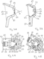
- Fig.2 shows the left temple holder 13 into which the left insertion wedge 45 of the chin guard 41 is inserted.
- Fig. 3A and 3B show the left bracket holder 13 in isolation.
- the bracket holder 13 has two insertion flanks 15 that protrude from a mounting plate 17 and run towards each other along the insertion direction E at an acute centering angle ⁇ .
- the centering angle ⁇ can be, for example, approximately 45 degrees.
- the insertion flanks 15 serve to center and align the chin guard 41 in the vertical direction during insertion and to form a stop for the chin guard 41 in the end position of the chin guard 41.
- the insertion flanks 15 are straight and open into a connecting section 19.
- a locking opening 21 is formed on each of the two insertion flanks 15 of the bracket holder 13.
- a support groove 23 is formed along the lower insertion flank 15 of the bracket holder 13.
- a magnetic element 25 is arranged on the connecting section 19 of the bracket holder 13.
- the bracket holder 13 also has a stabilization recess 27 which is offset vertically downwards with respect to the insertion flanks 15.
- the mounting plate 17 forms a common fastening unit in order to be able to integrate the insertion flanks 15 with the locking openings 21 and the support groove 23, the magnetic element 25 and the stabilizing recess 27 of the bracket mounting 13 into a helmet body of the helmet 11.
- the right bracket holder 13 is in relation to the Fig. 3A and 3B
- the left bracket holder 13 shown is mirror-imaged.
- Fig. 4A and 4B show the left insertion wedge 45 of the chin guard 41 in isolation.
- the insertion wedge 45 has an insertion section 47 with a trapezoidal outline.
- the insertion wedge 45 has a plate-shaped support 49 on which two contact flanks 51 are formed.
- the contact flanks 51 are designed to be complementary to the insertion flanks 15 of the respective bracket holder 13 of the helmet 11 such that the contact flanks 51 in the explained end position of the chin guard 41 bear positively against the insertion flanks 15 of the respective bracket holder 13.
- the plate-shaped support 49 of the insertion wedge 45 has two support webs 53, one of which is designed to engage in the support groove 23 of the respective bracket holder 13 of the helmet 11 in the explained end position of the chin guard 41.
- the helmet system shown has a locking device for locking the chin guard 41 in its end position on the helmet 11.
- the locking device comprises the locking openings 21 on the insertion flanks 15.
- the locking device comprises two movable latches 55, which are designed to engage in a locking position in one of the two locking openings 21 of the associated bracket holder 13.
- Each of the two latches 55 is attached to the carrier 49 via a spring arm 57.
- the two spring arms 57 are pressed apart by a spring 59 designed as a compression spring.
- the two latches 55 are in the direction of the Fig. 4A and 4B pre-tensioned in the locking position shown.
- the locking device further comprises a handle 61 in the form of a slider on the side of the respective end 43 of the chin guard 41, which is mounted on the carrier 49 so that it can move in a straight line.
- the handle 61 is connected to two control bars 63, each of which rests against one of the two spring arms 57 with a respective deflection slope 65.
- This forms a deflection device, whereby by manually moving the handle 61 away from the latches 55, the deflection bevels 65 deflect the spring arms 57 against the preload force of the spring 59.
- the latches 55 are released from the Fig. 4A and 4B shown locking position in the direction of an unlocking position in which the latches 55 no longer protrude from the contact flanks 51 of the insertion wedge 45.
- the carrier 49 with the two contact flanks 51 and the support webs 53, the two latches 55 and the handle 61 of the respective insertion wedge 45 form a locking assembly which can be designed identically for the two ends 43 of the chin guard 41 (left and right ends 43).
- the carrier 49 can be attached to the chin guard, for example, via attachment openings 67.
- a magnetic counter element 69 is also arranged on the insertion wedge 45.
- the magnetic element 25 of the respective bracket holder 13 of the helmet 11 and the magnetic counter element 69 of the associated end 43 of the chin guard 41 are designed to exert a magnetic attraction force on the chin guard 41 in the direction of its end position when the chin guard 41 is inserted into the bracket holders 13 in order to support the insertion movement and to fix the chin guard 41 in its end position.
- the magnetic elements 25 and magnetic counter elements 69 can also be arranged in positions other than in Fig. 3 and 4 shown, or additional magnetic elements and magnetic counter-elements may be provided.
- the chin guard 41 has a respective stabilizing elevation at its two ends 43, which in the explained end position of the chin guard 41 engages in a form-fitting manner in the stabilizing recess 27 of the associated bracket receptacle 13 in order to block the chin guard 41 against movements in directions perpendicular to the insertion direction E of the chin guard 41.
- the stabilizing elevation can in particular be provided on a recessed front side of the respective end 43 of the chin guard 41 (thus in the side view according to Fig.1 not apparent).
- Fig.5 illustrates an optional further development of the modular helmet system, in which the helmet system also has two ear protection modules 81.
- the two ear protection modules 81 can optionally be inserted instead of the chin guard 41 along the insertion direction E into the two bracket receptacles 13 of the helmet 11 in order to convert the helmet 11 into a so-called jet helmet configuration.
- Each of the two ear protection modules 81 can in turn have an insertion wedge, wherein the respective insertion wedge has two contact flanks that are designed to be complementary to the insertion flanks 15 of the respective bracket holder 13 of the helmet 11.
- the contact flanks of the ear protection modules 81 can rest in a form-fitting manner on the insertion flanks 15 of the respective bracket holder 13 in an end position of the respective ear protection module 81.
- each of the two ear protection modules 81 can have a magnetic counter element in order to - as explained in connection with the chin guard 41 - exert a magnetic attraction force on the ear protection module 81 in the direction of its end position when the respective ear protection module 81 is inserted.
- the two ear protection modules 81 do not have a mechanical locking device, in particular not the latch 55 and the handle 61. As a result, the ear protection modules 81 can be designed to be compact and lightweight.
- the explained helmet 11 has the advantage that the chin guard 41 can be attached in a simple manner, even while the user is wearing the helmet 11.
- the chin guard 41 only has to be inserted from the front in a substantially straight line into the bracket receptacles 13 of the helmet 11, whereby the insertion flanks 15 of the bracket receptacles 13 bring about the required centering without the need to actively perform additional pivoting movements.
- the chin guard 41 is arranged in a stable alignment on the helmet 11 and can also be supported in particular in a lateral direction.
- the locking device (latch 55, handle 61) is stable and easy to operate. The locking of the inserted chin guard 41 can take place automatically.
- the locking device is arranged almost completely on the chin guard 41, so that the helmet 41 is very light in the open face configuration. Since the respective locking unit at the two ends 43 of the chin guard 41 (support 49 with contact flanks 51 and support webs 53, latch 55, handle 61) can be designed identically, the helmet system can be manufactured cost-effectively. Through the combination of mechanical locking and magnetic fixation, the helmet system can easily be expanded to a 3-in-1 module system, which additionally provides a jet helmet configuration, with a compact and lightweight construction of the ear protection modules 81, which are only fixed magnetically.
Landscapes
- Physics & Mathematics (AREA)
- Acoustics & Sound (AREA)
- Helmets And Other Head Coverings (AREA)
Applications Claiming Priority (1)
| Application Number | Priority Date | Filing Date | Title |
|---|---|---|---|
| DE102022132430.3A DE102022132430A1 (de) | 2022-12-07 | 2022-12-07 | Modulares Helmsystem |
Publications (3)
| Publication Number | Publication Date |
|---|---|
| EP4381981A1 true EP4381981A1 (fr) | 2024-06-12 |
| EP4381981B1 EP4381981B1 (fr) | 2026-05-27 |
| EP4381981C0 EP4381981C0 (fr) | 2026-05-27 |
Family
ID=89076050
Family Applications (1)
| Application Number | Title | Priority Date | Filing Date |
|---|---|---|---|
| EP23213864.4A Active EP4381981B1 (fr) | 2022-12-07 | 2023-12-04 | Système de casque modulaire |
Country Status (5)
| Country | Link |
|---|---|
| US (1) | US12285070B2 (fr) |
| EP (1) | EP4381981B1 (fr) |
| AU (1) | AU2023270186A1 (fr) |
| DE (1) | DE102022132430A1 (fr) |
| ES (1) | ES3072996T3 (fr) |
Families Citing this family (1)
| Publication number | Priority date | Publication date | Assignee | Title |
|---|---|---|---|---|
| USD1121893S1 (en) * | 2022-08-03 | 2026-04-07 | Bell Sports, Inc. | Helmet |
Citations (4)
| Publication number | Priority date | Publication date | Assignee | Title |
|---|---|---|---|---|
| US5619755A (en) * | 1994-03-08 | 1997-04-15 | E.D.C. Sarl | Integral crash-helmet for motorcyclists and the like transformable into an open, jet-like helmet |
| ITMI20100510A1 (it) * | 2010-03-26 | 2011-09-27 | Locatelli S P A | Casco di sicurezza con mentoniera rimovibile |
| CN203262379U (zh) * | 2013-05-07 | 2013-11-06 | 厦门宇诠复材科技有限公司 | 安全帽可拆卸下颚结构 |
| IT201900001857A1 (it) * | 2019-02-08 | 2020-08-08 | Met S P A | Casco protettivo in particolare per uso sportivo. |
Family Cites Families (26)
| Publication number | Priority date | Publication date | Assignee | Title |
|---|---|---|---|---|
| DE3214020A1 (de) * | 1982-01-13 | 1983-07-21 | Uvex Winter Optik GmbH, 8510 Fürth | Schutzhelm |
| DE3233231A1 (de) * | 1982-09-07 | 1984-03-08 | Osthoff, Herbert, 8260 Mühldorf | Sturzhelm |
| DE19926419A1 (de) | 1999-06-10 | 2000-12-14 | Bayerische Motoren Werke Ag | Schutzhelm für Motorradfahrer |
| JP4596100B2 (ja) | 2000-09-28 | 2010-12-08 | 豊田合成株式会社 | 照明装置 |
| DE10240744B3 (de) * | 2002-09-02 | 2004-04-15 | Schuberth Werk Gmbh | Schutzhelm, insbesondere Rennfahrerhelm |
| FR2876005A1 (fr) * | 2004-04-29 | 2006-04-07 | Msa Gallet Sa | Perfectionnement pour casque de protection |
| JP2008070697A (ja) | 2006-09-15 | 2008-03-27 | Toyoda Gosei Co Ltd | 表示装置 |
| US20090044316A1 (en) * | 2007-08-14 | 2009-02-19 | Wilson Sporting Goods Co. | Sports helmet with removable facemask |
| CN201831006U (zh) | 2010-10-09 | 2011-05-18 | 岑杰强 | 一种易拆装的组合式头盔 |
| US20120284905A1 (en) | 2011-05-09 | 2012-11-15 | Hjc Corp. | Multi functional helmet |
| US20130025034A1 (en) * | 2011-07-28 | 2013-01-31 | Jacques Durocher | Ear protector for a hockey or lacrosse helmet |
| ITUD20120109A1 (it) | 2012-06-11 | 2013-12-12 | Bell Racing Europ S A | Casco provvisto di semi-mentoniera e relativo metodo di realizzazione |
| GB2518699B (en) | 2014-02-19 | 2015-08-05 | Racal Acoustics Ltd | Ballistic helmet |
| US10238165B2 (en) | 2014-03-07 | 2019-03-26 | Bell Sports, Inc. | Enduro mountain biking chin bar |
| DE102014109193A1 (de) * | 2014-07-01 | 2016-01-07 | Martin Schmitter | Konvertierbarer Integralhelm und Verfahren hierzu |
| DE102014218041A1 (de) * | 2014-09-10 | 2016-03-10 | Bayerische Motoren Werke Aktiengesellschaft | Schutzhelm, insbesondere Motorradhelm, mit schwenkbarem und abnehmbarem Kinnteil |
| US20170112227A1 (en) | 2015-10-23 | 2017-04-27 | Bell Sports, Inc. | Helmet having a chin bar collar |
| KR101795452B1 (ko) * | 2016-03-17 | 2017-11-10 | 주식회사 기도스포츠 | 타입 가변형 헬멧 |
| US11026467B2 (en) | 2016-05-05 | 2021-06-08 | Fox Head, Inc. | In-molded helmet chinbar |
| US10492559B1 (en) * | 2016-09-12 | 2019-12-03 | Bell Sports, Inc. | Helmet with removable chin bar |
| EP3758534A1 (fr) | 2018-03-02 | 2021-01-06 | 100% Speedlab, LLC | Systèmes et procédés de fixation de mentonnière |
| DE202019001181U1 (de) | 2019-03-11 | 2019-03-25 | Günter Krauter | Helm mit Kinnschutz |
| USD931546S1 (en) | 2020-03-24 | 2021-09-21 | Gunter Krauter | Helmet with chin protection |
| DE102020207719A1 (de) * | 2020-06-22 | 2021-12-23 | Uvex Sports Gmbh & Co. Kg | Helm |
| EP4013256B1 (fr) | 2020-11-05 | 2023-02-22 | Cardo Systems, Ltd. | Dispositif de fixation magnétique |
| CN113892719B (zh) * | 2021-11-15 | 2024-08-09 | 东莞市益安运动用品有限公司 | 一种带有分体式骨架结构的头盔 |
-
2022
- 2022-12-07 DE DE102022132430.3A patent/DE102022132430A1/de active Pending
-
2023
- 2023-11-20 AU AU2023270186A patent/AU2023270186A1/en active Pending
- 2023-11-28 US US18/520,622 patent/US12285070B2/en active Active
- 2023-12-04 ES ES23213864T patent/ES3072996T3/es active Active
- 2023-12-04 EP EP23213864.4A patent/EP4381981B1/fr active Active
Patent Citations (4)
| Publication number | Priority date | Publication date | Assignee | Title |
|---|---|---|---|---|
| US5619755A (en) * | 1994-03-08 | 1997-04-15 | E.D.C. Sarl | Integral crash-helmet for motorcyclists and the like transformable into an open, jet-like helmet |
| ITMI20100510A1 (it) * | 2010-03-26 | 2011-09-27 | Locatelli S P A | Casco di sicurezza con mentoniera rimovibile |
| CN203262379U (zh) * | 2013-05-07 | 2013-11-06 | 厦门宇诠复材科技有限公司 | 安全帽可拆卸下颚结构 |
| IT201900001857A1 (it) * | 2019-02-08 | 2020-08-08 | Met S P A | Casco protettivo in particolare per uso sportivo. |
Also Published As
| Publication number | Publication date |
|---|---|
| US12285070B2 (en) | 2025-04-29 |
| DE102022132430A1 (de) | 2024-06-13 |
| AU2023270186A1 (en) | 2024-06-27 |
| EP4381981B1 (fr) | 2026-05-27 |
| EP4381981C0 (fr) | 2026-05-27 |
| ES3072996T3 (en) | 2026-07-07 |
| US20240188669A1 (en) | 2024-06-13 |
Similar Documents
| Publication | Publication Date | Title |
|---|---|---|
| DE60130207T2 (de) | Schutzhelm mit Vorrichtung zum Verbinden von einem Träger | |
| DE69812594T2 (de) | Sturzhelm mit Vorrichtung zum Verriegeln und Entriegeln von beweglichen Teilen | |
| DE60214545T2 (de) | Vorrichtung zum Befestigen einer Visierscheibe an einem Helm | |
| DE69904687T2 (de) | Sicherheitshelm und Befestigungsvorrichtung für Beatmungsmaske | |
| DE69321234T2 (de) | Hochkippbare befestigung für ein nachtsichtsystem | |
| DE69025610T2 (de) | Helm | |
| DE69813664T2 (de) | Helm | |
| EP3435804A1 (fr) | Ensemble visière | |
| EP3493697A1 (fr) | Casque de protection | |
| EP3900564B1 (fr) | Bouclier mobile | |
| EP4027824B1 (fr) | Mécanisme de visière pour casque de protection | |
| DE3145664A1 (de) | "schutzhelm fuer den kopf mit verriegelungsmitteln" | |
| DE69911693T2 (de) | Helm | |
| DE102020002614A1 (de) | Schutzhelm mit mechanischen Codierungen für Steckverbindungen zwischen lnnenausstattung und Tragstruktur | |
| DE102021110197A1 (de) | Schutzhelm mit einem Zwischenstück zur Veränderung des Schwerpunkts und Anordnungen umfassend einen solchen Schutzhelm und zwei alternative Zwischenstücke | |
| DE602004007383T2 (de) | Befestigungsvorrichtung einer abnehmbaren lampe an einem schutzhelm | |
| DE102022132430A1 (de) | Modulares Helmsystem | |
| DE60214306T2 (de) | Schwimmbrille | |
| EP3928651A1 (fr) | Casque | |
| EP3708016A1 (fr) | Casque avec protection du menton | |
| DE202011109220U1 (de) | Oberkörperprotektor für Nackenprotektoren | |
| DE102013019775B4 (de) | Schutzhelmsystem | |
| DE102019101412B4 (de) | Schutzhelm mit Verstellmechanismus | |
| EP3384795B1 (fr) | Support pour verres de lunettes et casque pourvu d'un tel support | |
| DE10050310C1 (de) | Sturzhelm |
Legal Events
| Date | Code | Title | Description |
|---|---|---|---|
| PUAI | Public reference made under article 153(3) epc to a published international application that has entered the european phase |
Free format text: ORIGINAL CODE: 0009012 |
|
| STAA | Information on the status of an ep patent application or granted ep patent |
Free format text: STATUS: THE APPLICATION HAS BEEN PUBLISHED |
|
| AK | Designated contracting states |
Kind code of ref document: A1 Designated state(s): AL AT BE BG CH CY CZ DE DK EE ES FI FR GB GR HR HU IE IS IT LI LT LU LV MC ME MK MT NL NO PL PT RO RS SE SI SK SM TR |
|
| STAA | Information on the status of an ep patent application or granted ep patent |
Free format text: STATUS: REQUEST FOR EXAMINATION WAS MADE |
|
| 17P | Request for examination filed |
Effective date: 20241212 |
|
| GRAP | Despatch of communication of intention to grant a patent |
Free format text: ORIGINAL CODE: EPIDOSNIGR1 |
|
| STAA | Information on the status of an ep patent application or granted ep patent |
Free format text: STATUS: GRANT OF PATENT IS INTENDED |
|
| INTG | Intention to grant announced |
Effective date: 20260213 |
|
| GRAS | Grant fee paid |
Free format text: ORIGINAL CODE: EPIDOSNIGR3 |
|
| GRAA | (expected) grant |
Free format text: ORIGINAL CODE: 0009210 |
|
| STAA | Information on the status of an ep patent application or granted ep patent |
Free format text: STATUS: THE PATENT HAS BEEN GRANTED |
|
| AK | Designated contracting states |
Kind code of ref document: B1 Designated state(s): AL AT BE BG CH CY CZ DE DK EE ES FI FR GB GR HR HU IE IS IT LI LT LU LV MC ME MK MT NL NO PL PT RO RS SE SI SK SM TR |
|
| REG | Reference to a national code |
Ref country code: CH Ref legal event code: F10 Free format text: ST27 STATUS EVENT CODE: U-0-0-F10-F00 (AS PROVIDED BY THE NATIONAL OFFICE) Effective date: 20260527 Ref country code: GB Ref legal event code: FG4D Free format text: NOT ENGLISH |
|
| REG | Reference to a national code |
Ref country code: CH Ref legal event code: R17 Free format text: ST27 STATUS EVENT CODE: U-0-0-R10-R17 (AS PROVIDED BY THE NATIONAL OFFICE) Effective date: 20260601 |
|
| U01 | Request for unitary effect filed |
Effective date: 20260527 |
|
| U07 | Unitary effect registered |
Designated state(s): AT BE BG DE DK EE FI FR IT LT LU LV MT NL PT RO SE SI Effective date: 20260602 |
|
| REG | Reference to a national code |
Ref country code: ES Ref legal event code: FG2A Ref document number: 3072996 Country of ref document: ES Kind code of ref document: T3 Effective date: 20260707 |