EP4382012A1 - Dispositif de fixation pour une garniture de siège ou de couvercle sur un objet sanitaire ainsi qu'installation sanitaire comprenant un objet sanitaire et une garniture de siège ou de couvercle - Google Patents
Dispositif de fixation pour une garniture de siège ou de couvercle sur un objet sanitaire ainsi qu'installation sanitaire comprenant un objet sanitaire et une garniture de siège ou de couvercle Download PDFInfo
- Publication number
- EP4382012A1 EP4382012A1 EP23210350.7A EP23210350A EP4382012A1 EP 4382012 A1 EP4382012 A1 EP 4382012A1 EP 23210350 A EP23210350 A EP 23210350A EP 4382012 A1 EP4382012 A1 EP 4382012A1
- Authority
- EP
- European Patent Office
- Prior art keywords
- threaded rod
- abutment element
- fastening device
- seat
- sanitary
- Prior art date
- Legal status (The legal status is an assumption and is not a legal conclusion. Google has not performed a legal analysis and makes no representation as to the accuracy of the status listed.)
- Pending
Links
Images



Classifications
-
- A—HUMAN NECESSITIES
- A47—FURNITURE; DOMESTIC ARTICLES OR APPLIANCES; COFFEE MILLS; SPICE MILLS; SUCTION CLEANERS IN GENERAL
- A47K—SANITARY EQUIPMENT; ACCESSORIES THEREFOR, e.g. TOILET ACCESSORIES
- A47K13/00—Seats or covers for all kinds of closets
- A47K13/24—Parts or details not covered in, or of interest apart from, groups A47K13/02 - A47K13/22
- A47K13/26—Mounting devices for seats or covers
-
- A—HUMAN NECESSITIES
- A47—FURNITURE; DOMESTIC ARTICLES OR APPLIANCES; COFFEE MILLS; SPICE MILLS; SUCTION CLEANERS IN GENERAL
- A47K—SANITARY EQUIPMENT; ACCESSORIES THEREFOR, e.g. TOILET ACCESSORIES
- A47K13/00—Seats or covers for all kinds of closets
-
- A—HUMAN NECESSITIES
- A47—FURNITURE; DOMESTIC ARTICLES OR APPLIANCES; COFFEE MILLS; SPICE MILLS; SUCTION CLEANERS IN GENERAL
- A47K—SANITARY EQUIPMENT; ACCESSORIES THEREFOR, e.g. TOILET ACCESSORIES
- A47K13/00—Seats or covers for all kinds of closets
- A47K13/24—Parts or details not covered in, or of interest apart from, groups A47K13/02 - A47K13/22
- A47K13/247—Covers with sliding wings or wings pivoting around a vertical axis
Definitions
- the invention relates to a fastening device for a seat or lid fitting on a sanitary object.
- a seat or lid assembly is usually attached to a sanitary object in the form of a toilet, urinal or bidet, whereby the seat or lid assembly usually has a seat, possibly also a lid, or only a lid.
- the seat or lid assembly is usually attached to a rear top side of the sanitary object, i.e. close to the wall in the assembly position, using suitable fastening devices.
- a fastening device usually comprises a fastening rod which is inserted through an opening provided in the sanitary object.
- the fastening rod is provided with an external thread so that a retaining nut can be screwed on from the inside of the sanitary object, i.e. onto the rod section which is inserted through.
- the fastening rod either rests with a corresponding, disc-shaped collar or is supported by a screwed-on abutment disc or similar, so that the sanitary object is braced accordingly and the fastening rod is fixed.
- the sanitary item has two corresponding openings so that two such fastening rods can be mounted.
- the seat or cover fitting is then attached to the rod ends that protrude upwards on the top of the sanitary object.
- the seat or cover fitting is provided with corresponding hinges with fastening sections that have through or blind holes with which they are inserted onto the rod ends, whereby a corresponding locking or clamping mount is achieved.
- Such hinges can be formed, for example, by means of two fluid rotary dampers, which have two sections that can be rotated relative to one another and dampened by a fluid, whereby one section is firmly connected to the seating arrangement, while the other section has the through-hole or blind hole and is placed on the rod end.
- the fastening devices i.e. the fastening rods, as well as the seat or lid fitting are only installed on site when the toilet, urinal or bidet is installed by the customer.
- the two fastening devices are first attached to the sanitary object, after which the sanitary object is mounted on the wall. Only then is the seat or lid fitting attached to the fastening devices.
- the problem here is that the fitter has to position and align the fastening devices on site, since the openings provided on the ceramic side usually have a relatively large diameter, for example in the range of 1 - 2 cm, which means that the position of the fastening devices or the fastening rods is ultimately variable.
- the fitter is then forced to design the distance between the two fastening rods exactly so that it corresponds to the distance between the fastening elements provided on the seat fitting or the through or blind holes, so that these can be attached without any problems.
- the alignment of the fastening devices must be precise on both sides and to the front and back so that the seat set that is subsequently installed also sits exactly symmetrically on the sanitary object. This is sometimes associated with considerable effort and not infrequently with the result that the seat or cover set is not exactly symmetrical. It is possible to mount the fastening devices on the sanitary object at the factory so that they are correctly positioned and aligned. In this case, however, the fastening rods protrude from the ceramic top, the protruding rod length is approx.
- the invention is therefore based on the problem of providing an improved fastening device.
- a fastening device for a seat or cover fitting on a sanitary object comprising a threaded rod which, in the assembly position, passes through an opening in the sanitary object and has an external thread section and an internal thread bore, a first and a second abutment element which, in the assembly position, receive a section of the sanitary object between them and are braced against it, at least one nut to be screwed onto the external thread section for bracing the abutment elements and the threaded rod, and a retaining pin which receives the seat fitting and has an external thread section which can be screwed into the internal thread bore.
- the fastening device according to the invention is characterized in that, unlike in the prior art, no one-piece fastening rod is provided, but a quasi two-piece fastening rod. This is formed on the one hand from the threaded rod and on the other hand from the retaining pin that can be screwed to it.
- the threaded rod is first pushed through a corresponding opening in the sanitary object and a first abutment element is positioned on the inside of the sanitary object and a second abutment element on the outside, after which a nut is screwed onto an external thread section of the threaded rod, which is accessible from the inside of the ceramic, by means of which the ceramic section located between the abutment elements is clamped between the abutment elements.
- the threaded rod lies almost flush with the abutment element, which in turn is positioned on rests on the ceramic top and ultimately only protrudes slightly. In any case, the threaded rod mounted in this way does not protrude significantly from the ceramic top.
- the retaining pin Only when the seat or cover fitting is actually to be mounted is the retaining pin with its external thread screwed into the internal threaded hole of the threaded rod, which is accessible from the ceramic top, so that the fastening rod is ultimately completed and the retaining pin creates a fastening section protruding from the top, onto which the fastening element on the fitting side can then be placed.
- This multi-part design of the fastening device offers the advantage of pre-assembling the main fitting elements at the factory without causing the problems described above with regard to special packaging or possible handling and injury problems. This is because it is possible to assemble the threaded rod and the two abutment elements at the factory without any problems and to align them precisely so that, when assembled, the threaded rods and with them the internal threaded holes are optimally positioned.
- the sanitary object pre-equipped in this way can then be easily packaged and handled accordingly during assembly until the toilet, urinal or bidet is mounted on the wall, as the pre-assembled fastening device parts do not protrude or build up in relation to the ceramic top.
- the threaded rod can have a support section with which it can be held against the second abutment element can be tensioned.
- the threaded rod is supported and supported on this side on the second abutment element via this support section.
- the second abutment element is therefore a separate component.
- the second abutment element can be formed in one piece with the threaded rod.
- the threaded rod therefore has a terminal collar which projects radially and which, forming the second abutment element, is supported on the top of the sanitary object in the assembly position.
- the first abutment element, or the first and second abutment elements are preferably designed either as a disc or as a plate. Their diameter or width or length are dimensioned accordingly to ensure that, regardless of the final position in which the threaded rod is arranged, there is always sufficient support on the sanitary object.
- the first and/or the second abutment element can also be held captive on the threaded rod. This enables simple assembly, since the respective captive abutment element does not have to be handled and positioned separately.
- the second abutment element in particular is expediently held captive, which can be done, for example, by wobbling or gluing.
- the second abutment element is formed in one piece with the threaded rod, i.e. designed as a protruding collar, so that in this case no separate abutment element would have to be secured.
- the first abutment element is always a separate component. This can be designed as a separate disc or plate as described and, during assembly, when the threaded rod is inserted through the opening, can also be pushed onto the threaded rod from the inside of the ceramic and fixed with the nut.
- a practical alternative invention provides for the first abutment element to have a longitudinal slot through which the threaded rod passes, so that the abutment element can be tilted towards the threaded rod.
- This design as a type of tilting dowel makes it possible to Before fitting the threaded rod, slide the abutment element onto it and secure it with the nut. For assembly, the first abutment element must be brought into an assembly position in which it is tilted towards the threaded rod.
- the arrangement of the threaded rod and the first abutment element has a narrow shape and can be guided through the opening.
- the first abutment element then automatically tilts out again, protrudes from the threaded rod on both sides and grips behind the sanitary object so that it is clamped against the nut when the nut is tightened.
- the tilting option is achieved by creating the corresponding longitudinal slot.
- a support section is provided on the threaded rod, i.e. a separate second abutment element is used, this support section is expediently implemented by means of a shoulder provided on the end of the threaded rod, with which the threaded rod rests against the second abutment element.
- This shoulder can be made relatively thin, since it only serves as support, but does not bear any other load during operation.
- the second abutment element particularly preferably has a recess for countersunk accommodation of the shoulder. This can ensure that when the shoulder is arranged at the end of the threaded rod and countersunk accommodation, the threaded rod ultimately ends flush with the second abutment element, i.e. the disk or plate, and therefore does not protrude at all above the abutment plane.
- the shoulder can, for example, be conical, while the recess has a shape-compatible countersink.
- the fastening device is countered by the nut screwed onto the threaded section on the bottom or inside.
- the threaded rod has a receptacle for attaching a tool, via which receptacle it is possible to use one tool to grip the nut on the one hand and another tool to grip the threaded rod on the other, in order to either only to hold the nut while the nut is being screwed on, or to hold the nut and actively screw the threaded rod, or to screw both together accordingly.
- the holder can be designed as a slot on the front side of the threaded rod into which a screwdriver can be inserted.
- the holder can also be designed as a polygonal recess extending into the internal threaded hole, for example as a hexagon socket to accommodate an Allen key.
- the second abutment element is arranged on the surface of the sanitary object, which is usually covered with a glaze.
- the second abutment element can have a contact section made of a softer material such as a plastic material that rests on the sanitary object.
- the second abutment element can therefore be provided with a plastic coating on one side, which is sprayed on or glued on, for example. This plastic section, which is significantly softer than the metal from which the second abutment element is made, effectively prevents direct metal-glaze contact, and scratches are avoided.
- the second abutment element can also be supported against the sanitary object via a contact disk, e.g. made of a plastic material. This means that the soft contact disk sits first on the glaze surface, followed by the second abutment element. Here, too, direct glaze-metal contact is avoided.
- the respective retaining pin with its external thread is only screwed into the internal threaded hole during the final assembly of the seating set.
- the retaining pin expediently has a receptacle for attaching a tool.
- a receptacle can, for example, be a slot provided on the front side of the retaining pin into which a screwdriver can be inserted.
- the retaining pin has a polygonal pin section that can be gripped with an open-end wrench.
- the retaining pin itself advantageously has one or more clamping or locking elements for a clamping or locking holder of the seating set.
- a clamping or locking element can, for example, be a clamping ring made of plastic or metal that snaps into a groove on the retaining pin side and has a slightly larger outer diameter than the through hole or blind hole on the fastening element of the seating set.
- a cover can be provided which, in the assembled position, is placed on the second abutment element, covering it, and through which the retaining pin extends. If the second abutment element is designed as a round disk or round collar, this cover, which is also correspondingly round, therefore covers the second abutment element. It is conceivable that the cover also has a corresponding sleeve-like section into which the retaining pin engages in sections, so that the retaining pin is also virtually hidden as long as it does not engage in the fastening device of the seating arrangement.
- the fastening device of the seating arrangement can also be supported on the cover, for which purpose the cover can be rounded at the upper end, for example, if the attached section of the fastening device on the seating arrangement has a cylindrical outer shape, so that a positive fit is created.
- the invention also relates to a sanitary arrangement comprising a sanitary object and a seat set, which is fastened to the sanitary object by means of two fastening devices of the type described above.
- the sanitary object for example a toilet, urinal or bidet, has two corresponding, mostly circular openings in the rear area of the ceramic top, in which the Fastening devices can be mounted.
- the two openings are completely covered by the second abutment elements in the assembly position; alternatively, this complete covering can also be achieved by means of the cover provided if necessary. In any case, the openings are no longer visible in the final assembly position.
- the seat or lid fitting can be just a swivel seat or lid, as is the case with a bidet or urinal, for example.
- it can be a seat and lid combination, as is particularly useful with a toilet.
- Two rotary dampers can also be attached to the seat or cover fitting, each of which has a connecting section with a retaining pin holder into which the respective retaining pin engages.
- the retaining pin holder usually implemented in the form of a through hole or blind hole, allows the rotary damper, which is usually designed as a fluid damper, to be easily attached to the respective retaining pin.
- the rotary damper usually a cylindrical component, is accommodated in a corresponding, shape-compatible holder of the seat or cover fitting with a holding section, relative to which holding section the connecting section can be rotated in a damped manner. In the assembly position, the axis of rotation runs horizontally and perpendicular to the longitudinal axis of the retaining pin.
- the respective connecting sections are suitably cylindrical and can be accommodated in a form-compatible receptacle of the cover. This enables the cover, which may be slightly twisted after being attached, to automatically align itself precisely due to the form fit, as it is carried along by the engaging connecting section.
- Fig.1 shows an exploded view of a fastening device 1 according to the invention and a sanitary object 2, for example a toilet, which is only indicated.
- the fastening device 1 comprises a threaded rod 3 with an external thread section 4 extending over approximately half of its length and an internal threaded bore 5 axially introduced on one end face.
- a first abutment element 6 is provided here in the form of a slightly curved plate, which abutment element 6 has an opening 7 so that it can be pushed onto the threaded rod 3.
- the fastening device 1 which is to be arranged on the other side of the sanitary object 2, comprises at least one second abutment element 11, here in the form of a circular disk with a preferably conically countersunk opening 12.
- the threaded rod 3 is guided through the opening, which will be discussed below, whereby the threaded rod 3 with a support section 13 provided at its upper end, which is designed as a radially protruding shoulder and in the example shown is truncated cone-shaped, and which rests flush on the second abutment element 11 or in the opening 12.
- a retaining pin 14 with an externally threaded section 15, which is to be screwed into the internally threaded bore 5.
- the internally threaded bore 5 is accessible from the top 16 of the sanitary object 2, since, as described, the threaded rod 3 is supported with the support section on the abutment element 11.
- the retaining pin 14 has a receptacle 17 for a tool, for example an open-end wrench, so that it can be tightened accordingly. Instead of this square receptacle 17, a slot for a tool receptacle can also be provided on the front side of the retaining pin 14.
- the second abutment element 11 can also be made in one piece with the threaded rod 3, so that in this case a common component is formed, in which case a support section 13 is not required.
- the sanitary object 2 itself has a round opening 18 through which the threaded rod 3 is guided for assembly as described. In the final assembly position, the opening 18 is completely covered by the second abutment element 11 and is therefore not visible. Of course, two such openings are provided on the sanitary object, each for a fastening device 1, in order to fix the seat or cover fitting.
- the threaded rod 3 is first pushed through the opening 12 of the second abutment element 11, after which the threaded rod 3 is inserted through the opening 18 so that the abutment element 11 rests on the top 16 of the sanitary object 2.
- a plastic coating can be applied to the underside of the abutment element 11, which has a somewhat dampening effect because it is soft, so that scratching of the top 16, which is usually covered with a glaze, is avoided.
- a plastic contact disc 31 can also be used as Scratch protection can be arranged between the abutment element 11 and the glaze surface.
- the first abutment element 6 is placed on the threaded rod 3 from the underside, followed by the washer 8, after which the self-locking nut 9 is finally screwed on.
- the nut 9 is tightened so that the sanitary object 2 is firmly clamped between the two abutments 6, 11.
- the clamping is possible because, as described, the threaded rod 3 is supported on the second abutment element 11 via the support section 13. Due to the slightly curved design of the first abutment element 6, it is pressed slightly flat when the nut 9 is tightened so that it is axially clamped, which, in addition to the self-locking function of the nut 9, ensures that the screw connection does not come loose.
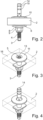
- FIG.3 shows a view of the sanitary object 2 from above.
- the second abutment element 11 is clearly resting on the top side 16, the opening is completely covered. It is also shown that the truncated cone-shaped support section 13 is recessed into the opening 12, which is also conical, so that the support section 13 is virtually flush with the top side of the support element 11.
- This assembly situation corresponds to the factory assembly situation, i.e. that all elements of the fastening devices are pre-assembled on the sanitary object 2, which of course usually has two openings 18 so that a toilet seat set is fixed by means of two fastening devices 1, except for the retaining pin 14.
- the threaded rod 3 can be positioned exactly within the opening 18, which is significantly larger in diameter, so that the two threaded rods 3 of the two fastening devices 1 can be optimally aligned and positioned at the factory, for example using an assembly template or an assembly frame.
- the threaded rods 3 can be precisely aligned to the front and back as well as to both sides, so that it is ensured that the seat or cover fitting is then precisely aligned with respect to the sanitary object 2.
- Fig.3 the factory assembly situation of the central parts of the fastening devices 1.
- the sanitary object 2 is then packed and transported and also removed and installed by the fitter on site. Only when the sanitary object 2, i.e. the toilet, is attached to the wall, for example, the final assembly of the seat or lid fitting takes place. To do this, it is only necessary to insert the two retaining pins 14 into the internal threaded hole 5, which, see Fig.3 , is freely accessible, and tightened using a suitable tool.
- the threaded rod 3 is precisely aligned and positioned, this also necessarily applies to the screwed-in retaining pins 14, so that the fitter then only has to place the seat or cover fitting onto the retaining pins 14; any additional alignment work is not required.
- the seat or cover fitting is, for example, locked onto the retaining pins, for which purpose locking grooves 19 are provided on the pin side, into which the corresponding locking elements of the fastening elements of the seat or cover fitting snap.
- Fig.4 shows the final assembly position, i.e. when the sanitary object 2 is mounted on the wall, for example.
- the retaining pin 14 is clearly screwed into the internal threaded hole and tightened; it protrudes from the sanitary object 2 accordingly.
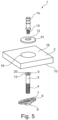
- Fig.5 shows a further embodiment of a fastening device 1 according to the invention, wherein the same reference numerals are used for the same components.
- a threaded rod 3 with an external thread section 4 and an internal threaded bore 5 is provided.
- a first abutment element 6 is shown here in an elongated form, it has a longitudinal slot-like opening 7, which is significantly longer than in the embodiment according to Fig.1 This elongated, slot-like opening allows it is that the plate-like first abutment element functions as a kind of tilting dowel, which will be discussed below.
- a nut 9 is also provided, which here is designed as a square nut, for example.
- a second abutment element 11 with an opening 12, which in turn is conically countersunk, corresponding to the truncated cone-like geometry of the support section 13 of the threaded rod 3.
- the retaining pin 14 which is screwed with its external thread section 15 into the internal threaded bore 5.
- the internal threaded hole 5 is provided with a receptacle 20 in the form of a hexagon socket for a tool such as an Allen key.
- This receptacle 20 makes it possible to attach a tool and either actively rotate and screw the threaded rod 3 when clamping the components against the sanitary object 2, or to hold and lock the threaded rod accordingly when screwing the nut 9.
- the threaded rod 3 is first inserted through the opening 12 of the second abutment element.
- the first abutment element is then inserted onto the threaded rod 3 and the nut 9 is screwed a short distance onto the threaded section 4.
- the first abutment element 6 can now be tilted towards the threaded rod 3 due to the length of the slot-like opening 7, i.e. the abutment element 6 does not protrude orthogonally to the side, but runs relatively close or tilted to the threaded rod 3. This enables this pre-assembled configuration to be guided through the opening 18 of the sanitary object 2.
- the tightening begins. This can be done as follows: described by inserting a tool into the receptacle 20 and turning the threaded rod 3, whereby the nut 9 is held and locked with a second tool. It is of course also conceivable that only the nut 9 is turned, while the threaded rod 3 is locked in the receptacle 20 using the tool.
- the first abutment element 6 is clamped against the underside 10 and the second abutment element 11 against the top 16 of the sanitary object, by which the threaded rod 3 is fixed.
- Fig.7 shows, which according to the arrangement Fig.3
- the flush mounting of the support section 13 on the disk-shaped second abutment element 11 can be clearly seen, as well as the fact that on the one hand the mounting 20 is exposed, but on the other hand of course also the internal threaded bore 5.
- Fig.8 shows an embodiment of a fastening device 1 according to the invention, which is identical to that of Fig.5 corresponds, which is why reference is made to the relevant description.
- the only difference here is the design of the receptacle 20, which enables a tool to be used on the threaded rod 3.
- the receptacle 20 is designed here as a slot that extends transversely on the front side of the support section 13 and allows a screwdriver to be inserted there.
- the first abutment element 6 in the form of the elongated plate-like component with the elongated slot 7 is provided for realizing a tilt dowel-like design, as are the nut 9 and the second abutment element 11 with its opening 12 and the retaining pin 14.
- the assembly process is carried out as for the previous embodiment according to Fig.5 described. Only for screwing or locking the threaded rod 3, another tool is to be used here, namely a screwdriver, which is inserted into the slot-like receptacle 20.
- FIG.9 The factory pre-assembly situation is in Fig.9 shown.
- the support section 13 is shown flush with the top of the second abutment element 11, which in turn completely covers the opening 18 in the sanitary object, due to the recess in the opening 12.
- Also visible is the accessibility of the slot-like receptacle 20, which is open at the top, and the internal threaded hole 5. As described, it is now only necessary to screw in the retaining pin 14.
- FIGS. 10 - 13 show a partial view of a sanitary arrangement 21, with a sanitary object 2 shown in a partial view, here in the form of a toilet.
- a toilet which is usually made of ceramic
- two openings 18 are provided, in which the fastening devices 1, apart from the two retaining pins 14, are already mounted.
- a plastic protective layer is applied to the underside of the abutment elements 11 to prevent scratching of the glaze coating, alternatively a thin plastic disk can also be arranged between them.
- Fig.10 the factory pre-assembly final position already shown for the above design variants.
- the threaded rods 3 and with them the threaded holes 5 are optimally positioned and aligned within the significantly larger openings 18, both to each other and to the front and back as well as to both sides of the sanitary object 2.
- the sanitary object is packaged in this factory pre-assembly form, which is also possible using packaging materials that have been used previously, since the retaining pins 14, which would otherwise protrude disadvantageously if already screwed in, are not yet screwed in. It is just as simple and problem-free handling after unpacking, since the retaining pins do not hinder the subsequent handling and assembly process.
- Fig. 11 shows the sanitary object 2 and a combined seat-cover assembly 22 to be attached to it, comprising a seat 23 shown here in detail and a cover 24, both of which can be pivoted relative to one another, for which purpose two corresponding rotary dampers 25 are provided on the assembly 22 in a manner known per se.
- Each rotary damper has a connecting section 26 with a blind hole 27 into which the retaining pins 14 are inserted and locked.
- Fig. 11 Shown in Fig. 11 the two retaining pins 14 that have not yet been screwed in, as well as two plastic covers 28. These serve to cover the second abutment elements 11, i.e. to hide them, as well as the retaining pin 14 when screwed in, so that this too is not visible.
- Fig. 12 shows the arrangement Fig. 11 , whereby the two retaining pins 14 are screwed into the internal threaded holes 5 and protrude from the sanitary object 2.
- the covers 28 are then, see Fig. 13 , pushed over the retaining pins 14 so that on the one hand they cover the abutment elements 11, but on the other hand also partially cover the respective retaining pin 14, for which purpose each cover 28 has a cylindrical section 29 which partially surrounds the retaining pin 14.
- This section 29 is provided on its upper side with a rounded receptacle 30 which corresponds to the cylindrical shape of the respective connecting section 26 of the rotary dampers 25.
- the seat-cover assembly 22 For the final assembly of the seat-cover assembly 22, it is now placed with the two blind holes 27 on the two retaining pins 14 and locked into place, whereby in the final locking position the cylindrical connecting sections 26 are accommodated in the rounded receptacles 30. If one of the covers 28 is slightly twisted about the axis of the retaining pin, this slight twist is corrected accordingly by the positive engagement of the cylindrical connecting sections 26 in the receptacles 30 and the cover 28 is aligned.
- the covers 28 are simple plastic parts, while the other components of the fastening device 1 are metal components.
Landscapes
- Health & Medical Sciences (AREA)
- Public Health (AREA)
- Toilet Supplies (AREA)
- Sanitary Device For Flush Toilet (AREA)
- Supports Or Holders For Household Use (AREA)
Applications Claiming Priority (1)
| Application Number | Priority Date | Filing Date | Title |
|---|---|---|---|
| DE102022132678.0A DE102022132678A1 (de) | 2022-12-08 | 2022-12-08 | Befestigungseinrichtung für eine Sitz- oder Deckelgarnitur an einem Sanitärgegenstand sowie Sanitäranordnung umfassend einen Sanitärgegenstand und eine Sitz- oder Deckelgarnitur |
Publications (1)
| Publication Number | Publication Date |
|---|---|
| EP4382012A1 true EP4382012A1 (fr) | 2024-06-12 |
Family
ID=88837455
Family Applications (1)
| Application Number | Title | Priority Date | Filing Date |
|---|---|---|---|
| EP23210350.7A Pending EP4382012A1 (fr) | 2022-12-08 | 2023-11-16 | Dispositif de fixation pour une garniture de siège ou de couvercle sur un objet sanitaire ainsi qu'installation sanitaire comprenant un objet sanitaire et une garniture de siège ou de couvercle |
Country Status (5)
| Country | Link |
|---|---|
| US (1) | US20240188774A1 (fr) |
| EP (1) | EP4382012A1 (fr) |
| CN (1) | CN118161082A (fr) |
| CA (1) | CA3222481A1 (fr) |
| DE (1) | DE102022132678A1 (fr) |
Families Citing this family (1)
| Publication number | Priority date | Publication date | Assignee | Title |
|---|---|---|---|---|
| DE102024119800A1 (de) * | 2024-07-11 | 2026-01-15 | Hamberger Industriewerke Gmbh | Befestigungsstift; Bausatz für WCs |
Citations (4)
| Publication number | Priority date | Publication date | Assignee | Title |
|---|---|---|---|---|
| CH375861A (de) * | 1959-12-16 | 1964-03-15 | Gebert & Cie | Vorrichtung an einer Klosettschüssel zur Befestigung eines Sitzringes oder Klosettdeckels |
| DE202004010520U1 (de) * | 2004-07-06 | 2004-09-09 | Pagette Sanitär Produktions- und Vertriebsgesellschaft mbH | Bügelanordnung |
| WO2016070707A1 (fr) * | 2014-11-04 | 2016-05-12 | 厦门豪帝卫浴工业有限公司 | Siège de support à insertion en sens descendant pour couvercle de chaise percée ultra-mince |
| EP3797661B1 (fr) * | 2019-05-24 | 2021-12-15 | Geberit International AG | Cheville à bascule |
Family Cites Families (9)
| Publication number | Priority date | Publication date | Assignee | Title |
|---|---|---|---|---|
| GB2309040B (en) * | 1996-01-09 | 1998-06-10 | Lu Pien Rueng | Device for adjustably positioning a cover on a toilet |
| ITPD20070401A1 (it) * | 2007-12-04 | 2009-06-05 | Fischer Italia S R L Uniperson | Dispositivo di fissaggio, particolarmente per sanitari sospesi a parete |
| US8656522B2 (en) * | 2008-11-26 | 2014-02-25 | Michael R. Leibfried | Toilet and toilet seat mounting system |
| CN203252575U (zh) | 2013-05-14 | 2013-10-30 | 许肖峰 | 一种快速拆装的座便器盖板支座 |
| CN104305929A (zh) * | 2014-06-26 | 2015-01-28 | 福建拓宇卫浴有限公司 | 一种马桶盖固定装置 |
| DE102014119493B4 (de) * | 2014-12-23 | 2025-07-31 | Duravit Aktiengesellschaft | Wc |
| EP3742009B1 (fr) | 2019-05-24 | 2023-05-10 | Geberit International AG | Dispositif de fixation pour recouvrements de toilettes |
| DE102019132130A1 (de) * | 2019-11-27 | 2021-05-27 | Duravit Aktiengesellschaft | Gelenkanordnung zur schwenkbaren Lagerung eines Deckels, eines Sitzes oder einer Sitz-Deckel-Garnitur an einem keramischen Sanitärgegenstand |
| MX2021001913A (es) * | 2020-02-18 | 2021-08-19 | Bemis Mfg Co | Conjunto de fijacion para bisagra de asiento de inodoro. |
-
2022
- 2022-12-08 DE DE102022132678.0A patent/DE102022132678A1/de active Pending
-
2023
- 2023-11-16 EP EP23210350.7A patent/EP4382012A1/fr active Pending
- 2023-11-29 US US18/522,623 patent/US20240188774A1/en active Pending
- 2023-12-05 CN CN202311655234.5A patent/CN118161082A/zh active Pending
- 2023-12-08 CA CA3222481A patent/CA3222481A1/fr active Pending
Patent Citations (4)
| Publication number | Priority date | Publication date | Assignee | Title |
|---|---|---|---|---|
| CH375861A (de) * | 1959-12-16 | 1964-03-15 | Gebert & Cie | Vorrichtung an einer Klosettschüssel zur Befestigung eines Sitzringes oder Klosettdeckels |
| DE202004010520U1 (de) * | 2004-07-06 | 2004-09-09 | Pagette Sanitär Produktions- und Vertriebsgesellschaft mbH | Bügelanordnung |
| WO2016070707A1 (fr) * | 2014-11-04 | 2016-05-12 | 厦门豪帝卫浴工业有限公司 | Siège de support à insertion en sens descendant pour couvercle de chaise percée ultra-mince |
| EP3797661B1 (fr) * | 2019-05-24 | 2021-12-15 | Geberit International AG | Cheville à bascule |
Also Published As
| Publication number | Publication date |
|---|---|
| DE102022132678A1 (de) | 2024-06-13 |
| CN118161082A (zh) | 2024-06-11 |
| CA3222481A1 (fr) | 2024-06-08 |
| US20240188774A1 (en) | 2024-06-13 |
Similar Documents
| Publication | Publication Date | Title |
|---|---|---|
| EP0458069B1 (fr) | Liaison transversale pour des barres profilées | |
| EP3827723B1 (fr) | Agencement articulaire destiné à l' assemblage pivotant d'un couvercle, d'un siège ou d'une garniture de couvercle de siège sur une cuvette sanitaire en céramique | |
| DE102012103721A1 (de) | Befestigungsvorrichtung für Sanitärkeramiken und Befestigungsanordnung | |
| EP4382012A1 (fr) | Dispositif de fixation pour une garniture de siège ou de couvercle sur un objet sanitaire ainsi qu'installation sanitaire comprenant un objet sanitaire et une garniture de siège ou de couvercle | |
| EP4130495B1 (fr) | Système de fixation destiné à la fixation d'une pièce rapportée et procédé de fixation et d'ajustement de la pièce rapportée | |
| DE20100623U1 (de) | Büchse für die Befestigung eines Beschlagteils an einem Hohlprofil | |
| EP3567264B1 (fr) | Système de fixation | |
| DE102016115181A1 (de) | Sanitärarmatur | |
| DE102023115325A1 (de) | Sanitäreinrichtung | |
| EP3828426B1 (fr) | Élément de fixation pour tubes à plusieurs bordures | |
| EP2562330A1 (fr) | Système d'armature | |
| EP1170427B1 (fr) | Dispositif de serrage pour fixer un élément sanitaire à un mur | |
| DE102020107563A1 (de) | Befestigungsvorrichtung für ein zu hängendes Sanitärbauteil | |
| DE102018101285A1 (de) | Eckverbinder | |
| EP0730839B1 (fr) | Dispositif de fixation pour une poignée d'une baignoire ou similaire | |
| DE10214378C1 (de) | Schraubverbindung mit Toleranzausgleich | |
| DE10221773B4 (de) | Griff mit mindestens einem Halsteil und mit einer Befestigungsvorrichtung je Halsteil | |
| DE19537678C1 (de) | Einrichtung zur Erleichterung der Montage einer Sanitärarmatur an einer Platte | |
| DE202013003742U1 (de) | Bandaufnahmeelement | |
| DE102014217781A1 (de) | Vorrichtung zum Befestigen eines Verkleidungselements | |
| DE10210627C1 (de) | Vorrichtung zum Verbinden wenigstens zweier Bauteile | |
| DE102020123775B3 (de) | Rahmenbefestigungsanordnung, Tür und Befestigungsmittel | |
| DE29915097U1 (de) | Verbindungsbeschlag zum Gegeneinanderspannen zweier Teile | |
| EP0866231B1 (fr) | Dispositif de fixation préfabriqué | |
| DE4301502C2 (de) | Sanitärarmatur für ein Waschbecken |
Legal Events
| Date | Code | Title | Description |
|---|---|---|---|
| PUAI | Public reference made under article 153(3) epc to a published international application that has entered the european phase |
Free format text: ORIGINAL CODE: 0009012 |
|
| STAA | Information on the status of an ep patent application or granted ep patent |
Free format text: STATUS: THE APPLICATION HAS BEEN PUBLISHED |
|
| AK | Designated contracting states |
Kind code of ref document: A1 Designated state(s): AL AT BE BG CH CY CZ DE DK EE ES FI FR GB GR HR HU IE IS IT LI LT LU LV MC ME MK MT NL NO PL PT RO RS SE SI SK SM TR |
|
| STAA | Information on the status of an ep patent application or granted ep patent |
Free format text: STATUS: REQUEST FOR EXAMINATION WAS MADE |
|
| 17P | Request for examination filed |
Effective date: 20241203 |
|
| RBV | Designated contracting states (corrected) |
Designated state(s): AL AT BE BG CH CY CZ DE DK EE ES FI FR GB GR HR HU IE IS IT LI LT LU LV MC ME MK MT NL NO PL PT RO RS SE SI SK SM TR |