EP3742009B1 - Dispositif de fixation pour recouvrements de toilettes - Google Patents
Dispositif de fixation pour recouvrements de toilettes Download PDFInfo
- Publication number
- EP3742009B1 EP3742009B1 EP19176403.4A EP19176403A EP3742009B1 EP 3742009 B1 EP3742009 B1 EP 3742009B1 EP 19176403 A EP19176403 A EP 19176403A EP 3742009 B1 EP3742009 B1 EP 3742009B1
- Authority
- EP
- European Patent Office
- Prior art keywords
- fastening
- housing
- surface area
- fastening device
- opening
- Prior art date
- Legal status (The legal status is an assumption and is not a legal conclusion. Google has not performed a legal analysis and makes no representation as to the accuracy of the status listed.)
- Active
Links
Images
Classifications
-
- A—HUMAN NECESSITIES
- A47—FURNITURE; DOMESTIC ARTICLES OR APPLIANCES; COFFEE MILLS; SPICE MILLS; SUCTION CLEANERS IN GENERAL
- A47K—SANITARY EQUIPMENT; ACCESSORIES THEREFOR, e.g. TOILET ACCESSORIES
- A47K13/00—Seats or covers for all kinds of closets
- A47K13/24—Parts or details not covered in, or of interest apart from, groups A47K13/02 - A47K13/22
- A47K13/26—Mounting devices for seats or covers
-
- F—MECHANICAL ENGINEERING; LIGHTING; HEATING; WEAPONS; BLASTING
- F16—ENGINEERING ELEMENTS AND UNITS; GENERAL MEASURES FOR PRODUCING AND MAINTAINING EFFECTIVE FUNCTIONING OF MACHINES OR INSTALLATIONS; THERMAL INSULATION IN GENERAL
- F16B—DEVICES FOR FASTENING OR SECURING CONSTRUCTIONAL ELEMENTS OR MACHINE PARTS TOGETHER, e.g. NAILS, BOLTS, CIRCLIPS, CLAMPS, CLIPS OR WEDGES; JOINTS OR JOINTING
- F16B37/00—Nuts or like thread-engaging members
- F16B37/04—Devices for fastening nuts to surfaces, e.g. sheets, plates
- F16B37/044—Nut cages
-
- F—MECHANICAL ENGINEERING; LIGHTING; HEATING; WEAPONS; BLASTING
- F16—ENGINEERING ELEMENTS AND UNITS; GENERAL MEASURES FOR PRODUCING AND MAINTAINING EFFECTIVE FUNCTIONING OF MACHINES OR INSTALLATIONS; THERMAL INSULATION IN GENERAL
- F16B—DEVICES FOR FASTENING OR SECURING CONSTRUCTIONAL ELEMENTS OR MACHINE PARTS TOGETHER, e.g. NAILS, BOLTS, CIRCLIPS, CLAMPS, CLIPS OR WEDGES; JOINTS OR JOINTING
- F16B41/00—Measures against loss of bolts, nuts, or pins; Measures against unauthorised operation of bolts, nuts or pins
- F16B41/002—Measures against loss of bolts, nuts or pins
-
- F—MECHANICAL ENGINEERING; LIGHTING; HEATING; WEAPONS; BLASTING
- F16—ENGINEERING ELEMENTS AND UNITS; GENERAL MEASURES FOR PRODUCING AND MAINTAINING EFFECTIVE FUNCTIONING OF MACHINES OR INSTALLATIONS; THERMAL INSULATION IN GENERAL
- F16B—DEVICES FOR FASTENING OR SECURING CONSTRUCTIONAL ELEMENTS OR MACHINE PARTS TOGETHER, e.g. NAILS, BOLTS, CIRCLIPS, CLAMPS, CLIPS OR WEDGES; JOINTS OR JOINTING
- F16B5/00—Joining sheets or plates, e.g. panels, to one another or to strips or bars parallel to them
- F16B5/06—Joining sheets or plates, e.g. panels, to one another or to strips or bars parallel to them by means of clamps or clips
- F16B5/0607—Joining sheets or plates, e.g. panels, to one another or to strips or bars parallel to them by means of clamps or clips joining sheets or plates to each other
- F16B5/0621—Joining sheets or plates, e.g. panels, to one another or to strips or bars parallel to them by means of clamps or clips joining sheets or plates to each other in parallel relationship
- F16B5/0628—Joining sheets or plates, e.g. panels, to one another or to strips or bars parallel to them by means of clamps or clips joining sheets or plates to each other in parallel relationship allowing for adjustment parallel or perpendicular to the plane of the sheets or plates
-
- F—MECHANICAL ENGINEERING; LIGHTING; HEATING; WEAPONS; BLASTING
- F16—ENGINEERING ELEMENTS AND UNITS; GENERAL MEASURES FOR PRODUCING AND MAINTAINING EFFECTIVE FUNCTIONING OF MACHINES OR INSTALLATIONS; THERMAL INSULATION IN GENERAL
- F16B—DEVICES FOR FASTENING OR SECURING CONSTRUCTIONAL ELEMENTS OR MACHINE PARTS TOGETHER, e.g. NAILS, BOLTS, CIRCLIPS, CLAMPS, CLIPS OR WEDGES; JOINTS OR JOINTING
- F16B43/00—Washers or equivalent devices; Other devices for supporting bolt-heads or nuts
- F16B43/001—Washers or equivalent devices; Other devices for supporting bolt-heads or nuts for sealing or insulation
Definitions
- the present invention relates to fastening devices for toilet covers, such as toilet lids or toilet seats, on toilet bodies according to the preamble of claim 1.
- the fastening system includes a bolt that can be fastened to the sanitary ware with a nut.
- a disadvantage of the fastening system WO 2016/001318 is that the nut can fall out uncontrollably when unscrewing the bolt. This is particularly unfavorable in the bathroom, since the nut can fall on the floor, for example, which can lead to the tiles breaking.
- toilet bowls where, when installed, the space in which the mother lies is no longer accessible. In this case, the nut could be lost inside the toilet bowl, which would require disassembly of the toilet bowl.
- the U.S. 4,464,091 A shows a screw assembly with a sleeve.
- the object of the invention is to specify a fastening system for a toilet bowl which overcomes the disadvantages of the prior art.
- a fastening system is to be specified which is easier to handle.
- the fastening device is used to fasten a toilet cover to a toilet body.
- the toilet body has an opening, an upper surface area adjoining the opening and a lower surface area adjoining the opening.
- the fastening device comprises a fastening element extending along a central axis and having a male thread, a flange portion for bearing on the upper surface area and a bearing portion for bearing the toilet cover, and a nut element with a female thread which is engaged by the male thread.
- the fastening device comprises a housing with a receiving space in which the nut element is mounted at least partially in a rotationally fixed manner.
- the housing has an attachment structure with which the housing can be attached to the toilet body.
- the housing has a stop surface with which the housing can be placed on the lower surface area.
- the nut element By mounting the nut element in the housing, which in turn can be fastened to the toilet body via its fastening structure, there is the advantage that the nut element cannot fall away from the toilet body when the fastening element is removed.
- the housing forms a cage for the nut element. Consequently, the fastening element can be separated from the toilet body, for example during a cleaning operation, without the nut element being able to fall away from the toilet body, and the fastening element can then be mounted again.
- the nut element is preferably mounted in the receiving space with lateral play transversely to the central axis.
- the nut element is floating in the receiving space.
- the floating mounting or the mounting with lateral play has the advantage that the toilet cover can be adjusted to the shape of the toilet body. Manufacturing tolerances can also be compensated for.
- the play is preferably in the range from 2 to 10 millimeters, in particular in the range from 3 to 8 millimeters.
- the nut element for the non-rotatable mounting has at least one web section on the nut element side and the housing has one in the Recording space extending into the housing-side web section.
- the two web sections can be brought into contact with one another in such a way that spinning of the nut element can be prevented when screwing in or unscrewing the fastening element.
- the two web sections preferably each extend at right angles to the central axis. Particularly preferably, at least two or at least three web sections are distributed around the circumference at equal intervals.
- the two web sections preferably abut one another with a wall area which extends at right angles away from the central axis.
- the web sections are preferably designed in such a way that said play is also present in the web sections.
- the nut element is preferably mounted firmly in the receiving space with respect to a movement in the direction of the central axis.
- the position of the nut element can preferably only be displaced transversely to the central axis.
- a defined mounting of the nut element in the receiving space can be achieved.
- the nut element preferably has a flange section on the outside, which protrudes into a receiving area in the receiving space in such a way that a movement of the nut element in the direction of the central axis is prevented.
- the housing preferably also has a cover with which the receiving space is closed, the cover being removable from the housing so that access to the receiving space for inserting the nut element can be created.
- the housing with the nut element can be manufactured very easily.
- the fastening structure can be firmly connected to a holding element.
- the holding element can be pushed into the opening on the toilet body from a side opposite the housing.
- the holding element and the fastening structure preferably protrude into the opening in the toilet body, with the connection point preferably being located in the interior of the opening.
- the fastening structure and the holding element can preferably be connected to one another via a mechanical connection, with the mechanical connection preferably being a latching connection or a threaded connection.
- the holding element preferably has a side wall which delimits a passage extending along the central axis, the fastening element being passed through the passage and a stop surface extending away from the side wall, which can be placed directly or indirectly on the upper surface area of the toilet body.
- the stop surface is preferably covered laterally by the flange section of the fastening element, so that the stop surface is not visible from above in the assembled state.
- the attachment structure is designed in such a way that the housing can be attached directly to the toilet body.
- the fastening structure preferably extends away from the stop surface and from the receiving space in such a way that the fastening structure protrudes into the opening in the sanitary element.
- the fastening element with the flange section can preferably be placed directly or indirectly via a washer on the upper surface area.
- this structure can be a washer made of rubber or silicone, for example.
- One arrangement comprises a toilet body with an opening, an upper surface area adjoining the opening and a lower surface area adjoining the opening, and a fastening device according to the above description.
- the fastening element protrudes from the upper surface area into an opening and, oppositely, in the area of the lower surface area, it engages threadedly with the nut element mounted in the housing, with the housing being able to be brought into contact with the stop surface with the lower surface area, and with tightening of the fastening element the fastening device can be clamped to the toilet body.
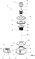
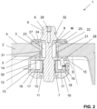
- a fastening device 1 for fastening a toilet cover to a toilet body 2 is shown.
- the toilet body 2 is typically a toilet bowl and has an opening 3 .
- an upper surface area 4 adjoins the opening 3 laterally and below the opening 3 a lower surface area 5 adjoins the opening 3 laterally.
- the fastening device 1 is clamped between the upper surface area 4 and the lower surface area 5 and is thus fixed to the toilet body 2 . Parts of the fastening device 1 are passed through the opening 3 in the process.
- the fastening device 1 comprises a fastening element 6 extending along a central axis M, a nut element 10 and a housing 12.
- the fastening element 6 has an external thread 7, a flange section 8 and a bearing section 9.
- the flange section 8 serves to bear on the upper surface area 4.
- the bearing can be direct or, as shown in the figures, indirect.
- the bearing section 9 extends from the flange section 8 in the assembled state further up away from the upper surface area 4.
- the bearing section 9 is designed as a cylindrical bearing section 9 .
- the bearing section 9 serves here as a plug-in body for accommodating corresponding hinge parts of a toilet cover, for example a toilet seat ring and/or a toilet lid.
- the bearing section 9 can also be designed differently.
- the bearing section 9 also has a drive section 26 .
- the drive section 26 is designed here as a hexagon socket and is used to hold a tool for tightening the fastening element 6.
- the bearing section 9 also includes a locking ring 32 here.
- the nut element 10 has an internal thread 11 .
- the external thread 7 of the fastening element 6 engages in the internal thread 11 .
- the fastening device 1 can be clamped in relation to the toilet body 2 via this threaded connection.
- the housing 12 has a receiving space 13 .
- the nut element 10 is at least partially rotatably mounted. This means that the nut element 10 is either mounted completely non-rotatably in the housing 12 or slight rotations are possible within a predetermined play.
- the housing 12 has a fastening structure 14 .
- the housing 12 can be fixed to the toilet body 2 with the fixing structure 14 .
- the fastening structure 14 allows the housing 12 with the nut element 10 to be pre-assembled to the toilet body 2 before the fastening element 6 engages with the external thread 7 in the internal thread 11 of the nut element 10 .
- This attachment via the attachment structure 14 also has the advantage that during cleaning work, during which the attachment element 6 may be pulled out of the internal thread 11 of the nut element 10, the housing 12 is still connected to the toilet body 2 and therefore does not fall away from the toilet body 2 can.
- the housing 12 has a stop surface 15 with which the housing 12 can be placed directly or indirectly on the lower surface area 5 .
- a sealing disk 27 is also arranged below the washer 25 .
- the sealing disk 27 is typically made of a soft material such as rubber or silicone.
- the sealing disk 27 has two different functions. On the one hand, scratching of the upper surface area 4 by the washer 25 can be avoided. On the other hand, the sealing disk 27 acts as a sealing disk, so that no cleaning liquid can get into the opening 3 during cleaning work in which the fastening element 6 is not removed.
- a disk 28 is arranged in the lower area between the stop surface 15 and the lower surface area 5 .
- the disk 28 is preferably also made of a soft material, such as rubber or silicone, and serves to increase the friction between the lower surface area 5 and the stop surface 15, so that when the fastening element 6 is actuated, the housing 12 with the nut element 10 can't turn.
- optional engagement prongs 29 protrude from the stop surface 15 and engage in the disk 28 accordingly.
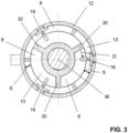
- the nut element 10 is, as of the figures 2 and 3 can be recognized, stored transversely to the central axis M in the receiving space 13 with lateral play S. This means that the nut element 10 can move within the housing 12 when the housing 12 is stationary, resulting in a movement of the nut element 10 relative to the opening 3 in the toilet body 2.
- the lateral play S is in the figures 2 and 3 marked accordingly.
- the play S is particularly preferably in the range from 2 to 10 millimeters, in particular in the range from 3 to 8 millimeters. Depending on the diameter of the opening 3, other dimensions are also conceivable.
- the nut element 10 has at least one web section 30 on the nut element side for the non-rotatable mounting.
- the housing 12 has a web section 16 on the housing side that extends into the receiving space 13 .
- the two web sections 30, 16 can be brought into contact with one another in such a way that when the fastening element 6 is screwed in or unscrewed, the nut element 10 in the housing 12 can be prevented from spinning.
- FIG 3 it is shown that in each case three web sections 30, 16 are distributed at equal intervals around the circumference of the central axis M.
- the web sections 16, 30 each extend radially to the central axis M and are designed in such a way that in every position of the nut element 10 in the housing 12, which can vary due to the lateral play S, as described above, a stop between at least one pair of web sections 16 , 30 can be reached in any position of the nut element 10 in the housing 12.
- the nut element 10 is mounted firmly in the receiving space 13 with respect to a movement in the direction of the central axis M. This means that the nut element 10 can only be moved in a direction transverse to the central axis M in the receiving space 13 .
- the nut element 10 has a flange section 17 on the outside, which protrudes into a lateral receiving area 18 in the receiving space 13 .
- the flange section 17 protrudes into the receiving space 18 in such a way that a movement of the nut element 10 in the direction of the central axis M is made impossible. This projection of the flange portion 17 in the receiving area 18 is in the figure 2 shown.
- the housing 12 also has a cover 19 with which the receiving space 13 is closed. When the cover 19 is removed, access to the receiving space 13 is created, so that the nut element 10 can be inserted into the receiving space 13 accordingly.
- the cover 19 is connected to the remaining part of the housing 12 via snap-in connection elements 31 .
- the fastening structure 14 can be firmly connected to a holding element 20 .
- the fastening structure 14 is inserted from the lower surface area 4 into the opening 3 and the retaining element 20 is removed from the upper surface area 4 pushed forth into the opening 3.
- a mechanical connection is provided between the holding element 20 and the fastening structure 14 . In the embodiment shown, this is a snap connection. However, the connection can also be a threaded connection.
- the holding element 20 can be connected to the fastening structure 14 via a mechanical connection.
- the holding element 20 has a side wall 22 which delimits a passage 23 extending along the central axis M. In the mounted position, the fastening element 6 is passed through the passage 23 and reaches the nut element 10 .
- a stop surface 24 extends laterally away from the side wall 22 . The holding element rests directly on the upper surface area 4 of the toilet body 2 via the stop surface 24 .
- the stop surface 24 of the holding element 20 is covered by the washer 25 and the sealing washer 27 .
- the attachment structure 14 is designed in such a way that the housing 12 can be attached directly to the toilet body 2 .
- spring arms (not shown) to extend away from the stop surface 15 of the housing 12, which protrude from below through the opening 3 and bear against the upper surface area 4 with corresponding undercuts.
- the embodiment shown with the holding element and the mechanical connection between the holding element 20 and the fastening structure 14 has the advantage that a clamped connection between the two surface areas 3, 4 can be provided. In this respect, a connection can already be created during assembly, so that twisting between the housing 12 and the toilet body 2 can be avoided when the external thread 7 is screwed into the internal thread 11 of the nut element 10 .
Landscapes
- Engineering & Computer Science (AREA)
- General Engineering & Computer Science (AREA)
- Mechanical Engineering (AREA)
- Health & Medical Sciences (AREA)
- Public Health (AREA)
- Toilet Supplies (AREA)
- Bidet-Like Cleaning Device And Other Flush Toilet Accessories (AREA)
Claims (14)
- Dispositif de fixation (1) pour la fixation d'un couvercle de toilettes sur un corps de toilettes (2) avec un passage (3), une zone de surface supérieure (4) se raccordant au passage (3) et une zone de surface inférieure (5) se raccordant au passage (3), comprenantun élément de fixation (6) s'étendant le long d'un axe central (M) avec un filetage extérieur (7), une section de collerette (8) pour l'appui sur la zone de surface supérieure (4) et une section de palier (9) pour le support du couvercle de toilette, etun élément d'écrou (10) avec un filetage intérieur (11) dans lequel s'engage le filetage extérieur (7),le dispositif de fixation (1) présentant en outre un boîtier (12) avec un espace de réception (13) dans lequel l'élément d'écrou (10) est logé au moins partiellement de manière non-rotative,caractérisé en ce queen ce que le boîtier (12) présente une structure de fixation (14) avec laquelle le boîtier (12) peut être fixé au corps de toilette (2), et le boîtier (12) présentant une surface de butée (15) avec laquelle le boîtier (12) peut être appliqué contre la zone de surface inférieure (5), et en ce quel'élément d'écrou (10) pour le logement non-rotatif présente au moins une section de nervure (30) côté élément d'écrou et en ce que le boîtier (12) présente une section de nervure (16) côté boîtier s'étendant dans l'espace de réception (13), les deux sections de nervure (30, 16) pouvant être amenées en contact l'une avec l'autre de telle sorte que, lors du vissage ou du dévissage de l'élément de fixation (6), l'élément d'écrou (10) puisse être empêché de tourner dans le vide.
- Dispositif de fixation (1) selon la revendication 1, caractérisé en ce que l'élément d'écrou (10) est logé dans l'espace de réception (13) avec un jeu latéral (S) transversal à l'axe central (M).
- Dispositif de fixation (1) selon la revendication 2, caractérisé en ce que le jeu (S) est compris dans la plage de 2 à 10 millimètres, en particulier dans la plage de 3 à 8 millimètres.
- Dispositif de fixation (1) selon l'une quelconque des revendications précédentes, caractérisé en ce que l'élément d'écrou (10) est monté dans l'espace de réception (13) de manière fixe par rapport à un mouvement en direction de l'axe central (M).
- Dispositif de fixation (1) selon l'une quelconque des revendications précédentes, caractérisé en ce que l'élément d'écrou (10) présente du côté extérieur une section de collerette (17) qui pénètre dans une zone de réception (18) dans l'espace de réception (13), de telle sorte qu'un mouvement de l'élément d'écrou (12) en direction de l'axe central (M) est rendu impossible.
- Dispositif de fixation (1) selon l'une quelconque des revendications précédentes, caractérisé en ce que le boîtier (12) comprend en outre un couvercle (19) avec lequel l'espace de réception (13) est fermé, le couvercle (19) pouvant être retiré du boîtier (12) de sorte qu'un accès à l'espace de réception (13) peut être créé pour l'insertion de l'élément d'écrou (10).
- Dispositif de fixation (1) selon l'une quelconque des revendications précédentes, caractérisé en ce que la structure de fixation (14) peut être reliée de manière fixe à un élément de retenue (20), lequel élément de retenue (20) peut être inséré dans le passage (3) sur le corps de toilette (2) depuis un côté opposé au boîtier (12).
- Dispositif de fixation (1) selon la revendication 7, caractérisé en ce que la structure de fixation (14) et l'élément de retenue (20) peuvent être reliés entre eux par une liaison mécanique, la liaison mécanique étant de préférence une liaison par encliquetage (21) ou une liaison filetée.
- Dispositif de fixation (1) selon l'une quelconque des revendications précédentes 7 à 8, caractérisé en ce que l'élément de retenue (20) comprend une paroi latérale (22) qui délimite un passage (23) s'étendant le long de l'axe central (M), passage (23) à travers lequel l'élément de fixation (6) est guidé, et dans lequel une surface de butée (24) s'étend à partir de la paroi latérale (22), la surface de butée (24) pouvant être appliquée directement ou indirectement contre la partie de surface supérieure (4) du corps de toilette (2).
- Dispositif de fixation (1) selon l'une des revendications précédentes 1 à 6, caractérisé en ce que la structure de fixation est conçue de telle sorte que le boîtier peut être fixé directement au corps de toilette.
- Dispositif de fixation (1) selon l'une quelconque des revendications précédentes, caractérisé en ce que la structure de fixation (14) s'étend en s'éloignant de la surface de butée (15) et de l'espace de réception (13), de telle sorte que la structure de fixation (14) pénètre dans l'ouverture (3) du corps sanitaire (2).
- Dispositif de fixation (1) selon l'une des revendications précédentes, caractérisé en ce quel'élément de fixation (6) peut être appliqué avec la section de collerette directement ou indirectement par l'intermédiaire d'une rondelle (25) sur la zone de surface supérieure (4); et/ouen ce qu'il existe entre la surface de butée (15) du boîtier (12) et la zone de surface inférieure (5) une structure augmentant le frottement entre la zone de surface inférieure (5) et la surface de butée (15).
- Ensemble comprenant un corps de toilette (2) avec un passage (3), une zone de surface supérieure (4) se raccordant au passage (3) et une zone de surface inférieure (5) se raccordant au passage (3), et un dispositif de fixation selon l'une des revendications précédentes, l'élément de fixation (6) pénétrant dans le passage (3) à partir de la zone de surface supérieure et, en face, étant en prise par filetage au niveau de la zone de surface inférieure (5) avec l'élément d'écrou (10) logé dans le boîtier (12), le boîtier (12) pouvant être amené en contact avec la zone de surface inférieure (5) par la surface de butée, et dans lequel, lors d'un serrage de l'élément de fixation (6), le dispositif de fixation peut être bloqué par rapport au corps de toilette (2).
- Procédé de montage d'un dispositif de fixation selon l'une des revendications précédentes 1 à 12 ou d'un ensemble selon la revendication 13, caractériséen ce que, dans une première étape, le boîtier (12) est fixé au corps de toilette (2) avec l'élément d'écrou (10) par l'intermédiaire de la structure de fixation, de telle sorte que la surface de butée (15) peut être amenée en contact avec la zone de surface inférieure (5),en ce que, dans une deuxième étape, l'élément de fixation (6) est guidé avec le filetage extérieur (7) à travers le passage (3) et est vissé dans le filetage intérieur (11) jusqu'à ce que la section de collerette (8) vienne en contact avec la zone de surface supérieure (4), eten ce que, dans une troisième étape, l'élément de fixation (6) est serré.
Priority Applications (2)
| Application Number | Priority Date | Filing Date | Title |
|---|---|---|---|
| EP19176403.4A EP3742009B1 (fr) | 2019-05-24 | 2019-05-24 | Dispositif de fixation pour recouvrements de toilettes |
| CH01622/19A CH715962B1 (de) | 2019-05-24 | 2019-12-13 | Befestigungsvorrichtung für Toilettenabdeckungen. |
Applications Claiming Priority (1)
| Application Number | Priority Date | Filing Date | Title |
|---|---|---|---|
| EP19176403.4A EP3742009B1 (fr) | 2019-05-24 | 2019-05-24 | Dispositif de fixation pour recouvrements de toilettes |
Publications (2)
| Publication Number | Publication Date |
|---|---|
| EP3742009A1 EP3742009A1 (fr) | 2020-11-25 |
| EP3742009B1 true EP3742009B1 (fr) | 2023-05-10 |
Family
ID=66647234
Family Applications (1)
| Application Number | Title | Priority Date | Filing Date |
|---|---|---|---|
| EP19176403.4A Active EP3742009B1 (fr) | 2019-05-24 | 2019-05-24 | Dispositif de fixation pour recouvrements de toilettes |
Country Status (2)
| Country | Link |
|---|---|
| EP (1) | EP3742009B1 (fr) |
| CH (1) | CH715962B1 (fr) |
Families Citing this family (2)
| Publication number | Priority date | Publication date | Assignee | Title |
|---|---|---|---|---|
| DE102020215474A1 (de) * | 2020-12-08 | 2022-06-09 | Volkswagen Aktiengesellschaft | Befestigungsanordnung und Verwendung einer Befestigungsanordnung |
| DE102022132678A1 (de) | 2022-12-08 | 2024-06-13 | Duravit Aktiengesellschaft | Befestigungseinrichtung für eine Sitz- oder Deckelgarnitur an einem Sanitärgegenstand sowie Sanitäranordnung umfassend einen Sanitärgegenstand und eine Sitz- oder Deckelgarnitur |
Family Cites Families (4)
| Publication number | Priority date | Publication date | Assignee | Title |
|---|---|---|---|---|
| GB495976A (en) * | 1936-06-11 | 1938-11-23 | Elastic Stop Nut Corp | Improvements in or relating to fastening devices |
| US4464091A (en) * | 1981-01-12 | 1984-08-07 | Deutsch Fastener Corp. | Captive fastener |
| US6287064B1 (en) * | 1999-12-10 | 2001-09-11 | Western Sky Industries, Inc. | Clip type fastener assembly |
| DE102014109277A1 (de) | 2014-07-02 | 2016-01-07 | Tece Gmbh | Verfahren zur Befestigung eines WC-Sitzes an einem WC-Körper sowie Vorrichtungen zur Durchführung des Verfahrens |
-
2019
- 2019-05-24 EP EP19176403.4A patent/EP3742009B1/fr active Active
- 2019-12-13 CH CH01622/19A patent/CH715962B1/de not_active IP Right Cessation
Also Published As
| Publication number | Publication date |
|---|---|
| CH715962B1 (de) | 2020-09-30 |
| EP3742009A1 (fr) | 2020-11-25 |
Similar Documents
| Publication | Publication Date | Title |
|---|---|---|
| EP3008352B1 (fr) | Système de couplage par emboîtement comportant un élément de couplage déformable élastiquement ainsi que procédé de montage associé | |
| DE60100608T2 (de) | Wasserdichte Halteöse | |
| DE19514944C1 (de) | Selbstjustierender Dämfungsanschlag für bewegliche Teile | |
| EP3745936B1 (fr) | Dispositif de fixation pour un siège de toilettes | |
| EP2108751B1 (fr) | Armature d'écoulement pour baignoire ou bac de douche dotés d'une alimentation au sol | |
| EP1245842B1 (fr) | Dispositif de fixation | |
| DE29911362U1 (de) | Anschlußarmatur zum Befestigen von länglichen Körpern | |
| EP3742009B1 (fr) | Dispositif de fixation pour recouvrements de toilettes | |
| DE19752714C2 (de) | Befestigungsanordnung für die Anbringung eines Bauteils an einer C-förmigen Halteschiene | |
| DE4138144C2 (de) | Einstellbare, planeben montierbare Befestigungseinrichtung | |
| DE102015120525B4 (de) | Befestigungssystem für einen Toilettensitz, Käfig, Käfigmutter, Verwendung, Anordnung und Verfahren | |
| EP1002907A1 (fr) | Armature sanitaire | |
| DE4408733B4 (de) | Wischarm für eine Scheibenwischeranlage, insbesondere für Kraftfahrzeuge | |
| EP3667010A1 (fr) | Dispositif de butée pour un joint de porte automatique, en particulier pour une porte pivotante ou battante, agencement d'un joint de porte automatique et d'un dispositif de butée | |
| DE202021104030U1 (de) | Befestigungsvorrichtung für Wasserhähne | |
| EP3354808A1 (fr) | Garniture d'évacuation pourvue de bouchon de vidange pouvant être soulevé et abaissé | |
| EP1321636B1 (fr) | Bouchon pour réservoir à liquide en particulier pour carter d'huile de moteur à combustion | |
| EP2265831B1 (fr) | Pièce de vissage pour une fixation d'une jante d'une automobile | |
| EP0997097B1 (fr) | Dispositif de fixation de lunettes et/ou de couvercles de cuvettes de toilettes | |
| DE10341058B3 (de) | Entlüfterkopf für Heizkörper | |
| EP0730839B1 (fr) | Dispositif de fixation pour une poignée d'une baignoire ou similaire | |
| EP3272954A1 (fr) | Système d'évacuation | |
| EP0955220B1 (fr) | bras pour système d'essuie-glace | |
| EP1803187A1 (fr) | Dispositif de fixation d'une antenne | |
| DE102012025165A1 (de) | Befestigungsvorrichtung |
Legal Events
| Date | Code | Title | Description |
|---|---|---|---|
| PUAI | Public reference made under article 153(3) epc to a published international application that has entered the european phase |
Free format text: ORIGINAL CODE: 0009012 |
|
| STAA | Information on the status of an ep patent application or granted ep patent |
Free format text: STATUS: THE APPLICATION HAS BEEN PUBLISHED |
|
| AK | Designated contracting states |
Kind code of ref document: A1 Designated state(s): AL AT BE BG CH CY CZ DE DK EE ES FI FR GB GR HR HU IE IS IT LI LT LU LV MC MK MT NL NO PL PT RO RS SE SI SK SM TR |
|
| AX | Request for extension of the european patent |
Extension state: BA ME |
|
| STAA | Information on the status of an ep patent application or granted ep patent |
Free format text: STATUS: REQUEST FOR EXAMINATION WAS MADE |
|
| 17P | Request for examination filed |
Effective date: 20210325 |
|
| RBV | Designated contracting states (corrected) |
Designated state(s): AL AT BE BG CH CY CZ DE DK EE ES FI FR GB GR HR HU IE IS IT LI LT LU LV MC MK MT NL NO PL PT RO RS SE SI SK SM TR |
|
| GRAP | Despatch of communication of intention to grant a patent |
Free format text: ORIGINAL CODE: EPIDOSNIGR1 |
|
| STAA | Information on the status of an ep patent application or granted ep patent |
Free format text: STATUS: GRANT OF PATENT IS INTENDED |
|
| RIC1 | Information provided on ipc code assigned before grant |
Ipc: F16B 43/00 20060101ALN20221114BHEP Ipc: F16B 41/00 20060101ALI20221114BHEP Ipc: F16B 5/06 20060101ALI20221114BHEP Ipc: F16B 37/04 20060101AFI20221114BHEP |
|
| INTG | Intention to grant announced |
Effective date: 20221209 |
|
| GRAS | Grant fee paid |
Free format text: ORIGINAL CODE: EPIDOSNIGR3 |
|
| GRAA | (expected) grant |
Free format text: ORIGINAL CODE: 0009210 |
|
| STAA | Information on the status of an ep patent application or granted ep patent |
Free format text: STATUS: THE PATENT HAS BEEN GRANTED |
|
| AK | Designated contracting states |
Kind code of ref document: B1 Designated state(s): AL AT BE BG CH CY CZ DE DK EE ES FI FR GB GR HR HU IE IS IT LI LT LU LV MC MK MT NL NO PL PT RO RS SE SI SK SM TR |
|
| REG | Reference to a national code |
Ref country code: GB Ref legal event code: FG4D Free format text: NOT ENGLISH |
|
| REG | Reference to a national code |
Ref country code: AT Ref legal event code: REF Ref document number: 1566936 Country of ref document: AT Kind code of ref document: T Effective date: 20230515 Ref country code: CH Ref legal event code: EP |
|
| REG | Reference to a national code |
Ref country code: DE Ref legal event code: R096 Ref document number: 502019007666 Country of ref document: DE |
|
| REG | Reference to a national code |
Ref country code: IE Ref legal event code: FG4D Free format text: LANGUAGE OF EP DOCUMENT: GERMAN |
|
| P01 | Opt-out of the competence of the unified patent court (upc) registered |
Effective date: 20230523 |
|
| REG | Reference to a national code |
Ref country code: LT Ref legal event code: MG9D |
|
| REG | Reference to a national code |
Ref country code: NL Ref legal event code: MP Effective date: 20230510 |
|
| PG25 | Lapsed in a contracting state [announced via postgrant information from national office to epo] |
Ref country code: SE Free format text: LAPSE BECAUSE OF FAILURE TO SUBMIT A TRANSLATION OF THE DESCRIPTION OR TO PAY THE FEE WITHIN THE PRESCRIBED TIME-LIMIT Effective date: 20230510 Ref country code: PT Free format text: LAPSE BECAUSE OF FAILURE TO SUBMIT A TRANSLATION OF THE DESCRIPTION OR TO PAY THE FEE WITHIN THE PRESCRIBED TIME-LIMIT Effective date: 20230911 Ref country code: NO Free format text: LAPSE BECAUSE OF FAILURE TO SUBMIT A TRANSLATION OF THE DESCRIPTION OR TO PAY THE FEE WITHIN THE PRESCRIBED TIME-LIMIT Effective date: 20230810 Ref country code: NL Free format text: LAPSE BECAUSE OF FAILURE TO SUBMIT A TRANSLATION OF THE DESCRIPTION OR TO PAY THE FEE WITHIN THE PRESCRIBED TIME-LIMIT Effective date: 20230510 Ref country code: ES Free format text: LAPSE BECAUSE OF FAILURE TO SUBMIT A TRANSLATION OF THE DESCRIPTION OR TO PAY THE FEE WITHIN THE PRESCRIBED TIME-LIMIT Effective date: 20230510 |
|
| PG25 | Lapsed in a contracting state [announced via postgrant information from national office to epo] |
Ref country code: RS Free format text: LAPSE BECAUSE OF FAILURE TO SUBMIT A TRANSLATION OF THE DESCRIPTION OR TO PAY THE FEE WITHIN THE PRESCRIBED TIME-LIMIT Effective date: 20230510 Ref country code: PL Free format text: LAPSE BECAUSE OF FAILURE TO SUBMIT A TRANSLATION OF THE DESCRIPTION OR TO PAY THE FEE WITHIN THE PRESCRIBED TIME-LIMIT Effective date: 20230510 Ref country code: LV Free format text: LAPSE BECAUSE OF FAILURE TO SUBMIT A TRANSLATION OF THE DESCRIPTION OR TO PAY THE FEE WITHIN THE PRESCRIBED TIME-LIMIT Effective date: 20230510 Ref country code: LT Free format text: LAPSE BECAUSE OF FAILURE TO SUBMIT A TRANSLATION OF THE DESCRIPTION OR TO PAY THE FEE WITHIN THE PRESCRIBED TIME-LIMIT Effective date: 20230510 Ref country code: IS Free format text: LAPSE BECAUSE OF FAILURE TO SUBMIT A TRANSLATION OF THE DESCRIPTION OR TO PAY THE FEE WITHIN THE PRESCRIBED TIME-LIMIT Effective date: 20230910 Ref country code: HR Free format text: LAPSE BECAUSE OF FAILURE TO SUBMIT A TRANSLATION OF THE DESCRIPTION OR TO PAY THE FEE WITHIN THE PRESCRIBED TIME-LIMIT Effective date: 20230510 Ref country code: GR Free format text: LAPSE BECAUSE OF FAILURE TO SUBMIT A TRANSLATION OF THE DESCRIPTION OR TO PAY THE FEE WITHIN THE PRESCRIBED TIME-LIMIT Effective date: 20230811 |
|
| PG25 | Lapsed in a contracting state [announced via postgrant information from national office to epo] |
Ref country code: FI Free format text: LAPSE BECAUSE OF FAILURE TO SUBMIT A TRANSLATION OF THE DESCRIPTION OR TO PAY THE FEE WITHIN THE PRESCRIBED TIME-LIMIT Effective date: 20230510 |
|
| PG25 | Lapsed in a contracting state [announced via postgrant information from national office to epo] |
Ref country code: SK Free format text: LAPSE BECAUSE OF FAILURE TO SUBMIT A TRANSLATION OF THE DESCRIPTION OR TO PAY THE FEE WITHIN THE PRESCRIBED TIME-LIMIT Effective date: 20230510 |
|
| REG | Reference to a national code |
Ref country code: BE Ref legal event code: MM Effective date: 20230531 |
|
| PG25 | Lapsed in a contracting state [announced via postgrant information from national office to epo] |
Ref country code: SM Free format text: LAPSE BECAUSE OF FAILURE TO SUBMIT A TRANSLATION OF THE DESCRIPTION OR TO PAY THE FEE WITHIN THE PRESCRIBED TIME-LIMIT Effective date: 20230510 Ref country code: SK Free format text: LAPSE BECAUSE OF FAILURE TO SUBMIT A TRANSLATION OF THE DESCRIPTION OR TO PAY THE FEE WITHIN THE PRESCRIBED TIME-LIMIT Effective date: 20230510 Ref country code: RO Free format text: LAPSE BECAUSE OF FAILURE TO SUBMIT A TRANSLATION OF THE DESCRIPTION OR TO PAY THE FEE WITHIN THE PRESCRIBED TIME-LIMIT Effective date: 20230510 Ref country code: EE Free format text: LAPSE BECAUSE OF FAILURE TO SUBMIT A TRANSLATION OF THE DESCRIPTION OR TO PAY THE FEE WITHIN THE PRESCRIBED TIME-LIMIT Effective date: 20230510 Ref country code: DK Free format text: LAPSE BECAUSE OF FAILURE TO SUBMIT A TRANSLATION OF THE DESCRIPTION OR TO PAY THE FEE WITHIN THE PRESCRIBED TIME-LIMIT Effective date: 20230510 Ref country code: CZ Free format text: LAPSE BECAUSE OF FAILURE TO SUBMIT A TRANSLATION OF THE DESCRIPTION OR TO PAY THE FEE WITHIN THE PRESCRIBED TIME-LIMIT Effective date: 20230510 Ref country code: LU Free format text: LAPSE BECAUSE OF NON-PAYMENT OF DUE FEES Effective date: 20230524 |
|
| REG | Reference to a national code |
Ref country code: DE Ref legal event code: R097 Ref document number: 502019007666 Country of ref document: DE |
|
| PG25 | Lapsed in a contracting state [announced via postgrant information from national office to epo] |
Ref country code: MC Free format text: LAPSE BECAUSE OF FAILURE TO SUBMIT A TRANSLATION OF THE DESCRIPTION OR TO PAY THE FEE WITHIN THE PRESCRIBED TIME-LIMIT Effective date: 20230510 |
|
| REG | Reference to a national code |
Ref country code: IE Ref legal event code: MM4A |
|
| PG25 | Lapsed in a contracting state [announced via postgrant information from national office to epo] |
Ref country code: MC Free format text: LAPSE BECAUSE OF FAILURE TO SUBMIT A TRANSLATION OF THE DESCRIPTION OR TO PAY THE FEE WITHIN THE PRESCRIBED TIME-LIMIT Effective date: 20230510 |
|
| PLBE | No opposition filed within time limit |
Free format text: ORIGINAL CODE: 0009261 |
|
| STAA | Information on the status of an ep patent application or granted ep patent |
Free format text: STATUS: NO OPPOSITION FILED WITHIN TIME LIMIT |
|
| PG25 | Lapsed in a contracting state [announced via postgrant information from national office to epo] |
Ref country code: IE Free format text: LAPSE BECAUSE OF NON-PAYMENT OF DUE FEES Effective date: 20230524 |
|
| 26N | No opposition filed |
Effective date: 20240213 |
|
| GBPC | Gb: european patent ceased through non-payment of renewal fee |
Effective date: 20230810 |
|
| PG25 | Lapsed in a contracting state [announced via postgrant information from national office to epo] |
Ref country code: IE Free format text: LAPSE BECAUSE OF NON-PAYMENT OF DUE FEES Effective date: 20230524 |
|
| PG25 | Lapsed in a contracting state [announced via postgrant information from national office to epo] |
Ref country code: SI Free format text: LAPSE BECAUSE OF FAILURE TO SUBMIT A TRANSLATION OF THE DESCRIPTION OR TO PAY THE FEE WITHIN THE PRESCRIBED TIME-LIMIT Effective date: 20230510 |
|
| PG25 | Lapsed in a contracting state [announced via postgrant information from national office to epo] |
Ref country code: SI Free format text: LAPSE BECAUSE OF FAILURE TO SUBMIT A TRANSLATION OF THE DESCRIPTION OR TO PAY THE FEE WITHIN THE PRESCRIBED TIME-LIMIT Effective date: 20230510 Ref country code: IT Free format text: LAPSE BECAUSE OF FAILURE TO SUBMIT A TRANSLATION OF THE DESCRIPTION OR TO PAY THE FEE WITHIN THE PRESCRIBED TIME-LIMIT Effective date: 20230510 Ref country code: FR Free format text: LAPSE BECAUSE OF NON-PAYMENT OF DUE FEES Effective date: 20230710 Ref country code: BE Free format text: LAPSE BECAUSE OF NON-PAYMENT OF DUE FEES Effective date: 20230531 |
|
| PG25 | Lapsed in a contracting state [announced via postgrant information from national office to epo] |
Ref country code: GB Free format text: LAPSE BECAUSE OF NON-PAYMENT OF DUE FEES Effective date: 20230810 |
|
| PG25 | Lapsed in a contracting state [announced via postgrant information from national office to epo] |
Ref country code: GB Free format text: LAPSE BECAUSE OF NON-PAYMENT OF DUE FEES Effective date: 20230810 |
|
| PG25 | Lapsed in a contracting state [announced via postgrant information from national office to epo] |
Ref country code: BG Free format text: LAPSE BECAUSE OF FAILURE TO SUBMIT A TRANSLATION OF THE DESCRIPTION OR TO PAY THE FEE WITHIN THE PRESCRIBED TIME-LIMIT Effective date: 20230510 |
|
| PG25 | Lapsed in a contracting state [announced via postgrant information from national office to epo] |
Ref country code: BG Free format text: LAPSE BECAUSE OF FAILURE TO SUBMIT A TRANSLATION OF THE DESCRIPTION OR TO PAY THE FEE WITHIN THE PRESCRIBED TIME-LIMIT Effective date: 20230510 |
|
| REG | Reference to a national code |
Ref country code: AT Ref legal event code: PC Ref document number: 1566936 Country of ref document: AT Kind code of ref document: T Owner name: GEBERIT INTERNATIONAL AG, CH Effective date: 20241118 |
|
| PGFP | Annual fee paid to national office [announced via postgrant information from national office to epo] |
Ref country code: DE Payment date: 20250521 Year of fee payment: 7 |
|
| PGFP | Annual fee paid to national office [announced via postgrant information from national office to epo] |
Ref country code: CH Payment date: 20250601 Year of fee payment: 7 |
|
| PGFP | Annual fee paid to national office [announced via postgrant information from national office to epo] |
Ref country code: AT Payment date: 20250522 Year of fee payment: 7 |
|
| PG25 | Lapsed in a contracting state [announced via postgrant information from national office to epo] |
Ref country code: CY Free format text: LAPSE BECAUSE OF FAILURE TO SUBMIT A TRANSLATION OF THE DESCRIPTION OR TO PAY THE FEE WITHIN THE PRESCRIBED TIME-LIMIT; INVALID AB INITIO Effective date: 20190524 |
|
| PG25 | Lapsed in a contracting state [announced via postgrant information from national office to epo] |
Ref country code: HU Free format text: LAPSE BECAUSE OF FAILURE TO SUBMIT A TRANSLATION OF THE DESCRIPTION OR TO PAY THE FEE WITHIN THE PRESCRIBED TIME-LIMIT; INVALID AB INITIO Effective date: 20190524 |
|
| PG25 | Lapsed in a contracting state [announced via postgrant information from national office to epo] |
Ref country code: TR Free format text: LAPSE BECAUSE OF FAILURE TO SUBMIT A TRANSLATION OF THE DESCRIPTION OR TO PAY THE FEE WITHIN THE PRESCRIBED TIME-LIMIT Effective date: 20230510 |