EP4382811A1 - Dispositif de production de vapeur et appareil ménager à circulation d'eau doté d'un tel dispositif - Google Patents
Dispositif de production de vapeur et appareil ménager à circulation d'eau doté d'un tel dispositif Download PDFInfo
- Publication number
- EP4382811A1 EP4382811A1 EP23213070.8A EP23213070A EP4382811A1 EP 4382811 A1 EP4382811 A1 EP 4382811A1 EP 23213070 A EP23213070 A EP 23213070A EP 4382811 A1 EP4382811 A1 EP 4382811A1
- Authority
- EP
- European Patent Office
- Prior art keywords
- heating element
- housing
- heating
- tub
- heating chamber
- Prior art date
- Legal status (The legal status is an assumption and is not a legal conclusion. Google has not performed a legal analysis and makes no representation as to the accuracy of the status listed.)
- Granted
Links
Images

Classifications
-
- F—MECHANICAL ENGINEERING; LIGHTING; HEATING; WEAPONS; BLASTING
- F24—HEATING; RANGES; VENTILATING
- F24C—DOMESTIC STOVES OR RANGES ; DETAILS OF DOMESTIC STOVES OR RANGES, OF GENERAL APPLICATION
- F24C15/00—Details
- F24C15/32—Arrangements of ducts for hot gases, e.g. in or around baking ovens
- F24C15/322—Arrangements of ducts for hot gases, e.g. in or around baking ovens with forced circulation
- F24C15/327—Arrangements of ducts for hot gases, e.g. in or around baking ovens with forced circulation with air moisturising
-
- F—MECHANICAL ENGINEERING; LIGHTING; HEATING; WEAPONS; BLASTING
- F22—STEAM GENERATION
- F22B—METHODS OF STEAM GENERATION; STEAM BOILERS
- F22B1/00—Methods of steam generation characterised by form of heating method
- F22B1/28—Methods of steam generation characterised by form of heating method in boilers heated electrically
-
- A—HUMAN NECESSITIES
- A47—FURNITURE; DOMESTIC ARTICLES OR APPLIANCES; COFFEE MILLS; SPICE MILLS; SUCTION CLEANERS IN GENERAL
- A47J—KITCHEN EQUIPMENT; COFFEE MILLS; SPICE MILLS; APPARATUS FOR MAKING BEVERAGES
- A47J27/00—Cooking-vessels
- A47J27/04—Cooking-vessels for cooking food in steam; Devices for extracting fruit juice by means of steam ; Vacuum cooking vessels
-
- F—MECHANICAL ENGINEERING; LIGHTING; HEATING; WEAPONS; BLASTING
- F22—STEAM GENERATION
- F22B—METHODS OF STEAM GENERATION; STEAM BOILERS
- F22B1/00—Methods of steam generation characterised by form of heating method
- F22B1/28—Methods of steam generation characterised by form of heating method in boilers heated electrically
- F22B1/284—Methods of steam generation characterised by form of heating method in boilers heated electrically with water in reservoirs
-
- F—MECHANICAL ENGINEERING; LIGHTING; HEATING; WEAPONS; BLASTING
- F24—HEATING; RANGES; VENTILATING
- F24C—DOMESTIC STOVES OR RANGES ; DETAILS OF DOMESTIC STOVES OR RANGES, OF GENERAL APPLICATION
- F24C15/00—Details
- F24C15/003—Details moisturising of air
-
- H—ELECTRICITY
- H05—ELECTRIC TECHNIQUES NOT OTHERWISE PROVIDED FOR
- H05B—ELECTRIC HEATING; ELECTRIC LIGHT SOURCES NOT OTHERWISE PROVIDED FOR; CIRCUIT ARRANGEMENTS FOR ELECTRIC LIGHT SOURCES, IN GENERAL
- H05B3/00—Ohmic-resistance heating
- H05B3/02—Details
- H05B3/06—Heater elements structurally combined with coupling elements or holders
-
- A—HUMAN NECESSITIES
- A21—BAKING; EDIBLE DOUGHS
- A21B—BAKERS' OVENS; MACHINES OR EQUIPMENT FOR BAKING
- A21B3/00—Parts or accessories of ovens
- A21B3/04—Air-treatment devices for ovens, e.g. regulating humidity
-
- A—HUMAN NECESSITIES
- A47—FURNITURE; DOMESTIC ARTICLES OR APPLIANCES; COFFEE MILLS; SPICE MILLS; SUCTION CLEANERS IN GENERAL
- A47J—KITCHEN EQUIPMENT; COFFEE MILLS; SPICE MILLS; APPARATUS FOR MAKING BEVERAGES
- A47J27/00—Cooking-vessels
- A47J27/04—Cooking-vessels for cooking food in steam; Devices for extracting fruit juice by means of steam ; Vacuum cooking vessels
- A47J2027/043—Cooking-vessels for cooking food in steam; Devices for extracting fruit juice by means of steam ; Vacuum cooking vessels for cooking food in steam
-
- H—ELECTRICITY
- H05—ELECTRIC TECHNIQUES NOT OTHERWISE PROVIDED FOR
- H05B—ELECTRIC HEATING; ELECTRIC LIGHT SOURCES NOT OTHERWISE PROVIDED FOR; CIRCUIT ARRANGEMENTS FOR ELECTRIC LIGHT SOURCES, IN GENERAL
- H05B2203/00—Aspects relating to Ohmic resistive heating covered by group H05B3/00
- H05B2203/013—Heaters using resistive films or coatings
-
- H—ELECTRICITY
- H05—ELECTRIC TECHNIQUES NOT OTHERWISE PROVIDED FOR
- H05B—ELECTRIC HEATING; ELECTRIC LIGHT SOURCES NOT OTHERWISE PROVIDED FOR; CIRCUIT ARRANGEMENTS FOR ELECTRIC LIGHT SOURCES, IN GENERAL
- H05B2203/00—Aspects relating to Ohmic resistive heating covered by group H05B3/00
- H05B2203/021—Heaters specially adapted for heating liquids
Definitions
- the invention relates to a device for generating steam, which is also known as a so-called steam generator, as well as a water-conducting household appliance with such a device for generating steam, which is also known as a so-called steam cooker, steamer or steam oven.
- the device for generating steam has a housing with a heating chamber and heating element therein, with a water inlet leading into the heating chamber and a steam outlet leading out.
- Such devices are known, for example from EN 10 2018 217 645 A1 or the EP 1 975 517 A1 . They are each designed to heat and evaporate a certain amount of water in a tank. The steam generated is then introduced into a preparation chamber or muffle of the household appliance in question in order to prepare food with steam and thus gently.
- the invention is based on the object of creating a device for generating steam as mentioned above and a water-conducting household appliance provided therewith, with which problems of the prior art can be avoided and in particular it is possible to design the device for generating steam in a simple and reliable manner and to integrate it well into a household appliance.
- the device for generating steam has a housing and therein a heating chamber for water, which has a water inlet for connection to a water supply, for example a water tank or a water pipe.
- the heating chamber also has a steam outlet that directs steam by means of a hose or pipe into a preparation chamber of a water-conducting household appliance or steam oven.
- a heating element is arranged or provided on the heating chamber for heating and evaporating water in the heating chamber.
- the heating element has a heating element carrier and heating conductors arranged thereon.
- the heating element can advantageously be designed as a thick-film heating element with thick-film heating conductors.
- the heating chamber and the heating element are arranged in the housing, with the heating element preferably forming only part of the heating chamber.
- the heating element forms a wall of the heating chamber or only a single wall, and is connected to other walls of the heating chamber in a sealing manner, preferably by pressing plus sealing.
- the heating element and these other walls together form the closed heating chamber, which has the water inlet and the steam outlet as the only openings.
- the heating element carrier is made of metal, although the other walls of the heating chamber and the housing are preferably made of plastic, which makes it easy to manufacture.
- the heating chamber is longer than it is wide in one direction of extension, which direction of extension is the vertical direction after installation in the household appliance.
- the heating chamber has an even smaller depth. This advantageously applies not only to the heating chamber, but to the entire device or its housing.
- An electrical connection device for the device and in particular for the heating element is provided laterally on an elongated side of the heating chamber on the housing, in particular it protrudes laterally from the housing. This lateral arrangement of the connection device ensures that it at least increases the aforementioned depth. When installed in a household appliance according to the invention, it can thus be achieved that the depth increases slightly due to the depth of the housing, without the connection device contributing to this.
- connection device can be designed as a plug connection device, whereby it can have plug connection lugs and/or plug connection sockets. These can be connected to the heating element electrically and/or structurally or mechanically and thus bring about contact, advantageously by contacting or pressing. This can either be permanent or simply by contacting or pressing. Alternatively, screw connections could also be provided.
- an electrical contact from the connection device to the heating element or to the heating conductors can be provided on the side of the heating element facing away from the heating chamber, which is advantageously a dry side of the heating element.
- the side of the heating element facing the heating chamber forms a wall of the heating chamber and is thus at least partially covered with water or steam.
- An electrical contact can have contact fields that are connected to the heating conductors.
- Spring-loaded contact arms of the connection device can be pressed onto the contact fields and thus establish the contact. These contact arms preferably run parallel to and next to one another; a distance can be a few millimeters.
- the contact arms can be identical. Alternatively, they can be of different thicknesses or widths, depending on the current or electrical power to be transmitted.
- the heating chamber is flat and the housing is flat too, with the electrical connection device protruding from a narrow side of the flat housing. This has already been mentioned previously.
- the heating element can be curved like a groove away from the heating chamber in such a way that a peak line of the curvature runs along the direction of extension in the length of the device.
- This curvature allows the heating element to be stable and to curve or expand in a predetermined direction when heated.
- the heated area can be slightly enlarged due to the curvature.
- the curvature of the heating element corresponds to or makes up between 5% and 20% of the width of the heating element.
- the heating element can preferably have a rectangular shape in plan view, which is an easy shape to produce. It also makes it possible to form several individual heating elements simply and efficiently from a given panel.
- the curvature can be a uniform curve, so that the heating element can be part of a tube as a panel.
- the heating element can be a jacket section of 5% to 20% of an entire pipe or, depending on the desired or accepted curvature, 5 to 20 heating elements can be cut out of a round pipe.
- the housing can have an elongated tub for the heating chamber, into which the water inlet and the steam outlet open.
- This tub can have a constant cross-section or constant curvature.
- the tub advantageously has lateral tub walls and a surrounding tub rim.
- the heating element can be in sealing contact with this surrounding tub rim in such a way that the The tub and the heating element form the heating chamber and completely enclose it. Since the heating chamber should preferably be flat, as explained above, the water inlet and/or the steam outlet open into the heating chamber on the short, flat sides. This has the advantage, among other things, that they do not cover or use up any surface area where the heating element is preferably located. This means that the surface area can be as large as possible.
- a groove with a seal located in it can run around the edge of the tub, with the heating element resting all around against this seal, advantageously with sufficient pressure, and thereby providing the sealing function.
- This seal should be temperature-resistant due to the expected temperatures of the heating element, so it can advantageously be made of silicone or EPDM. It can be inserted into the groove mentioned as a separately manufactured seal, whereby it can be designed as a round cord seal or can be adapted to the specific shape of the groove. Alternatively, the seal can be injection-molded onto the edge of the tub, which simplifies assembly of the device.
- PPS is a suitable plastic material for the plastic of the tub itself, as it can withstand long-term temperatures of around 160 °C and, at peak times, even temperatures over 200 °C.
- the housing advantageously has an upper housing part which is attached to the tub, which preferably forms a lower housing part, in such a way that the upper housing part presses the heating element against the tub or against the aforementioned seal.
- the upper housing part can have a circumferential pressure rib or a projection which lie opposite the tub edge or the seal or which run outside the tub edge above the aforementioned seal.
- Such a pressure rib or this projection can preferably run continuously so that they press the heating element against the continuous tub edge or against the seal all the way around. This not only ensures the mechanical cohesion of the housing or the device, but above all the tightness of the heating chamber so that neither water nor steam escapes.
- the tub or a housing top part can have support projections or stops on the side outside the surrounding tub edge, against which the heating element rests with a side edge, in particular the side edges at the end of the curvature. In this way, the position of the heating element in the device and on the tub can be secured, which is important for a precise and easy-to-establish connection.
- a housing upper part is advantageously detachably attached to the tub, with a snap-in connection or a clip connection being provided in particular for this purpose.
- fastening can advantageously be provided all the way around the heating chamber. This is particularly advantageously also provided in or near the end areas of the heating chamber close to the water inlet/steam outlet.
- the electrical connection device is designed with a connection housing on a housing upper part, wherein in particular the connection housing is molded or injection-molded onto it in one piece.
- the connection housing should not protrude or protrude beyond the housing in the direction of thickness, so that the device does not become thicker due to the electrical connection device or the connection housing.
- connection housing can be open on or towards at least one side, whereby plug units can be pushed into the connection housing from this side and can then be detachably fastened therein.
- plug units can be fastened therein by means of a locking device, i.e. can be locked in place.
- the plug units are electrically contacted with the heating element, advantageously by means of the contact arms described above.
- the plug units can in particular be plastic housings in which plug connection lugs or plug connection sockets can be arranged. Alternatively, the plug units can be held as plug connection lugs or plug connection sockets in a holding part made of plastic.
- the plug connection lugs or plug connection sockets can be provided with contact arms, for example molded, fastened or welded, which protrude in the insertion direction.
- the holding part can be designed so that it can be pushed into the connection housing, whereby it can then be detachably fastened therein. It can be fastened by means of a locking device.
- the upper housing part can run at a small distance above the heating element, whereby a distance can be between 1 mm and 20 mm.
- the upper housing part can have ventilation openings for ventilation or cooling of the heating element, as is known per se.
- the upper housing part in the area above the heating element can be largely honeycomb-shaped with webs and honeycomb-shaped spaces in between. This enables good ventilation and also achieves sufficient stability.
- a knitted fabric made of thin material can be arranged in the heating chamber, in particular with or made of wire or plastic threads. This can be arranged in at least one area close to the steam outlet and/or the water inlet. This can reduce calcification in the heating chamber. In addition, excessive bubbling in the heating chamber can be avoided when the water in it is boiling.
- a water-conducting household appliance which is designed in particular as a steam oven or as a steam cooker, has an outer housing and a preparation chamber for preparing food using steam, preferably hot steam.
- a previously described device for generating steam is arranged outside the preparation chamber and in particular behind it within the outer housing. This device for generating steam is arranged upright in its longitudinal direction. A steam outlet can be at the top of the device so that steam can easily flow out.
- the device for generating steam is preferably flat and arranged with a flat side facing the preparation chamber so that the installation depth is as small as possible.
- a steam oven 11 according to the invention is shown as a water-conducting household appliance in a very simplified rear view, in particular without a cover that is advantageously provided, as is known per se from the prior art.
- the steam oven 11 has a housing 12, in the interior of which an oven muffle (not shown here but known from the prior art) is arranged as the preparation space mentioned at the beginning.
- a steam generator 21 according to the invention is arranged on a rear side 13 of the steam oven 11. It can advantageously be covered by a cover above it and thus protected from damage.
- the steam generator 21 has a water hose 15 as a connection, which is led in from below.
- a steam line 17 leads out of the top of the steam generator 21 and leads into the preparation space mentioned. Thermal insulation is advantageously provided around the steam generator 21, or at least towards the housing 12 of the steam oven 11.
- the steam generator 21 is connected electrically by means of a plug 18 with a connecting cable 19, preferably to a control and/or power supply. This will be explained below.
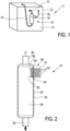
- the steam generator 21 is a relatively flat and elongated and according to Fig.1 upright mounted housing 22, see also the Fig. 3
- the steam generator 21 is approximately three times as long as it is wide and according to Fig. 3 it or at least a heating chamber 28 formed inside is approximately twice as wide as it is thick. It is thus clear that the steam generator 21 is connected to the steam oven 11 according to Fig.1 When installed, the installation depth is increased as little as possible towards the rear. It can also be offset further to the side, for example, to accommodate a drive motor for a recirculation fan.
- the housing 22 of the steam generator 21 has a water inlet 24 as a nozzle at the bottom, to which the water hose 15 is connected in a sealed manner. Water can be supplied in the usual way, in particular in a controlled manner.
- a steam outlet 26 in the form of a nozzle extends from the top of the steam generator 21. It is connected to the steam line 17, through which steam is released from the heating chamber 28 and introduced into the preparation chamber of the steam oven 11.
- the flat design of the steam generator 21 and especially of the heating chamber 28 can be seen.
- This is designed like a trough in the lower area with a base 30, from which a left side wall 32a and a right side wall 32b extend upwards.
- the lateral walls or side walls 32a and 32b each have a trough edge 33a and 33b at the top.
- This is completely circumferential and preferably uninterrupted. Slightly outside this trough edge 33a and 33b runs an outer edge 35a and 35b offset outwards by a few millimeters.
- a groove 36a and 36b is formed, in which a circumferential seal 38 can be inserted. Alternatively, it can be injected. When not installed, the seal 38 protrudes upwards over the trough edges 33 and outer edges 35. This is advantageous for a reliable sealing function.
- An elongated, curved heating element 40 is placed on top of the tub-like lower part of the housing 22, whereby it always rests against the seal 38 in a sealing manner, namely all the way around. It may also rest against one of the tub edges 33a or 33b or outer edges 35a or 35b. In this case, however, a reliable seal is always ensured by means of the seal 38.
- the heating element 40 is visibly curved, away from the bottom 30 of the heating chamber 28 and thus also away from the heating chamber 28 itself. On the one hand, this slightly increases its volume. On the other hand, the heating element 40 can be designed to be more inherently stable. A sealing effect when the heating element 40 is heated up strongly in its heating mode or when operating to generate steam is also more defined and thus easier to control, since the predetermined curvature causes an even stronger curvature when heated in the same direction.
- This heating element 40 is in Fig.2 shown in dash-dotted form. It extends not only over almost the entire width of the steam generator 21, but also almost over the entire height. This achieves the largest possible heating surface for the best possible steam generation.
- the heating element 40 has a heating element carrier 41, preferably made of metal.
- the heating element carrier 41 can be cut out of a tube as a kind of multiple use, which simplifies production and makes it more efficient.
- a water side 42 of the metal heating element carrier can be bare, alternatively it can be coated for better heat input and/or improved corrosion resistance and/or improved anti-limescale properties.
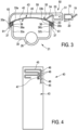
- a Fig.3 upwards and in the Fig.4 The heating side 43 shown carries the functional elements of the heating element 40.
- This heating side 43 is advantageously provided with a flat electrical insulation, for example a glass layer or a glass-like Layer.
- At least one heating conductor 45 is applied to it, here in a meandering shape, which is only partially shown.
- the heating conductor 45 is provided with contact fields 46 at its ends or ends there.
- a discrete temperature sensor 47 is provided on the heating side 43, for example designed as an SMD component.
- the temperature sensor 47 is connected to two contact fields 48. Further similar temperature sensors 47 can be provided, for example distributed in an area in which there is actually always water, so that a water temperature inside the heating chamber 28 can be detected.
- a temperature sensor 47 arranged in the upper area can detect a steam temperature.
- a surface temperature monitoring device (not shown in detail but known from the prior art) is advantageously provided, which can work by means of a temperature-dependent leakage current or a temperature-dependent leakage current.
- a temperature-dependent leakage current or a temperature-dependent leakage current.
- Such a temperature sensor can also have its own contact fields.
- the contact fields 46 and 48 are arranged along a line and at the same distance from a right-hand outer edge of the heating element carrier 41. This serves to improve electrical contact.
- an electrical connection device 50 is provided, which has a connection housing 51. This is arranged on a housing cover 59 as the upper housing part for the housing 22 of the steam generator 21 or is formed in one piece.
- Several plug connection lugs 53 are fixedly arranged in the connection housing 51, from which an elongated and thin contact arm 54 extends at their rear end. This is bent downwards and has a bent or hook-shaped contact end 55. This contact end 55 rests with the projection formed downwards on one of the contact fields 46 or 48. In this way, electrical contact can be made to the heating element 40, both for the high electrical power for heating operation and for small electrical power from temperature sensors or the like, by means of pressed-on contacts.
- a plug 18 is inserted into the connection housing 51, which has plug connection sockets 20 inside it that are connected to the connection cable 19.
- a plug connection can be secured by additional connecting means such as catches or the like.
- the lateral arrangement of the electrical connection or the electrical connection device 50 including the plug 18 results in a very flat design on the back of the steam oven 11. Furthermore, the plugging process for the electrical connection can be carried out safely and easily. Repair and maintenance work can also be carried out conveniently. The electrical connection does not increase the installation depth for the steam generator 21.
- connection housing 51 On the one hand, it is possible to mount the plug connection lugs 53 together with the contact arms 54 individually and firmly in the connection housing 51, for example by pressing them in or locking them in. Alternatively, they could also be injected directly.
- the electrical contact is then made to the contact fields 46 and 48 when the housing cover 59 is fastened. This fastening is carried out by means of the protruding locking hooks 61, which lock into place via locking projections 37, which are formed under the outer edge 35a and 35b.
- These locking connections are advantageously provided all around, particularly advantageously even at the narrow ends of the steam generator 21 next to the water inlet 24 and steam outlet 26.
- circumferential pressure projections 63 are provided on the housing cover 59 slightly above the locking hooks 61. These are located above the upper ends of the outer edges 35a and 35b and press the outer area of the heating element 40 against the seal 38 and in the direction of these outer edges 35. In this way, a firm, secure and permanently sealed arrangement of the heating element 40 on the heating chamber 28, whose cover it forms, is possible and guaranteed.
- the electrical connection to the heating element 40 is created when the housing cover 59 together with the electrical connection device 50 is pressed against the heating element 40 and the lower part of the housing 22 of the steam generator 22. It is provided that the heating element 40 is already arranged on the lower part of the housing 22, possibly pre-fixed. For this purpose, projections, possibly as small locking hooks or the like, could be formed on the outer edges 35a and 35b, which come from below and overlap the heating element 40 on its upper side 43 and hold it in its desired position or pre-fix it. If the housing cover 59 is now firmly locked into place with the contact types 54 on the lower part, these contact arms 54 rest with the free contact ends 55 on the contact fields 46 and 48.
- the individual plug connection lugs 53 are not arranged firmly in the connection housing 51 before the housing cover 59 is snapped on. Then groups of plug connection lugs, for example two groups, or alternatively all plug connection lugs, can be arranged in their own holding parts, which can then be positioned according to the plugging direction of the Fig.3 from the outside into the connection housing 51. They can be secured therein by means of snaps or the like.
- the contact ends 55 of the contact arms 54 come to rest on the contact fields 46 and 48 and thus establish the electrical contact.
- the connection housing 51 has a right-hand holding part 56a with several plug connection lugs 53 in an interior space 57a.
- connection housing 51 It is inserted into the connection housing 51 together, or alternatively separately, with a left-hand holding part 56b including further plug connection lugs (not shown here) via laterally protruding projections and receiving rails.
- the holding parts 56a and 56b are held in the connection housing 51 via a locking device (not shown in detail) from which a manually operable locking arm 58 protrudes upwards.
- the top of the housing cover 59 is provided with a honeycomb structure 60 as the ventilation openings mentioned above for the heating element 40. This simultaneously gives the housing cover 59 sufficient mechanical stability.
Landscapes
- Engineering & Computer Science (AREA)
- Mechanical Engineering (AREA)
- General Engineering & Computer Science (AREA)
- Physics & Mathematics (AREA)
- Life Sciences & Earth Sciences (AREA)
- Sustainable Development (AREA)
- Sustainable Energy (AREA)
- Thermal Sciences (AREA)
- Combustion & Propulsion (AREA)
- Chemical & Material Sciences (AREA)
- Food Science & Technology (AREA)
- Cookers (AREA)
- Resistance Heating (AREA)
Applications Claiming Priority (1)
| Application Number | Priority Date | Filing Date | Title |
|---|---|---|---|
| DE102022213368.4A DE102022213368A1 (de) | 2022-12-09 | 2022-12-09 | Vorrichtung zur Dampferzeugung und wasserführendes Haushaltsgerät mit einer solchen Vorrichtung |
Publications (2)
| Publication Number | Publication Date |
|---|---|
| EP4382811A1 true EP4382811A1 (fr) | 2024-06-12 |
| EP4382811B1 EP4382811B1 (fr) | 2025-10-29 |
Family
ID=89029557
Family Applications (1)
| Application Number | Title | Priority Date | Filing Date |
|---|---|---|---|
| EP23213070.8A Active EP4382811B1 (fr) | 2022-12-09 | 2023-11-29 | Dispositif de production de vapeur et appareil ménager à circulation d'eau doté d'un tel dispositif |
Country Status (5)
| Country | Link |
|---|---|
| US (1) | US20240191869A1 (fr) |
| EP (1) | EP4382811B1 (fr) |
| DE (1) | DE102022213368A1 (fr) |
| ES (1) | ES3058418T3 (fr) |
| PL (1) | PL4382811T3 (fr) |
Families Citing this family (1)
| Publication number | Priority date | Publication date | Assignee | Title |
|---|---|---|---|---|
| DE102023129498A1 (de) * | 2023-10-26 | 2024-10-31 | Miele & Cie. Kg | Dampferzeugereinrichtung und Verfahren zum Bereitstellen |
Citations (8)
| Publication number | Priority date | Publication date | Assignee | Title |
|---|---|---|---|---|
| WO2002012790A1 (fr) * | 2000-08-09 | 2002-02-14 | Rational Ag | Procede et dispositif de production de vapeur, en particulier pour un appareil de cuisson |
| EP1975517A2 (fr) | 2007-03-26 | 2008-10-01 | E.G.O. ELEKTRO-GERÄTEBAU GmbH | Procédé et appareil de cuisson à vapeur destinés au réglage de processus de cuisson dans un moufle de four |
| WO2008151798A2 (fr) * | 2007-06-14 | 2008-12-18 | E.G.O. Elektro-Gerätebau GmbH | Générateur de vapeur, dispositif de cuisson, procédé permettant de faire fonctionner ou de produire un générateur de vapeur, et procédé de refroidissement d'un dispositif de chauffe |
| DE102015218120A1 (de) | 2015-09-21 | 2017-03-23 | E.G.O. Elektro-Gerätebau GmbH | Heizeinrichtung zum Erhitzen von Wasser und Verfahren zum Betrieb einer solchen Heizeinrichtung |
| EP3278691A1 (fr) * | 2016-08-02 | 2018-02-07 | E.G.O. ELEKTRO-GERÄTEBAU GmbH | Évaporateur et appareil de cuisson comprenant un tel dispositif |
| EP3457027A2 (fr) * | 2017-09-19 | 2019-03-20 | E.G.O. ELEKTRO-GERÄTEBAU GmbH | Générateur de vapeur pour un appareil de cuisson à vapeur, appareil de cuisson à vapeur doté d'un tel générateur de vapeur et procédé de génération de la vapeur |
| DE102018217645A1 (de) | 2018-10-15 | 2020-04-16 | E.G.O. Elektro-Gerätebau GmbH | Verdampfereinrichtung und Elektrogerät mit einer Verdampfereinrichtung |
| EP3840528A1 (fr) | 2019-12-16 | 2021-06-23 | E.G.O. Elektro-Gerätebau GmbH | Procédé de fonctionnement d'un générateur de vapeur, générateur de vapeur et dispositif de cuisson doté d'un générateur de vapeur |
Family Cites Families (2)
| Publication number | Priority date | Publication date | Assignee | Title |
|---|---|---|---|---|
| DE102013205748A1 (de) | 2013-04-02 | 2014-10-02 | BSH Bosch und Siemens Hausgeräte GmbH | Dampferzeugungssystem für Haushalts-Gargerät |
| PL3096585T3 (pl) | 2015-05-18 | 2018-06-29 | E.G.O. Elektro-Gerätebau GmbH | Urządzenie grzejne do ogrzewania płynów i sposób eksploatacji takiego urządzenia grzejnego |
-
2022
- 2022-12-09 DE DE102022213368.4A patent/DE102022213368A1/de active Pending
-
2023
- 2023-11-28 US US18/520,838 patent/US20240191869A1/en active Pending
- 2023-11-29 PL PL23213070.8T patent/PL4382811T3/pl unknown
- 2023-11-29 ES ES23213070T patent/ES3058418T3/es active Active
- 2023-11-29 EP EP23213070.8A patent/EP4382811B1/fr active Active
Patent Citations (9)
| Publication number | Priority date | Publication date | Assignee | Title |
|---|---|---|---|---|
| WO2002012790A1 (fr) * | 2000-08-09 | 2002-02-14 | Rational Ag | Procede et dispositif de production de vapeur, en particulier pour un appareil de cuisson |
| EP1975517A2 (fr) | 2007-03-26 | 2008-10-01 | E.G.O. ELEKTRO-GERÄTEBAU GmbH | Procédé et appareil de cuisson à vapeur destinés au réglage de processus de cuisson dans un moufle de four |
| WO2008151798A2 (fr) * | 2007-06-14 | 2008-12-18 | E.G.O. Elektro-Gerätebau GmbH | Générateur de vapeur, dispositif de cuisson, procédé permettant de faire fonctionner ou de produire un générateur de vapeur, et procédé de refroidissement d'un dispositif de chauffe |
| DE102015218120A1 (de) | 2015-09-21 | 2017-03-23 | E.G.O. Elektro-Gerätebau GmbH | Heizeinrichtung zum Erhitzen von Wasser und Verfahren zum Betrieb einer solchen Heizeinrichtung |
| EP3278691A1 (fr) * | 2016-08-02 | 2018-02-07 | E.G.O. ELEKTRO-GERÄTEBAU GmbH | Évaporateur et appareil de cuisson comprenant un tel dispositif |
| EP3457027A2 (fr) * | 2017-09-19 | 2019-03-20 | E.G.O. ELEKTRO-GERÄTEBAU GmbH | Générateur de vapeur pour un appareil de cuisson à vapeur, appareil de cuisson à vapeur doté d'un tel générateur de vapeur et procédé de génération de la vapeur |
| DE102018217645A1 (de) | 2018-10-15 | 2020-04-16 | E.G.O. Elektro-Gerätebau GmbH | Verdampfereinrichtung und Elektrogerät mit einer Verdampfereinrichtung |
| EP3640537A1 (fr) * | 2018-10-15 | 2020-04-22 | E.G.O. Elektro-Gerätebau GmbH | Dispositif évaporateur et appareil électrique doté d'un dispositif évaporateur |
| EP3840528A1 (fr) | 2019-12-16 | 2021-06-23 | E.G.O. Elektro-Gerätebau GmbH | Procédé de fonctionnement d'un générateur de vapeur, générateur de vapeur et dispositif de cuisson doté d'un générateur de vapeur |
Also Published As
| Publication number | Publication date |
|---|---|
| EP4382811B1 (fr) | 2025-10-29 |
| ES3058418T3 (es) | 2026-03-10 |
| US20240191869A1 (en) | 2024-06-13 |
| DE102022213368A1 (de) | 2024-06-20 |
| PL4382811T3 (pl) | 2026-03-23 |
Similar Documents
| Publication | Publication Date | Title |
|---|---|---|
| EP2592982B1 (fr) | Dispositif de chauffe instantané dynamique | |
| DE102012202065B3 (de) | Pumpe und Verfahren zum Beheizen einer Pumpe | |
| EP2966935B1 (fr) | Appareil de cuisson et système de fixation | |
| DE102007058833A1 (de) | Heizeinrichtung für eine Waschmaschine, Waschmaschine mit einer Heizeinrichtung sowie Verfahren zum Betrieb einer Heizeinrichtung | |
| EP4382811B1 (fr) | Dispositif de production de vapeur et appareil ménager à circulation d'eau doté d'un tel dispositif | |
| EP2986769B1 (fr) | Dispositif de chauffage de surface pour le chauffage de l'eau dans un récipient à lessive, lave-linge et procédé de fabrication d'un dispositif de chauffage de surface | |
| EP0113923A2 (fr) | Plaque de cuisson électrique | |
| DE19847670A1 (de) | Wasserkessel für ein Elektro-Haushaltsgerät und Elektro-Haushaltsgerät mit einem solchen Wasserkessel | |
| EP0022878B1 (fr) | Dispositif de chauffage pour appareils chauffés électriquement | |
| DE29924784U1 (de) | Elektroherd mit mehreren Elektrokochplatten | |
| DE102009025729B3 (de) | Tränkevorrichtung für Nutztiere | |
| DE102019123761B4 (de) | Niederhalter zum Niederhalten eines Messsensors und Weiterleiten eines elektrischen Messsignals | |
| WO2019015886A1 (fr) | Élément chauffant et procédé de fabrication d'un élément chauffant | |
| EP3640537B1 (fr) | Dispositif évaporateur et appareil électrique doté d'un dispositif évaporateur | |
| EP4372274B1 (fr) | Dispositif de production de vapeur et appareil ménager équipé d'un tel dispositif | |
| DE102013216668A1 (de) | Verfahren und Vorrichtung zum Herstellen einer Heizwicklung auf einen metallischen Grundkörper | |
| DE19823506A1 (de) | Heizmanschette für Rohre | |
| DE102014215847A1 (de) | Einströmvorrichtung für einen zylindrischen Durchlauferhitzer mit Heizwendel | |
| DE102024115760A1 (de) | Vorrichtung zur Dampferzeugung und wasserführendes Haushaltsgerät mit einer solchen Vorrichtung | |
| DE8217975U1 (de) | Elektrisches haushaltsgeraet wie kaffee- oder teeautomat mit einer heizeinrichtung | |
| DE102005010044A1 (de) | Schutzkontaktverbindung | |
| DE3206460A1 (de) | Vorwaermegeraet fuer oel und verwendung des vorwaermegeraetes in einer heizungsanlage | |
| EP2056650A2 (fr) | Support pour un dispositif de chauffage électrique, dispositif de chauffage électrique et procédé de fabrication d'un dispositif de chauffage électrique | |
| DE1936112C3 (de) | Elektrischer Durchlauferhitzer | |
| EP4464231A1 (fr) | Dispositif de chauffage, pompe dotée d'un tel dispositif de chauffage et appareil ménager à circulation d'eau |
Legal Events
| Date | Code | Title | Description |
|---|---|---|---|
| PUAI | Public reference made under article 153(3) epc to a published international application that has entered the european phase |
Free format text: ORIGINAL CODE: 0009012 |
|
| STAA | Information on the status of an ep patent application or granted ep patent |
Free format text: STATUS: THE APPLICATION HAS BEEN PUBLISHED |
|
| AK | Designated contracting states |
Kind code of ref document: A1 Designated state(s): AL AT BE BG CH CY CZ DE DK EE ES FI FR GB GR HR HU IE IS IT LI LT LU LV MC ME MK MT NL NO PL PT RO RS SE SI SK SM TR |
|
| STAA | Information on the status of an ep patent application or granted ep patent |
Free format text: STATUS: REQUEST FOR EXAMINATION WAS MADE |
|
| 17P | Request for examination filed |
Effective date: 20241002 |
|
| RBV | Designated contracting states (corrected) |
Designated state(s): AL AT BE BG CH CY CZ DE DK EE ES FI FR GB GR HR HU IE IS IT LI LT LU LV MC ME MK MT NL NO PL PT RO RS SE SI SK SM TR |
|
| GRAP | Despatch of communication of intention to grant a patent |
Free format text: ORIGINAL CODE: EPIDOSNIGR1 |
|
| STAA | Information on the status of an ep patent application or granted ep patent |
Free format text: STATUS: GRANT OF PATENT IS INTENDED |
|
| INTG | Intention to grant announced |
Effective date: 20250730 |
|
| GRAS | Grant fee paid |
Free format text: ORIGINAL CODE: EPIDOSNIGR3 |
|
| GRAA | (expected) grant |
Free format text: ORIGINAL CODE: 0009210 |
|
| STAA | Information on the status of an ep patent application or granted ep patent |
Free format text: STATUS: THE PATENT HAS BEEN GRANTED |
|
| AK | Designated contracting states |
Kind code of ref document: B1 Designated state(s): AL AT BE BG CH CY CZ DE DK EE ES FI FR GB GR HR HU IE IS IT LI LT LU LV MC ME MK MT NL NO PL PT RO RS SE SI SK SM TR |
|
| REG | Reference to a national code |
Ref country code: CH Ref legal event code: F10 Free format text: ST27 STATUS EVENT CODE: U-0-0-F10-F00 (AS PROVIDED BY THE NATIONAL OFFICE) Effective date: 20251029 Ref country code: GB Ref legal event code: FG4D Free format text: NOT ENGLISH |
|
| REG | Reference to a national code |
Ref country code: IE Ref legal event code: FG4D Free format text: LANGUAGE OF EP DOCUMENT: GERMAN |
|
| REG | Reference to a national code |
Ref country code: DE Ref legal event code: R096 Ref document number: 502023002097 Country of ref document: DE |
|
| PGFP | Annual fee paid to national office [announced via postgrant information from national office to epo] |
Ref country code: DE Payment date: 20251126 Year of fee payment: 3 |
|
| PGFP | Annual fee paid to national office [announced via postgrant information from national office to epo] |
Ref country code: AT Payment date: 20260113 Year of fee payment: 3 |
|
| PGFP | Annual fee paid to national office [announced via postgrant information from national office to epo] |
Ref country code: FR Payment date: 20251201 Year of fee payment: 3 |
|
| PGFP | Annual fee paid to national office [announced via postgrant information from national office to epo] |
Ref country code: TR Payment date: 20251231 Year of fee payment: 3 |
|
| REG | Reference to a national code |
Ref country code: NL Ref legal event code: MP Effective date: 20251029 |
|
| REG | Reference to a national code |
Ref country code: ES Ref legal event code: FG2A Ref document number: 3058418 Country of ref document: ES Kind code of ref document: T3 Effective date: 20260310 |
|
| PGFP | Annual fee paid to national office [announced via postgrant information from national office to epo] |
Ref country code: ES Payment date: 20260116 Year of fee payment: 3 |
|
| REG | Reference to a national code |
Ref country code: LT Ref legal event code: MG9D |
|
| PG25 | Lapsed in a contracting state [announced via postgrant information from national office to epo] |
Ref country code: NO Free format text: LAPSE BECAUSE OF FAILURE TO SUBMIT A TRANSLATION OF THE DESCRIPTION OR TO PAY THE FEE WITHIN THE PRESCRIBED TIME-LIMIT Effective date: 20260129 |
|
| PG25 | Lapsed in a contracting state [announced via postgrant information from national office to epo] |
Ref country code: FI Free format text: LAPSE BECAUSE OF FAILURE TO SUBMIT A TRANSLATION OF THE DESCRIPTION OR TO PAY THE FEE WITHIN THE PRESCRIBED TIME-LIMIT Effective date: 20251029 Ref country code: HR Free format text: LAPSE BECAUSE OF FAILURE TO SUBMIT A TRANSLATION OF THE DESCRIPTION OR TO PAY THE FEE WITHIN THE PRESCRIBED TIME-LIMIT Effective date: 20251029 |
|
| PGFP | Annual fee paid to national office [announced via postgrant information from national office to epo] |
Ref country code: IT Payment date: 20251130 Year of fee payment: 3 |
|
| PG25 | Lapsed in a contracting state [announced via postgrant information from national office to epo] |
Ref country code: NL Free format text: LAPSE BECAUSE OF FAILURE TO SUBMIT A TRANSLATION OF THE DESCRIPTION OR TO PAY THE FEE WITHIN THE PRESCRIBED TIME-LIMIT Effective date: 20251029 |
|
| PG25 | Lapsed in a contracting state [announced via postgrant information from national office to epo] |
Ref country code: RS Free format text: LAPSE BECAUSE OF FAILURE TO SUBMIT A TRANSLATION OF THE DESCRIPTION OR TO PAY THE FEE WITHIN THE PRESCRIBED TIME-LIMIT Effective date: 20260129 |
|
| PG25 | Lapsed in a contracting state [announced via postgrant information from national office to epo] |
Ref country code: IS Free format text: LAPSE BECAUSE OF FAILURE TO SUBMIT A TRANSLATION OF THE DESCRIPTION OR TO PAY THE FEE WITHIN THE PRESCRIBED TIME-LIMIT Effective date: 20260228 |
|
| PG25 | Lapsed in a contracting state [announced via postgrant information from national office to epo] |
Ref country code: PT Free format text: LAPSE BECAUSE OF FAILURE TO SUBMIT A TRANSLATION OF THE DESCRIPTION OR TO PAY THE FEE WITHIN THE PRESCRIBED TIME-LIMIT Effective date: 20260302 |
|
| PGFP | Annual fee paid to national office [announced via postgrant information from national office to epo] |
Ref country code: PL Payment date: 20251030 Year of fee payment: 3 |
|
| PG25 | Lapsed in a contracting state [announced via postgrant information from national office to epo] |
Ref country code: LV Free format text: LAPSE BECAUSE OF FAILURE TO SUBMIT A TRANSLATION OF THE DESCRIPTION OR TO PAY THE FEE WITHIN THE PRESCRIBED TIME-LIMIT Effective date: 20251029 |
|
| PG25 | Lapsed in a contracting state [announced via postgrant information from national office to epo] |
Ref country code: BG Free format text: LAPSE BECAUSE OF FAILURE TO SUBMIT A TRANSLATION OF THE DESCRIPTION OR TO PAY THE FEE WITHIN THE PRESCRIBED TIME-LIMIT Effective date: 20251029 |