EP4383285A1 - Modul zur variation einer induktivität und hochfrequenzfilter mit einem solchen modul - Google Patents
Modul zur variation einer induktivität und hochfrequenzfilter mit einem solchen modul Download PDFInfo
- Publication number
- EP4383285A1 EP4383285A1 EP23214192.9A EP23214192A EP4383285A1 EP 4383285 A1 EP4383285 A1 EP 4383285A1 EP 23214192 A EP23214192 A EP 23214192A EP 4383285 A1 EP4383285 A1 EP 4383285A1
- Authority
- EP
- European Patent Office
- Prior art keywords
- inductance
- variation module
- electromagnet
- ferrite plate
- central opening
- Prior art date
- Legal status (The legal status is an assumption and is not a legal conclusion. Google has not performed a legal analysis and makes no representation as to the accuracy of the status listed.)
- Pending
Links
Images



Classifications
-
- H—ELECTRICITY
- H01—ELECTRIC ELEMENTS
- H01F—MAGNETS; INDUCTANCES; TRANSFORMERS; SELECTION OF MATERIALS FOR THEIR MAGNETIC PROPERTIES
- H01F21/00—Variable inductances or transformers of the signal type
- H01F21/02—Variable inductances or transformers of the signal type continuously variable, e.g. variometers
- H01F21/06—Variable inductances or transformers of the signal type continuously variable, e.g. variometers by movement of core or part of core relative to the windings as a whole
-
- H—ELECTRICITY
- H01—ELECTRIC ELEMENTS
- H01F—MAGNETS; INDUCTANCES; TRANSFORMERS; SELECTION OF MATERIALS FOR THEIR MAGNETIC PROPERTIES
- H01F29/00—Variable transformers or inductances not covered by group H01F21/00
- H01F29/14—Variable transformers or inductances not covered by group H01F21/00 with variable magnetic bias
- H01F29/146—Constructional details
-
- H—ELECTRICITY
- H01—ELECTRIC ELEMENTS
- H01F—MAGNETS; INDUCTANCES; TRANSFORMERS; SELECTION OF MATERIALS FOR THEIR MAGNETIC PROPERTIES
- H01F3/00—Cores, Yokes, or armatures
- H01F3/10—Composite arrangements of magnetic circuits
-
- H—ELECTRICITY
- H01—ELECTRIC ELEMENTS
- H01F—MAGNETS; INDUCTANCES; TRANSFORMERS; SELECTION OF MATERIALS FOR THEIR MAGNETIC PROPERTIES
- H01F3/00—Cores, Yokes, or armatures
- H01F3/10—Composite arrangements of magnetic circuits
- H01F3/14—Constrictions; Gaps, e.g. air-gaps
Definitions
- the present invention relates to an inductance variation module which can be applied to any radiocommunication product requiring the implementation of frequency tunable filters, in particular when these filters are positioned at the output of power stages.
- varicaps make it possible to continuously control a filter in a frequency band, for example in a frequency band between 30 and 43 MHz.
- varicaps do not support RF levels above a few mW.
- the varicaps used in the VHF and UHF bands are threatened with obsolescence.
- the present invention aims to remedy this need at least in part.
- the invention thus proposes to exploit the magnetic property of an assembly consisting of a magnetic circuit having an air gap in which we will place a low loss ferrite core.
- the main inductance is varied not by switching secondary inductances (for example with PIN diodes) but by varying the permeability of the ferrite.
- the configuration of such a variation module leads to a significant variation in the value of the inductance without an increase in magnetic losses, or even a reduction in magnetic losses, unlike more conventional configurations for which continuous magnetic fields and radio frequencies are collinear.
- the invention makes it possible to introduce an innovative approach in the production of broadband UHF electronic antenna.
- the central spaces of the electromagnet parts extend the central opening by forming an angle with said central opening of between 80 and 100 degrees.
- the central spaces of the electromagnet parts extend the central opening by forming an angle with said central opening of between 85 and 100 degrees.
- the central spaces of the electromagnet parts extend the central opening perpendicular to said central opening.
- the electromagnet is made of soft iron.
- a soft magnetic material with strong saturation magnetization such as soft iron, an iron-nickel alloy, an amorphous or nanocrystalline magnetic alloy. This allows the control power to be reduced.
- the ferrite plate is composed of a NiZnCuCo spinel ferrite.
- the permeability of such a ferrite is between 50 and 200 and it has low magnetic losses in the HF to VHF band.
- the ferrite plate has a thickness of between 0.1 and 2 mm.
- the ferrite plate has a thickness less than or equal to 1 mm.
- the module comprises means for keeping the electromagnet in contact with the ferrite plate.
- Another object relates to a radio frequency filter comprising at least one inductance variation module according to the invention.
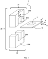
- the ferrite plate 10 extends mainly in a direction X and a direction Y and it has a thickness in a vertical direction Z perpendicular to the horizontal direction X and the direction Y.
- the ferrite plate 10 has a ratio between its thickness and its largest dimension which is less than 10%.
- the largest dimension corresponds to the length;
- the largest dimension corresponds to the side.
- Other forms can be considered.
- the plate should not be too thin, in order to avoid weakening the structure.
- This thickness is between 0.1 and 2 mm.
- the thickness of the plate 10 has a thickness of less than 1 mm.
- the thickness of the plate 10 is 0.5 mm.
- the ferrite plate 10 is composed of a NiZnCuCo ferrite.
- This ferrite plate 10 comprises a central opening 11 passing through said plate, so that said ferrite plate 10 has a torus shape.
- This central opening 11 has a generally rectangular shape.
- the electromagnet 20 frames the ferrite plate 10. It therefore comprises two electromagnet parts 21, 22.
- Each electromagnet part has a solid main body 210, 220 and an electromagnetic coil 211, 221 wound around the main body 210 , 220.
- Each electromagnetic coil 211, 221 is intended to be powered by a set current, having a frequency greater than 100 kHz (radio waves and higher, such as HF, VHF, UHF).
- Each main body 210, 220 has a U shape extending mainly in the direction Y and in a vertical direction Z'. The different U-shaped shapes define central spaces 212, 222 extending in the vertical direction Z'.
- the electromagnet parts 21, 22 are arranged on either side of the ferrite plate 10 in opposite at the level of the central opening 11, so that the central spaces 212, 222 of said electromagnet parts 21, 22 extend the central opening 11 substantially perpendicularly to said central opening 11.
- substantially perpendicularly we means that the vertical axis Z' associated with the electromagnet 20 makes an angle ⁇ with the horizontal axis X of the ferrite plate 10, between 80° and 100°.
- the planar shape of the ferrite plate 10 has a favorable demagnetizing effect in the plane of the plate, due to the shape anisotropy of the plate.
- the external contour of the ferrite plate has a shape such that it matches the overall contour of the section of the main bodies 210, 220 in the xy plane.
- the exterior contour of the ferrite plate 10 corresponds, in the main plane of extension of the plate (xy plane), to the section of the assembly formed by the main bodies 210, 220, at the level of their junction with the ferrite plate 10.
- the width of the plate (along the x axis) is identical to the width of each of the main bodies 210, 220.
- the length of the plate (along the y axis) is identical to the cumulative length of the main bodies 210, 220, and the central space (along the y axis).
- the ferrite plate 10 can be slightly smaller than the section of the main body 210, 220 in the xy plane, which makes it possible to better concentrate the static fields on the ferrite plate 10.
- the outer contour of the ferrite plate has dimensions, in the xy plane, which are smaller by at most 10% compared to the corresponding dimensions of the overall contour of the section of the main bodies (210, 220).
- the width of the plate (along the x axis) is less than 10% compared to the width of each of the main bodies 210, 220.
- the length of the plate (along the y axis) is less than at most 10% relative to the cumulative length of the main bodies 210, 220, and the central space (along the y axis).
- the surface area can be uniformly reduced all around the plate.
- the vertical axis Z' associated with the electromagnet 20 makes an angle ⁇ with the horizontal axis X of the ferrite plate 10, between 85° and 95°.
- the vertical axis Z' associated with the electromagnet 20 makes an angle ⁇ with the horizontal axis X of the ferrite plate 10, exactly equal to 90°.
- the vertical axis Z' and the vertical axis Z are the same.
- the electromagnet 20 is here made of soft iron.
- the holding means 30 make it possible to hold the electromagnet 20 against the ferrite plate 10.
- These holding means 30 are in the form of a tab which will act in compression on each main body 210, 220 to hold the parts of electromagnet 21, 22 against the ferrite plate 10.
- the objective is to saturate the parts of the NiZnCuCo ferrite using the set current applied in the DC circuit.
- the DC magnetic field produced by the soft iron circuit is perpendicular to the HF magnetic field created in the HF inductor.
- the permeability ⁇ of the NiZnCuCo ferrite in contact with the DC circuit will pass into a rotational regime which allows a more rapid variation of the permeability ⁇ of the ferrite with the applied magnetic field without increasing the magnetic losses.
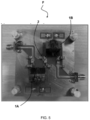
- the polarization circuit was produced by winding 50 turns of an enameled copper wire on each of the two parts of the previously machined U-shaped electromagnet 21, 22. Between these two U-shaped cores is inserted the HF core in the shape of a plate torus.
- a first series of measurements illustrated in Figure 3 was made by winding around twenty turns on each U-shaped core.
- the inductance and quality factor were measured as a function of the DC current injected into the windings.
- H DC Ni/Lm.
- B DC 2850 Gauss or 285 mT.
- a more precise measurement with the B(H) meter allows non-linear effects to be taken into account.
- FIG. 4 illustrates a variation of the HF inductance as a function of the applied DC current, we observe a variation of a factor of 3 for a current between 0 and 600 mA which corresponds to a control power of 220 mW. We obtain a factor of 5 for a current between 0 and 1200 mA and a power of 865 mW.
- the set current used to check the operation of the filter was positioned between 0 and 2A.
- the invention makes it possible to produce tunable power filters over a wide frequency band in a compact manner without the quality of the filter, in particular the losses, being affected.
- This invention can be implemented both on low power filters, a few tens of milliwatts, and on higher powers, from a few watts to 50 watts, or even 100 watts.
- the solution provided implements a physical phenomenon linking two materials with different magnetic properties and associated in an original way allowing perpendicularity of the magnetic fields.
Landscapes
- Engineering & Computer Science (AREA)
- Power Engineering (AREA)
- Chemical & Material Sciences (AREA)
- Composite Materials (AREA)
- Control Of Motors That Do Not Use Commutators (AREA)
- Coils Or Transformers For Communication (AREA)
- Filters And Equalizers (AREA)
Applications Claiming Priority (1)
| Application Number | Priority Date | Filing Date | Title |
|---|---|---|---|
| FR2212808A FR3142851B1 (fr) | 2022-12-06 | 2022-12-06 | Module de variation d'une inductance et filtre radiofréquence comportant un tel module |
Publications (1)
| Publication Number | Publication Date |
|---|---|
| EP4383285A1 true EP4383285A1 (de) | 2024-06-12 |
Family
ID=86468837
Family Applications (1)
| Application Number | Title | Priority Date | Filing Date |
|---|---|---|---|
| EP23214192.9A Pending EP4383285A1 (de) | 2022-12-06 | 2023-12-05 | Modul zur variation einer induktivität und hochfrequenzfilter mit einem solchen modul |
Country Status (3)
| Country | Link |
|---|---|
| EP (1) | EP4383285A1 (de) |
| FR (1) | FR3142851B1 (de) |
| SA (1) | SA123450973B1 (de) |
Citations (6)
| Publication number | Priority date | Publication date | Assignee | Title |
|---|---|---|---|---|
| US2513160A (en) * | 1945-10-02 | 1950-06-27 | Rca Corp | Transformer |
| EP0109096A1 (de) * | 1978-10-20 | 1984-05-23 | Hydro-Quebec | Anordnung mit variabler Induktivität |
| US20100254168A1 (en) * | 2009-03-31 | 2010-10-07 | Sriram Chandrasekaran | Magnetic Device Formed with U-Shaped Core Pieces and Power Converter Employing the Same |
| EP2357727A1 (de) * | 2010-02-12 | 2011-08-17 | EMIF Technology Limited | Filter gegen elektromagnetische Interferenz |
| US20110234354A1 (en) * | 2008-12-08 | 2011-09-29 | Sumida Corporation | Variable inductor |
| FR3059496A1 (fr) | 2016-11-29 | 2018-06-01 | Thales | Filtre accordable a inductance variable |
-
2022
- 2022-12-06 FR FR2212808A patent/FR3142851B1/fr active Active
-
2023
- 2023-12-05 EP EP23214192.9A patent/EP4383285A1/de active Pending
- 2023-12-05 SA SA123450973A patent/SA123450973B1/ar unknown
Patent Citations (6)
| Publication number | Priority date | Publication date | Assignee | Title |
|---|---|---|---|---|
| US2513160A (en) * | 1945-10-02 | 1950-06-27 | Rca Corp | Transformer |
| EP0109096A1 (de) * | 1978-10-20 | 1984-05-23 | Hydro-Quebec | Anordnung mit variabler Induktivität |
| US20110234354A1 (en) * | 2008-12-08 | 2011-09-29 | Sumida Corporation | Variable inductor |
| US20100254168A1 (en) * | 2009-03-31 | 2010-10-07 | Sriram Chandrasekaran | Magnetic Device Formed with U-Shaped Core Pieces and Power Converter Employing the Same |
| EP2357727A1 (de) * | 2010-02-12 | 2011-08-17 | EMIF Technology Limited | Filter gegen elektromagnetische Interferenz |
| FR3059496A1 (fr) | 2016-11-29 | 2018-06-01 | Thales | Filtre accordable a inductance variable |
Also Published As
| Publication number | Publication date |
|---|---|
| FR3142851B1 (fr) | 2025-01-03 |
| SA123450973B1 (ar) | 2025-05-20 |
| FR3142851A1 (fr) | 2024-06-07 |
Similar Documents
| Publication | Publication Date | Title |
|---|---|---|
| EP0771011B1 (de) | Gemischter Magnetkern | |
| EP2274753B1 (de) | Leistungswandler für hochfrequenzsignale | |
| EP3249705A1 (de) | Abstimmbarer magnonikkristallvorrichtung und filtrierungsverfahren | |
| FR2813987A1 (fr) | Microcomposant du type micro-inductance ou micro-transformateur | |
| EP2643886B1 (de) | Flachantenne mit erweiterter bandbreite | |
| FR2978596A1 (fr) | Transformateur du type symetrique-dissymetrique | |
| KR100402504B1 (ko) | 박막공진기들의모놀리식어레이및그제조방법과모놀리식박막공진기격자필터및그제조방법 | |
| FR2902933A1 (fr) | Combineur/diviseur de puissance | |
| EP1250729B1 (de) | Antenne mit anisotroper verbundstoff | |
| EP3692598B1 (de) | Antenne mit teilweise gesättigtem dispersivem ferromagnetischem substrat | |
| FR3142851A1 (fr) | Module de variation d'une inductance et filtre radiofréquence comportant un tel module | |
| EP0443481B1 (de) | Abstimmbarer Mikrowellenfilter | |
| EP0060174B1 (de) | Bandpassfilter mit dielektrischen Resonatoren | |
| FR2828337A1 (fr) | Circuit resonant hyperfrequence et filtre hyperfrequence accordable utilisant le circuit resonant | |
| FR2894078A1 (fr) | Combineur/diviseur de puissance integree | |
| US6816038B2 (en) | Magnetostatic wave device and disturbance wave eliminator | |
| EP3516736B1 (de) | Antenne mit gewundenen und miteinander verkoppelten ferromagnetischen stangen | |
| FR2610766A1 (fr) | Filtre hyperfrequence, accordable electroniquement | |
| JP4655257B2 (ja) | 2端子対アイソレータ | |
| FR2521786A2 (fr) | Filtre passe-bande a resonateurs dielectriques | |
| JP4823764B2 (ja) | 電磁ノイズをフィルタするための集積型マイクロエレクトロニクス構成要素、およびそれを備える無線周波数伝送回路 | |
| EP0082752B1 (de) | Breitbandiges nichtreziprokes Mikrowellengerät hoher Leistung und dessen Benutzung | |
| JP2011119905A (ja) | 周波数可変共振器 | |
| EP1178504A1 (de) | Mikrokomponente vom Typ Mikroinduktanz oder Mikrotransformator | |
| FR3154563A1 (fr) | Circuit électronique |
Legal Events
| Date | Code | Title | Description |
|---|---|---|---|
| PUAI | Public reference made under article 153(3) epc to a published international application that has entered the european phase |
Free format text: ORIGINAL CODE: 0009012 |
|
| STAA | Information on the status of an ep patent application or granted ep patent |
Free format text: STATUS: THE APPLICATION HAS BEEN PUBLISHED |
|
| AK | Designated contracting states |
Kind code of ref document: A1 Designated state(s): AL AT BE BG CH CY CZ DE DK EE ES FI FR GB GR HR HU IE IS IT LI LT LU LV MC ME MK MT NL NO PL PT RO RS SE SI SK SM TR |
|
| STAA | Information on the status of an ep patent application or granted ep patent |
Free format text: STATUS: REQUEST FOR EXAMINATION WAS MADE |
|
| 17P | Request for examination filed |
Effective date: 20241210 |