EP4383532A1 - Magnetische spannungswellengetriebevorrichtung - Google Patents
Magnetische spannungswellengetriebevorrichtung Download PDFInfo
- Publication number
- EP4383532A1 EP4383532A1 EP21952686.0A EP21952686A EP4383532A1 EP 4383532 A1 EP4383532 A1 EP 4383532A1 EP 21952686 A EP21952686 A EP 21952686A EP 4383532 A1 EP4383532 A1 EP 4383532A1
- Authority
- EP
- European Patent Office
- Prior art keywords
- rotor
- gear device
- stator
- wave gear
- strain wave
- Prior art date
- Legal status (The legal status is an assumption and is not a legal conclusion. Google has not performed a legal analysis and makes no representation as to the accuracy of the status listed.)
- Granted
Links
Images




Classifications
-
- H—ELECTRICITY
- H02—GENERATION; CONVERSION OR DISTRIBUTION OF ELECTRIC POWER
- H02K—DYNAMO-ELECTRIC MACHINES
- H02K49/00—Dynamo-electric clutches; Dynamo-electric brakes
- H02K49/10—Dynamo-electric clutches; Dynamo-electric brakes of the permanent-magnet type
- H02K49/102—Magnetic gearings, i.e. assembly of gears, linear or rotary, by which motion is magnetically transferred without physical contact
-
- H—ELECTRICITY
- H02—GENERATION; CONVERSION OR DISTRIBUTION OF ELECTRIC POWER
- H02K—DYNAMO-ELECTRIC MACHINES
- H02K1/00—Details of the magnetic circuit
- H02K1/06—Details of the magnetic circuit characterised by the shape, form or construction
- H02K1/12—Stationary parts of the magnetic circuit
- H02K1/17—Stator cores with permanent magnets
-
- H—ELECTRICITY
- H02—GENERATION; CONVERSION OR DISTRIBUTION OF ELECTRIC POWER
- H02K—DYNAMO-ELECTRIC MACHINES
- H02K1/00—Details of the magnetic circuit
- H02K1/06—Details of the magnetic circuit characterised by the shape, form or construction
- H02K1/22—Rotating parts of the magnetic circuit
- H02K1/223—Rotor cores with windings and permanent magnets
-
- H—ELECTRICITY
- H02—GENERATION; CONVERSION OR DISTRIBUTION OF ELECTRIC POWER
- H02K—DYNAMO-ELECTRIC MACHINES
- H02K1/00—Details of the magnetic circuit
- H02K1/06—Details of the magnetic circuit characterised by the shape, form or construction
- H02K1/22—Rotating parts of the magnetic circuit
- H02K1/27—Rotor cores with permanent magnets
- H02K1/2706—Inner rotors
- H02K1/272—Inner rotors the magnetisation axis of the magnets being perpendicular to the rotor axis
- H02K1/274—Inner rotors the magnetisation axis of the magnets being perpendicular to the rotor axis the rotor consisting of two or more circumferentially positioned magnets
- H02K1/2753—Inner rotors the magnetisation axis of the magnets being perpendicular to the rotor axis the rotor consisting of two or more circumferentially positioned magnets the rotor consisting of magnets or groups of magnets arranged with alternating polarity
- H02K1/276—Magnets embedded in the magnetic core, e.g. interior permanent magnets [IPM]
-
- H—ELECTRICITY
- H02—GENERATION; CONVERSION OR DISTRIBUTION OF ELECTRIC POWER
- H02K—DYNAMO-ELECTRIC MACHINES
- H02K1/00—Details of the magnetic circuit
- H02K1/06—Details of the magnetic circuit characterised by the shape, form or construction
- H02K1/22—Rotating parts of the magnetic circuit
- H02K1/27—Rotor cores with permanent magnets
- H02K1/2706—Inner rotors
- H02K1/272—Inner rotors the magnetisation axis of the magnets being perpendicular to the rotor axis
- H02K1/274—Inner rotors the magnetisation axis of the magnets being perpendicular to the rotor axis the rotor consisting of two or more circumferentially positioned magnets
- H02K1/2753—Inner rotors the magnetisation axis of the magnets being perpendicular to the rotor axis the rotor consisting of two or more circumferentially positioned magnets the rotor consisting of magnets or groups of magnets arranged with alternating polarity
- H02K1/278—Surface mounted magnets; Inset magnets
-
- H—ELECTRICITY
- H02—GENERATION; CONVERSION OR DISTRIBUTION OF ELECTRIC POWER
- H02K—DYNAMO-ELECTRIC MACHINES
- H02K1/00—Details of the magnetic circuit
- H02K1/06—Details of the magnetic circuit characterised by the shape, form or construction
- H02K1/22—Rotating parts of the magnetic circuit
- H02K1/28—Means for mounting or fastening rotating magnetic parts on to, or to, the rotor structures
- H02K1/30—Means for mounting or fastening rotating magnetic parts on to, or to, the rotor structures using intermediate parts, e.g. spiders
-
- H—ELECTRICITY
- H02—GENERATION; CONVERSION OR DISTRIBUTION OF ELECTRIC POWER
- H02K—DYNAMO-ELECTRIC MACHINES
- H02K16/00—Machines with more than one rotor or stator
- H02K16/02—Machines with one stator and two or more rotors
-
- H—ELECTRICITY
- H02—GENERATION; CONVERSION OR DISTRIBUTION OF ELECTRIC POWER
- H02K—DYNAMO-ELECTRIC MACHINES
- H02K21/00—Synchronous motors having permanent magnets; Synchronous generators having permanent magnets
- H02K21/12—Synchronous motors having permanent magnets; Synchronous generators having permanent magnets with stationary armatures and rotating magnets
- H02K21/14—Synchronous motors having permanent magnets; Synchronous generators having permanent magnets with stationary armatures and rotating magnets with magnets rotating within the armatures
- H02K21/16—Synchronous motors having permanent magnets; Synchronous generators having permanent magnets with stationary armatures and rotating magnets with magnets rotating within the armatures having annular armature cores with salient poles
-
- H—ELECTRICITY
- H02—GENERATION; CONVERSION OR DISTRIBUTION OF ELECTRIC POWER
- H02K—DYNAMO-ELECTRIC MACHINES
- H02K2213/00—Specific aspects, not otherwise provided for and not covered by codes H02K2201/00 - H02K2211/00
- H02K2213/12—Machines characterised by the modularity of some components
-
- Y—GENERAL TAGGING OF NEW TECHNOLOGICAL DEVELOPMENTS; GENERAL TAGGING OF CROSS-SECTIONAL TECHNOLOGIES SPANNING OVER SEVERAL SECTIONS OF THE IPC; TECHNICAL SUBJECTS COVERED BY FORMER USPC CROSS-REFERENCE ART COLLECTIONS [XRACs] AND DIGESTS
- Y02—TECHNOLOGIES OR APPLICATIONS FOR MITIGATION OR ADAPTATION AGAINST CLIMATE CHANGE
- Y02E—REDUCTION OF GREENHOUSE GAS [GHG] EMISSIONS, RELATED TO ENERGY GENERATION, TRANSMISSION OR DISTRIBUTION
- Y02E10/00—Energy generation through renewable energy sources
- Y02E10/70—Wind energy
- Y02E10/72—Wind turbines with rotation axis in wind direction
-
- Y—GENERAL TAGGING OF NEW TECHNOLOGICAL DEVELOPMENTS; GENERAL TAGGING OF CROSS-SECTIONAL TECHNOLOGIES SPANNING OVER SEVERAL SECTIONS OF THE IPC; TECHNICAL SUBJECTS COVERED BY FORMER USPC CROSS-REFERENCE ART COLLECTIONS [XRACs] AND DIGESTS
- Y02—TECHNOLOGIES OR APPLICATIONS FOR MITIGATION OR ADAPTATION AGAINST CLIMATE CHANGE
- Y02T—CLIMATE CHANGE MITIGATION TECHNOLOGIES RELATED TO TRANSPORTATION
- Y02T10/00—Road transport of goods or passengers
- Y02T10/60—Other road transportation technologies with climate change mitigation effect
- Y02T10/64—Electric machine technologies in electromobility
Definitions
- the present disclosure relates to a magnetic strain wave gear device.
- a magnetic strain wave gear device having a magnetic speed reducer and a rotating machine integrated with each other has been known as an electric generator for a wind power generation device.
- the magnetic strain wave gear device is composed of: a low-speed rotor; a high-speed rotor provided coaxially with the low-speed rotor; and a stator having stator windings and permanent magnets.
- the magnetic strain wave gear device can change the rotation speeds of the rotors in a contactless manner without using any mechanical transmission that experiences mechanical wear. Consequently, burden in maintenance against mechanical wear is mitigated in the magnetic strain wave gear device.
- speed change and power generation can be performed with the single device, whereby downsizing and space saving of a power generation system can be achieved.
- a magnetic strain wave gear device As a conventional magnetic strain wave gear device, a magnetic strain wave gear device has been disclosed in which a stator having a plurality of permanent magnets, a high-speed rotor having a plurality of rotor magnets, and a low-speed rotor having a plurality of magnetic pole pieces are concentrically arranged (see, for example, Patent Document 1).
- Patent Document 1 Japanese Laid-Open Patent Publication No. 2016-135014
- the plurality of permanent magnets of the stator are magnetized in a radial direction so as to form poles in the same direction.
- a high-speed rotor having magnetized rotor magnets incorporated therein needs to be inserted into the stator.
- the magnetic attraction forces serve as forces exerted with respect to the high-speed rotor in a direction perpendicular to the direction of the insertion. Consequently, the conventional magnetic strain wave gear device has a problem that it is difficult to accurately insert the high-speed rotor into the stator, whereby the efficiency of assembly work is low.
- the present disclosure has been made to solve the above problems, and an object of the present disclosure is to provide a magnetic strain wave gear device that makes it possible to achieve both improvement of the efficiency of assembly work and suppression of decrease in energy conversion efficiency.
- a magnetic strain wave gear device includes: a stator having a stator core provided with a plurality of slots in a circumferential direction, a stator winding disposed in each of the slots, and a stator magnet; a first rotor disposed radially inward of the stator with a gap interposed therebetween; and a second rotor disposed radially inward of the first rotor with a gap interposed therebetween, the second rotor being concentric with a rotation shaft of the first rotor.
- the second rotor includes a second rotor core provided with a plurality of rotor magnet insertion holes arrayed in the circumferential direction and a plurality of rotor magnets inserted into the plurality of respective rotor magnet insertion holes
- the first rotor includes a first rotor core having a cylindrical shape and a first rotor end plate fastening the first rotor core and the rotation shaft to each other and located outward of the second rotor in a direction of the rotation shaft
- the first rotor end plate has a rotor magnet passage hole through which the rotor magnets can be inserted into the rotor magnet insertion holes of the second rotor core from outside in the direction of the rotation shaft.
- the first rotor end plate has a rotor magnet passage hole through which the rotor magnets can be inserted into the rotor insertion holes of the second rotor core from outside in the direction of the rotation shaft. Consequently, the rotor magnets can be inserted into the rotor insertion holes of the second rotor core after the second rotor core is inserted to the inner circumferential side relative to the stator. Therefore, the magnetic strain wave gear device according to the present disclosure makes it possible to achieve both improvement of the efficiency of assembly work and suppression of decrease in energy conversion efficiency.
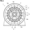
- FIG. 1 is a front view of a magnetic strain wave gear device according to embodiment 1.
- a magnetic strain wave gear device 1 includes a frame 2 having a cylindrical shape, a stator 3, a low-speed rotor 4, and a high-speed rotor 5.
- the stator 3 includes: a stator core 31 provided with a plurality of slots in a circumferential direction; stator windings 32 disposed in the slots; and stator magnets 33.
- the stator 3 is fixed to the frame 2 on the inner circumferential side relative to the frame 2.
- the low-speed rotor 4 has a low-speed rotor core having a cylindrical shape and disposed radially inward of the stator 3 with a gap interposed therebetween.
- the high-speed rotor 5 is disposed radially inward of the low-speed rotor core with a gap interposed therebetween and is concentric with a rotation shaft 41 of the low-speed rotor 4.
- the high-speed rotor 5 includes a high-speed rotor core 51 having a cylindrical shape and rotor magnets 52 arrayed in the circumferential direction.
- the low-speed rotor 4 includes a low-speed rotor end plate 42 fastening the low-speed rotor core and the rotation shaft 41 to each other and located outward of the high-speed rotor 5 in a direction of the rotation shaft 41.
- the low-speed rotor end plate 42 in the present embodiment is composed of a plurality of spokes 42a. The intervals between the plurality of spokes 42a are openings.
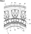
- FIG. 2 is a partial cross-sectional view of the magnetic strain wave gear device according to the present embodiment.
- the stator core 31 is composed of: a core back 31a having a cylindrical shape; and a plurality of teeth 31b protruding from the core back to the inner circumferential side so as to be arrayed in the circumferential direction.
- the intervals between the plurality of teeth 31b are spaces called slots, and the stator windings 32 are wound on the teeth 31b by utilizing the slots.
- the stator magnets 33 are fixed to both end portions of the teeth 31b on the inner circumferential side relative to the slots.
- a low-speed rotor core 43 is disposed radially inward of the stator 3 with a gap interposed therebetween.
- the high-speed rotor core 51 is disposed radially inward of the low-speed rotor core 43 with a gap interposed therebetween.
- the high-speed rotor core 51 has a plurality of rotor magnet insertion holes 51a formed on the outer circumferential side thereof so as to be arrayed in the circumferential direction.
- the plurality of rotor magnets 52 are inserted into the plurality of respective rotor magnet insertion holes 51a.
- the low-speed rotor end plate 42 has rotor magnet passage holes 42b through which the rotor magnets 52 can be inserted into the rotor magnet insertion holes 51a from outside in the direction of the rotation shaft 41, as shown in FIG. 1 .
- the low-speed rotor end plate 42 in the present embodiment is composed of the plurality of spokes, and thus, as shown in FIG. 1 , opening widths 10a and 10b between the plurality of spokes 42a of the low-speed rotor end plate 42 are irregular pitches.
- the opening width 10a of each interval that is larger out of the intervals between the spokes 42a is set to be larger than the width of each of the rotor magnet insertion holes 51a, whereby the opening between corresponding ones of the spokes 42a serves as a rotor magnet passage hole 42b.
- the stator windings 32 and the stator magnets 33 are attached to the stator core 31, to assemble the stator 3.
- This stator 3 is fixed to the inner circumferential side of the frame 2.
- the high-speed rotor core 51 is inserted, in the direction of the rotation shaft, to the inner circumferential side relative to the stator 3.
- the rotor magnets 52 have not been inserted into the rotor magnet insertion holes 51a of the high-speed rotor core 51.
- the low-speed rotor 4 is inserted, in the direction of the rotation shaft, into the gap between the stator 3 and the high-speed rotor 5.
- the rotor magnets 52 are caused to pass through the rotor magnet passage holes 42b of the low-speed rotor end plate 42 and are inserted into the rotor magnet insertion holes 51a of the high-speed rotor core 51.
- FIG. 3 is a perspective view of the magnetic strain wave gear device according to the present embodiment. As shown in FIG. 3 , each of the rotor magnets 52 is caused to pass through the corresponding rotor magnet passage hole 42b of the low-speed rotor end plate 42 and is inserted into the corresponding rotor magnet insertion hole 51a of the high-speed rotor core 51.
- the rotor magnets 52 have not been inserted into the rotor magnet insertion holes 51a of the high-speed rotor core 51 when the high-speed rotor core 51 is inserted to the inner circumferential side relative to the stator 3. Consequently, no magnetic attraction forces are exerted between the stator magnets 33 and the rotor magnets 52 when the high-speed rotor core 51 is inserted. As a result, when the high-speed rotor core 51 is inserted, no force is exerted in a direction perpendicular to the direction of the insertion. Therefore, the high-speed rotor core 51 can be accurately inserted into the stator 3.
- the conventional method in which the high-speed rotor core 51 is inserted to the inner circumferential side relative to the stator 3 in a state where the rotor magnets 52 have been attached to the high-speed rotor core 51 has a problem that it is impossible to achieve both improvement of the efficiency of assembly work and suppression of decrease in energy conversion efficiency.
- the rotor magnets can be caused to pass through the rotor magnet passage holes provided to the low-speed rotor end plate and can be inserted into the rotor magnet insertion holes of the high-speed rotor core after the high-speed rotor core to which the rotor magnets have not been attached is inserted to the inner circumferential side relative to the stator. Consequently, it is possible to achieve both improvement of the efficiency of assembly work and suppression of decrease in energy conversion efficiency.
- the high-speed rotor core 51 can be inserted to the inner circumferential side relative to the stator 3 such that the gap between the high-speed rotor core 51 and the stator 3 is narrowed. Consequently, an interval 10c (shown in FIG. 2 ) between each stator magnet 33 and the corresponding rotor magnet 52 can be narrowed, whereby the use amount of rotor magnets necessary for obtaining the same energy conversion efficiency as that in the conventional method can also be decreased.
- FIG. 4 is a front view of a magnetic strain wave gear device according to embodiment 2.
- the magnetic strain wave gear device 1 according to the present embodiment is the same as the magnetic strain wave gear device according to embodiment 1, except for the shape of the low-speed rotor end plate 42.
- the opening widths between the spokes of the low-speed rotor end plate are irregular pitches, and the opening width that is larger out of the opening widths between the spokes is set to be larger than the width of each of the rotor magnet insertion holes.
- a low-speed rotor end plate 42 is composed of two spokes 42a with the opening widths 10a between the spokes being regular pitches, and the openings between the two spokes serve as rotor magnet passage holes 42b.
- the opening widths 10a, between the spokes 42a, which are regular pitches are set to be larger than the width of each of the rotor magnet insertion holes 51a.
- the rotor magnets can be caused to pass through the rotor magnet passage holes 42b provided to the low-speed rotor end plate 42 and can be inserted into the rotor magnet insertion holes of the high-speed rotor core after the high-speed rotor core to which the rotor magnets have not been attached is inserted to the inner circumferential side relative to the stator, in the same manner as in embodiment 1. Consequently, it is possible to achieve both improvement of the efficiency of assembly work and suppression of decrease in energy conversion efficiency.
- the low-speed rotor end plate 42 is composed of the two spokes 42a arranged at regular pitches.
- the number of the spokes 42a of the low-speed rotor end plate 42 may be three or more as long as the opening widths, between the spokes, which are regular pitches are set to be larger than the width of each of the rotor magnet insertion holes.
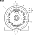
- FIG. 5 is a front view of a magnetic strain wave gear device according to embodiment 3.
- the magnetic strain wave gear device 1 according to the present embodiment is the same as the magnetic strain wave gear device according to embodiment 1, except for the shape of the low-speed rotor end plate 42.
- a low-speed rotor end plate 42 has a disc shape, and an opening having an opening width larger than the width of each of the rotor magnet insertion holes is formed in a portion of the low-speed rotor end plate 42.
- this opening serves as a rotor magnet passage hole 42b.
- the rotor magnets can be caused to pass through the rotor magnet passage hole 42b provided to the low-speed rotor end plate 42 and can be inserted into the rotor magnet insertion holes of the high-speed rotor core after the high-speed rotor core to which the rotor magnets have not been attached is inserted to the inner circumferential side relative to the stator, in the same manner as in embodiment 1. Consequently, it is possible to achieve both improvement of the efficiency of assembly work and suppression of decrease in energy conversion efficiency.
- the low-speed rotor end plate 42 has one rotor magnet passage hole 42b.
- another rotor magnet passage hole having the same shape may be formed at a position that is rotationally symmetric with the one rotor magnet passage hole 42b.
- the low-speed rotor end plate has a rotor magnet passage hole, and thus the rotor magnets can be inserted into the rotor magnet insertion holes of the high-speed rotor core after the high-speed rotor core is inserted to the inner circumferential side relative to the stator. Consequently, the intervals between the stator magnets and the rotor magnets can be narrowed. However, narrower intervals between the stator magnets and the rotor magnets lead to a greater loss arising from eddy current generated in the surfaces of the rotor magnets by influence of magnetic fluxes inflicted from the stator magnets.
- a magnetic strain wave gear device enables decrease of the eddy-current loss in the rotor magnets.
- FIG. 6 is a front view of the magnetic strain wave gear device according to the present embodiment.
- the magnetic strain wave gear device 1 according to the present embodiment is the same as the magnetic strain wave gear device according to embodiment 1, except for the rotor magnets 52.
- FIG. 7 is a configuration diagram of a rotor magnet in the present embodiment.
- the rotor magnet 52 in the present embodiment is composed of a base 52a and a plurality of division magnet pieces 52b fixed to the outer circumferential side of the base 52a.
- the base 52a is made from, for example, a magnetic material such as iron.
- the plurality of division magnet pieces 52b are arrayed in the circumferential direction and an axial direction of the high-speed rotor 5 and fixed to the base 52a. Gaps are present between the division magnet pieces 52b.
- the rotor magnet 52 composed of the base 52a and the plurality of division magnet pieces 52b fixed to the outer circumferential side of the base 52a is referred to as a modularized rotor magnet.
- each of the rotor magnets 52 includes the division magnet pieces 52b, and thus the apparent electric conductivity of the surface of the rotor magnet 52 through which eddy current flows decreases. Consequently, eddy current becomes less likely to flow, whereby the eddy-current loss in the rotor magnet 52 can be decreased.
- FIG. 8 is a partial cross-sectional view of the magnetic strain wave gear device according to the present embodiment.
- the interval 10c between the stator magnet 33 and the rotor magnet 52 can be further narrowed as compared to a case where the rotor magnet is not modularized, under the designing condition that the eddy-current loss is set to be not larger than a certain value. Consequently, the use amount of rotor magnets necessary for obtaining the same energy conversion efficiency can be further decreased.
- FIG. 9 is a perspective view of the magnetic strain wave gear device according to the present embodiment.
- the modularized rotor magnet 52 is caused to pass through the corresponding rotor magnet passage hole 42b of the low-speed rotor end plate 42 and is inserted into the corresponding rotor magnet insertion hole 51a of the high-speed rotor core 51.
- the magnetic strain wave gear device 1 which is thus configured, the rotor magnets 52 have not been inserted into the rotor magnet insertion holes 51a of the high-speed rotor core 51 when the high-speed rotor core 51 is inserted to the inner circumferential side relative to the stator 3. Consequently, no magnetic attraction forces are exerted between the stator magnets 33 and the rotor magnets 52 when the high-speed rotor core 51 is inserted. As a result, when the high-speed rotor core 51 is inserted, no force is exerted in the direction perpendicular to the direction of the insertion. Therefore, the high-speed rotor core 51 can be accurately inserted into the stator 3. Consequently, the magnetic strain wave gear device according to the present embodiment makes it possible to achieve both improvement of the efficiency of assembly work and suppression of decrease in energy conversion efficiency, in the same manner as in embodiment 1.
- each of the rotor magnets 52 includes the division magnet pieces 52b, whereby the eddy-current loss in the rotor magnet 52 can be decreased.
- FIG. 10 is a front view of a magnetic strain wave gear device according to embodiment 5.
- the magnetic strain wave gear device 1 according to the present embodiment is the same as the magnetic strain wave gear device according to embodiment 4, except for the shape of the low-speed rotor end plate 42.
- each of the rotor magnets 52 is modularized in the same manner as in embodiment 4.
- a low-speed rotor end plate 42 in the present embodiment is composed of two spokes with the opening widths 10a between the spokes 42a being regular pitches, and the spaces between the two spokes serve as rotor magnet passage holes 42b.
- the opening widths 10a, between the spokes, which are regular pitches are set to be larger than the width of each of the rotor magnet insertion holes 51a.
- the rotor magnets 52 can be caused to pass through the rotor magnet passage holes 42b provided to the low-speed rotor end plate 42 and can be inserted into the rotor magnet insertion holes of the high-speed rotor core after the high-speed rotor core to which the rotor magnets have not been attached is inserted to the inner circumferential side relative to the stator, in the same manner as in embodiment 2. Consequently, it is possible to achieve both improvement of the efficiency of assembly work and suppression of decrease in energy conversion efficiency.
- each of the rotor magnets 52 is modularized in the same manner as in embodiment 4, whereby the eddy-current loss in the rotor magnet 52 can be decreased.
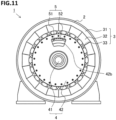
- FIG. 11 is a front view of a magnetic strain wave gear device according to embodiment 6.
- the magnetic strain wave gear device 1 according to the present embodiment is the same as the magnetic strain wave gear device according to embodiment 4, except for the shape of the low-speed rotor end plate 42.
- each of the rotor magnets 52 is modularized in the same manner as in embodiment 4.
- a low-speed rotor end plate 42 in the present embodiment has a plate shape, and an opening having an opening width larger than the width of each of the rotor magnet insertion holes is formed in a portion of the low-speed rotor end plate 42.
- this opening serves as a rotor magnet passage hole 42b.
- the rotor magnets can be caused to pass through the rotor magnet passage hole 42b provided to the low-speed rotor end plate 42 and can be inserted into the rotor magnet insertion holes of the high-speed rotor core after the high-speed rotor core to which the rotor magnets have not been attached is inserted to the inner circumferential side relative to the stator, in the same manner as in embodiment 3. Consequently, it is possible to achieve both improvement of the efficiency of assembly work and suppression of decrease in energy conversion efficiency.
- each of the rotor magnets 52 is modularized in the same manner as in embodiment 4, whereby the eddy-current loss in the rotor magnet 52 can be decreased.
- the rotor magnets 52 are modularized. Thus, when the rotor magnets 52 are caused to pass through the rotor magnet passage holes 42b and are inserted into the rotor magnet insertion holes 51a of the high-speed rotor core, the division magnet pieces 52b are not separated, whereby the rotor magnets 52 are easily inserted.
- Each of the modularized rotor magnets 52 does not have to be provided with any base 52a as long as the division magnet piece 52b can be inserted into the corresponding rotor magnet insertion hole 51a.
- the division magnet pieces 52b are arrayed in the circumferential direction and the axial direction of the high-speed rotor 5.
- the division magnet pieces 52b may be arrayed in at least one of the circumferential direction and the axial direction of the high-speed rotor 5.
Landscapes
- Engineering & Computer Science (AREA)
- Power Engineering (AREA)
- Permanent Field Magnets Of Synchronous Machinery (AREA)
- Connection Of Motors, Electrical Generators, Mechanical Devices, And The Like (AREA)
- Permanent Magnet Type Synchronous Machine (AREA)
Applications Claiming Priority (1)
| Application Number | Priority Date | Filing Date | Title |
|---|---|---|---|
| PCT/JP2021/028562 WO2023012855A1 (ja) | 2021-08-02 | 2021-08-02 | 磁気波動歯車装置 |
Publications (3)
| Publication Number | Publication Date |
|---|---|
| EP4383532A1 true EP4383532A1 (de) | 2024-06-12 |
| EP4383532A4 EP4383532A4 (de) | 2024-10-23 |
| EP4383532B1 EP4383532B1 (de) | 2025-10-22 |
Family
ID=85155404
Family Applications (1)
| Application Number | Title | Priority Date | Filing Date |
|---|---|---|---|
| EP21952686.0A Active EP4383532B1 (de) | 2021-08-02 | 2021-08-02 | Magnetische spannungswellengetriebevorrichtung |
Country Status (6)
| Country | Link |
|---|---|
| US (1) | US12451789B2 (de) |
| EP (1) | EP4383532B1 (de) |
| JP (1) | JP7527493B2 (de) |
| CN (1) | CN117652081A (de) |
| DK (1) | DK4383532T3 (de) |
| WO (1) | WO2023012855A1 (de) |
Families Citing this family (1)
| Publication number | Priority date | Publication date | Assignee | Title |
|---|---|---|---|---|
| JP7361344B2 (ja) * | 2019-02-26 | 2023-10-16 | パナソニックIpマネジメント株式会社 | 磁気ギアードモータ |
Family Cites Families (10)
| Publication number | Priority date | Publication date | Assignee | Title |
|---|---|---|---|---|
| JP2004075353A (ja) | 2002-08-21 | 2004-03-11 | Mitsubishi Electric Corp | エレベータ用巻上機 |
| JP2007129839A (ja) | 2005-11-04 | 2007-05-24 | Fuji Electric Fa Components & Systems Co Ltd | ブレーキ内蔵形回転電機 |
| JP4859751B2 (ja) * | 2007-05-15 | 2012-01-25 | 本田技研工業株式会社 | 回転電機 |
| GB2468888B (en) * | 2009-03-26 | 2013-11-06 | Magnomatics Ltd | Marine propulsion device with an electrical machine having integral magnetic gearing |
| EP2572440B1 (de) * | 2010-05-17 | 2021-10-20 | Magnomatics Limited | Magnetisches getriebe |
| JP5435805B2 (ja) * | 2010-08-11 | 2014-03-05 | 本田技研工業株式会社 | 多重ロータモータ |
| JP5350438B2 (ja) * | 2011-06-29 | 2013-11-27 | 株式会社日立製作所 | 磁気式歯車機構 |
| JP6403329B2 (ja) | 2015-01-20 | 2018-10-10 | 株式会社Ihi | 磁気波動歯車装置 |
| EP3261238B1 (de) * | 2016-06-23 | 2020-08-12 | Goodrich Actuation Systems Limited | Magnetgetriebe |
| CN116997736A (zh) * | 2021-03-12 | 2023-11-03 | 三菱电机株式会社 | 磁通调制型磁齿轮 |
-
2021
- 2021-08-02 US US18/551,711 patent/US12451789B2/en active Active
- 2021-08-02 EP EP21952686.0A patent/EP4383532B1/de active Active
- 2021-08-02 WO PCT/JP2021/028562 patent/WO2023012855A1/ja not_active Ceased
- 2021-08-02 CN CN202180100810.2A patent/CN117652081A/zh not_active Withdrawn
- 2021-08-02 JP JP2023539228A patent/JP7527493B2/ja active Active
- 2021-08-02 DK DK21952686.0T patent/DK4383532T3/da active
Also Published As
| Publication number | Publication date |
|---|---|
| DK4383532T3 (da) | 2025-12-01 |
| EP4383532A4 (de) | 2024-10-23 |
| WO2023012855A1 (ja) | 2023-02-09 |
| CN117652081A (zh) | 2024-03-05 |
| JPWO2023012855A1 (de) | 2023-02-09 |
| US12451789B2 (en) | 2025-10-21 |
| US20240097547A1 (en) | 2024-03-21 |
| EP4383532B1 (de) | 2025-10-22 |
| JP7527493B2 (ja) | 2024-08-02 |
Similar Documents
| Publication | Publication Date | Title |
|---|---|---|
| US12289016B2 (en) | Rotating electric machine and stator manufacturing method | |
| EP1990895B1 (de) | Belastungsverteilende Permamentmagnet-Rotorgeometrie für elektrische Maschinen | |
| EP1892814A1 (de) | Motor des typs mit doppelrotor | |
| EP3068021A1 (de) | Elektrische drehmaschine mit einem eingebauten permanentmagneten | |
| EP2110933A1 (de) | Elektrischer motor, rotorstruktur und magnetische maschine | |
| JP2015033329A (ja) | トルクリップルが低減されたスポーク永久磁石機械およびその製造方法 | |
| EP3022829B1 (de) | Laufer für einen elektromotor | |
| EP4096070A1 (de) | Stator und rotierende elektrische maschine damit | |
| AU2016366624A1 (en) | An electric motor | |
| EP4138285A1 (de) | Elektrische drehmaschine | |
| JP2014045630A (ja) | 回転電機 | |
| EP4096061A1 (de) | Stator und rotierende elektrische maschine damit | |
| EP4383532B1 (de) | Magnetische spannungswellengetriebevorrichtung | |
| US11387697B2 (en) | Rotary electric machine | |
| CN102790502A (zh) | 永磁同步电机 | |
| EP2919369A1 (de) | Elektromagnetischer generator | |
| EP4096062A1 (de) | Stator und rotierende elektrische maschine damit | |
| EP3494628B1 (de) | Rotor für eine bürstenlose elektrische maschine und bürstenlose elektrische maschine | |
| WO2019102580A1 (ja) | 永久磁石式回転電機 | |
| EP4299951A1 (de) | Magnetische zahnraddrehmaschine, stromerzeugungssystem und magnetpolstückrotor | |
| EP4138286A1 (de) | Magnetgetriebemotor | |
| WO2018123830A1 (ja) | 回転電機 | |
| KR100373427B1 (ko) | 자석식 전동기 및 발전기 | |
| EP4443708A1 (de) | Rotor und magnetische wellengetriebevorrichtung | |
| CN114402505B (zh) | 转子、电机和用于减小转子的不平衡的方法 |
Legal Events
| Date | Code | Title | Description |
|---|---|---|---|
| STAA | Information on the status of an ep patent application or granted ep patent |
Free format text: STATUS: THE INTERNATIONAL PUBLICATION HAS BEEN MADE |
|
| PUAI | Public reference made under article 153(3) epc to a published international application that has entered the european phase |
Free format text: ORIGINAL CODE: 0009012 |
|
| STAA | Information on the status of an ep patent application or granted ep patent |
Free format text: STATUS: REQUEST FOR EXAMINATION WAS MADE |
|
| 17P | Request for examination filed |
Effective date: 20230918 |
|
| AK | Designated contracting states |
Kind code of ref document: A1 Designated state(s): AL AT BE BG CH CY CZ DE DK EE ES FI FR GB GR HR HU IE IS IT LI LT LU LV MC MK MT NL NO PL PT RO RS SE SI SK SM TR |
|
| A4 | Supplementary search report drawn up and despatched |
Effective date: 20240924 |
|
| RIC1 | Information provided on ipc code assigned before grant |
Ipc: H02K 1/276 20220101ALI20240918BHEP Ipc: H02K 1/17 20060101ALI20240918BHEP Ipc: H02K 1/30 20060101ALI20240918BHEP Ipc: H02K 16/02 20060101AFI20240918BHEP |
|
| DAV | Request for validation of the european patent (deleted) | ||
| DAX | Request for extension of the european patent (deleted) | ||
| GRAP | Despatch of communication of intention to grant a patent |
Free format text: ORIGINAL CODE: EPIDOSNIGR1 |
|
| STAA | Information on the status of an ep patent application or granted ep patent |
Free format text: STATUS: GRANT OF PATENT IS INTENDED |
|
| INTG | Intention to grant announced |
Effective date: 20250314 |
|
| GRAJ | Information related to disapproval of communication of intention to grant by the applicant or resumption of examination proceedings by the epo deleted |
Free format text: ORIGINAL CODE: EPIDOSDIGR1 |
|
| STAA | Information on the status of an ep patent application or granted ep patent |
Free format text: STATUS: REQUEST FOR EXAMINATION WAS MADE |
|
| GRAP | Despatch of communication of intention to grant a patent |
Free format text: ORIGINAL CODE: EPIDOSNIGR1 |
|
| STAA | Information on the status of an ep patent application or granted ep patent |
Free format text: STATUS: GRANT OF PATENT IS INTENDED |
|
| INTC | Intention to grant announced (deleted) | ||
| INTG | Intention to grant announced |
Effective date: 20250516 |
|
| GRAS | Grant fee paid |
Free format text: ORIGINAL CODE: EPIDOSNIGR3 |
|
| GRAA | (expected) grant |
Free format text: ORIGINAL CODE: 0009210 |
|
| STAA | Information on the status of an ep patent application or granted ep patent |
Free format text: STATUS: THE PATENT HAS BEEN GRANTED |
|
| AK | Designated contracting states |
Kind code of ref document: B1 Designated state(s): AL AT BE BG CH CY CZ DE DK EE ES FI FR GB GR HR HU IE IS IT LI LT LU LV MC MK MT NL NO PL PT RO RS SE SI SK SM TR |
|
| REG | Reference to a national code |
Ref country code: CH Ref legal event code: F10 Free format text: ST27 STATUS EVENT CODE: U-0-0-F10-F00 (AS PROVIDED BY THE NATIONAL OFFICE) Effective date: 20251022 Ref country code: GB Ref legal event code: FG4D |
|
| REG | Reference to a national code |
Ref country code: DE Ref legal event code: R096 Ref document number: 602021041083 Country of ref document: DE |
|
| REG | Reference to a national code |
Ref country code: IE Ref legal event code: FG4D |
|
| REG | Reference to a national code |
Ref country code: DK Ref legal event code: T3 Effective date: 20251125 |
|
| REG | Reference to a national code |
Ref country code: NL Ref legal event code: MP Effective date: 20251022 |
|
| PG25 | Lapsed in a contracting state [announced via postgrant information from national office to epo] |
Ref country code: NL Free format text: LAPSE BECAUSE OF FAILURE TO SUBMIT A TRANSLATION OF THE DESCRIPTION OR TO PAY THE FEE WITHIN THE PRESCRIBED TIME-LIMIT Effective date: 20251022 |
|
| PG25 | Lapsed in a contracting state [announced via postgrant information from national office to epo] |
Ref country code: ES Free format text: LAPSE BECAUSE OF FAILURE TO SUBMIT A TRANSLATION OF THE DESCRIPTION OR TO PAY THE FEE WITHIN THE PRESCRIBED TIME-LIMIT Effective date: 20251022 |
|
| REG | Reference to a national code |
Ref country code: LT Ref legal event code: MG9D |
|
| PG25 | Lapsed in a contracting state [announced via postgrant information from national office to epo] |
Ref country code: NO Free format text: LAPSE BECAUSE OF FAILURE TO SUBMIT A TRANSLATION OF THE DESCRIPTION OR TO PAY THE FEE WITHIN THE PRESCRIBED TIME-LIMIT Effective date: 20260122 |
|
| PG25 | Lapsed in a contracting state [announced via postgrant information from national office to epo] |
Ref country code: HR Free format text: LAPSE BECAUSE OF FAILURE TO SUBMIT A TRANSLATION OF THE DESCRIPTION OR TO PAY THE FEE WITHIN THE PRESCRIBED TIME-LIMIT Effective date: 20251022 Ref country code: AT Free format text: LAPSE BECAUSE OF FAILURE TO SUBMIT A TRANSLATION OF THE DESCRIPTION OR TO PAY THE FEE WITHIN THE PRESCRIBED TIME-LIMIT Effective date: 20251022 Ref country code: FI Free format text: LAPSE BECAUSE OF FAILURE TO SUBMIT A TRANSLATION OF THE DESCRIPTION OR TO PAY THE FEE WITHIN THE PRESCRIBED TIME-LIMIT Effective date: 20251022 |
|
| REG | Reference to a national code |
Ref country code: AT Ref legal event code: MK05 Ref document number: 1850102 Country of ref document: AT Kind code of ref document: T Effective date: 20251022 |
|
| PG25 | Lapsed in a contracting state [announced via postgrant information from national office to epo] |
Ref country code: RS Free format text: LAPSE BECAUSE OF FAILURE TO SUBMIT A TRANSLATION OF THE DESCRIPTION OR TO PAY THE FEE WITHIN THE PRESCRIBED TIME-LIMIT Effective date: 20260122 |
|
| PG25 | Lapsed in a contracting state [announced via postgrant information from national office to epo] |
Ref country code: IS Free format text: LAPSE BECAUSE OF FAILURE TO SUBMIT A TRANSLATION OF THE DESCRIPTION OR TO PAY THE FEE WITHIN THE PRESCRIBED TIME-LIMIT Effective date: 20260222 |
|
| PG25 | Lapsed in a contracting state [announced via postgrant information from national office to epo] |
Ref country code: PT Free format text: LAPSE BECAUSE OF FAILURE TO SUBMIT A TRANSLATION OF THE DESCRIPTION OR TO PAY THE FEE WITHIN THE PRESCRIBED TIME-LIMIT Effective date: 20260223 |
|
| PG25 | Lapsed in a contracting state [announced via postgrant information from national office to epo] |
Ref country code: PL Free format text: LAPSE BECAUSE OF FAILURE TO SUBMIT A TRANSLATION OF THE DESCRIPTION OR TO PAY THE FEE WITHIN THE PRESCRIBED TIME-LIMIT Effective date: 20251022 |
|
| PG25 | Lapsed in a contracting state [announced via postgrant information from national office to epo] |
Ref country code: LV Free format text: LAPSE BECAUSE OF FAILURE TO SUBMIT A TRANSLATION OF THE DESCRIPTION OR TO PAY THE FEE WITHIN THE PRESCRIBED TIME-LIMIT Effective date: 20251022 |