EP4385367A1 - Elastic module balance cushion, elastic cushion, and furniture - Google Patents
Elastic module balance cushion, elastic cushion, and furniture Download PDFInfo
- Publication number
- EP4385367A1 EP4385367A1 EP22855326.9A EP22855326A EP4385367A1 EP 4385367 A1 EP4385367 A1 EP 4385367A1 EP 22855326 A EP22855326 A EP 22855326A EP 4385367 A1 EP4385367 A1 EP 4385367A1
- Authority
- EP
- European Patent Office
- Prior art keywords
- elastic
- pad
- limit
- base plate
- limit bosses
- Prior art date
- Legal status (The legal status is an assumption and is not a legal conclusion. Google has not performed a legal analysis and makes no representation as to the accuracy of the status listed.)
- Pending
Links
Images


Classifications
-
- A—HUMAN NECESSITIES
- A47—FURNITURE; DOMESTIC ARTICLES OR APPLIANCES; COFFEE MILLS; SPICE MILLS; SUCTION CLEANERS IN GENERAL
- A47C—CHAIRS; SOFAS; BEDS
- A47C27/00—Spring, stuffed or fluid mattresses or cushions specially adapted for chairs, beds or sofas
- A47C27/04—Spring, stuffed or fluid mattresses or cushions specially adapted for chairs, beds or sofas with spring inlays
- A47C27/06—Spring inlays or spring units therefor
- A47C27/07—Attaching, or interconnecting of, springs in spring inlays
-
- A—HUMAN NECESSITIES
- A47—FURNITURE; DOMESTIC ARTICLES OR APPLIANCES; COFFEE MILLS; SPICE MILLS; SUCTION CLEANERS IN GENERAL
- A47C—CHAIRS; SOFAS; BEDS
- A47C23/00—Spring mattresses with rigid frame or forming part of the bedstead, e.g. box springs; Divan bases; Slatted bed bases
- A47C23/002—Spring mattresses with rigid frame or forming part of the bedstead, e.g. box springs; Divan bases; Slatted bed bases with separate resilient support elements, e.g. elastomeric springs arranged in a two-dimensional matrix pattern
-
- A—HUMAN NECESSITIES
- A47—FURNITURE; DOMESTIC ARTICLES OR APPLIANCES; COFFEE MILLS; SPICE MILLS; SUCTION CLEANERS IN GENERAL
- A47C—CHAIRS; SOFAS; BEDS
- A47C27/00—Spring, stuffed or fluid mattresses or cushions specially adapted for chairs, beds or sofas
- A47C27/04—Spring, stuffed or fluid mattresses or cushions specially adapted for chairs, beds or sofas with spring inlays
- A47C27/06—Spring inlays or spring units therefor
- A47C27/063—Spring inlays or spring units therefor wrapped or otherwise protected
-
- A—HUMAN NECESSITIES
- A47—FURNITURE; DOMESTIC ARTICLES OR APPLIANCES; COFFEE MILLS; SPICE MILLS; SUCTION CLEANERS IN GENERAL
- A47C—CHAIRS; SOFAS; BEDS
- A47C27/00—Spring, stuffed or fluid mattresses or cushions specially adapted for chairs, beds or sofas
- A47C27/04—Spring, stuffed or fluid mattresses or cushions specially adapted for chairs, beds or sofas with spring inlays
- A47C27/06—Spring inlays or spring units therefor
- A47C27/065—Spring inlays or spring units therefor of special shape
Definitions
- the present disclosure relates to the field of furniture, and particularly to a balancing pad in use with elastic modules, and an elastic pad and a furniture comprising the same.
- Furniture such as beds is an indispensable object in people's life. Most of the conventional large-sized furniture is not easily disassembled or not easily restored after disassembly. However, with the development of modern life, it is required furniture especially such as beds are able to be disassembled and assembled more and more frequently to meet the needs of population migration and field leisure. During transportation, it is very difficult to disassemble and assemble the beds, resulting in that the beds which are still in use are sometimes discarded to reduce the transportation burden.
- a bed normally consists of a bed frame, an elastic pad, and an outer cover.
- a conventional elastic pad is usually one-piece, non-detachable and integral pad formed from a plurality of superimposed layers and springs.
- the integral pad is large in size and is not easy to be disassembled and stored.
- a conventional separately-pocketed spring mattress is intended to avoid two or more people lying in bed at the same time from affecting each other (e.g., if a weight difference between individuals is relatively large, one of them will inevitably affect the other when turning over or moving the body).
- each spring is individually packaged in a pocket or sleeve made of a nonwoven fabric or other material.
- the spring pockets are arranged in a pattern and then the outside of the arranged set of spring pockets is covered by a whole piece of foam rubber by adhesion, gluing or the like to form a furniture pad or a desired elastic pad in the form of the furniture pad.
- the separately-pocketed spring mattress is still an integral product that cannot be disassembled and is not easily transported.
- non-woven fabrics used for wrapping the pocketed springs are adhered to each other, and when the mattress is pressed, the plurality of pocketed springs cannot move up and down separately, thereby affecting the comfort of the mattress.
- the conventional mattresses also have a disadvantage that they are not easy to clean.
- the outer cover is often removable, and the sponge portion cannot be removed and not easily cleaned.
- the sponge portion that is not easily cleaned might cause a large hygienic hazard.
- one of the objects of the present disclosure is to enable an elastic pad to have better comfort.
- the present disclosure provides a balancing pad in use with elastic modules, comprising a base plate and a plurality of limit bosses arranged to space apart from each other on and protrude from a plate surface of the base plate, wherein the plurality of limit bosses form a plurality of receiving spaces spaced apart from each other, and each of the plurality of receiving spaces is configured to receive a corresponding elastic module of an elastic base pad so as to constrain a movement of the corresponding elastic module in a transverse direction of the base plate.
- the plurality of limit bosses are arranged to space apart from each other on and protrude from a plate surface of the base plate, and the plurality of limit bosses form the plurality of receiving spaces spaced apart from each other, and each of the plurality of receiving spaces can receive a corresponding elastic module of the elastic base pad so as to constrain the movement of the elastic modules in the transverse direction of the base plate.
- the balancing pad in use with the elastic modules may be laid on the elastic base pad having the plurality of elastic modules, and a portion of the elastic modules may be received in the respective receiving spaces.
- the limit bosses may effectively constrain the movement of the elastic modules in the transverse direction (i.e., in a direction parallel to the base plate), so as to effectively prevent the elastic modules from tilting as receiving a force, thereby effectively maintaining the support stability of the elastic modules. Therefore, when laid on the elastic base pad, the balancing pad in use with the elastic modules can constrain the movement of the respective elastic modules in the transverse direction, thereby effectively improving the stability of the elastic pad when being subjected to a pressure. As such, the elastic pad according to the disclosure may have better comfort.
- a cross-sectional size of each of the plurality of limit bosses is gradually reduced in a direction away from the base plate so that an inner size of the receiving space is gradually reduced in a direction closer to the base plate.
- each of the plurality of limit bosses is formed as a truncated body.
- the based plate is made of flexible material.
- each of the plurality of limit bosses is made of elastic material and formed as an elastic body.
- the elastic body comprises a flexible outer sleeve and an elastic member disposed within the flexible outer sleeve, wherein one end of the flexible outer sleeve is connected to the base plate, and the other end of the flexible outer sleeve extends away from the base plate.
- the flexible outer sleeve and the base plate are formed from the same material.
- the flexible outer sleeve is a nonwoven fabric sleeve
- the base plate is a nonwoven fabric plate
- one end of the elastic member is connected to the plate surface of the base plate, and the other end of the elastic member is connected to an end cap at an end of the flexible outer sleeve far away from the plate surface so that the elastic member is in a pre-compressed state.
- an outer peripheral profile of the elastic member is pressed against an inner peripheral surface of the outer sleeve.
- the elastic member is a spring.
- the plurality of limit bosses comprise a plurality of first limit bosses and a plurality of second limit bosses, wherein each of the receiving spaces is surrounded by the plurality of first limit bosses and the plurality of second limit bosses arranged alternately in sequence, wherein each of the first limit bosses is surrounded by the second limit bosses of surrounding receiving spaces.
- a plurality of first-row limit bosses and second-row limit bosses arranged alternately in sequence are provided on a plate surface of the base plate, wherein each row of the first-row limit bosses comprises a plurality of first limit bosses and second limit bosses adjacent alternately in sequence in the row direction; each row of the second-row limit bosses comprises a plurality of second limit bosses arranged apart from each other at an interval in the row direction, the interval being one said second limit boss; wherein each second limit boss in each row of said second-row limit bosses is aligned with each said first limit boss of an adjacent row in a column-wise direction, such that the interval serves as the receiving space.
- the present disclosure provides an elastic pad comprising an elastic base pad and a balancing pad according to the above-described embodiments, wherein the elastic base pad comprises a plurality of elastic modules, wherein the balancing pad is laid on the elastic based pad, and the plurality of elastic modules are received in the respective receiving spaces, and wherein the limit bosses can constrain movement of the elastic modules in a transverse direction.
- the balancing pad constrains the movement of the elastic modules in the transverse direction when laid on the elastic base pad, the stability of the elastic pad when subjected to a pressure can be effectively improved so that the elastic pad exhibit better comfort.
- the elastic module is formed in a truncated cone shape and is made to contact at least one limit boss in a form of a truncated cone.
- the elastic pad further comprises a flexible pad and an outer cover, wherein the flexible pad is laid on the base plate, and the outer cover covers the flexible pad and wraps around the balancing pad, the flexible pad and at least a part of the elastic base pad.
- the present disclosure provides a furniture comprising the above-described elastic pad. As stated above, the comfort of the furniture is significantly improved.
- the furniture includes, but is not limited to, mattresses, sofas, chairs, sofa beds, soft-packaged benches, and the like.
- FIG. 1, FIG. 2 and FIG. 3 schematically illustrate a balancing pad 13 in use with elastic modules according to a preferred embodiment of the present disclosure.
- the balancing pad 13 provided by the disclosure comprises a base plate 1 and a plurality of limit bosses 2, wherein the plurality of limit bosses 2 are arranged to space apart from each other on and protrude from a plate surface of the base plate 1, for example, the base plate 1 comprises a first plate surface and a second plate surface which are opposite in a thickness direction of the base plate, the plurality of limit bosses 2 are arranged on the first plate surface and extend away from the base plate 1, the plurality of limit bosses 2 form a plurality of receiving spaces 5 spaced apart from each other, and each of the plurality of receiving space 5 is configured to receive corresponding elastic modules 4 of an elastic base pad 3 so as to constrain the movement of the corresponding elastic modules 4 in a transverse direction of the base plate.
- the plurality of limit bosses 2 are arranged to space apart from each other on and protrude from a plate surface of the base plate 1, and the plurality of limit bosses 2 form the plurality of receiving spaces 5 spaced apart from each other, and the plurality of receiving spaces 5 can receive corresponding elastic modules 4 of the elastic base pad 3 so as to constrain the movement of the corresponding elastic modules 4 in the transverse direction of the base plate 1.
- the balancing pad 13 may be laid on the elastic base pad 3 having the plurality of elastic modules 4, and a portion of the elastic modules 4 may be received in the respective corresponding receiving space 5.
- the limit bosses 2 may effectively constrain the movement of the elastic modules 4 in the transverse direction (i.e., in a direction parallel to the base plate 1), so as to effectively prevent the elastic modules 4 from tilting as receiving a force, thereby effectively maintaining the support stability of the elastic modules 4. Therefore, when laid on the elastic base pad 3, the balancing pad 13 constrains the movement of the respective elastic modules 4 in the transverse direction, thereby effectively improving the stability of the elastic pad 12 when being subjected to a pressure, so that the elastic pad 12 has better comfort.
- the balancing pad may be used to make elastic pads for furniture.
- the limit bosses 2 may be connected on the plate surface on one side of the base plate 1 by adhesion, ultrasonic welding, loop-and-hook connection or in other manners.
- the number of limit bosses 2 may be determined according to the number of elastic modules 4, and therefore, the present disclosure does not limit the specific number of limit bosses 2.
- the limit bosses 2 protrude from the plate surface on one side of the base plate 1
- sizes of cross-sections of the limit bosses 2 may be the same in the protruding direction, so that an internal transverse dimension of the receiving spaces 5 may be made the same in the protruding direction, so that a portion of the elastic modules 4 may abut against the base plate 1 after entering the receiving space 5.
- the cross-sectional size of the limit boss 2 may be stepped in the protruding direction, so that a stop step may be formed in the receiving space 5. As such, a portion of the elastic module 4 may abut against the stop step after entering the receiving space 5.
- FIG. 1 FIG. 1, FIG.
- the cross-sectional size of each of the limit bosses 2 is gradually reduced in a direction away from the base plate 1 (in the protruding direction).
- the limit boss 2 may be formed as a frustum so that the inner size of the receiving space 5 is gradually reduced in a direction closer to the base plate 1, and a portion of the elastic module 4 may abut against a tapered outer peripheral surface of the frustum after entering into the receiving space 5.
- the elastic module 4 may be formed as a frustum body whose conical surface slope may be the same as the conical surface slope of the frustum, so that a portion of the frustum body may form a conical surface fit with the frustum in the receiving space 5 in a form-fitting manner, a portion of the elastic module 4 may be more stably and reliably received in the receiving space 5, and the balancing pad 13 provides a more stable and reliable constraint for the elastic module 4.
- the limit boss 2 when the limit boss 2 is formed as a frustum, the frustum may have a variety of shapes, for example, the frustum may be a polygonal frustum such as a quadrangular frustum.
- the limit boss 2 is formed as a truncated cone.
- the elastic module 4 may be formed as a truncated cone. As such, referring to FIG. 2 , FIG. 4 , FIG. 6, FIG. 7 and FIG.
- the conical surface of the truncated cone will form a conical surface fit with conical surfaces of the surrounding truncated cones.
- the conical surface fitting may not only limits the elastic module 4 in the transverse direction as well as the protruding direction (a direction perpendicular to the transverse direction), so that the elastic module 4 may be constrained more stably and reliably.
- the base plate 1 may not deform when the elastic pad is subjected to a pressure
- the base plate 1 may be a plastic plate having a predetermined thickness
- the base plate 1 is made of a flexible material, so that the base plate 1 is formed as a flexible body, that is, when the elastic pad is subjected to a pressure, the base plate 1 will flexibly deform to provide buffering, thereby further enabling the limit bosses to constrain the movement of the elastic modules 4 in the transverse direction, and effectively improving the stability of the elastic pad 12 when subjected to a pressure, so that the elastic pad 12 presents better comfort.
- the base plate 1 may be a plastic cloth having a predetermined thickness, or may be a silica gel pad, or may be a cloth layer.
- the base plate 1 may be a single layer or may be multiple layers which are sequentially laminated and connected.
- the base plate 1 when it is a cloth layer, it may include a single layer of canvas, or may include multiple layers of non-woven fabrics which are sequentially stacked. The multiple cloth layers may be joined together by an adhesive or ultrasonic welding.
- the limit boss 2 may not elastically deform when the elastic pad is pressed, for example, the limit boss 2 may be a plastic truncated cone.
- the limit boss 2 is made of an elastic material such that the limit boss 2 is formed as an elastic body. In this way, after the balancing pad is laid on the elastic base pad 3 to form the elastic pad 12, when the elastic pad is subjected to a pressure, the elastic module 4 will be correspondingly compressed to provide support.
- the elastic body will elastically deform to a certain degree to provide buffering, thereby further constraining the movement of the elastic modules 4 in the transverse direction, and effectively improving the stability of the elastic pad 12 when subjected to a pressure. Therefore, the elastic pad 12 presents better comfort.
- the elastic body may be of various types, for example, one type of elastic body may be a silica colloid, or another type of elastic body may be a sponge, for example, a sponge with a high elasticity.
- the sponge is easy to shape into a desired shape, low in cost, and easy to breathe.
- the elastic body may include a flexible outer sleeve 6 and an elastic member 7 disposed within the flexible outer sleeve 6.
- One end of the flexible outer sleeve 6 is connected to the base plate 1 and the other end of the flexible outer sleeve 6 extends away from the base plate 1.
- the flexible outer sleeve 6 can flexibly deform and can increase a contact area with the elastic module 4, thereby better limiting the movement of the elastic module 4 in the transverse direction.
- the elastic module 4 will be correspondingly compressed to provide support.
- the elastic member 7 elastically deforms to a certain degree and causes the flexible outer sleeve 6 to elastically deform to provide buffering, thereby further constraining the movement of the elastic modules 4 in the transverse direction, and effectively improving the stability of the elastic pad 12 when subjected to a pressure. Therefore, the elastic pad 12 presents better comfort.
- the flexible outer sleeve 6 and the base plate 1 may be formed from different materials.
- the flexible outer sleeve 6 may be formed of a plastic cloth and the base plate 1 may be formed of a silicone pad.
- the flexible outer sleeve 6 and the base plate 1 are formed from the same material. In this way, being made from the same material, the flexible outer sleeve 6 and the base plate 1 may be connected easily, and the cost may be reduced.
- the flexible outer sleeve 6 is a non-woven fabric sleeve
- the base plate 1 is a non-woven fabric plate
- the non-woven fabric sleeve and the non-woven fabric plate may be connected by sewing, adhesion or ultrasonic welding.
- the nonwoven fabric may enable the balancing pad to have good resistance against moisture and air permeability, and the nonwoven fabric may make the balancing pad more flexible and lighter, which can further enhance the comfort of the elastic pad.
- the elastic member 7 may be in a natural state within the flexible outer sleeve 6 when not subjected to a pressure.
- one end of the elastic member 7 is connected to the plate surface of the base plate 1, and the other end of the elastic member 7 is connected to an end cap at an end of the flexible outer sleeve 6 far away from the plate surface so that the elastic member 7 is in a pre-compressed state.
- the elastic member 7 may be made in a pre-compressed state while itself has a certain elastic strength.
- better elastic limitation may be further provided to the elastic modules 4.
- an outer peripheral profile of the elastic member 7 wrapped within the flexible outer sleeve 6 may keep a gap with a side sleeve wall of the flexible outer sleeve 6.
- the outer peripheral profile of the elastic member 7 is pressed against an inner peripheral surface of the outer sleeve.
- the elastic member 7, e.g., the elastic member 7 in the pre-compressed state may make the flexible outer sleeve 6 in a tensioned state, such that the outer peripheral surface of the flexible outer sleeve 6 can better contact with the elastic modules 4 to better limit the elastic modules 4 in the transverse direction.
- the elastic member 7 may be of various types, for example, in some embodiments, the elastic member 7 may be a silicone body such as a silicone truncated cone. Alternatively, in other embodiments, the elastic member 7 is a spring that provides good pre-compression strength and transverse limitation.
- the spring may be an equal-diameter spring, or may be a truncated cone-shaped spring as shown in FIG. 3 .
- the flexible outer sleeve 6 made of a non-woven fabric may be truncated cone-shaped, thereby forming the limit boss 2 as a truncated cone body.
- each receiving space 5 may be enclosed by independent limit bosses 2 which are not shared by other receiving spaces.
- adjacent receiving spaces 5 may share some limit bosses 2.
- the limit boss 2 may comprise a plurality of first limit bosses 8 and a plurality of second limit bosses 9, wherein each receiving space 5 is surrounded by the plurality of first limit bosses 8 and the plurality of second limit bosses 9 arranged alternately in sequence, wherein each of the first limit bosses 8 is surrounded by the second limit bosses 9 of the surrounding multiple receiving spaces 5.
- each first limit boss 8, while used to enclose the receiving space 5, is also enclosed at a center by the surrounding second limit bosses 9, so that each first limit boss 8 may limit the surrounding second limit bosses 9 in the transverse direction, thereby enabling the second limit bosses 9 to more stably and reliably constrain the elastic module 4 entering the receiving space 5 in the transverse direction.
- the plurality of first limit bosses 8 and the plurality of second limit bosses 9 may not be arranged in rows and columns on the base plate 1.
- a plurality of first-row limit bosses 10 and second-row limit bosses 11 arranged alternately in sequence are provided on a plate surface on one side of the base plate 1, wherein each row of the first-row limit bosses 10 comprises a plurality of first limit bosses 8 and second limit bosses 9 adjacent alternately in sequence in the row direction; each row of the second-row limit boss 11 comprises a plurality of second limit bosses 9 arranged apart from each other at an interval in the row direction, the interval being one second limit boss 9; wherein each second limit boss 9 in each row of second-row limit bosses 11 is aligned with each first limit boss 8 of an adjacent row in a columnwise direction such that the interval serves as the receiving space 5.
- first limit bosses 8 and four second limit bosses 9 are squarely arranged to together enclose a receiving space 5, the four first limit bosses 8 are respectively at four corner positions, and the first limit boss 8 at each corner position is enclosed in the middle by the four second limit bosses 9 of surrounding receiving spaces 5, so that adjacent receiving spaces 5 can share some of the first limit bosses 8 and the second limit bosses 9, thereby better constraining the movement of the elastic modules 4 in the transverse direction by virtue of such a constraining structure between the limit bosses.
- the present disclosure provides an elastic pad 12 including an elastic base pad 3 and the above-described balancing pad 13, wherein the elastic base pad 3 comprises a plurality of elastic modules 4, wherein the balancing pad 13 is laid on the elastic based pad 3, and the plurality of elastic modules 4 are received in respective receiving spaces 5, and wherein the limit bosses can constrain movement of the elastic modules 4 in the transverse direction.
- the balancing pad constrains the movement of the elastic modules in the transverse direction when laid on the elastic base pad, the stability of the elastic pad when subjected to a pressure can be effectively improved so that the elastic pad exhibit better comfort.
- the elastic module 4 may be of various types, for example, the elastic module 4 may be a column-shaped elastic block such as a rubber block.
- the elastic module 4 may include a spring bracket 17 and a conical spring 16 disposed in the spring bracket 17.
- the elastic based pad 4 may include a foldable mounting support, the elastic bracket 17 is used to detachably mount the elastic module 4 to the foldable mounting support.
- a plurality of elastic modules 4 may be mounted to the foldable mounting supports by means of respective spring brackets 17, and then the balancing pad 13 may be laid on the elastic modules 4 so that a portion of each elastic module 4 enters and gets positioned in the corresponding receiving space 5.
- the balancing pad 13 Upon disassembly, the balancing pad 13 is removed, and then the elastic modules 4 are removed from the foldable mounting supports and sequentially nested and stacked together, and then the foldable mounting supports are folded. Therefore, the elastic pad 12 can be easily detached, and the removed elastic modules can be compressed or stacked and nested together, thereby greatly saving the storage and transportation space, and facilitating cleaning.
- the elastic pad further includes a flexible pad 14 and an outer cover 15, wherein the flexible pad 14 is laid on the base plate 1, and the outer cover 15 covers the flexible pad 14 and wraps around the balancing pad 13, the flexible pad 14 and at least a part of the elastic base pad 3.
- the outer cover 15 may wrap the elastic base pad 3 and the balancing pad 13 entirely, thereby enhancing the aesthetic appearance of the elastic pad 12.
- the outer cover 15 may enclose at least a portion of the elastic base pad 3 and the balancing pad 13 by a removable connection structure such as a zipper or a loop-and-hook.
- the flexible pad 14 may be a silicone pad or a cotton pad or a sponge pad such as a highly elastic sponge pad, or may be a flexible pad of other materials.
- the present disclosure provides a furniture comprising the above-described elastic pad 12. As stated above, the comfort of the furniture is significantly improved.
- Such furniture includes, but is not limited to, mattresses, sofas, chairs, sofa beds, soft-packaged benches, and the like.
Landscapes
- Mattresses And Other Support Structures For Chairs And Beds (AREA)
- Vibration Prevention Devices (AREA)
Abstract
Description
- The present disclosure relates to the field of furniture, and particularly to a balancing pad in use with elastic modules, and an elastic pad and a furniture comprising the same.
- Furniture such as beds is an indispensable object in people's life. Most of the conventional large-sized furniture is not easily disassembled or not easily restored after disassembly. However, with the development of modern life, it is required furniture especially such as beds are able to be disassembled and assembled more and more frequently to meet the needs of population migration and field leisure. During transportation, it is very difficult to disassemble and assemble the beds, resulting in that the beds which are still in use are sometimes discarded to reduce the transportation burden.
- A bed normally consists of a bed frame, an elastic pad, and an outer cover. A conventional elastic pad is usually one-piece, non-detachable and integral pad formed from a plurality of superimposed layers and springs. The integral pad is large in size and is not easy to be disassembled and stored.
- A conventional separately-pocketed spring mattress is intended to avoid two or more people lying in bed at the same time from affecting each other (e.g., if a weight difference between individuals is relatively large, one of them will inevitably affect the other when turning over or moving the body). In this type of mattresses, each spring is individually packaged in a pocket or sleeve made of a nonwoven fabric or other material. The spring pockets are arranged in a pattern and then the outside of the arranged set of spring pockets is covered by a whole piece of foam rubber by adhesion, gluing or the like to form a furniture pad or a desired elastic pad in the form of the furniture pad. However, the separately-pocketed spring mattress is still an integral product that cannot be disassembled and is not easily transported. In addition, in the separately-pocketed spring mattress, non-woven fabrics used for wrapping the pocketed springs are adhered to each other, and when the mattress is pressed, the plurality of pocketed springs cannot move up and down separately, thereby affecting the comfort of the mattress.
- Additionally, the conventional mattresses also have a disadvantage that they are not easy to clean. For a typical mattress, only the outer cover is often removable, and the sponge portion cannot be removed and not easily cleaned. Even though some treated sponges might have a certain anti-mite effect, since the mattress might be usually used for years, the sponge portion that is not easily cleaned might cause a large hygienic hazard.
- To address at least some of the problems existing in the prior art products, one of the objects of the present disclosure is to enable an elastic pad to have better comfort.
- In order to achieve the above object, the present disclosure provides a balancing pad in use with elastic modules, comprising a base plate and a plurality of limit bosses arranged to space apart from each other on and protrude from a plate surface of the base plate, wherein the plurality of limit bosses form a plurality of receiving spaces spaced apart from each other, and each of the plurality of receiving spaces is configured to receive a corresponding elastic module of an elastic base pad so as to constrain a movement of the corresponding elastic module in a transverse direction of the base plate.
- In this technical solution, the plurality of limit bosses are arranged to space apart from each other on and protrude from a plate surface of the base plate, and the plurality of limit bosses form the plurality of receiving spaces spaced apart from each other, and each of the plurality of receiving spaces can receive a corresponding elastic module of the elastic base pad so as to constrain the movement of the elastic modules in the transverse direction of the base plate. In this way, when assembled to form the elastic pad, the balancing pad in use with the elastic modules may be laid on the elastic base pad having the plurality of elastic modules, and a portion of the elastic modules may be received in the respective receiving spaces. At this time, due to a transverse buffering and restricting effect of the limit bosses, when the elastic pad is pressed to compress the respective elastic modules, the limit bosses may effectively constrain the movement of the elastic modules in the transverse direction (i.e., in a direction parallel to the base plate), so as to effectively prevent the elastic modules from tilting as receiving a force, thereby effectively maintaining the support stability of the elastic modules. Therefore, when laid on the elastic base pad, the balancing pad in use with the elastic modules can constrain the movement of the respective elastic modules in the transverse direction, thereby effectively improving the stability of the elastic pad when being subjected to a pressure. As such, the elastic pad according to the disclosure may have better comfort.
- In some embodiments, a cross-sectional size of each of the plurality of limit bosses is gradually reduced in a direction away from the base plate so that an inner size of the receiving space is gradually reduced in a direction closer to the base plate.
- In some embodiments, each of the plurality of limit bosses is formed as a truncated body.
- In some embodiments, the based plate is made of flexible material.
- In some embodiments, each of the plurality of limit bosses is made of elastic material and formed as an elastic body.
- In some embodiments, the elastic body comprises a flexible outer sleeve and an elastic member disposed within the flexible outer sleeve, wherein one end of the flexible outer sleeve is connected to the base plate, and the other end of the flexible outer sleeve extends away from the base plate.
- In some embodiments, the flexible outer sleeve and the base plate are formed from the same material.
- In some embodiments, the flexible outer sleeve is a nonwoven fabric sleeve, and the base plate is a nonwoven fabric plate.
- In some embodiments, one end of the elastic member is connected to the plate surface of the base plate, and the other end of the elastic member is connected to an end cap at an end of the flexible outer sleeve far away from the plate surface so that the elastic member is in a pre-compressed state.
- In some embodiments, an outer peripheral profile of the elastic member is pressed against an inner peripheral surface of the outer sleeve.
- In some embodiments, the elastic member is a spring.
- In some embodiments, the plurality of limit bosses comprise a plurality of first limit bosses and a plurality of second limit bosses, wherein each of the receiving spaces is surrounded by the plurality of first limit bosses and the plurality of second limit bosses arranged alternately in sequence, wherein each of the first limit bosses is surrounded by the second limit bosses of surrounding receiving spaces.
- In some embodiments, a plurality of first-row limit bosses and second-row limit bosses arranged alternately in sequence are provided on a plate surface of the base plate, wherein each row of the first-row limit bosses comprises a plurality of first limit bosses and second limit bosses adjacent alternately in sequence in the row direction; each row of the second-row limit bosses comprises a plurality of second limit bosses arranged apart from each other at an interval in the row direction, the interval being one said second limit boss; wherein each second limit boss in each row of said second-row limit bosses is aligned with each said first limit boss of an adjacent row in a column-wise direction, such that the interval serves as the receiving space.
- In addition, the present disclosure provides an elastic pad comprising an elastic base pad and a balancing pad according to the above-described embodiments, wherein the elastic base pad comprises a plurality of elastic modules, wherein the balancing pad is laid on the elastic based pad, and the plurality of elastic modules are received in the respective receiving spaces, and wherein the limit bosses can constrain movement of the elastic modules in a transverse direction.
- As described above, since the balancing pad constrains the movement of the elastic modules in the transverse direction when laid on the elastic base pad, the stability of the elastic pad when subjected to a pressure can be effectively improved so that the elastic pad exhibit better comfort.
- In some embodiments, the elastic module is formed in a truncated cone shape and is made to contact at least one limit boss in a form of a truncated cone.
- In some embodiments, the elastic pad further comprises a flexible pad and an outer cover, wherein the flexible pad is laid on the base plate, and the outer cover covers the flexible pad and wraps around the balancing pad, the flexible pad and at least a part of the elastic base pad.
- Finally, the present disclosure provides a furniture comprising the above-described elastic pad. As stated above, the comfort of the furniture is significantly improved.
- In addition, the furniture includes, but is not limited to, mattresses, sofas, chairs, sofa beds, soft-packaged benches, and the like.
- It is evident that elements or features described in a single embodiment above may be used alone or in combination in other embodiments.
- In the figures, sizes and proportions do not represent sizes and proportions of actual products. The figures are merely illustrative, and certain unnecessary elements or features have been omitted for the sake of clarity.
-
FIG. 1 schematically illustrates a perspective view of a bottom view of an balancing pad according to a preferred embodiment of the present disclosure. -
FIG. 2 schematically illustrates a bottom view of the balancing pad ofFIG. 1 . -
FIG. 3 schematically illustrates a side view of the elastic modular balance pad ofFIG. 1 , wherein a limit boss in a structural form is shown; -
FIG. 4 schematically illustrates an exploded perspective view of an elastic pad according to a preferred embodiment of the present disclosure, wherein some other components of the elastic pad are omitted in order to clearly show the balancing pad and an elastic base pad. -
FIG. 5 schematically illustrates a perspective view of an assembled elastic pad ofFIG. 4 . -
FIG. 6 schematically illustrates a side view of the elastic pad ofFIG. 5 ; -
FIG. 7 schematically illustrates a bottom structure of the elastic pad ofFIG. 5 ; -
FIG. 8 schematically illustrates a bottom view of a cross-section of a position of the elastic pad ofFIG. 5 ; -
FIG. 9 schematically illustrates a perspective view of an elastic pad according to a preferred embodiment of the present disclosure, wherein a portion of an outer cover is omitted to clearly show an inner structure of the elastic pad. -
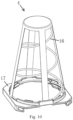
FIG. 10 schematically illustrates an elastic module of an elastic base pad of the elastic pad ofFIG. 4 . - 1-base plate, 2-limit boss, 3-elastic base pad, 4-elastic module, 5-receiving space, 6-flexible outer sleeve, 7-elastic member, 8-first limit boss, 9-second limit boss, 10-first row of limit bosses, 11-second row of limit bosses, 12-elastic pad, 13-balancing pad, 14-flexible pad, 15-outer cover, 6-conical spring, 17-spring support.
- Hereunder, the present disclosure will be described in detail with reference to the accompanying drawings. What have been described herein are merely preferred embodiments according to the present disclosure. Those skilled in the art can conceive of other ways of implementing the present disclosure on the basis of the preferred embodiments, and said other ways also fall within the scope of the present disclosure.
-
FIG. 1, FIG. 2 and FIG. 3 schematically illustrate abalancing pad 13 in use with elastic modules according to a preferred embodiment of the present disclosure. With reference toFIG. 1, FIG. 2 and FIG. 3 , thebalancing pad 13 provided by the disclosure comprises abase plate 1 and a plurality oflimit bosses 2, wherein the plurality oflimit bosses 2 are arranged to space apart from each other on and protrude from a plate surface of thebase plate 1, for example, thebase plate 1 comprises a first plate surface and a second plate surface which are opposite in a thickness direction of the base plate, the plurality oflimit bosses 2 are arranged on the first plate surface and extend away from thebase plate 1, the plurality oflimit bosses 2 form a plurality of receivingspaces 5 spaced apart from each other, and each of the plurality of receivingspace 5 is configured to receive correspondingelastic modules 4 of anelastic base pad 3 so as to constrain the movement of the correspondingelastic modules 4 in a transverse direction of the base plate. - In this technical solution, the plurality of
limit bosses 2 are arranged to space apart from each other on and protrude from a plate surface of thebase plate 1, and the plurality oflimit bosses 2 form the plurality of receivingspaces 5 spaced apart from each other, and the plurality of receivingspaces 5 can receive correspondingelastic modules 4 of theelastic base pad 3 so as to constrain the movement of the correspondingelastic modules 4 in the transverse direction of thebase plate 1. In this way, when assembled to form theelastic pad 12, thebalancing pad 13 may be laid on theelastic base pad 3 having the plurality ofelastic modules 4, and a portion of theelastic modules 4 may be received in the respective corresponding receivingspace 5. At this time, due to a transverse buffering and limiting action of thelimit bosses 2, when theelastic pad 12 is pressed to compress theelastic modules 4, thelimit bosses 2 may effectively constrain the movement of theelastic modules 4 in the transverse direction (i.e., in a direction parallel to the base plate 1), so as to effectively prevent theelastic modules 4 from tilting as receiving a force, thereby effectively maintaining the support stability of theelastic modules 4. Therefore, when laid on theelastic base pad 3, thebalancing pad 13 constrains the movement of the respectiveelastic modules 4 in the transverse direction, thereby effectively improving the stability of theelastic pad 12 when being subjected to a pressure, so that theelastic pad 12 has better comfort. - In addition, the balancing pad may be used to make elastic pads for furniture.
- In addition, in the
balancing pad 13, thelimit bosses 2 may be connected on the plate surface on one side of thebase plate 1 by adhesion, ultrasonic welding, loop-and-hook connection or in other manners. In addition, the number oflimit bosses 2 may be determined according to the number ofelastic modules 4, and therefore, the present disclosure does not limit the specific number oflimit bosses 2. - In addition, in some embodiments, since the
limit bosses 2 protrude from the plate surface on one side of thebase plate 1, sizes of cross-sections of thelimit bosses 2 may be the same in the protruding direction, so that an internal transverse dimension of the receivingspaces 5 may be made the same in the protruding direction, so that a portion of theelastic modules 4 may abut against thebase plate 1 after entering the receivingspace 5. Alternatively, in other embodiments, the cross-sectional size of thelimit boss 2 may be stepped in the protruding direction, so that a stop step may be formed in the receivingspace 5. As such, a portion of theelastic module 4 may abut against the stop step after entering the receivingspace 5. Alternatively, in other embodiments, referring toFIG. 1, FIG. 2 and FIG. 3 , the cross-sectional size of each of thelimit bosses 2 is gradually reduced in a direction away from the base plate 1 (in the protruding direction). For example, as shown inFIG. 3 , thelimit boss 2 may be formed as a frustum so that the inner size of the receivingspace 5 is gradually reduced in a direction closer to thebase plate 1, and a portion of theelastic module 4 may abut against a tapered outer peripheral surface of the frustum after entering into the receivingspace 5. Alternatively, theelastic module 4 may be formed as a frustum body whose conical surface slope may be the same as the conical surface slope of the frustum, so that a portion of the frustum body may form a conical surface fit with the frustum in the receivingspace 5 in a form-fitting manner, a portion of theelastic module 4 may be more stably and reliably received in the receivingspace 5, and thebalancing pad 13 provides a more stable and reliable constraint for theelastic module 4. - In addition, when the
limit boss 2 is formed as a frustum, the frustum may have a variety of shapes, for example, the frustum may be a polygonal frustum such as a quadrangular frustum. Alternatively, in an alternative embodiment, as shown inFIG. 1, FIG. 2 and FIG. 3 , thelimit boss 2 is formed as a truncated cone. Accordingly, theelastic module 4 may be formed as a truncated cone. As such, referring toFIG. 2 ,FIG. 4 ,FIG. 6, FIG. 7 andFIG. 8 , when the truncated cone enters the receivingspace 5, the conical surface of the truncated cone will form a conical surface fit with conical surfaces of the surrounding truncated cones. The conical surface fitting may not only limits theelastic module 4 in the transverse direction as well as the protruding direction (a direction perpendicular to the transverse direction), so that theelastic module 4 may be constrained more stably and reliably. - In addition, in some embodiments, the
base plate 1 may not deform when the elastic pad is subjected to a pressure, for example, thebase plate 1 may be a plastic plate having a predetermined thickness. Alternatively, in other embodiments, thebase plate 1 is made of a flexible material, so that thebase plate 1 is formed as a flexible body, that is, when the elastic pad is subjected to a pressure, thebase plate 1 will flexibly deform to provide buffering, thereby further enabling the limit bosses to constrain the movement of theelastic modules 4 in the transverse direction, and effectively improving the stability of theelastic pad 12 when subjected to a pressure, so that theelastic pad 12 presents better comfort. - In addition, the
base plate 1 may be a plastic cloth having a predetermined thickness, or may be a silica gel pad, or may be a cloth layer. Certainly, thebase plate 1 may be a single layer or may be multiple layers which are sequentially laminated and connected. For example, when thebase plate 1 is a cloth layer, it may include a single layer of canvas, or may include multiple layers of non-woven fabrics which are sequentially stacked. The multiple cloth layers may be joined together by an adhesive or ultrasonic welding. - In addition, in some embodiments, the
limit boss 2 may not elastically deform when the elastic pad is pressed, for example, thelimit boss 2 may be a plastic truncated cone. Alternatively, in an alternative embodiment, thelimit boss 2 is made of an elastic material such that thelimit boss 2 is formed as an elastic body. In this way, after the balancing pad is laid on theelastic base pad 3 to form theelastic pad 12, when the elastic pad is subjected to a pressure, theelastic module 4 will be correspondingly compressed to provide support. At this time, since thelimit boss 2 is formed as an elastic body, the elastic body will elastically deform to a certain degree to provide buffering, thereby further constraining the movement of theelastic modules 4 in the transverse direction, and effectively improving the stability of theelastic pad 12 when subjected to a pressure. Therefore, theelastic pad 12 presents better comfort. - In addition, the elastic body may be of various types, for example, one type of elastic body may be a silica colloid, or another type of elastic body may be a sponge, for example, a sponge with a high elasticity. The sponge is easy to shape into a desired shape, low in cost, and easy to breathe. Alternatively, referring to
FIG. 3 , in other types of elastic bodys, the elastic body may include a flexibleouter sleeve 6 and an elastic member 7 disposed within the flexibleouter sleeve 6. One end of the flexibleouter sleeve 6 is connected to thebase plate 1 and the other end of the flexibleouter sleeve 6 extends away from thebase plate 1. The flexibleouter sleeve 6 can flexibly deform and can increase a contact area with theelastic module 4, thereby better limiting the movement of theelastic module 4 in the transverse direction. In this way, after the balancing pad is laid on theelastic base pad 3 to form theelastic pad 12, when the elastic pad is subjected to a pressure, theelastic module 4 will be correspondingly compressed to provide support. At this time, the elastic member 7 elastically deforms to a certain degree and causes the flexibleouter sleeve 6 to elastically deform to provide buffering, thereby further constraining the movement of theelastic modules 4 in the transverse direction, and effectively improving the stability of theelastic pad 12 when subjected to a pressure. Therefore, theelastic pad 12 presents better comfort. - Additionally, in some embodiments, the flexible
outer sleeve 6 and thebase plate 1 may be formed from different materials. For example, the flexibleouter sleeve 6 may be formed of a plastic cloth and thebase plate 1 may be formed of a silicone pad. Alternatively, in other embodiments, the flexibleouter sleeve 6 and thebase plate 1 are formed from the same material. In this way, being made from the same material, the flexibleouter sleeve 6 and thebase plate 1 may be connected easily, and the cost may be reduced. - In addition, in some embodiments, the flexible
outer sleeve 6 is a non-woven fabric sleeve, thebase plate 1 is a non-woven fabric plate, and the non-woven fabric sleeve and the non-woven fabric plate may be connected by sewing, adhesion or ultrasonic welding. In addition, the nonwoven fabric may enable the balancing pad to have good resistance against moisture and air permeability, and the nonwoven fabric may make the balancing pad more flexible and lighter, which can further enhance the comfort of the elastic pad. - Additionally, in some embodiments, the elastic member 7 may be in a natural state within the flexible
outer sleeve 6 when not subjected to a pressure. Alternatively, in other embodiments, with reference toFIG. 3 , one end of the elastic member 7 is connected to the plate surface of thebase plate 1, and the other end of the elastic member 7 is connected to an end cap at an end of the flexibleouter sleeve 6 far away from the plate surface so that the elastic member 7 is in a pre-compressed state. In this way, by means of the flexibleouter sleeve 6 and thebase plate 1, the elastic member 7 may be made in a pre-compressed state while itself has a certain elastic strength. As such, better elastic limitation may be further provided to theelastic modules 4. - In addition, in some embodiments, an outer peripheral profile of the elastic member 7 wrapped within the flexible
outer sleeve 6 may keep a gap with a side sleeve wall of the flexibleouter sleeve 6. Alternatively, in other embodiments, with reference toFIG. 3 , the outer peripheral profile of the elastic member 7 is pressed against an inner peripheral surface of the outer sleeve. As such, the elastic member 7, e.g., the elastic member 7 in the pre-compressed state, may make the flexibleouter sleeve 6 in a tensioned state, such that the outer peripheral surface of the flexibleouter sleeve 6 can better contact with theelastic modules 4 to better limit theelastic modules 4 in the transverse direction. - In addition, the elastic member 7 may be of various types, for example, in some embodiments, the elastic member 7 may be a silicone body such as a silicone truncated cone. Alternatively, in other embodiments, the elastic member 7 is a spring that provides good pre-compression strength and transverse limitation. The spring may be an equal-diameter spring, or may be a truncated cone-shaped spring as shown in
FIG. 3 . For example, when the truncated cone-shaped spring is used, the flexibleouter sleeve 6 made of a non-woven fabric may be truncated cone-shaped, thereby forming thelimit boss 2 as a truncated cone body. - In addition, in the
balancing pad 13 of the present disclosure, the number and arrangement manner of thelimit bosses 2 may be determined according to actual needs, and are not specifically limited in the present disclosure. For example, in some embodiments, each receivingspace 5 may be enclosed byindependent limit bosses 2 which are not shared by other receiving spaces. Alternatively, in other embodiments, with reference toFIG. 2 andFIG. 8 , adjacent receivingspaces 5 may share somelimit bosses 2. For example, thelimit boss 2 may comprise a plurality offirst limit bosses 8 and a plurality ofsecond limit bosses 9, wherein each receivingspace 5 is surrounded by the plurality offirst limit bosses 8 and the plurality ofsecond limit bosses 9 arranged alternately in sequence, wherein each of thefirst limit bosses 8 is surrounded by thesecond limit bosses 9 of the surrounding multiple receivingspaces 5. In this way, eachfirst limit boss 8, while used to enclose the receivingspace 5, is also enclosed at a center by the surroundingsecond limit bosses 9, so that eachfirst limit boss 8 may limit the surroundingsecond limit bosses 9 in the transverse direction, thereby enabling thesecond limit bosses 9 to more stably and reliably constrain theelastic module 4 entering the receivingspace 5 in the transverse direction. - In addition, in some embodiments, the plurality of
first limit bosses 8 and the plurality ofsecond limit bosses 9 may not be arranged in rows and columns on thebase plate 1. Alternatively, in other embodiments, with reference toFIG. 2 andFIG. 8 , a plurality of first-row limit bosses 10 and second-row limit bosses 11 arranged alternately in sequence are provided on a plate surface on one side of thebase plate 1, wherein each row of the first-row limit bosses 10 comprises a plurality offirst limit bosses 8 andsecond limit bosses 9 adjacent alternately in sequence in the row direction; each row of the second-row limit boss 11 comprises a plurality ofsecond limit bosses 9 arranged apart from each other at an interval in the row direction, the interval being onesecond limit boss 9; wherein eachsecond limit boss 9 in each row of second-row limit bosses 11 is aligned with eachfirst limit boss 8 of an adjacent row in a columnwise direction such that the interval serves as the receivingspace 5. Thus, as shown in the figure, fourfirst limit bosses 8 and foursecond limit bosses 9 are squarely arranged to together enclose a receivingspace 5, the fourfirst limit bosses 8 are respectively at four corner positions, and thefirst limit boss 8 at each corner position is enclosed in the middle by the foursecond limit bosses 9 of surrounding receivingspaces 5, so that adjacent receivingspaces 5 can share some of thefirst limit bosses 8 and thesecond limit bosses 9, thereby better constraining the movement of theelastic modules 4 in the transverse direction by virtue of such a constraining structure between the limit bosses. - In addition, referring to
FIG. 4, FIG. 5 ,FIG. 6, FIG. 7 andFIG. 8 , the present disclosure provides anelastic pad 12 including anelastic base pad 3 and the above-describedbalancing pad 13, wherein theelastic base pad 3 comprises a plurality ofelastic modules 4, wherein thebalancing pad 13 is laid on the elastic basedpad 3, and the plurality ofelastic modules 4 are received inrespective receiving spaces 5, and wherein the limit bosses can constrain movement of theelastic modules 4 in the transverse direction. - As described above, since the balancing pad constrains the movement of the elastic modules in the transverse direction when laid on the elastic base pad, the stability of the elastic pad when subjected to a pressure can be effectively improved so that the elastic pad exhibit better comfort.
- In addition, the
elastic module 4 may have various shapes, for example, theelastic module 4 may be in the shape of a cylinder, a truncated cone or a column. In some embodiments, referring toFIG. 6 , theelastic module 4 is formed in a truncated cone shape and is made to contact at least onelimit boss 2 in a form of a truncated cone, so that theelastic module 4 has a truncated cone shape and is received in the receivingspace 5; a conical surface of the truncated cone-shapedelastic module 4 and thelimit boss 2 in the form of the truncated cone have the same slope, so as to form a conical surface fit with a shape-fitting manner therebetween, so that a part of theelastic module 4 can be fitted more stably and reliably in the receivingspace 5, and thebalancing pad 13 provides a more stable and reliable constraint to theelastic module 4. - In addition, the
elastic module 4 may be of various types, for example, theelastic module 4 may be a column-shaped elastic block such as a rubber block. Alternatively, referring toFIG. 10 , theelastic module 4 may include aspring bracket 17 and aconical spring 16 disposed in thespring bracket 17. At this time, the elastic basedpad 4 may include a foldable mounting support, theelastic bracket 17 is used to detachably mount theelastic module 4 to the foldable mounting support. In this way, a plurality ofelastic modules 4 may be mounted to the foldable mounting supports by means ofrespective spring brackets 17, and then thebalancing pad 13 may be laid on theelastic modules 4 so that a portion of eachelastic module 4 enters and gets positioned in the corresponding receivingspace 5. Upon disassembly, thebalancing pad 13 is removed, and then theelastic modules 4 are removed from the foldable mounting supports and sequentially nested and stacked together, and then the foldable mounting supports are folded. Therefore, theelastic pad 12 can be easily detached, and the removed elastic modules can be compressed or stacked and nested together, thereby greatly saving the storage and transportation space, and facilitating cleaning. - In addition, referring to
FIG. 9 , the elastic pad further includes aflexible pad 14 and anouter cover 15, wherein theflexible pad 14 is laid on thebase plate 1, and theouter cover 15 covers theflexible pad 14 and wraps around thebalancing pad 13, theflexible pad 14 and at least a part of theelastic base pad 3. For example, theouter cover 15 may wrap theelastic base pad 3 and thebalancing pad 13 entirely, thereby enhancing the aesthetic appearance of theelastic pad 12. Theouter cover 15 may enclose at least a portion of theelastic base pad 3 and thebalancing pad 13 by a removable connection structure such as a zipper or a loop-and-hook. Theflexible pad 14 may be a silicone pad or a cotton pad or a sponge pad such as a highly elastic sponge pad, or may be a flexible pad of other materials. - In addition, the present disclosure provides a furniture comprising the above-described
elastic pad 12. As stated above, the comfort of the furniture is significantly improved. Such furniture includes, but is not limited to, mattresses, sofas, chairs, sofa beds, soft-packaged benches, and the like. - The scope of protection of the present disclosure is defined only by the appended claims. Given the teaching of the present disclosure, those skilled in the art could easily envision using alternative structures of those disclosed herein as feasible alternative embodiments, and combining the embodiments disclosed herein to form new embodiments, which should all fall into the scope defined by the appended claims.
Claims (17)
- A balancing pad in use with elastic modules, comprising a base plate (1) and a plurality of limit bosses (2) arranged to space apart from each other on and protrude from a plate surface of the base plate (1), the plurality of limit bosses (2) form a plurality of receiving spaces (5) spaced apart from each other, and each of the plurality of receiving spaces (5) is configured to receive a corresponding elastic modules (4) of an elastic base pad (3) so as to constrain the movement of the corresponding elastic modules (4) in a transverse direction of the base plate.
- The balancing pad in use with elastic modules according to claim 1, wherein a cross-sectional size of each of the plurality of limit bosses (2) is gradually reduced in a direction away from the base plate (1) so that an inner size of the receiving space (5) is gradually reduced in a direction closer to the base plate (1).
- The balancing pad in use with elastic modules according to claim 2, wherein each of the plurality of limit bosses (2) is formed as a truncated body.
- The balancing pad in use with elastic modules according to claim 1, wherein the based plate (1) is made of flexible material.
- The balancing pad in use with elastic modules according to any of claims 1-4, wherein each of the plurality of limit bosses (2) is made of elastic material and formed as an elastic body.
- The balancing pad in use with elastic modules according to claim 5, wherein the elastic body comprises a flexible outer sleeve (6) and an elastic member (7), the elastic member (7) is disposed within the flexible outer sleeve (6), wherein one end of the flexible outer sleeve (6) is connected to the base plate (1), and the other end of the flexible outer sleeve extends away from the base plate (1).
- The balancing pad in use with elastic modules according to claim 6, wherein the flexible outer sleeve (6) and the base plate (1) are formed from the same material.
- The balancing pad in use with elastic modules according to claim 7, wherein the flexible outer sleeve (6) is a nonwoven fabric sleeve, and the base plate (1) is a nonwoven fabric plate.
- The balancing pad in use with elastic modules according to claim 6, wherein one end of the elastic member (7) is connected to the plate surface of the base plate (1), and the other end of the elastic member (7) is connected to an end cap at an end of the flexible outer sleeve (6) far away from the plate surface so that the elastic member (7) is in a pre-compressed state.
- The balancing pad in use with elastic modules according to claim 6, wherein an outer peripheral profile of the elastic member (7) is pressed against an inner peripheral surface of the flexible outer sleeve.
- The balancing pad in use with elastic modules according to claim 6, wherein the elastic member (7) is a spring.
- The balancing pad in use with elastic modules according to claim 1, wherein the plurality of limit bosses (2) comprise a plurality of first limit bosses (8) and a plurality of second limit bosses (9), wherein each of the receiving spaces (5) is surrounded by the plurality of first limit bosses (8) and the plurality of second limit bosses (9) arranged alternately in sequence, wherein each of the first limit bosses (8) is surrounded by the second limit bosses (9) of surrounding multiple receiving spaces (5).
- The balancing pad in use with elastic modules according to claim 12, wherein a plurality of first-row limit bosses (10) and second-row limit bosses (11) arranged alternately in sequence are provided on a plate surface on one side of the base plate (1), whereineach row of the first-row limit bosses (10) comprises a plurality of first limit bosses (8) and second limit bosses (9) adjacent alternately in sequence in a row direction;each row of the second-row limit bosses (11) comprises a plurality of second limit bosses (9) arranged apart from each other at an interval in the row direction, the interval being one said second limit boss (9);wherein each said second limit boss (9) in each row of said second-row limit bosses (11) is aligned with each said first limit boss (8) of an adjacent row in a columnwise direction such that the interval serves as the receiving space (5).
- An elastic pad (12), comprisingan elastic base pad (3) comprising a plurality of elastic modules (4);the balancing pad (13) in use with elastic modules according to any of claims 1-13;wherein the balancing pad (13) is laid on the elastic based pad (3), and the plurality of elastic modules (4) are received in the respective receiving spaces (5), and wherein the limit bosses (2) can constrain the movement of the elastic modules (4) in a transverse direction.
- The elastic pad according to claim 14, wherein the elastic module (4) is formed in a truncated cone shape and is made to contact at least one limit boss (2) in a form of a truncated cone.
- The elastic pad according to claim 14 or 15, wherein the elastic pad further comprises a flexible pad (14) and an outer cover (15), wherein the flexible pad (14) is laid on the base plate (1), and the outer cover (15) covers the flexible pad (14) and wraps around the balancing pad (13), the flexible pad (14) and at least a part of the elastic base pad (3).
- A furniture, comprising the elastic pad (12) according to any of claims 14-16.
Applications Claiming Priority (2)
| Application Number | Priority Date | Filing Date | Title |
|---|---|---|---|
| CN202110925502.5A CN115191785B (en) | 2021-08-12 | 2021-08-12 | Elastic module balance pad, elastic pad and furniture |
| PCT/CN2022/110296 WO2023016343A1 (en) | 2021-08-12 | 2022-08-04 | Elastic module balance cushion, elastic cushion, and furniture |
Publications (2)
| Publication Number | Publication Date |
|---|---|
| EP4385367A1 true EP4385367A1 (en) | 2024-06-19 |
| EP4385367A4 EP4385367A4 (en) | 2025-07-23 |
Family
ID=83573891
Family Applications (1)
| Application Number | Title | Priority Date | Filing Date |
|---|---|---|---|
| EP22855326.9A Pending EP4385367A4 (en) | 2021-08-12 | 2022-08-04 | Balancing cushion for an elastic module, elastic cushion and furniture |
Country Status (5)
| Country | Link |
|---|---|
| US (1) | US20240349904A1 (en) |
| EP (1) | EP4385367A4 (en) |
| JP (1) | JP7739594B2 (en) |
| CN (1) | CN115191785B (en) |
| WO (1) | WO2023016343A1 (en) |
Families Citing this family (10)
| Publication number | Priority date | Publication date | Assignee | Title |
|---|---|---|---|---|
| SE544841C2 (en) * | 2021-01-22 | 2022-12-13 | Ikea Supply Ag | Mattress spring core arranged with spring pockets allowing improved shape and size stability |
| KR20250024965A (en) | 2022-06-17 | 2025-02-20 | 뉴-텍 인티그레이션 (샤먼) 컴퍼니 리미티드 | Elastic pads, elastic pad assembly method and furniture |
| CN115670171B (en) * | 2022-10-24 | 2025-09-26 | 厦门新技术集成有限公司 | Flexible modular units, flexible mats and furniture |
| CN115717465A (en) * | 2022-12-02 | 2023-02-28 | 福建思嘉环保材料科技有限公司 | Environment-friendly sports floor based on high-flame-retardant argil composite material |
| CN115844162B (en) * | 2022-12-19 | 2025-04-08 | 厦门新技术集成有限公司 | Elastic support assembly, elastic pad, assembly method thereof and furniture |
| CN118285644A (en) * | 2023-01-04 | 2024-07-05 | 厦门新技术集成有限公司 | Cover, elastic pad and furniture |
| CN116172360B (en) * | 2023-01-31 | 2025-12-09 | 厦门新技术集成有限公司 | Elastic pad and elastic assembly for elastic pad |
| CN116473388B (en) * | 2023-01-31 | 2026-01-23 | 厦门新技术集成有限公司 | Elastic cushion |
| CN116763095A (en) * | 2023-05-05 | 2023-09-19 | 厦门新技术集成有限公司 | Balance plate and flexible pad with same |
| CN121337143A (en) * | 2024-07-16 | 2026-01-16 | 厦门新技术集成有限公司 | Floating bed |
Family Cites Families (19)
| Publication number | Priority date | Publication date | Assignee | Title |
|---|---|---|---|---|
| JP3553346B2 (en) * | 1997-10-30 | 2004-08-11 | ドリームベッド株式会社 | Pocket coil structure made of morning glory spring |
| JP2004041602A (en) * | 2002-07-16 | 2004-02-12 | Smc Japan:Kk | Cushion spring unit of seat or the like |
| JP5339590B2 (en) * | 2008-11-07 | 2013-11-13 | フランスベッド株式会社 | Mattress equipment |
| JP5227243B2 (en) * | 2009-04-23 | 2013-07-03 | 株式会社ニトリホールディングス | mattress |
| DK2967222T3 (en) * | 2013-03-14 | 2018-03-05 | Sealy Technology Llc | COVERED ASYMMETRIC SPIRAL SPRING INSERT WITH ALTERNATIVE ORIENTATIONS OF THE SPIRAL SPRING |
| EP2801297A1 (en) * | 2013-05-08 | 2014-11-12 | You Bed AB | Furniture device with adjustable firmness |
| CN203555438U (en) * | 2013-11-13 | 2014-04-23 | 覃启军 | Spring cushion core structure of spring mattress |
| CN204169490U (en) * | 2014-10-26 | 2015-02-25 | 李海仁 | A kind of elastic bamboo bed pad |
| CN205457541U (en) * | 2016-02-02 | 2016-08-17 | 福建省泉州大富豪家具有限公司 | Hydrotherapy mattress |
| CN205903086U (en) * | 2016-04-07 | 2017-01-25 | 普悠思玛国际有限公司 | Elastic mattress |
| CN206933850U (en) * | 2016-10-25 | 2018-01-30 | 长沙华嵘环境科技有限公司 | Mattress |
| CN207220572U (en) * | 2017-03-16 | 2018-04-13 | 长沙华嵘环境科技有限公司 | Mattress |
| US10334958B2 (en) * | 2017-05-09 | 2019-07-02 | L&P Property Management Company | Glueless pocketed spring assembly with improved airflow |
| US10881217B2 (en) * | 2017-07-28 | 2021-01-05 | Purple Innovation, Llc | Mattresses including spacer fabric and related methods |
| CN208692681U (en) * | 2017-08-14 | 2019-04-05 | 安吉万昌家具有限公司 | A kind of ventilative radiating bed spring mattress |
| CN208709092U (en) * | 2017-12-07 | 2019-04-09 | 广州市联柔机械设备有限公司 | A kind of bagged-spring and bagged spring bed core of band softness bed course |
| CN112674536B (en) * | 2019-10-17 | 2024-08-02 | 厦门新技术集成有限公司 | Elastic module and elastic pad for furniture |
| CN212698296U (en) * | 2020-08-10 | 2021-03-16 | 合肥皖宝集团床垫有限公司 | Spring-free mattress structure with adjustable elasticity |
| CN213757509U (en) * | 2020-12-24 | 2021-07-23 | 喜临门家具股份有限公司 | Mattress with good use experience |
-
2021
- 2021-08-12 CN CN202110925502.5A patent/CN115191785B/en active Active
-
2022
- 2022-08-04 US US18/682,846 patent/US20240349904A1/en active Pending
- 2022-08-04 EP EP22855326.9A patent/EP4385367A4/en active Pending
- 2022-08-04 WO PCT/CN2022/110296 patent/WO2023016343A1/en not_active Ceased
- 2022-08-04 JP JP2024507900A patent/JP7739594B2/en active Active
Also Published As
| Publication number | Publication date |
|---|---|
| WO2023016343A1 (en) | 2023-02-16 |
| JP7739594B2 (en) | 2025-09-16 |
| CN115191785B (en) | 2023-08-11 |
| CN115191785A (en) | 2022-10-18 |
| JP2024529551A (en) | 2024-08-06 |
| US20240349904A1 (en) | 2024-10-24 |
| EP4385367A4 (en) | 2025-07-23 |
Similar Documents
| Publication | Publication Date | Title |
|---|---|---|
| EP4385367A1 (en) | Elastic module balance cushion, elastic cushion, and furniture | |
| EP4385366A1 (en) | Elastic module balancing cushion, elastic cushion and furniture | |
| US20240423383A1 (en) | Elastic module, elastic mattress and furniture | |
| US20240285089A1 (en) | Elastic module and elastic mattress | |
| CN215533110U (en) | Elastic module balance pad, elastic pad and furniture | |
| EP4385368A1 (en) | Elastic module balancing cushion, elastic cushion, and furniture | |
| CN101568281A (en) | A mattress | |
| US20250024959A1 (en) | Elastic support module, elastic pad, and furniture | |
| CN116250695A (en) | Elastic unit, elastic module and elastic pad | |
| KR20250068656A (en) | Elastic module units, elastic cushions and furniture | |
| KR200479160Y1 (en) | Puzzle prefabricated mattress | |
| JP6614613B2 (en) | Padding | |
| AU2013213967B2 (en) | A tie arrangement | |
| JP2024529780A (en) | Elastic cushions and furniture | |
| JP2025530842A (en) | Supportive underlays and elastic cushions and furniture | |
| KR102366492B1 (en) | A folding mattress | |
| CN218551890U (en) | Balance Pads, Resilient Pads and Furniture | |
| CN120345786A (en) | Compressible seat with spring skeleton | |
| KR102285166B1 (en) | Mattress | |
| US20110296616A1 (en) | Cushion with a stiffening insert | |
| GB2128082A (en) | Beds and other articles of furniture |
Legal Events
| Date | Code | Title | Description |
|---|---|---|---|
| STAA | Information on the status of an ep patent application or granted ep patent |
Free format text: STATUS: THE INTERNATIONAL PUBLICATION HAS BEEN MADE |
|
| PUAI | Public reference made under article 153(3) epc to a published international application that has entered the european phase |
Free format text: ORIGINAL CODE: 0009012 |
|
| STAA | Information on the status of an ep patent application or granted ep patent |
Free format text: STATUS: REQUEST FOR EXAMINATION WAS MADE |
|
| 17P | Request for examination filed |
Effective date: 20240306 |
|
| AK | Designated contracting states |
Kind code of ref document: A1 Designated state(s): AL AT BE BG CH CY CZ DE DK EE ES FI FR GB GR HR HU IE IS IT LI LT LU LV MC MK MT NL NO PL PT RO RS SE SI SK SM TR |
|
| DAV | Request for validation of the european patent (deleted) | ||
| DAX | Request for extension of the european patent (deleted) | ||
| A4 | Supplementary search report drawn up and despatched |
Effective date: 20250620 |
|
| RIC1 | Information provided on ipc code assigned before grant |
Ipc: A47C 27/05 20060101AFI20250613BHEP Ipc: A47C 23/00 20060101ALI20250613BHEP Ipc: A47C 27/06 20060101ALI20250613BHEP Ipc: A47C 27/07 20060101ALI20250613BHEP |
|
| STAA | Information on the status of an ep patent application or granted ep patent |
Free format text: STATUS: EXAMINATION IS IN PROGRESS |
|
| 17Q | First examination report despatched |
Effective date: 20251208 |