EP4385681B1 - Saugkissen - Google Patents
Saugkissen Download PDFInfo
- Publication number
- EP4385681B1 EP4385681B1 EP23214510.2A EP23214510A EP4385681B1 EP 4385681 B1 EP4385681 B1 EP 4385681B1 EP 23214510 A EP23214510 A EP 23214510A EP 4385681 B1 EP4385681 B1 EP 4385681B1
- Authority
- EP
- European Patent Office
- Prior art keywords
- workpiece
- pressure
- cavity
- suction
- cavities
- Prior art date
- Legal status (The legal status is an assumption and is not a legal conclusion. Google has not performed a legal analysis and makes no representation as to the accuracy of the status listed.)
- Active
Links
Images


Classifications
-
- B—PERFORMING OPERATIONS; TRANSPORTING
- B25—HAND TOOLS; PORTABLE POWER-DRIVEN TOOLS; MANIPULATORS
- B25J—MANIPULATORS; CHAMBERS PROVIDED WITH MANIPULATION DEVICES
- B25J15/00—Gripping heads and other end effectors
- B25J15/06—Gripping heads and other end effectors with vacuum or magnetic holding means
- B25J15/0616—Gripping heads and other end effectors with vacuum or magnetic holding means with vacuum
- B25J15/0625—Gripping heads and other end effectors with vacuum or magnetic holding means with vacuum provided with a valve
- B25J15/0633—Air-flow-actuated valves
-
- B—PERFORMING OPERATIONS; TRANSPORTING
- B65—CONVEYING; PACKING; STORING; HANDLING THIN OR FILAMENTARY MATERIAL
- B65G—TRANSPORT OR STORAGE DEVICES, e.g. CONVEYORS FOR LOADING OR TIPPING, SHOP CONVEYOR SYSTEMS OR PNEUMATIC TUBE CONVEYORS
- B65G47/00—Article or material-handling devices associated with conveyors; Methods employing such devices
- B65G47/74—Feeding, transfer, or discharging devices of particular kinds or types
- B65G47/90—Devices for picking-up and depositing articles or materials
- B65G47/91—Devices for picking-up and depositing articles or materials incorporating pneumatic, e.g. suction, grippers
-
- B—PERFORMING OPERATIONS; TRANSPORTING
- B25—HAND TOOLS; PORTABLE POWER-DRIVEN TOOLS; MANIPULATORS
- B25B—TOOLS OR BENCH DEVICES NOT OTHERWISE PROVIDED FOR, FOR FASTENING, CONNECTING, DISENGAGING, OR HOLDING
- B25B11/00—Work holders not covered by any preceding group in the subclass, e.g. magnetic work holders, vacuum work holders
- B25B11/005—Vacuum work holders
-
- B—PERFORMING OPERATIONS; TRANSPORTING
- B25—HAND TOOLS; PORTABLE POWER-DRIVEN TOOLS; MANIPULATORS
- B25J—MANIPULATORS; CHAMBERS PROVIDED WITH MANIPULATION DEVICES
- B25J13/00—Controls for manipulators
- B25J13/08—Controls for manipulators by means of sensing devices, e.g. viewing or touching devices
- B25J13/087—Controls for manipulators by means of sensing devices, e.g. viewing or touching devices for sensing other physical parameters, e.g. electrical or chemical properties
-
- B—PERFORMING OPERATIONS; TRANSPORTING
- B25—HAND TOOLS; PORTABLE POWER-DRIVEN TOOLS; MANIPULATORS
- B25J—MANIPULATORS; CHAMBERS PROVIDED WITH MANIPULATION DEVICES
- B25J15/00—Gripping heads and other end effectors
- B25J15/06—Gripping heads and other end effectors with vacuum or magnetic holding means
- B25J15/0616—Gripping heads and other end effectors with vacuum or magnetic holding means with vacuum
- B25J15/0625—Gripping heads and other end effectors with vacuum or magnetic holding means with vacuum provided with a valve
-
- B—PERFORMING OPERATIONS; TRANSPORTING
- B25—HAND TOOLS; PORTABLE POWER-DRIVEN TOOLS; MANIPULATORS
- B25J—MANIPULATORS; CHAMBERS PROVIDED WITH MANIPULATION DEVICES
- B25J15/00—Gripping heads and other end effectors
- B25J15/06—Gripping heads and other end effectors with vacuum or magnetic holding means
- B25J15/0616—Gripping heads and other end effectors with vacuum or magnetic holding means with vacuum
- B25J15/0691—Suction pad made out of porous material, e.g. sponge or foam
Definitions
- the present invention relates to a suction pad for sucking a workpiece using vacuum pressure, and more particularly to a suction pad capable of confirming the suction state of the workpiece.
- a suction pad that sucks a workpiece by bringing a sponge member made of a porous material into contact with the workpiece and generating vacuum pressure inside the sponge member.
- a technique for detecting the suction state of a workpiece by detecting pressure in a path through which vacuum pressure is introduced into a suction pad.
- JP 2022-017935 A discloses a suction pad including an inner sponge pad formed of an open cell sponge having air permeability, and an outer sponge pad formed of a closed cell sponge having no air permeability.
- a pressure sensor is disposed on a path through which the suction pad is connected to an ejector, and the suction state of the workpiece sucked by the inner sponge pad and the suction state of the workpiece sucked by the outer sponge pad are sequentially detected.
- US 2019/0248025 A1 US 2021/0053192 A1 and JP 2007-331056 A can be listed.
- US 2019/0248025 A1 discloses a gripper assembly including a vacuum generation head, a plenum block, a check valve plate, and a gripper having foam structure.
- the check valve plate is formed of a number of chambers, and each of the chambers includes an opening facing the bottom, a ball blocking a vacuum supply conduit, an opening connected to the plenum block, and a pressure sensor.
- Each of the openings and each of the chambers individually correspond to a plurality of holes (ports) of the gripper.
- the vacuum supply conduit corresponding to the port in contact with the workpiece is not to be blocked by the ball and the corresponding pressure sensor indicates vacuum pressure.
- the vacuum supply conduit corresponding to the port out of contact with the workpiece is to be blocked by the ball and the pressure sensor indicates atmospheric pressure.
- US 2021/0053192 A1 discloses a suction device having a body including a cavity and an open end of the cavity functioning as a suction face to suck a workpiece.
- a tangential nozzle is disposed on a sidewall surface of the cavity.
- a suction hole is disposed on the closed end face of the cavity. The suction hole is connected to a suction unit.
- US 2021/0053192 A1 discloses a suction device provided with a pressure detection unit to monitor the fluid pressure in the cavity.
- JP 2007-331056 A discloses a vacuum suction device capable of estimating a suction area and a suction force.
- This vacuum suction device includes a vacuum suction pad, an air injection means, a depressurization means, a positive pressure measurement means, a negative pressure measurement means, a conduit for pressurization and a conduit for depressurization.
- the vacuum suction pad includes a vacuum chamber forming unit internally forming a vacuum chamber, a suction unit having a workpiece suction face and a check valve forming unit.
- the suction unit is formed of a sponge material or the like and provided with a plurality of suction paths in communication with an external space and the vacuum chamber.
- the check valve forming unit includes a plurality of check valves each arranged at each of the suction paths.
- check valves flow passage adjustment valves
- a vacuum suction device that includes a plurality of suction portions (suction pads) and is capable of sucking workpieces of various sizes
- check valves flow passage adjustment valves
- the vacuum pressure required for sucking the workpiece acts on the workpiece effectively.
- a large sponge pad including a large number of suction holes is used to suck workpieces of various sizes, it is desirable to dispose check valves as well.
- the suction state of the workpiece cannot be easily confirmed by simply disposing the pressure sensor. This is because, since the vacuum pressure is maintained by the action of the check valves regardless of whether the workpiece is being sucked or is not being sucked, there is no difference between the pressures detected by the pressure sensor, and the state where the workpiece is being sucked and the state where the workpiece is not being sucked cannot be distinguished from each other.
- the present invention has the object of solving the aforementioned problem.
- the suction pad according to the present invention has a structure in which the flow passage adjustment valves are disposed in the communication passages connecting the cavities of the sponge member to the negative pressure chamber, and includes the pressure detection port for detecting the pressure in at least one cavity of the sponge member. Therefore, it is possible to easily confirm whether or not the workpiece is being sucked.
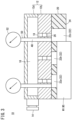
- FIG. 1 A suction pad 10 according to a first embodiment of the present invention will be described with reference to FIGS. 1 to 5 .
- the suction pad 10 includes a body 12 and a sponge member 20.
- the suction pad 10 when terms in relation to upper and lower directions are used, such terms refer to the directions shown in the drawings, however, the actual arrangement of the respective constituent members is not limited thereby.
- the body 12 is formed of a main body 12a that has a box shape and opens downward, and a plate 12b that is thick and covers the main body 12a from below.
- the main body 12a includes a suction port 14 connected to a vacuum generator (not shown).
- the body 12 includes therein a negative pressure chamber 16 communicating with the suction port 14.
- the plate 12b includes a plurality of communication passages 18 communicating with the negative pressure chamber 16.
- the sponge member 20 having a plate shape is attached to a lower surface of the plate 12b by means of bonding or the like.
- the sponge member 20 includes a plurality of cavities 22 opening toward a workpiece W.
- the cavities 22 of the sponge member 20 communicate with the negative pressure chamber 16 through the communication passages 18 of the plate 12b.
- the sponge member 20 comes into contact with the workpiece W at a lower surface (bottom surface) 24 thereof.
- the sponge member 20 is made of a material having a semi-open and semi-closed cell structure, and is manufactured by foam-molding ethylene propylene rubber (EPDM), for example.
- EPDM ethylene propylene rubber
- the sponge member 20 exhibits flexibility which is a property of open cells until it is compressed by a predetermined amount from a natural state, and exhibits airtightness which is a property of closed cells after it is compressed by the predetermined amount.
- the sponge member 20 can be deformed in accordance with the surface shape of the workpiece W by exhibiting flexibility. Even if the workpiece W has irregularities on its surface as in the case of a cardboard box in which beverage containers are packaged, no gap is generated between the sponge member 20 and the workpiece W. The sponge member 20 comes into close contact with the workpiece W and then exhibits airtightness to cause vacuum pressure required for sucking the workpiece W to act on the workpiece W.
- the thickness of the sponge member 20 when no vertical compressive force is applied to the sponge member 20 is represented by T0, and the thickness of the sponge member 20 when a vertical compressive force is applied to the sponge member 20 is represented by T.
- a compression amount (%) of the sponge member 20 is defined as (T0 - T)/T0 ⁇ 100.
- the sponge member 20 exhibits sufficient airtightness when compressed to a compression amount of at least about 70 %, for example.
- a flow passage adjustment valve 26 is arranged in the middle of each communication passage 18 of the body 12.
- the flow passage adjustment valve 26 adjusts the flow passage area of the communication passage 18 in accordance with the suction state of the workpiece W.
- the flow passage area of the communication passage 18 is sufficiently increased, and the pressure in the cavity 22 becomes equal to the pressure in the negative pressure chamber 16. That is, when the cavity 22 is closed by the workpiece W, the same vacuum pressure as the vacuum pressure generated in the negative pressure chamber 16 is generated in the cavity 22.
- the flow passage area of the communication passage 18 is sufficiently decreased, and high vacuum pressure is generated in the negative pressure chamber 16, while the pressure in the cavity 22 becomes substantially equal to the atmospheric pressure.
- the flow passage adjustment valve 26 includes a first joint member 28, a second joint member 32, and a valve element 36.
- the tubular valve element 36 is disposed inside the tubular first joint member 28, and can be vertically displaced with respect to the first joint member 28.
- the first joint member 28 is provided with a tapered seat portion 30 against which a head part 38 of the valve element 36 can abut.
- the tubular second joint member 32 is connected and fixed to the first joint member 28.
- a stopper 34 capable of abutting against a lower end of the valve element 36 is attached to the second joint member 32. By the valve element 36 abutting against the stopper 34, downward displacement of the valve element 36 is regulated.
- the head part 38 of the valve element 36 includes an orifice 40 at its center, and the orifice 40 communicates with an inner space 44 of the valve element 36.
- a sidewall of the valve element 36 includes a plurality of openings 42 that communicate with the inner space 44 of the valve element 36. The area of the opening 42 is sufficiently larger than the area of the orifice 40.
- the inner space 44 of the valve element 36 communicates, at the lower end thereof, with an internal space of the second joint member 32.
- a spring 46 for biasing the valve element 36 downward is disposed between the first joint member 28 and the valve element 36.
- the suction pad 10 can suck workpieces W of various sizes.
- the pressure in the negative pressure chamber 16 of the body 12 does not increase even if the workpiece W is small enough to contact only a part of the bottom surface 24 of the sponge member 20 and one or some of the cavities 22 of the sponge member 20 are open to the atmosphere. That is, even if there is a cavity 22 which is not closed by the workpiece W, the vacuum pressure generated in the negative pressure chamber 16 does not decrease due to the action of the flow passage adjustment valve 26.
- the body 12 includes a detection passage 48 for detecting the pressure in a predetermined cavity 22 of the sponge member 20.
- the detection passage 48 is arranged for each of one or more selected cavities 22.
- the detection passage 48 vertically passes through the negative pressure chamber 16 and extends from an upper surface to a lower surface of the body 12, and a lower end of the detection passage 48 communicates with the corresponding cavity 22.
- An upper end of each detection passage 48 forms a pressure detection port 50.
- a pressure sensor 52 is individually connected to each pressure detection port 50. The pressure in the selected cavity 22 is detected by the pressure sensor 52.
- the cavity 22 for which the detection passage 48 is correspondingly arranged is determined in consideration of the size of the workpiece W to be sucked.
- the detection passages 48 are arranged corresponding to one or more cavities 22 closed by the workpiece W, and one or more cavities 22 that are not closed by the workpiece W.
- FIG. 1 shows three cavities 22a to 22c.
- the detection passages 48 and the pressure sensors 52 are arranged corresponding to the cavity 22a and the cavity 22c among the three cavities.
- the suction pad 10 is used by being attached to, for example, a conveying device (not shown).
- a host controller such as a PLC
- the conveying device is driven and the suction pad 10 comes into contact with the workpiece W.
- air in the negative pressure chamber 16 is sucked from the suction port 14 toward the vacuum generator.
- the flow passage areas of the communication passages 18 are reduced by the flow passage adjustment valves 26. Therefore, high vacuum pressure is easily generated in the negative pressure chamber 16.
- the cavity 22a and the cavity 22b are closed by the workpiece W1, and the cavity 22c is not closed by the workpiece W1.
- the cavities 22a and 22b closed by the workpiece W1 communicate with the negative pressure chamber 16 through the communication passages 18 whose flow passage areas are sufficiently increased by the flow passage adjustment valves 26. Therefore, the vacuum pressure generated in the negative pressure chamber 16 is directly transmitted to the cavities 22a and 22b and acts on an upper surface portion of the workpiece W1 that is in contact with the cavities 22a and 22b. Since the cavity 22c, which is not closed by the workpiece W1, communicates with the negative pressure chamber 16 through the communication passage 18 whose flow passage area is reduced, the vacuum pressure generated in the negative pressure chamber 16 does not decrease.
- an upward force acts on the workpiece W1.
- the lifting force is represented by ⁇ P ⁇ S, where ⁇ P represents a difference between the atmospheric pressure and the pressure in the negative pressure chamber 16, and S is the total cross-sectional area of the cavities 22 closed by the workpiece W1.
- a downward force acting on the workpiece W1 is represented by (W + F), where W represents a weight of the workpiece W1 and F is a repulsive force caused by the compression of the sponge member 20.
- the repulsive force F changes according to the compression amount of the sponge member 20.
- the cavities 22a to 22c communicate with the negative pressure chamber 16 through the communication passages 18 whose flow passage areas are sufficiently increased by the flow passage adjustment valves 26, and the vacuum pressure acts on an upper surface portion of the workpiece W2 that is in contact with the cavities 22a to 22c.
- the upward force and the downward force acting on the workpiece W2 are balanced, whereby the workpiece W2 is stably held by the suction pad 10.
- the vacuum pressure is detected by at least one of the pressure sensors 52 and the atmospheric pressure is detected by the remaining pressure sensors 52.
- the pressure sensor 52 corresponding to the cavity 22a closed by the workpiece W1 indicates the vacuum pressure
- the pressure sensor 52 corresponding to the cavity 22c that is not closed by the workpiece W1 indicates the atmospheric pressure.
- the atmospheric pressure is detected by these pressure sensors 52. Therefore, by monitoring the pressures detected by the respective pressure sensors 52, it is possible to determine whether or not the workpiece W1 is being sucked.
- both the pressure sensors 52 corresponding to the cavity 22a and the cavity 22c closed by the workpiece W2 indicate the vacuum pressure.
- the atmospheric pressure is detected by these pressure sensors 52. Therefore, by monitoring the pressures detected by the respective pressure sensors 52, it is possible to determine whether or not the workpiece W2 is being sucked.
- FIG. 5 shows an example in which four pressure detection ports 50 are arranged near the centers of four sides of the upper surface of the body 12.
- FIG. 5 shows an example in which four pressure detection ports 50 are arranged near the centers of four sides of the upper surface of the body 12.
- the suction pad 10 includes flow passage adjustment valves 26 that adjust the flow passage areas of the communication passages 18 in accordance with the suction state of the workpiece W. Therefore, the vacuum pressure generated in the negative pressure chamber 16 can be caused to act, without being decreased, on an upper surface of the workpiece W that is in contact with the cavity (cavities) 22. In addition, since the pressure detection ports 50 for detecting the pressure in one or more cavities 22 of the sponge member 20 are provided, it is possible to easily confirm whether or not the workpiece W is being sucked.
- the detection passages 48 each vertically pass through the negative pressure chamber 16 and extend from the upper surface to the lower surface of the body 12, but the configuration of each detection passage is not limited thereto as long as the detection passage communicates with the cavity 22.
- the detection passage may be branched from the communication passage 18 at a position lower than the flow passage adjustment valve 26 and opened to a side surface of the body 12 without passing through the negative pressure chamber 16.
- the flow passage adjustment valves 26 are disposed in all of the communication passages 18, but the flow passage adjustment valve 26 may not be disposed in some of the communication passages 18.
- the flow passage adjustment valve 26 may not be disposed in the communication passage 18 corresponding to the cavity 22 having a high probability of being closed by the workpiece W regardless of the size of the workpiece W.
- the detection passage 48 including the pressure detection port 50 may be disposed corresponding to only one cavity 22 for which the flow passage adjustment valve 26 is not disposed.
- a suction pad 60 according to a second embodiment of the present invention will be described with reference to FIG. 6 .
- Constituent elements that are the same as or equivalent to those of the suction pad 10 according to the first embodiment are denoted by the same reference numerals, and detailed description thereof is omitted.
- the detection passage 48 of the body 12 is arranged for each of a plurality of selected cavities 22.
- the upper end of each detection passage 48 forms the pressure detection port 50.
- the respective pressure detection ports 50 are connected to a common flow path 64 via check valves 62, and a single pressure sensor 66 is connected to the common flow path 64. That is, the common pressure sensor 66 is connected to the plurality of pressure detection ports 50 via the check valves 62.
Landscapes
- Engineering & Computer Science (AREA)
- Mechanical Engineering (AREA)
- Robotics (AREA)
- Chemical & Material Sciences (AREA)
- Dispersion Chemistry (AREA)
- Human Computer Interaction (AREA)
- Manipulator (AREA)
Claims (3)
- Saugnapf (10, 60) mit: einem Körper (12) und einem Schwammelement (20),wobei der Körper (12) eine Unterdruckkammer (16) und mehrere Verbindungsdurchgänge (18) umfasst, die so konfiguriert sind, dass sie mit der Unterdruckkammer (16) in Verbindung stehen, und das Schwammelement (20) mehrere Hohlräume (22) umfasst, die so konfiguriert sind, dass sie sich zu einem Werkstück hin öffnen und über die Verbindungsdurchgänge (18) mit der Unterdruckkammer (16) in Verbindung stehen,wobei ein Durchflussweg-Einstellventil (26), das so konfiguriert ist, dass es einen Durchflusswegbereich einstellt, in jedem der Verbindungskanäle (18) angeordnet ist, und wenn in der Unterdruckkammer (16) ein Unterdruck erzeugt wird und einer der mehreren Hohlräume (22) nicht durch das Werkstück verschlossen ist, ein Strömungskanalbereich eines Verbindungskanals unter den Verbindungskanälen (18), der dem Hohlraum entspricht, der nicht durch das Werkstück verschlossen ist, so eingestellt wird, dass er verringert wird, undder Saugnapf (10, 60) ferner eine Druckerfassungsöffnung (50) umfasst, die so konfiguriert ist, dass sie den Druck in mindestens einem Hohlraum unter den mehreren Hohlräumen (22) erfasst,wobei die Druckerfassungsöffnung (50) mehrfach vorgesehen ist,dadurch gekennzeichnet, dassder Körper (12) mehrere Erfassungskanäle (48) umfasst, die so konfiguriert sind, dass sie mit entsprechenden Hohlräumen (22) des Schwammelements (20) in Verbindung stehen,jeder der Detektionskanäle (48) vertikal durch den Körper (12) verläuft und ein Ende jedes der Detektionskanäle (48) jede der Druckerfassungsöffnungen (50) bildet, undjede der Druckerfassungsöffnungen (50) in der Nähe einer Mitte jeder der vier Seiten einer Oberseite des Körpers (12) angeordnet ist.
- Saugnapf (10) nach Anspruch 1, wobei ein Drucksensor (52) einzeln mit jeder der mehreren Druckerfassungsöffnungen (50) verbunden ist.
- Saugnapf (60) nach Anspruch 1, wobei ein gemeinsamer Drucksensor (66) über Rückschlagventile (62) mit den mehreren Druckerfassungsöffnungen (50) verbunden ist.
Applications Claiming Priority (1)
| Application Number | Priority Date | Filing Date | Title |
|---|---|---|---|
| JP2022197654A JP2024083701A (ja) | 2022-12-12 | 2022-12-12 | 吸着パッド |
Publications (2)
| Publication Number | Publication Date |
|---|---|
| EP4385681A1 EP4385681A1 (de) | 2024-06-19 |
| EP4385681B1 true EP4385681B1 (de) | 2025-06-18 |
Family
ID=89121424
Family Applications (1)
| Application Number | Title | Priority Date | Filing Date |
|---|---|---|---|
| EP23214510.2A Active EP4385681B1 (de) | 2022-12-12 | 2023-12-06 | Saugkissen |
Country Status (5)
| Country | Link |
|---|---|
| US (1) | US20240189965A1 (de) |
| EP (1) | EP4385681B1 (de) |
| JP (1) | JP2024083701A (de) |
| KR (1) | KR20240087603A (de) |
| CN (1) | CN118181172A (de) |
Family Cites Families (12)
| Publication number | Priority date | Publication date | Assignee | Title |
|---|---|---|---|---|
| JPH09183089A (ja) * | 1996-01-05 | 1997-07-15 | Ehime Pref Gov | 探査式真空吸着装置及び真空吸着用空気制御弁 |
| JP2001341089A (ja) * | 2000-06-01 | 2001-12-11 | Yasuo Yamanaka | 物品吸着装置およびその方法 |
| JP2007331056A (ja) * | 2006-06-14 | 2007-12-27 | Sharp Corp | 真空吸着装置および吸引力推定方法 |
| JP4673332B2 (ja) * | 2007-03-27 | 2011-04-20 | 山中 泰夫 | 物品吸着装置 |
| CN103072822B (zh) * | 2012-09-05 | 2015-06-03 | 王伟光 | 一种多适应性海绵吸盘系统及其吸附工件的方法 |
| WO2017035466A1 (en) * | 2015-08-26 | 2017-03-02 | Berkshire Grey Inc. | Systems and methods for providing vacuum valve assemblies for end effectors |
| JP6666094B2 (ja) * | 2015-09-15 | 2020-03-13 | 株式会社東芝 | 吸着支持装置、および物品把持装置 |
| JP2020051944A (ja) * | 2018-09-27 | 2020-04-02 | セイコーエプソン株式会社 | 電子部品搬送装置および電子部品検査装置 |
| CN112388660A (zh) * | 2019-08-19 | 2021-02-23 | 浙江大学 | 吸附器 |
| CN112405570A (zh) * | 2019-08-21 | 2021-02-26 | 牧今科技 | 用于夹持和保持物体的机器人多夹持器组件和方法 |
| FR3109549B1 (fr) * | 2020-04-28 | 2023-09-15 | Joulin Cemma | Tête de préhension par aspiration à corps de mousse |
| JP7663325B2 (ja) | 2020-07-14 | 2025-04-16 | ヤンマーホールディングス株式会社 | 吸着パッドおよび収穫用吸着ハンド |
-
2022
- 2022-12-12 JP JP2022197654A patent/JP2024083701A/ja active Pending
-
2023
- 2023-12-06 EP EP23214510.2A patent/EP4385681B1/de active Active
- 2023-12-07 US US18/531,959 patent/US20240189965A1/en active Pending
- 2023-12-11 KR KR1020230178518A patent/KR20240087603A/ko active Pending
- 2023-12-11 CN CN202311691357.4A patent/CN118181172A/zh active Pending
Also Published As
| Publication number | Publication date |
|---|---|
| US20240189965A1 (en) | 2024-06-13 |
| KR20240087603A (ko) | 2024-06-19 |
| EP4385681A1 (de) | 2024-06-19 |
| JP2024083701A (ja) | 2024-06-24 |
| CN118181172A (zh) | 2024-06-14 |
Similar Documents
| Publication | Publication Date | Title |
|---|---|---|
| US11185996B2 (en) | Systems and methods for providing vacuum valve assemblies for end effectors | |
| CN106466806B (zh) | 基板的吸附方法及研磨装置、基板保持装置及其基板吸附判定方法与压力控制方法 | |
| US5961169A (en) | Apparatus for sensing the presence of a wafer | |
| US7938466B2 (en) | Suction gripper device | |
| KR102057838B1 (ko) | 연마 장치용 연마 헤드 및 그 제어 방법 | |
| WO2008134339A4 (en) | Auto-release venturi with vacuum switch | |
| KR20180048167A (ko) | 피커 어셈블리 및 이를 구비하는 추출장치 | |
| EP4385681B1 (de) | Saugkissen | |
| JP2017017291A (ja) | フープロードポート装置 | |
| JP2007331056A (ja) | 真空吸着装置および吸引力推定方法 | |
| TW202112511A (zh) | 選擇器及包括其的手部 | |
| JP2007245711A (ja) | 液体残量検出方法、故障検出装置、液体消費装置、及び液体収容容器 | |
| US6554026B1 (en) | Device for controlling flowing media | |
| KR20190132929A (ko) | 기판 보유 지지 장치, 기판 연마 장치, 탄성 부재 및 기판 보유 지지 장치의 제조 방법 | |
| EP4385683B1 (de) | Saugkissen | |
| CN223712714U (zh) | 气缸下压装置及晶圆键合卡盘组件 | |
| JP2006275595A (ja) | Ic搬送装置及びコンタクタ | |
| CN213397592U (zh) | 检测装置 | |
| JP2025502285A (ja) | 真空グリッパ、グリッパへの漏れを検知する方法ならびにグリッパを使用した自動化されたプロセスおよびその使用 | |
| KR20230047950A (ko) | 분리 장치 및 분리 방법 | |
| JPH11291188A (ja) | 振動吸着シリンダ | |
| KR20090123159A (ko) | 반도체 패키지 제조장치의 스트립 안착 오류 감지장치 |
Legal Events
| Date | Code | Title | Description |
|---|---|---|---|
| PUAI | Public reference made under article 153(3) epc to a published international application that has entered the european phase |
Free format text: ORIGINAL CODE: 0009012 |
|
| STAA | Information on the status of an ep patent application or granted ep patent |
Free format text: STATUS: THE APPLICATION HAS BEEN PUBLISHED |
|
| AK | Designated contracting states |
Kind code of ref document: A1 Designated state(s): AL AT BE BG CH CY CZ DE DK EE ES FI FR GB GR HR HU IE IS IT LI LT LU LV MC ME MK MT NL NO PL PT RO RS SE SI SK SM TR |
|
| STAA | Information on the status of an ep patent application or granted ep patent |
Free format text: STATUS: REQUEST FOR EXAMINATION WAS MADE |
|
| 17P | Request for examination filed |
Effective date: 20241115 |
|
| RBV | Designated contracting states (corrected) |
Designated state(s): AL AT BE BG CH CY CZ DE DK EE ES FI FR GB GR HR HU IE IS IT LI LT LU LV MC ME MK MT NL NO PL PT RO RS SE SI SK SM TR |
|
| GRAP | Despatch of communication of intention to grant a patent |
Free format text: ORIGINAL CODE: EPIDOSNIGR1 |
|
| STAA | Information on the status of an ep patent application or granted ep patent |
Free format text: STATUS: GRANT OF PATENT IS INTENDED |
|
| INTG | Intention to grant announced |
Effective date: 20250217 |
|
| GRAS | Grant fee paid |
Free format text: ORIGINAL CODE: EPIDOSNIGR3 |
|
| GRAA | (expected) grant |
Free format text: ORIGINAL CODE: 0009210 |
|
| STAA | Information on the status of an ep patent application or granted ep patent |
Free format text: STATUS: THE PATENT HAS BEEN GRANTED |
|
| RAP3 | Party data changed (applicant data changed or rights of an application transferred) |
Owner name: SMC CORPORATION |
|
| AK | Designated contracting states |
Kind code of ref document: B1 Designated state(s): AL AT BE BG CH CY CZ DE DK EE ES FI FR GB GR HR HU IE IS IT LI LT LU LV MC ME MK MT NL NO PL PT RO RS SE SI SK SM TR |
|
| REG | Reference to a national code |
Ref country code: GB Ref legal event code: FG4D |
|
| REG | Reference to a national code |
Ref country code: CH Ref legal event code: EP |
|
| REG | Reference to a national code |
Ref country code: DE Ref legal event code: R096 Ref document number: 602023004107 Country of ref document: DE |
|
| REG | Reference to a national code |
Ref country code: CH Ref legal event code: EP |
|
| REG | Reference to a national code |
Ref country code: IE Ref legal event code: FG4D |
|
| PG25 | Lapsed in a contracting state [announced via postgrant information from national office to epo] |
Ref country code: FI Free format text: LAPSE BECAUSE OF FAILURE TO SUBMIT A TRANSLATION OF THE DESCRIPTION OR TO PAY THE FEE WITHIN THE PRESCRIBED TIME-LIMIT Effective date: 20250618 |
|
| REG | Reference to a national code |
Ref country code: LT Ref legal event code: MG9D |
|
| PG25 | Lapsed in a contracting state [announced via postgrant information from national office to epo] |
Ref country code: GR Free format text: LAPSE BECAUSE OF FAILURE TO SUBMIT A TRANSLATION OF THE DESCRIPTION OR TO PAY THE FEE WITHIN THE PRESCRIBED TIME-LIMIT Effective date: 20250919 Ref country code: NO Free format text: LAPSE BECAUSE OF FAILURE TO SUBMIT A TRANSLATION OF THE DESCRIPTION OR TO PAY THE FEE WITHIN THE PRESCRIBED TIME-LIMIT Effective date: 20250918 |
|
| PG25 | Lapsed in a contracting state [announced via postgrant information from national office to epo] |
Ref country code: BG Free format text: LAPSE BECAUSE OF FAILURE TO SUBMIT A TRANSLATION OF THE DESCRIPTION OR TO PAY THE FEE WITHIN THE PRESCRIBED TIME-LIMIT Effective date: 20250618 |
|
| PG25 | Lapsed in a contracting state [announced via postgrant information from national office to epo] |
Ref country code: HR Free format text: LAPSE BECAUSE OF FAILURE TO SUBMIT A TRANSLATION OF THE DESCRIPTION OR TO PAY THE FEE WITHIN THE PRESCRIBED TIME-LIMIT Effective date: 20250618 |
|
| PG25 | Lapsed in a contracting state [announced via postgrant information from national office to epo] |
Ref country code: RS Free format text: LAPSE BECAUSE OF FAILURE TO SUBMIT A TRANSLATION OF THE DESCRIPTION OR TO PAY THE FEE WITHIN THE PRESCRIBED TIME-LIMIT Effective date: 20250918 |
|
| REG | Reference to a national code |
Ref country code: NL Ref legal event code: MP Effective date: 20250618 |
|
| PG25 | Lapsed in a contracting state [announced via postgrant information from national office to epo] |
Ref country code: LV Free format text: LAPSE BECAUSE OF FAILURE TO SUBMIT A TRANSLATION OF THE DESCRIPTION OR TO PAY THE FEE WITHIN THE PRESCRIBED TIME-LIMIT Effective date: 20250618 |
|
| PG25 | Lapsed in a contracting state [announced via postgrant information from national office to epo] |
Ref country code: NL Free format text: LAPSE BECAUSE OF FAILURE TO SUBMIT A TRANSLATION OF THE DESCRIPTION OR TO PAY THE FEE WITHIN THE PRESCRIBED TIME-LIMIT Effective date: 20250618 |
|
| PG25 | Lapsed in a contracting state [announced via postgrant information from national office to epo] |
Ref country code: PT Free format text: LAPSE BECAUSE OF FAILURE TO SUBMIT A TRANSLATION OF THE DESCRIPTION OR TO PAY THE FEE WITHIN THE PRESCRIBED TIME-LIMIT Effective date: 20251020 |
|
| REG | Reference to a national code |
Ref country code: AT Ref legal event code: MK05 Ref document number: 1803807 Country of ref document: AT Kind code of ref document: T Effective date: 20250618 |
|
| PG25 | Lapsed in a contracting state [announced via postgrant information from national office to epo] |
Ref country code: IS Free format text: LAPSE BECAUSE OF FAILURE TO SUBMIT A TRANSLATION OF THE DESCRIPTION OR TO PAY THE FEE WITHIN THE PRESCRIBED TIME-LIMIT Effective date: 20251018 |
|
| PG25 | Lapsed in a contracting state [announced via postgrant information from national office to epo] |
Ref country code: AT Free format text: LAPSE BECAUSE OF FAILURE TO SUBMIT A TRANSLATION OF THE DESCRIPTION OR TO PAY THE FEE WITHIN THE PRESCRIBED TIME-LIMIT Effective date: 20250618 Ref country code: SM Free format text: LAPSE BECAUSE OF FAILURE TO SUBMIT A TRANSLATION OF THE DESCRIPTION OR TO PAY THE FEE WITHIN THE PRESCRIBED TIME-LIMIT Effective date: 20250618 |
|
| PG25 | Lapsed in a contracting state [announced via postgrant information from national office to epo] |
Ref country code: CZ Free format text: LAPSE BECAUSE OF FAILURE TO SUBMIT A TRANSLATION OF THE DESCRIPTION OR TO PAY THE FEE WITHIN THE PRESCRIBED TIME-LIMIT Effective date: 20250618 |
|
| PG25 | Lapsed in a contracting state [announced via postgrant information from national office to epo] |
Ref country code: PL Free format text: LAPSE BECAUSE OF FAILURE TO SUBMIT A TRANSLATION OF THE DESCRIPTION OR TO PAY THE FEE WITHIN THE PRESCRIBED TIME-LIMIT Effective date: 20250618 |
|
| PG25 | Lapsed in a contracting state [announced via postgrant information from national office to epo] |
Ref country code: EE Free format text: LAPSE BECAUSE OF FAILURE TO SUBMIT A TRANSLATION OF THE DESCRIPTION OR TO PAY THE FEE WITHIN THE PRESCRIBED TIME-LIMIT Effective date: 20250618 |
|
| PG25 | Lapsed in a contracting state [announced via postgrant information from national office to epo] |
Ref country code: SK Free format text: LAPSE BECAUSE OF FAILURE TO SUBMIT A TRANSLATION OF THE DESCRIPTION OR TO PAY THE FEE WITHIN THE PRESCRIBED TIME-LIMIT Effective date: 20250618 |
|
| PG25 | Lapsed in a contracting state [announced via postgrant information from national office to epo] |
Ref country code: ES Free format text: LAPSE BECAUSE OF FAILURE TO SUBMIT A TRANSLATION OF THE DESCRIPTION OR TO PAY THE FEE WITHIN THE PRESCRIBED TIME-LIMIT Effective date: 20250618 |
|
| PG25 | Lapsed in a contracting state [announced via postgrant information from national office to epo] |
Ref country code: RO Free format text: LAPSE BECAUSE OF FAILURE TO SUBMIT A TRANSLATION OF THE DESCRIPTION OR TO PAY THE FEE WITHIN THE PRESCRIBED TIME-LIMIT Effective date: 20250618 |
|
| PG25 | Lapsed in a contracting state [announced via postgrant information from national office to epo] |
Ref country code: DK Free format text: LAPSE BECAUSE OF FAILURE TO SUBMIT A TRANSLATION OF THE DESCRIPTION OR TO PAY THE FEE WITHIN THE PRESCRIBED TIME-LIMIT Effective date: 20250618 |
|
| PGFP | Annual fee paid to national office [announced via postgrant information from national office to epo] |
Ref country code: DE Payment date: 20251218 Year of fee payment: 3 |
|
| PG25 | Lapsed in a contracting state [announced via postgrant information from national office to epo] |
Ref country code: IT Free format text: LAPSE BECAUSE OF FAILURE TO SUBMIT A TRANSLATION OF THE DESCRIPTION OR TO PAY THE FEE WITHIN THE PRESCRIBED TIME-LIMIT Effective date: 20250618 |
|
| PLBE | No opposition filed within time limit |
Free format text: ORIGINAL CODE: 0009261 |
|
| STAA | Information on the status of an ep patent application or granted ep patent |
Free format text: STATUS: NO OPPOSITION FILED WITHIN TIME LIMIT |
|
| REG | Reference to a national code |
Ref country code: CH Ref legal event code: L10 Free format text: ST27 STATUS EVENT CODE: U-0-0-L10-L00 (AS PROVIDED BY THE NATIONAL OFFICE) Effective date: 20260430 |