EP4387004B1 - Connecteur - Google Patents
Connecteur Download PDFInfo
- Publication number
- EP4387004B1 EP4387004B1 EP23205538.4A EP23205538A EP4387004B1 EP 4387004 B1 EP4387004 B1 EP 4387004B1 EP 23205538 A EP23205538 A EP 23205538A EP 4387004 B1 EP4387004 B1 EP 4387004B1
- Authority
- EP
- European Patent Office
- Prior art keywords
- electric wire
- insulator
- insulating coating
- insertion groove
- housing
- Prior art date
- Legal status (The legal status is an assumption and is not a legal conclusion. Google has not performed a legal analysis and makes no representation as to the accuracy of the status listed.)
- Active
Links
Images


Classifications
-
- H—ELECTRICITY
- H01—ELECTRIC ELEMENTS
- H01R—ELECTRICALLY-CONDUCTIVE CONNECTIONS; STRUCTURAL ASSOCIATIONS OF A PLURALITY OF MUTUALLY-INSULATED ELECTRICAL CONNECTING ELEMENTS; COUPLING DEVICES; CURRENT COLLECTORS
- H01R4/00—Electrically-conductive connections between two or more conductive members in direct contact, i.e. touching one another; Means for effecting or maintaining such contact; Electrically-conductive connections having two or more spaced connecting locations for conductors and using contact members penetrating insulation
- H01R4/28—Clamped connections, spring connections
-
- H—ELECTRICITY
- H01—ELECTRIC ELEMENTS
- H01R—ELECTRICALLY-CONDUCTIVE CONNECTIONS; STRUCTURAL ASSOCIATIONS OF A PLURALITY OF MUTUALLY-INSULATED ELECTRICAL CONNECTING ELEMENTS; COUPLING DEVICES; CURRENT COLLECTORS
- H01R13/00—Details of coupling devices of the kinds covered by groups H01R12/70 or H01R24/00 - H01R33/00
- H01R13/58—Means for relieving strain on wire connection, e.g. cord grip, for avoiding loosening of connections between wires and terminals within a coupling device terminating a cable
-
- H—ELECTRICITY
- H01—ELECTRIC ELEMENTS
- H01R—ELECTRICALLY-CONDUCTIVE CONNECTIONS; STRUCTURAL ASSOCIATIONS OF A PLURALITY OF MUTUALLY-INSULATED ELECTRICAL CONNECTING ELEMENTS; COUPLING DEVICES; CURRENT COLLECTORS
- H01R12/00—Structural associations of a plurality of mutually-insulated electrical connecting elements, specially adapted for printed circuits, e.g. printed circuit boards [PCB], flat or ribbon cables, or like generally planar structures, e.g. terminal strips, terminal blocks; Coupling devices specially adapted for printed circuits, flat or ribbon cables, or like generally planar structures; Terminals specially adapted for contact with, or insertion into, printed circuits, flat or ribbon cables, or like generally planar structures
- H01R12/50—Fixed connections
- H01R12/59—Fixed connections for flexible printed circuits, flat or ribbon cables or like structures
- H01R12/63—Fixed connections for flexible printed circuits, flat or ribbon cables or like structures connecting to another shape cable
-
- H—ELECTRICITY
- H01—ELECTRIC ELEMENTS
- H01R—ELECTRICALLY-CONDUCTIVE CONNECTIONS; STRUCTURAL ASSOCIATIONS OF A PLURALITY OF MUTUALLY-INSULATED ELECTRICAL CONNECTING ELEMENTS; COUPLING DEVICES; CURRENT COLLECTORS
- H01R12/00—Structural associations of a plurality of mutually-insulated electrical connecting elements, specially adapted for printed circuits, e.g. printed circuit boards [PCB], flat or ribbon cables, or like generally planar structures, e.g. terminal strips, terminal blocks; Coupling devices specially adapted for printed circuits, flat or ribbon cables, or like generally planar structures; Terminals specially adapted for contact with, or insertion into, printed circuits, flat or ribbon cables, or like generally planar structures
- H01R12/50—Fixed connections
- H01R12/59—Fixed connections for flexible printed circuits, flat or ribbon cables or like structures
- H01R12/65—Fixed connections for flexible printed circuits, flat or ribbon cables or like structures characterised by the terminal
-
- H—ELECTRICITY
- H01—ELECTRIC ELEMENTS
- H01R—ELECTRICALLY-CONDUCTIVE CONNECTIONS; STRUCTURAL ASSOCIATIONS OF A PLURALITY OF MUTUALLY-INSULATED ELECTRICAL CONNECTING ELEMENTS; COUPLING DEVICES; CURRENT COLLECTORS
- H01R13/00—Details of coupling devices of the kinds covered by groups H01R12/70 or H01R24/00 - H01R33/00
- H01R13/56—Means for preventing chafing or fracture of flexible leads at outlet from coupling part
- H01R13/562—Bending-relieving
-
- H—ELECTRICITY
- H01—ELECTRIC ELEMENTS
- H01R—ELECTRICALLY-CONDUCTIVE CONNECTIONS; STRUCTURAL ASSOCIATIONS OF A PLURALITY OF MUTUALLY-INSULATED ELECTRICAL CONNECTING ELEMENTS; COUPLING DEVICES; CURRENT COLLECTORS
- H01R4/00—Electrically-conductive connections between two or more conductive members in direct contact, i.e. touching one another; Means for effecting or maintaining such contact; Electrically-conductive connections having two or more spaced connecting locations for conductors and using contact members penetrating insulation
- H01R4/10—Electrically-conductive connections between two or more conductive members in direct contact, i.e. touching one another; Means for effecting or maintaining such contact; Electrically-conductive connections having two or more spaced connecting locations for conductors and using contact members penetrating insulation effected solely by twisting, wrapping, bending, crimping, or other permanent deformation
- H01R4/16—Electrically-conductive connections between two or more conductive members in direct contact, i.e. touching one another; Means for effecting or maintaining such contact; Electrically-conductive connections having two or more spaced connecting locations for conductors and using contact members penetrating insulation effected solely by twisting, wrapping, bending, crimping, or other permanent deformation by bending
Definitions
- the present invention relates to a connector, particularly to a connector for connecting a conductor portion of an electric wire to a flexible conductor of a sheet type conductive member.
- smart clothes that can obtain user's biological data such as the heart rate and the body temperature only by being worn by the user.
- Such smart clothes have an electrode disposed at a measurement site and constituted of a flexible conductor, and when a wearable device serving as a measurement device is electrically connected to the electrode, biological data can be transmitted to the wearable device.
- the electrode and the wearable device can be interconnected by, for instance, use of a connector connected to the flexible conductor.
- JPH05-266944A discloses a cable protection device for a modular plug, the device including a bendable bushing member as shown in FIG. 26 .
- a bushing member 2 is attached to a rear portion of a modular plug 1.
- the bushing member 2 is made of rubber or the like and is bendable, and has a through-hole 4 through which a cable 3 is passed.
- a front end of the cable 3 is disposed inside the modular plug 1 through the through-hole 4 of the bushing member 2, and a core wire 5 of the cable 3 is inserted in a core wire insertion hole 6 of the modular plug 1 and electrically connected to a contact terminal 7 disposed at a side portion of the core wire insertion hole 6.
- the bendable bushing member 2 made of rubber or the like needs to be attached to the modular plug 1, so that the number of components and production cost increase.
- a method for manufacturing a wire connection structure which includes a flat part forming step, an element wire fixing step, and a connection step.
- the flat part forming step forms a flat part by crushing a conductor of a twisted wire in a radial direction of the twisted wire.
- the element wire fixing step mutually fixes element wires of the conductor constituting the flat part.
- the connection step forms a connection part by superposing the flat part on a flat conductor of a flexible flat cable in a thickness direction, and welding them.
- an element having a housing; a pair of protruding retaining arms provided on the end surface of the housing near the connection portion of a printed wiring board; a retaining portion having tips of the retaining arms disposed inwardly and close to each other to engage with and receive the underside of the connection portion of the printed wiring board; and a protective arm that connects the retaining portions to each other and has a long hole groove parallel to the connection portion of the printed wiring board.
- a housing having an electrical line connection part arranged between a rounded cable and a foil conductor.
- a leading edge is rounded in an inlet opening of the housing such that the inlet opening is outwardly extended.
- a rounded region of the leading edge runs parallel to a broad side of the foil conductor and represents an angle segment with an angle ranging from 135 degrees to 180 degrees.
- the present invention has been made to overcome such a conventional problem and aims at providing a connector capable of connecting a conductor portion of an electric wire to a connection object while the number of components is small and preventing breakage of the conductor portion of the electric wire even when tensile forces are applied to the electric wire led out from a housing from various directions.
- a connector according to the present invention is defined in claim 1 and is one connecting a conductor portion of an electric wire to a connection object, the connector comprising:
- FIGS. 1 to 3 show a connector according to the embodiment.
- the connector is used to connect a coated electric wire 12 to a sheet type conductive member 11 that is used as a connection object, and the connector includes a housing 13 formed of an insulating resin material.
- the sheet type conductive member 11 has a top surface and a bottom surface facing in opposite directions from each other and has a flexible conductor 11A exposed at least on the top surface.
- conductive cloth woven using a conductive thread such as silver can be used, for example.
- the flexible conductor 11A is exposed not only on the top surface but also on the bottom surface of the sheet type conductive member 11.
- one obtained by applying a conductive ink on a surface of cloth having no conductivity by printing or another method to form the flexible conductor 11A on the surface thereof can also be used as the sheet type conductive member 11.
- a member obtained by forming the flexible conductor 11A formed of a conductive pattern on a surface of an insulating sheet body such as a resin film may be used as the sheet type conductive member 11.
- the sheet type conductive member 11 has a band shape extending in a predetermined direction.
- the coated electric wire 12 has a structure in which an outer periphery of a conductor portion to be described later is covered with an insulating coating portion. With the connector according to the embodiment, the conductor portion of the coated electric wire 12 is electrically connected to the flexible conductor 11A of the sheet type conductive member 11.
- the coated electric wire 12 extends in the same direction as the direction in which the sheet type conductive member 11 extends.
- the sheet type conductive member 11 of band shape is defined as extending along an XY plane, the direction in which the coated electric wire 12 extends toward the housing 13 is referred to as "+Y direction,” and the direction orthogonal to an XY plane is referred to as "Z direction.”
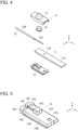
- FIG. 4 shows an assembly view of the connector.
- the connector includes a first insulator 14 and a second insulator 15, and these first and second insulators 14 and 15 constitute the housing 13.
- the sheet type conductive member 11 is disposed on the +Z direction side of the first insulator 14, and a conductor portion 12A exposed from an insulating coating portion 12B of the coated electric wire 12 is disposed on the +Z direction side of the sheet type conductive member 11.
- the conductor portion 12A of the coated electric wire 12 may be either of a so-called solid wire that is formed of one conductor and a so-called stranded wire that is formed by twisting a plurality of conductors.
- the connector includes a contact force-securing member 16.
- the contact force-securing member 16 is disposed on the +Z direction side of the conductor portion 12A of the coated electric wire 12, and the second insulator 15 is disposed on the +Z direction side of the contact force-securing member 16.
- FIGS. 5 to 7 show the first insulator 14.
- the first insulator 14 includes a flat plate portion 14A of substantially rectangular shape extending along an XY plane, and a +Z directional surface of the flat plate portion 14A forms a first retaining surface 14B extending along an XY plane and facing in +Z direction.
- the first retaining surface 14B is provided with a protrusion portion 14C of substantially prismatic shape protruding toward the +Z direction.
- the first retaining surface 14B is provided with a first conductor insertion groove 14D extending in the Y direction on the -Y direction side from the protrusion portion 14C, a first insulating coating insertion groove 14E communicating with a -Y directional end of the first conductor insertion groove 14D, and a first lead-out groove 14F communicating with a -Y directional end of the first insulating coating insertion groove 14E and extending up to an outer surface of a -Y directional end of the first insulator 14.
- the flat plate portion 14A includes three through-holes 14G separately formed on opposite sides of the first insulating coating insertion groove 14E in the X direction and near a +Y directional end of the flat plate portion 14A and penetrating the flat plate portion 14A in the Z direction.
- step portions 14H extending in the Y direction are separately formed at X-directional opposite lateral surfaces of the flat plate portion 14A.
- the first conductor insertion groove 14D, the first insulating coating insertion groove 14E, and the first lead-out groove 14F are formed coaxially with one another and have a common central axis CL.
- the first conductor insertion groove 14D has a groove width corresponding to the diameter of the conductor portion 12A of the coated electric wire 12, while the first insulating coating insertion groove 14E has a groove width corresponding to the outer diameter of the insulating coating portion 12B of the coated electric wire 12.
- the first lead-out groove 14F has the same groove width as that of the first insulating coating insertion groove 14E at its +Y directional end communicating with the first insulating coating insertion groove 14E, and has a shape with the groove width gradually increasing toward the -Y direction along the central axis CL.
- a projection 14J is formed to project from the bottom surface of the first insulating coating insertion groove 14E toward the inside of the first insulating coating insertion groove 14E in an XZ plane.
- the projection 14J has a semicircular shape when viewed in the Y direction along the central axis CL as shown in FIG. 9 , and has a projection height smaller than the thickness of the insulating coating portion 12B of the coated electric wire 12.
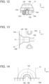
- FIGS. 10 to 12 shows the second insulator 15.
- the second insulator 15 includes a flat plate portion 15A of substantially rectangular shape extending along an XY plane, and a -Z directional surface of the flat plate portion 15A forms a second retaining surface 15B extending along an XY plane and facing in the -Z direction.
- a dome-shaped portion D is formed on the +Z direction side of the flat plate portion 15A to project from the flat plate portion 15A toward the +Z direction, and the second retaining surface 15B is provided with a recessed portion 15C extending to the inside of the dome-shaped portion D and opening toward the -Z direction.
- the second retaining surface 15B is provided with: a second conductor insertion groove 15D extending in the Y direction on the -Y direction side from the recessed portion 15C; a second insulating coating insertion groove 15E communicating with a -Y directional end of the second conductor insertion groove 15D; and a second lead-out groove 15F communicating with a -Y directional end of the second insulating coating insertion groove 15E and extending up to an outer surface of a -Y directional end of the second insulator 15.
- the flat plate portion 15A includes three bosses 15G separately formed on opposite sides of the second insulating coating insertion groove 15E in the X direction and near a +Y directional end of the flat plate portion 15A and projecting in the -Z direction.
- a pair of lateral plates 15H protruding in the -Z direction and extending in the Y direction are separately formed at X-directional opposite lateral portions of the flat plate portion 15A.
- the second conductor insertion groove 15D, the second insulating coating insertion groove 15E, and the second lead-out groove 15F are formed coaxially with one another and have the common central axis CL.
- the second conductor insertion groove 15D has a groove width corresponding to the diameter of the conductor portion 12A of the coated electric wire 12, while the second insulating coating insertion groove 15E has a groove width corresponding to the outer diameter of the insulating coating portion 12B of the coated electric wire 12.
- the second lead-out groove 15F has the same groove width as that of the second insulating coating insertion groove 15E at its +Y directional end communicating with the second insulating coating insertion groove 15E, and has a shape with the groove width gradually increasing toward the -Y direction along the central axis CL.
- the second insulating coating insertion groove 15E of the second insulator 15 is provided with no projection projecting from the bottom surface of the second insulating coating insertion groove 15E toward the inside of the second insulating coating insertion groove 15E.
- the first conductor insertion groove 14D of the first insulator 14 and the second conductor insertion groove 15D of the second insulator 15 are disposed to face each other to thereby retain the conductor portion 12A of the coated electric wire 12, and the first insulating coating insertion groove 14E of the first insulator 14 and the second insulating coating insertion groove 15E of the second insulator 15 are disposed to face each other to constitute an electric wire fixing portion of cylindrical shape that fastens an outer periphery of the insulating coating portion 12B of the coated electric wire 12 and fixes the coated electric wire 12.
- first lead-out groove 14F of the first insulator 14 and the second lead-out groove 15F of the second insulator 15 are disposed to face each other to constitute an electric wire lead-out port that leads out the coated electric wire 12 from the inside to the outside of the housing 13.
- the sheet type conductive member 11 is provided with a through-hole 11B corresponding to a +Y directional boss 15G on the second insulator 15.
- the contact force-securing member 16 shown in FIG. 4 is formed of a metal material and has a cylindrical shape.
- the contact force-securing member 16 is, when the connector is assembled, disposed between the recessed portion 15C of the second insulator 15 and the protrusion portion 14C of the first insulator 14 and secures the contact force between the conductor portion 12A of the coated electric wire 12 and the flexible conductor 11A of the sheet type conductive member 11 contacting each other.
- the contact force-securing member 16 is inserted into the recessed portion 15C of the second insulator 15 from the -Z direction, and the three bosses 15G of the second insulator 15 are separately inserted into the three through-holes 14G of the first insulator 14 with a +Y directional end of the coated electric wire 12 and a -Y directional end of the sheet type conductive member 11 being sandwiched between the first retaining surface 14B of the first insulator 14 and the second retaining surface 15B of the second insulator 15, whereby the first insulator 14 and the second insulator 15 are joined to each other.
- the first insulating coating insertion groove 14E of the first insulator 14 overlay the coated electric wire 12 so as to cover a -Z directional portion of the insulating coating portion 12B of the coated electric wire 12; however, since the first insulating coating insertion groove 14E is provided with the projection 14J projecting from the bottom surface of the first insulating coating insertion groove 14E toward the inside of the first insulating coating insertion groove 14E, the projection 14J bites into the -Z directional portion of the insulating coating portion 12B of the coated electric wire 12.
- the coated electric wire 12 is fixed to the housing 13 by means of the projection 14J biting into the -Z directional portion of the insulating coating portion 12B while being kept to be correctly positioned with respect to the second insulating coating insertion groove 15E of the second insulator 15, whereby the coated electric wire 12 is prevented from being pulled out from the housing 13.
- the three bosses 15G of the second insulator 15 separately penetrate the three through-holes 14G of the first insulator 14.
- the boss 15G situated on the +Y direction side among the three bosses 15G penetrates the corresponding through-hole 14G of the first insulator 14 through the through-hole 11B of the sheet type conductive member 11 shown in FIG. 4 .
- the pair of lateral plates 15H of the second insulator 15 are fitted in the pair of step portions 14H of the first insulator 14.
- Tips of the three bosses 15G projecting on the -Z direction side of the first insulator 14 are then thermally deformed, whereby the first insulator 14 and the second insulator 15 are fixed to each other to form the housing 13.
- the assembling operation of the connector is completed.
- FIG. 16 shows the inside of the connector assembled as above.
- the sheet type conductive member 11 and the conductor portion 12A of the coated electric wire 12 are inserted, by means of the protrusion portion 14C of the first insulator 14, in the inside of the contact force-securing member 16 disposed inside the recessed portion 15C of the second insulator 15 and deform to conform to a surface of the protrusion portion 14C.
- the conductor portion 12A of the coated electric wire 12 is sandwiched between the top surface of the sheet type conductive member 11 and the inner surface of the contact force-securing member 16, is brought into contact with the flexible conductor 11A exposed on the top surface of the sheet type conductive member 11 at a predetermined contact force, and is electrically connected to the flexible conductor 11A.
- the conductor portion 12A drawn in the +Y direction from the insulating coating portion 12B of the coated electric wire 12 is inserted in the first conductor insertion groove 14D of the first insulator 14 and the second conductor insertion groove 15D of the second insulator 15.
- the coated electric wire 12 is led out in the -Y direction from the electric wire lead-out port 13F formed by the first lead-out groove 14F of the first insulator 14 and the second lead-out groove 15F of the second insulator 15.
- the electric wire lead-out port 13F has a so-called horn shape gradually expanding from the electric wire fixing portion 13E of cylindrical shape toward the -Y direction along the central axis CL of the electric wire fixing portion 13E.
- the electric wire lead-out port 13F has a first contact portion S1 connected to the electric wire fixing portion 13E on the -Y direction side of the electric wire fixing portion 13E, a second contact portion S2 connected to the outer surface 13A on the -Y direction side of the housing 13, and a tapered portion S3 disposed between the first contact portion S1 and the second contact portion S2 and connecting the first contact portion S1 and the second contact portion S2 with each other.
- the first contact portion S1 when viewed from the -Y direction along the central axis CL of the electric wire fixing portion 13E, the first contact portion S1 has a circular ring shape surrounding the central axis CL at a position adjacent to the electric wire fixing portion 13E, and the second contact portion S2 has a circular ring shape surrounding the central axis CL in the vicinity of the outer surface 13A of the housing 13 and having a radius larger than that of the first contact portion S1.
- the first contact portion S1 and the second contact portion S2 each have such a curved shape as to protrude toward the central axis CL in a cross section passing the central axis CL of the electric wire fixing portion 13E.
- the tapered portion S3 disposed between the first contact portion S1 and the second contact portion S2 has a conical surface expanding toward the outer surface 13A of the housing 13, and is represented by a pair of line segments each inclined with respect to the central axis CL in FIG. 17 .
- the coated electric wire 12 is bent to contact the outer surface 13A of the housing 13 and extend toward the +Z direction along the outer surface 13A.
- the coated electric wire 12 is led out from the housing 13 at a predetermined minimum bending radius determined by the shape of the housing 13, specifically, the shape of the outer surface 13A, around the electric wire lead-out port 13F, and a tensile force is applied to the coated electric wire 12 from the +Z direction.
- the electric wire lead-out port 13F has the first contact portion S1 and the second contact portion S2, the electric wire lead-out port 13F contacts the coated electric wire 12 at each of a first contact point P1 situated on the first contact portion S1 and a second contact point P2 situated on the second contact portion S2, and does not contact and is situated away from the coated electric wire 12 at the tapered portion S3 between these first and second contact points P1 and P2.
- the electric wire lead-out port 13F contacts the coated electric wire 12 at each of the first contact portion S1 and the second contact portion S2 that are disposed at two positions separate from each other along the length direction of the coated electric wire 12, and the coated electric wire 12 is led out from the housing 13 at the predetermined minimum bending radius, whereby a load applied to the coated electric wire 12 is dispersed. Therefore, it is possible to prevent breakage of the conductor portion 12A of the coated electric wire 12 without using, for example, such a bendable bushing member made of a rubber or the like as that in the conventional cable protection device shown in FIG. 26 .
- the electric wire lead-out port 13F contacts the coated electric wire 12 at each of the first contact portion S1 and the second contact portion S2 that are disposed at two positions away from each other along the length direction of the coated electric wire 12, and loads applied to the coated electric wire 12 are dispersed, whereby breakage of the conductor portion 12A of the coated electric wire 12 is prevented.
- tapered portion S3 of the electric wire lead-out port 13F is not limited to one having a conical surface as long as it has a shape that does not contact the coated electric wire 12.
- first contact portion S1 and the second contact portion S2 of the electric wire lead-out port 13F each have such a curved shape as to protrude toward the central axis CL of the electric wire fixing portion 13E in the embodiment above, the invention is not limited thereto.
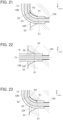
- a first contact portion S1 has such a curved shape as to protrude toward the central axis CL, but a second contact portion S2 has an angular shape. Even in the electric wire lead-out port 23F as above, as shown in FIG. 20 , a first contact portion S1 has such a curved shape as to protrude toward the central axis CL, but a second contact portion S2 has an angular shape. Even in the electric wire lead-out port 23F as above, as shown in FIG.
- the electric wire lead-out port 23F contacts the coated electric wire 12 at each of a first contact point P1 on the first contact portion S1 and a second contact point P2 on the second contact portion S2 that are disposed at two positions away from each other along the length direction of the coated electric wire 12, and a load applied to the coated electric wire 12 is dispersed, whereby breakage of the conductor portion 12A of the coated electric wire 12 can be prevented.
- a first contact portion S1 has an angular shape, while a second contact portion S2 has such a curved shape as to protrude toward the central axis CL.
- the electric wire lead-out port 33F contacts the coated electric wire 12 at each of a first contact point P1 on the first contact portion S1 and a second contact point P2 on the second contact portion S2 that are disposed at two positions away from each other along the length direction of the coated electric wire 12, and a load applied to the coated electric wire 12 is dispersed, whereby breakage of the conductor portion 12A of the coated electric wire 12 can be prevented.
- a first contact portion S1 and a second contact portion S2 both have an angular shape. Even in the electric wire lead-out port 43F as above, as shown in FIG. 24 , a first contact portion S1 and a second contact portion S2 both have an angular shape. Even in the electric wire lead-out port 43F as above, as shown in FIG. 24 , a first contact portion S1 and a second contact portion S2 both have an angular shape. Even in the electric wire lead-out port 43F as above, as shown in FIG.
- the electric wire lead-out port 43F contacts the coated electric wire 12 at each of a first contact point P1 on the first contact portion S1 and a second contact point P2 on the second contact portion S2 that are disposed at two positions away from each other along the length direction of the coated electric wire 12, and a load applied to the coated electric wire 12 is dispersed, whereby breakage of the conductor portion 12A of the coated electric wire 12 can be prevented.
- the connector of the embodiment When the connector of the embodiment is applied to smart clothes, and an electrode (not shown) is connected to the flexible conductor 11A of the sheet type conductive member 11, the electrode disposed at a measurement position and a wearable device can be connected to each other by means of the inexpensive coated electric wire 12 with low electric resistance.
- the contact force-securing member 16 is used to secure the contact force between the conductor portion 12A of the coated electric wire 12 and the flexible conductor 11A of the sheet type conductive member 11 contacting each other in the embodiment as above, it is possible to configure the connector in which the conductor portion 12A of the coated electric wire 12 and the flexible conductor 11A of the sheet type conductive member 11 are electrically connected with each other between the protrusion portion 14C of the first insulator 14 and the recessed portion 15C of the second insulator 15 without using the contact force-securing member 16.
Landscapes
- Details Of Connecting Devices For Male And Female Coupling (AREA)
- Coupling Device And Connection With Printed Circuit (AREA)
Claims (11)
- Connecteur reliant une partie conductrice (12A) d'un fil électrique (12) à un objet de connexion (11), le connecteur comprenant :un boîtier (13, 23, 33, 43) accueillant une extrémité de l'objet de connexion et une extrémité du fil électrique, dans lequel l'objet de connexion et la partie conductrice du fil électrique entrent en contact l'un avec l'autre et sont reliés électriquement l'un à l'autre dans le boîtier, le boîtier comporte un orifice de sortie de fil électrique (13F, 23F, 33F, 43F) faisant sortir le fil électrique depuis l'intérieur vers l'extérieur du boîtier,le connecteur étant caractérisé en ce que :
l'orifice de sortie de fil électrique comporte une première partie de contact (S1) et une seconde partie de contact (S2) qui entrent en contact avec le fil électrique au niveau d'un premier point de contact (P1) de la première partie de contact et d'un second point de contact (P2) de la seconde partie de contact séparés l'un de l'autre le long d'une direction longitudinale du fil électrique de façon à disperser une charge appliquée au fil électrique lorsque le fil électrique est sorti du boîtier à un rayon de courbure minimum prédéterminé, déterminé par une forme du boîtier autour de l'orifice de sortie de fil électrique, et dans lequel l'orifice de sortie de fil électrique est situé à l'écart du fil électrique (12) au niveau d'une partie conique (S3) entre les premier et deuxième points de contact (P1, P2). - Connecteur selon la revendication 1,dans lequel le fil électrique (12) inclut une partie de revêtement isolant (12B) recouvrant une périphérie externe de la partie conductrice,le boîtier (13, 23, 33, 43) comporte une partie de fixation de fil électrique (13E) de forme cylindrique qui est disposée à l'intérieur du boîtier et qui fixe le fil électrique en fixant la partie de revêtement isolant du fil électrique,l'orifice de sortie de fil électrique (13F, 23F, 33F, 43F) a une forme s'étendant depuis la partie de fixation de fil électrique le long d'un axe central (CL) de la forme cylindrique et s'étendant vers une surface externe du boîtier,la première partie de contact (S1) a une forme d'anneau circulaire entourant l'axe central au niveau d'une position adjacente à la partie de fixation de fil électrique, etla seconde partie de contact (S2) a une forme d'anneau circulaire entourant l'axe central au voisinage de la surface externe du boîtier et ayant un rayon plus grand que celui de la première partie de contact.
- Connecteur selon la revendication 2,dans lequel le boîtier est composé d'un premier isolant (14) ayant une première surface de retenue (14B) et d'un second isolant (15) ayant une seconde surface de retenue (15B) faisant face à la première surface de retenue et relié au premier isolant, etla partie de fixation de fil électrique (13E) et l'orifice de sortie de fil électrique (13F, 23F, 33F, 43F) sont formés par le premier isolant et le second isolant.
- Connecteur selon la revendication 3,dans lequel le premier isolant (14) inclut : une première rainure d'insertion de conducteur (14D) qui est formée dans la première surface de retenue et dans laquelle la partie conductrice du fil électrique est insérée ; une première rainure d'insertion de revêtement isolant (14E) qui est formée dans la première surface de retenue de manière à communiquer avec la première rainure d'insertion de conducteur et dans laquelle la partie de revêtement isolant du fil électrique est insérée ; et une première rainure de sortie (14F) formée dans la première surface de retenue de manière à communiquer avec la première rainure d'insertion de revêtement isolant,le second isolant (15) inclut : une seconde rainure d'insertion de conducteur (15D) qui est formée dans la seconde surface de retenue et dans laquelle la partie conductrice du fil électrique est insérée ; une seconde rainure d'insertion de revêtement isolant (15E) qui est formée dans la seconde surface de retenue de manière à communiquer avec la seconde rainure d'insertion de conducteur et dans laquelle la partie de revêtement isolant du fil électrique est insérée ; et une seconde rainure de sortie (15F) formée dans la seconde surface de retenue de manière à communiquer avec la seconde rainure d'insertion de revêtement isolant,la partie de fixation de fil électrique (13E) est formée par la première rainure d'insertion de revêtement isolant et la seconde rainure d'insertion de revêtement isolant disposées l'une en face de l'autre, etl'orifice de sortie de fil électrique (13F, 23F, 33F, 43F) est formé par la première rainure de sortie et la seconde rainure de sortie disposées l'une en face de l'autre.
- Connecteur selon la revendication 4, dans lequel une protubérance (14J) faisant saillie vers l'intérieur de la partie de fixation de fil électrique (13E) et mordant dans la partie de revêtement isolant (12B) du fil électrique est formée dans l'une ou l'autre de la première rainure d'insertion de revêtement isolant (14E) et la seconde rainure d'insertion de revêtement isolant (15E).
- Connecteur selon la revendication 5, dans lequel la protubérance (14J) a une forme semi-circulaire lorsqu'elle est vue dans une direction le long de l'axe central (CL).
- Connecteur selon l'une quelconque des revendications 2 à 6, dans lequel l'orifice de sortie de fil électrique (13F, 23F, 33F, 43F) possède une partie conique (S3) disposée entre la première partie de contact (S1) et la seconde partie de contact (S2) et constituée d'une surface conique s'étendant vers l'extérieur du boîtier (13, 23, 33, 43).
- Connecteur selon l'une quelconque des revendications 2 à 6, dans lequel au moins l'une parmi la première partie de contact (S1) et la seconde partie de contact (S2) a une forme incurvée dans une section transversale passant par l'axe central (CL).
- Connecteur selon l'une quelconque des revendications 2 à 6, dans lequel la première partie de contact (S1) et la seconde partie de contact (S2) ont toutes deux une forme angulaire dans une section transversale passant par l'axe central (CL).
- Connecteur selon l'une quelconque des revendications 3 à 6,dans lequel le premier isolant (14) inclut une partie protubérante (14C) formée pour faire saillie sur la première surface de retenue,le second isolant (15) inclut une partie évidée (15C) formée dans la seconde surface de retenue et correspondant à la partie protubérante,le premier isolant (14) et le second isolant (15) sont reliés l'un à l'autre avec l'objet de connexion et le fil électrique pris en sandwich entre la première surface de retenue et la seconde surface de retenue, etau moins une partie de la partie protubérante est logée dans la partie évidée, moyennant quoi la partie conductrice (12A) du fil électrique est reliée électriquement à l'objet de connexion (11) dans la partie évidée.
- Connecteur selon l'une quelconque des revendications 1 à 10, dans lequel un conducteur flexible (11 A) d'un élément conducteur de type feuille (11) est relié à la partie conductrice (12A) du fil électrique en tant qu'objet de connexion.
Applications Claiming Priority (1)
| Application Number | Priority Date | Filing Date | Title |
|---|---|---|---|
| JP2022200072A JP2024085525A (ja) | 2022-12-15 | 2022-12-15 | コネクタ |
Publications (2)
| Publication Number | Publication Date |
|---|---|
| EP4387004A1 EP4387004A1 (fr) | 2024-06-19 |
| EP4387004B1 true EP4387004B1 (fr) | 2025-02-12 |
Family
ID=88507129
Family Applications (1)
| Application Number | Title | Priority Date | Filing Date |
|---|---|---|---|
| EP23205538.4A Active EP4387004B1 (fr) | 2022-12-15 | 2023-10-24 | Connecteur |
Country Status (4)
| Country | Link |
|---|---|
| US (1) | US20240204450A1 (fr) |
| EP (1) | EP4387004B1 (fr) |
| JP (1) | JP2024085525A (fr) |
| CN (1) | CN118213778A (fr) |
Family Cites Families (5)
| Publication number | Priority date | Publication date | Assignee | Title |
|---|---|---|---|---|
| JPS58175678U (ja) * | 1982-05-19 | 1983-11-24 | 株式会社ナカヨ通信機 | 並行線保護構造 |
| US5151050A (en) * | 1991-09-30 | 1992-09-29 | Amp Incorporated | Cable assembly |
| JP4629276B2 (ja) * | 2001-07-16 | 2011-02-09 | 東洋電装株式会社 | レバースイッチ |
| EP2418745A1 (fr) * | 2010-08-09 | 2012-02-15 | Saint-Gobain Glass France | Boîtier de connexion de ligne électrique entre un film conducteur et un conducteur |
| JP6498862B2 (ja) * | 2013-12-11 | 2019-04-10 | 古河電気工業株式会社 | 電線接続構造、及び当該電線接続構造の製造方法 |
-
2022
- 2022-12-15 JP JP2022200072A patent/JP2024085525A/ja active Pending
-
2023
- 2023-10-10 CN CN202311313481.7A patent/CN118213778A/zh active Pending
- 2023-10-11 US US18/484,606 patent/US20240204450A1/en active Pending
- 2023-10-24 EP EP23205538.4A patent/EP4387004B1/fr active Active
Also Published As
| Publication number | Publication date |
|---|---|
| EP4387004A1 (fr) | 2024-06-19 |
| JP2024085525A (ja) | 2024-06-27 |
| CN118213778A (zh) | 2024-06-18 |
| US20240204450A1 (en) | 2024-06-20 |
Similar Documents
| Publication | Publication Date | Title |
|---|---|---|
| EP3376601B1 (fr) | Connecteur | |
| EP3435489B1 (fr) | Ensemble connecteur et carte de circuit imprimé | |
| EP4300713B1 (fr) | Élément conducteur de type feuille et connecteur | |
| JP2014026765A (ja) | コネクタ | |
| US20180219326A1 (en) | Floating connector and electronic device module | |
| EP4213308B1 (fr) | Connecteur | |
| EP4387004B1 (fr) | Connecteur | |
| US12230907B2 (en) | Electrical connector for connecting an electric wire to a flat flexible conductor and an electrical connector assembly therefor | |
| US20240088590A1 (en) | Connector | |
| JP5713217B2 (ja) | ケーブル接続方法 | |
| CN102138255A (zh) | 用于数字带的连接器、插座以及连接器组件 | |
| EP4346013B1 (fr) | Connecteur, ensemble connecteur et procédé de connexion | |
| US9780459B1 (en) | Linking cable connector | |
| EP4343974B1 (fr) | Connecteur | |
| EP4379964B1 (fr) | Ensemble connecteur et procédé de connexion | |
| JP2005285887A (ja) | 断線検知回路付回路基板 | |
| JP4381959B2 (ja) | ワイヤハーネス用ジョイントコネクタ及びその製造方法 | |
| EP4478554B1 (fr) | Connecteur et ensemble connecteur | |
| EP4228099B1 (fr) | Connecteur | |
| KR101053359B1 (ko) | 케이블 조립체 및 전자 배선 조립체 | |
| JPH0739136Y2 (ja) | フラットワイヤハーネスの分岐接続構造 | |
| TWM620948U (zh) | 夾線連接器組件 | |
| JP2007207628A (ja) | 電気接続箱 |
Legal Events
| Date | Code | Title | Description |
|---|---|---|---|
| PUAI | Public reference made under article 153(3) epc to a published international application that has entered the european phase |
Free format text: ORIGINAL CODE: 0009012 |
|
| STAA | Information on the status of an ep patent application or granted ep patent |
Free format text: STATUS: REQUEST FOR EXAMINATION WAS MADE |
|
| 17P | Request for examination filed |
Effective date: 20231024 |
|
| AK | Designated contracting states |
Kind code of ref document: A1 Designated state(s): AL AT BE BG CH CY CZ DE DK EE ES FI FR GB GR HR HU IE IS IT LI LT LU LV MC ME MK MT NL NO PL PT RO RS SE SI SK SM TR |
|
| RBV | Designated contracting states (corrected) |
Designated state(s): AL AT BE BG CH CY CZ DE DK EE ES FI FR GB GR HR HU IE IS IT LI LT LU LV MC ME MK MT NL NO PL PT RO RS SE SI SK SM TR |
|
| GRAP | Despatch of communication of intention to grant a patent |
Free format text: ORIGINAL CODE: EPIDOSNIGR1 |
|
| STAA | Information on the status of an ep patent application or granted ep patent |
Free format text: STATUS: GRANT OF PATENT IS INTENDED |
|
| INTG | Intention to grant announced |
Effective date: 20240924 |
|
| RAP3 | Party data changed (applicant data changed or rights of an application transferred) |
Owner name: JAPAN AVIATION ELECTRONICS INDUSTRY, LIMITED |
|
| GRAS | Grant fee paid |
Free format text: ORIGINAL CODE: EPIDOSNIGR3 |
|
| GRAA | (expected) grant |
Free format text: ORIGINAL CODE: 0009210 |
|
| STAA | Information on the status of an ep patent application or granted ep patent |
Free format text: STATUS: THE PATENT HAS BEEN GRANTED |
|
| AK | Designated contracting states |
Kind code of ref document: B1 Designated state(s): AL AT BE BG CH CY CZ DE DK EE ES FI FR GB GR HR HU IE IS IT LI LT LU LV MC ME MK MT NL NO PL PT RO RS SE SI SK SM TR |
|
| REG | Reference to a national code |
Ref country code: GB Ref legal event code: FG4D |
|
| REG | Reference to a national code |
Ref country code: CH Ref legal event code: EP |
|
| REG | Reference to a national code |
Ref country code: DE Ref legal event code: R096 Ref document number: 602023002015 Country of ref document: DE |
|
| REG | Reference to a national code |
Ref country code: IE Ref legal event code: FG4D |
|
| REG | Reference to a national code |
Ref country code: NL Ref legal event code: MP Effective date: 20250212 |
|
| PG25 | Lapsed in a contracting state [announced via postgrant information from national office to epo] |
Ref country code: RS Free format text: LAPSE BECAUSE OF FAILURE TO SUBMIT A TRANSLATION OF THE DESCRIPTION OR TO PAY THE FEE WITHIN THE PRESCRIBED TIME-LIMIT Effective date: 20250512 |
|
| PG25 | Lapsed in a contracting state [announced via postgrant information from national office to epo] |
Ref country code: FI Free format text: LAPSE BECAUSE OF FAILURE TO SUBMIT A TRANSLATION OF THE DESCRIPTION OR TO PAY THE FEE WITHIN THE PRESCRIBED TIME-LIMIT Effective date: 20250212 |
|
| PG25 | Lapsed in a contracting state [announced via postgrant information from national office to epo] |
Ref country code: PL Free format text: LAPSE BECAUSE OF FAILURE TO SUBMIT A TRANSLATION OF THE DESCRIPTION OR TO PAY THE FEE WITHIN THE PRESCRIBED TIME-LIMIT Effective date: 20250212 |
|
| PG25 | Lapsed in a contracting state [announced via postgrant information from national office to epo] |
Ref country code: ES Free format text: LAPSE BECAUSE OF FAILURE TO SUBMIT A TRANSLATION OF THE DESCRIPTION OR TO PAY THE FEE WITHIN THE PRESCRIBED TIME-LIMIT Effective date: 20250212 |
|
| REG | Reference to a national code |
Ref country code: LT Ref legal event code: MG9D |
|
| PG25 | Lapsed in a contracting state [announced via postgrant information from national office to epo] |
Ref country code: IS Free format text: LAPSE BECAUSE OF FAILURE TO SUBMIT A TRANSLATION OF THE DESCRIPTION OR TO PAY THE FEE WITHIN THE PRESCRIBED TIME-LIMIT Effective date: 20250612 Ref country code: NO Free format text: LAPSE BECAUSE OF FAILURE TO SUBMIT A TRANSLATION OF THE DESCRIPTION OR TO PAY THE FEE WITHIN THE PRESCRIBED TIME-LIMIT Effective date: 20250512 |
|
| PG25 | Lapsed in a contracting state [announced via postgrant information from national office to epo] |
Ref country code: NL Free format text: LAPSE BECAUSE OF FAILURE TO SUBMIT A TRANSLATION OF THE DESCRIPTION OR TO PAY THE FEE WITHIN THE PRESCRIBED TIME-LIMIT Effective date: 20250212 |
|
| PG25 | Lapsed in a contracting state [announced via postgrant information from national office to epo] |
Ref country code: HR Free format text: LAPSE BECAUSE OF FAILURE TO SUBMIT A TRANSLATION OF THE DESCRIPTION OR TO PAY THE FEE WITHIN THE PRESCRIBED TIME-LIMIT Effective date: 20250212 |
|
| PG25 | Lapsed in a contracting state [announced via postgrant information from national office to epo] |
Ref country code: PT Free format text: LAPSE BECAUSE OF FAILURE TO SUBMIT A TRANSLATION OF THE DESCRIPTION OR TO PAY THE FEE WITHIN THE PRESCRIBED TIME-LIMIT Effective date: 20250612 Ref country code: LV Free format text: LAPSE BECAUSE OF FAILURE TO SUBMIT A TRANSLATION OF THE DESCRIPTION OR TO PAY THE FEE WITHIN THE PRESCRIBED TIME-LIMIT Effective date: 20250212 |
|
| PG25 | Lapsed in a contracting state [announced via postgrant information from national office to epo] |
Ref country code: BG Free format text: LAPSE BECAUSE OF FAILURE TO SUBMIT A TRANSLATION OF THE DESCRIPTION OR TO PAY THE FEE WITHIN THE PRESCRIBED TIME-LIMIT Effective date: 20250212 Ref country code: GR Free format text: LAPSE BECAUSE OF FAILURE TO SUBMIT A TRANSLATION OF THE DESCRIPTION OR TO PAY THE FEE WITHIN THE PRESCRIBED TIME-LIMIT Effective date: 20250513 |
|
| PG25 | Lapsed in a contracting state [announced via postgrant information from national office to epo] |
Ref country code: SE Free format text: LAPSE BECAUSE OF FAILURE TO SUBMIT A TRANSLATION OF THE DESCRIPTION OR TO PAY THE FEE WITHIN THE PRESCRIBED TIME-LIMIT Effective date: 20250212 |
|
| PG25 | Lapsed in a contracting state [announced via postgrant information from national office to epo] |
Ref country code: SM Free format text: LAPSE BECAUSE OF FAILURE TO SUBMIT A TRANSLATION OF THE DESCRIPTION OR TO PAY THE FEE WITHIN THE PRESCRIBED TIME-LIMIT Effective date: 20250212 |
|
| PG25 | Lapsed in a contracting state [announced via postgrant information from national office to epo] |
Ref country code: DK Free format text: LAPSE BECAUSE OF FAILURE TO SUBMIT A TRANSLATION OF THE DESCRIPTION OR TO PAY THE FEE WITHIN THE PRESCRIBED TIME-LIMIT Effective date: 20250212 |
|
| PG25 | Lapsed in a contracting state [announced via postgrant information from national office to epo] |
Ref country code: IT Free format text: LAPSE BECAUSE OF FAILURE TO SUBMIT A TRANSLATION OF THE DESCRIPTION OR TO PAY THE FEE WITHIN THE PRESCRIBED TIME-LIMIT Effective date: 20250212 |
|
| PG25 | Lapsed in a contracting state [announced via postgrant information from national office to epo] |
Ref country code: AT Free format text: LAPSE BECAUSE OF FAILURE TO SUBMIT A TRANSLATION OF THE DESCRIPTION OR TO PAY THE FEE WITHIN THE PRESCRIBED TIME-LIMIT Effective date: 20250212 |
|
| PGFP | Annual fee paid to national office [announced via postgrant information from national office to epo] |
Ref country code: FR Payment date: 20250908 Year of fee payment: 3 |
|
| PG25 | Lapsed in a contracting state [announced via postgrant information from national office to epo] |
Ref country code: EE Free format text: LAPSE BECAUSE OF FAILURE TO SUBMIT A TRANSLATION OF THE DESCRIPTION OR TO PAY THE FEE WITHIN THE PRESCRIBED TIME-LIMIT Effective date: 20250212 Ref country code: CZ Free format text: LAPSE BECAUSE OF FAILURE TO SUBMIT A TRANSLATION OF THE DESCRIPTION OR TO PAY THE FEE WITHIN THE PRESCRIBED TIME-LIMIT Effective date: 20250212 |
|
| PG25 | Lapsed in a contracting state [announced via postgrant information from national office to epo] |
Ref country code: RO Free format text: LAPSE BECAUSE OF FAILURE TO SUBMIT A TRANSLATION OF THE DESCRIPTION OR TO PAY THE FEE WITHIN THE PRESCRIBED TIME-LIMIT Effective date: 20250212 |
|
| PG25 | Lapsed in a contracting state [announced via postgrant information from national office to epo] |
Ref country code: SK Free format text: LAPSE BECAUSE OF FAILURE TO SUBMIT A TRANSLATION OF THE DESCRIPTION OR TO PAY THE FEE WITHIN THE PRESCRIBED TIME-LIMIT Effective date: 20250212 |
|
| REG | Reference to a national code |
Ref country code: DE Ref legal event code: R097 Ref document number: 602023002015 Country of ref document: DE |
|
| PLBE | No opposition filed within time limit |
Free format text: ORIGINAL CODE: 0009261 |
|
| STAA | Information on the status of an ep patent application or granted ep patent |
Free format text: STATUS: NO OPPOSITION FILED WITHIN TIME LIMIT |
|
| PGFP | Annual fee paid to national office [announced via postgrant information from national office to epo] |
Ref country code: DE Payment date: 20250902 Year of fee payment: 3 |
|
| 26N | No opposition filed |
Effective date: 20251113 |