EP4387769B1 - Centrifugeuse - Google Patents
Centrifugeuse Download PDFInfo
- Publication number
- EP4387769B1 EP4387769B1 EP22765523.0A EP22765523A EP4387769B1 EP 4387769 B1 EP4387769 B1 EP 4387769B1 EP 22765523 A EP22765523 A EP 22765523A EP 4387769 B1 EP4387769 B1 EP 4387769B1
- Authority
- EP
- European Patent Office
- Prior art keywords
- adapter
- locking
- angle
- rotor
- centrifuge according
- Prior art date
- Legal status (The legal status is an assumption and is not a legal conclusion. Google has not performed a legal analysis and makes no representation as to the accuracy of the status listed.)
- Active
Links
Images



Classifications
-
- B—PERFORMING OPERATIONS; TRANSPORTING
- B04—CENTRIFUGAL APPARATUS OR MACHINES FOR CARRYING-OUT PHYSICAL OR CHEMICAL PROCESSES
- B04B—CENTRIFUGES
- B04B9/00—Drives specially designed for centrifuges; Arrangement or disposition of transmission gearing; Suspending or balancing rotary bowls
- B04B9/08—Arrangement or disposition of transmission gearing ; Couplings; Brakes
-
- B—PERFORMING OPERATIONS; TRANSPORTING
- B04—CENTRIFUGAL APPARATUS OR MACHINES FOR CARRYING-OUT PHYSICAL OR CHEMICAL PROCESSES
- B04B—CENTRIFUGES
- B04B9/00—Drives specially designed for centrifuges; Arrangement or disposition of transmission gearing; Suspending or balancing rotary bowls
- B04B9/08—Arrangement or disposition of transmission gearing ; Couplings; Brakes
- B04B2009/085—Locking means between drive shaft and rotor
Definitions
- the invention relates to a centrifuge according to the type specified in the preamble of claim 1.
- Centrifuges with a removable rotor which have a device for axial locking and rotationally fixed connection of the rotor to the drive shaft or an adapter arranged on the drive shaft, where no complex assembly or special tools are required for locking.
- a centrifuge is from the DE 10 2018 114 289 A1
- This centrifuge has a drive shaft that can rotate about a rotational axis.
- An adapter is connected to the drive shaft in a rotationally fixed manner.
- the adapter can be detached from the drive shaft as needed.
- the adapter can also be part of the drive shaft.
- a rotor that can be axially removed in a removal direction is provided on the adapter and is connected to the adapter via a one-handed quick-release fastener that acts between the rotor and the adapter.
- the quick-release fastener allows the rotor to be fixed relative to the adapter and thus also relative to the drive shaft in the removal direction and can be released as needed, for example to load the rotor with samples outside the centrifuge or to insert another rotor for different sample containers into the centrifuge.
- the adapter is provided with an abutment, and the rotor with a locking bearing.
- at least one locking element is provided as part of the quick-release fastener. When activated, this locking element fixes the rotor relative to the adapter and thus to the drive shaft and acts between the locking bearing of the rotor and the abutment of the drive shaft.
- the quick-release fastener has an actuating element, via which the locking elements can be transferred from the unlocked position to a locked position and vice versa.
- the locking element is operatively connected to the actuating element in such a way that the actuating element can be moved between an unlocked position and a locked position linearly, in particular parallel to the axis of rotation of the
- the drive shaft is movably mounted.
- the locking element performs a linear movement relative to the adapter when the actuating element moves between the unlocking and locking positions.
- a centrifuge is also known in which the locking elements are rotated from an unlocking position to a locking position about an axis parallel to the axis of rotation of the drive shaft.
- the pivoting of the locking elements proves to be disadvantageous. If the system is subject to tolerances, with a height tolerance in the axial direction being particularly important, the locking elements can no longer be in full contact with the locking bearing, but only in specific points. This leads to high material stress in some areas.
- Another problem with this design is that the locking elements are exposed to high loads during rotation. Due to the horizontal arrangement and the locking elements being movable in the horizontal plane, the centrifugal forces act on them almost unhindered. In many cases, the locking elements jam with the rotor, making it impossible to release the quick-release fastener and thus the locking elements. The rotor can then no longer be easily removed from the adapter or the drive shaft.
- a generic centrifuge is from the DE 10 2014 002 126 A1 known. This has a quick-release fastener for a rotor that is provided with a bearing axis on which the locking element is mounted so that it can be axially displaced. A spring presses the locking element into the extended position, the locking position. A locking surface of the locking bearing is aligned horizontally and has an angle between the axis of rotation and the locking surface of 90°. The bearing axis on which the locking element is moved has an angle of 95° to 120°, preferably 100° to 110°, in particular 100° to 107°.
- the locking element is shaped in such a way that the downward-facing front part of the locking element, which is assigned to the locking surface of the rotor, is moved horizontally during unlocking and locking.
- the disadvantage of this design is that the forces occurring during centrifugation can cause the locking element to jam. The quick-release fastener is then blocked and can no longer be operated.
- the surfaces of the locking element, the bearing axis, and the locking surface must be precisely machined.
- the shape of the locking elements is very complex. Tolerance compensation is not possible.
- the manufacturing is not precise, the rotor and adapter may be subject to play.
- the invention is based on the object of developing a centrifuge according to the type specified in the preamble of patent claim 1 in such a way that, while avoiding the disadvantages mentioned, both a play-free locking between the rotor and the adapter is made possible by means of the locking elements and a compensation of manufacturing-related tolerances is ensured.
- the invention is based on the finding that by arranging the locking element at a first angle to the rotational axis of the drive shaft and by designing the rotor's locking bearing at a second angle to the rotational axis, the manufacturing tolerances of the rotor, the adapter, and the drive shaft can be compensated for, while still achieving a play-free locking of the rotor relative to the adapter and the drive shaft.
- the locking element thus rests more or less radially on the locking bearing.
- the locking element is therefore linearly movable at a first angle to the axis of rotation between the locking position and the unlocking position.
- the locking bearing is aligned at a second angle to the axis of rotation, which is different from the first angle.
- the first and second angles are measured primarily from the axis of rotation of the drive shaft clockwise from the side of the actuating element and lie between 0° and 90°.
- the different design of the two angles prevents the locking element from jamming and also ensures easy release of the quick-release fastener from the locking position to the unlocking position.
- This also creates the conditions for compensating manufacturing tolerances of the drive shaft, adapter and rotor in a simple manner, particularly in the direction of the axis of rotation. For example, play-free locking is then possible despite existing manufacturing tolerances, since the locking element engages more or less in the locking bearing depending on the tolerance.
- the first angle is in a range of 20° to 75° and the second angle is in a range of 10° to 70°.
- the first angle is used, among other things, to adjust the force acting on the locking element during operation of the centrifuge, i.e. during rotation. The larger the The higher the angle, the greater the centrifugal forces acting on the locking element.
- the second angle adjusts the extended position of the locking element to compensate for tolerances.
- the first angle is larger than the second angle.
- the smaller the second angle the smaller the difference in the position of the locking element with a given tolerance compared to a design without tolerance in the locked position.
- the larger the second angle the greater the difference in the position of the locking element with a given tolerance compared to a design without tolerance in the locked position.
- the locking bearing forms a surface which, in the locking position, extends to the adapter, wherein the surface of the locking bearing in the adapter in the locking position has a height offset from the blocking element protruding from the adapter, so that the blocking element rests against the locking bearing in the locking position at a radial distance from the adapter.
- the height offset is greater than the maximum possible manufacturing tolerance of the adjacent surfaces of the adapter and rotor in a direction parallel to the axis of rotation. This prevents the locking element from being unable to sufficiently penetrate the locking bearing when the rotor is locked to the adapter, or in the worst case, from being blocked and unable to penetrate the locking bearing at all.
- the actuating element is designed as a cylindrical pin.
- the lower portion of the actuating element has a receptacle for the locking element(s). The movement of the actuating element can thus be easily transferred to the locking elements.
- the actuating element has laterally U-shaped recesses for the locking elements, which enable a relative movement of the actuating element with respect to the respective locking element between a locking position and an unlocking position.
- the U-shaped recess can be formed in the transverse region as an oblique bore which extends at a first angle to the axis of rotation.
- the possibilities for transmitting force from a spring to the actuating element and the locking elements are increased by providing a pressure plate on the side of the actuating element associated with the drive shaft.
- This pressure plate has a first contact surface for the respective locking element on one side of the pressure plate and a second contact surface for a spring on the other side of the pressure plate.
- the locking elements can slide along the first contact surface when moving between the locking position and the unlocking position to compensate for their relative position to the actuating element.
- the first contact surface of the pressure plate for the respective locking element can be aligned at an angle which is arranged perpendicular to the first angle.
- the locking element can be in contact with the locking bearing in a point-like manner, particularly at two points, in a linear manner or over a flat area.
- the adapter has a guide surface for the locking element that is inclined at a first angle. This guide surface enables the locking element to move linearly in and out with respect to the adapter, i.e., to move the locking element between the locking position and the unlocking position.
- the abutment can also be part of the adapter and, in particular, can also be aligned at the first angle.
- the guide surface and abutment can be identical.
- the actuating element and/or the locking element are spring-loaded towards the locking position.
- the locking elements are arranged at an equal distance from each other.
- the locking element is designed as an elongated pin, which, particularly in its basic shape, is almost entirely cylindrical. This ensures simple, cost-effective, and process-reliable production of the locking elements by turning with high dimensional accuracy within narrow tolerances. This also allows the corresponding surfaces in the adapter and rotor to be manufactured simply and cost-effectively.
- the locking element In order to prevent the locking element from twisting when moving from the locking position to the unlocking position and vice versa, the locking element has recesses which interact with projections on the adapter to prevent twisting.
- the locking element is provided with a bevel at its front end, which rests against the locking bearing in the locked position. This creates two support points per locking element, halving the force at the support point for the locking element. This further reduces the risk of jamming, and the bevel also allows the position of the locking element to be adjusted within certain manufacturing tolerances.
- the locking element is provided with a chamfer at its front end, which is designed so that, in the locked position with the rotor mounted on the adapter, it runs parallel to the locking bearing.
- the locking element can be designed as a simple turned part. This achieves a linear contact. This also very easily reduces the risk of jamming.
- the bevel is designed to be identical to the conical surface of the locking bearing. This ensures that the locking elements rest flat against the locking bearing even with different height tolerances, further reducing the risk of jamming.
- the conical surfaces of the locking bearing can be manufactured using simple, cost-effective, and reliable turning with high dimensional accuracy within tight tolerances.
- the locking element is mounted in the adapter in such a way that the longitudinal axis of the locking element intersects the axis of rotation.
- three locking elements are provided, whereby the forces occurring during operation are well distributed and a secure connection between the adapter and the rotor is achieved.
- the inventive design guides the locking elements within the adapter.
- the locking element guidance is coordinated within narrow tolerances, thus easily preventing jamming.
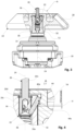
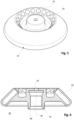
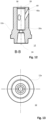
- FIG. 1 to 17 A first embodiment of a laboratory centrifuge is shown in various views.
- the centrifuge comprises a rotor 10, which is mounted on a drive shaft 14 via an adapter 12.
- the drive motor 18 drives the rotor 10 via the drive shaft 14 and the adapter 12.
- the adapter 12 is connected to the drive shaft 14 in a rotationally fixed manner and is fixed in the axial direction relative to the drive shaft 14.
- the rotor 10 is a conventional rotor 10 with inclined sample container holders 20 for sample containers not shown here.
- the rotor 10 is connected to the adapter 12 via a quick-release fastener 22.
- the quick-release fastener 22 secures the rotor 10 to the adapter 12 in the axial direction and in both directions about a rotational axis 24 of the drive shaft 14.
- the quick-release fastener 22 has an actuating element 26, which protrudes from the top of the adapter 12 and the rotor 10 and forms a push button 26a.
- the adapter 12 is provided with a bore 28 arranged concentrically to the rotational axis 24 of the drive shaft 14, into which a stop ring 30 is inserted at the upper end of the adapter.
- the stop ring 30 limits the axial upward movement of the actuating element 26, see Fig. 2 to Fig. 4 .
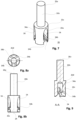
- the upper portion 26b of the actuating element 26 is cylindrical in shape. This is followed by a widened, lower cylindrical portion 26c, which has a concentric, downwardly open bore 26d, see Fig. 7 to Fig. 9
- the lower portion 26c is provided with three U-shaped lateral recesses 34, which are assigned to the three locking elements 32.
- the transverse portion 34a of the U-shaped recess 34 is designed as an oblique bore. The angle of the oblique bore corresponds to a first angle ⁇ .
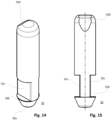
- a projection 34b is provided on each side. Both lateral projections 34b engage from each side into a recess 32b of the locking element 32, see Fig. 14 and Fig. 15 .
- the recess 32b of the locking element 32 is designed such that a relative movement can take place between the locking element 32 and the actuating element 26, and the projections 34b and the recess 32b serve as a guide for this relative movement.
- a pressure plate 36 which has a conical surface 36a on the side facing the bore 26d, on which the locking elements 32 are mounted at their lower area.
- the conical surface 36a i.e. the cone formed thereby, runs perpendicular to the longitudinal axis of the locking element 32 and thus perpendicular to the first angle ⁇ .
- the locking elements 32 move along the conical surface during the movement from the locking position to the unlocking position and vice versa.
- a spring 38 bears against a second contact surface of the pressure plate 36, which is remote from the first contact surface and which is supported on a shoulder 28a in the bore 28 of the adapter 12 and prestresses the actuating element 26 and the locking elements 32 upwards in the direction of a locking position.
- the adapter 12 is designed in the manner of a turned part, i.e., rotationally symmetrical.
- the adapter 12 is provided with three oblique bores 40, wherein the bores 40 are introduced into the adapter 12 at a first angle ⁇ and are spaced equally apart from one another.
- a locking element 32 is guided through each bore 40, which is cylindrical and adapted to the bore 40 such that it can be moved linearly along a longitudinal axis 42 of the bore 40, which is aligned at the first angle ⁇ , between an unlocking position, see Fig. 2 , and a locking position, see Fig. 3 , is displaceable.
- the inner surface of the bore 40 in the adapter 12 serves as a guide surface.
- the guide surface also forms an abutment 40a for the locking element 32 in the locking position.
- the adapter 12 is provided with a conical area on the outside, which serves as a support 12a for the rotor 10.
- the rotor 10 is fixed downwards in the axial direction via the support 12a.
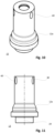
- the locking element 32 is designed as a cylindrical pin.
- the lower end of the locking element is provided with a cone 32a.
- a recess 32b is formed on each side of the cone 32a, resulting in a rectangular, flat shape, which forms two parallel guide surfaces 32c.
- the upper portion of the locking element 32 is rounded and, on the side rotated 90° relative to the guide surfaces 32c, has an upper conical clamping surface 32d, which rests flush against an associated surface of a locking bearing 44 of the rotor 10.
- the remaining upper portion of the locking element 32 is rounded.
- the basic shape of the locking element is cylindrical and rotationally symmetrical.
- An alternative locking element 32 is Fig. 18 and Fig. 19
- a rotationally symmetrical recess 32e concentric to the longitudinal axis of the locking element, is inserted, for example, screwed in, adjacent to the cone 32b.
- the height of the recess 32e corresponds to the height of the recess 32b.
- the locking bearing 44 extends at a second angle ⁇ .
- the first angle ⁇ is greater than the second angle ⁇ .
- the surface 44a of the locking bearing 44 extends, see Fig. 4 , to below the hole 40 in the adapter 12. This results in a height offset H, see Fig. 4 , via which the manufacturing tolerances - height tolerance, mainly caused by two cones 52, 54, a first cone 52 between rotor 10 and adapter 12, a second cone 54 between adapter 12 and rotor 10 - along the axis of rotation 24 of the drive shaft 14 can be compensated.
- the locking bearing 44 is a conical surface 44a which is aligned at the second angle ⁇ .
- the height offset H is in any case greater than the maximum possible manufacturing tolerance of the adjacent surfaces of drive shaft 14, adapter 12 and rotor 10 in a direction parallel to the axis of rotation. Due to the height offset H, the locking element 32 comes to rest on the locking bearing 44 in the locked position at a radial distance from the adapter 12.
- Both the first angle ⁇ , at which, for example, the guide surface and the abutment 40a of the bore 40 are aligned, and the second angle ⁇ , at which the locking bearing 44 is aligned, are measured from the rotation axis 24 at the top in a clockwise direction to the abutment 40a and the locking bearing 44.
- the first angle ⁇ is greater than the second angle ⁇ .
- the first angle ⁇ lies between 0° and 90°, in particular 30°.
- the second angle ⁇ also lies between 0° and 90°, in particular 20°.
- the locking elements 32 are arranged at equal spacing from one another. Accordingly, the bores 40 and the U-shaped recesses 34 are also arranged at equal spacing from one another. Each locking element 32 is associated with a U-shaped recess 34 and a bore 40 in the adapter 12. The two lateral projections 34b of a U-shaped recess 34 engage with the recess 32b of the locking element 32.
- the recess 32c in cooperation with the lateral projections 34b in the U-shaped recess 34 form an anti-twist device for the locking element 32.
- the Locking element 32 does not move during linear movement from the unlocking position to the locking position.
- the rotor has a rotor bore 46 arranged concentrically to the axis of rotation 24, which has a conical region 48 at its free end.
- the conical region 48 is the rotor-side counterbearing for the support 12a of the adapter 12.
- the rotor bore 46 is open at the bottom so that the rotor 10 can be placed on the adapter 12 and the adapter 12 can engage with the rotor 10.
- a through-bore 50 is provided, through which the actuating element 26 with its push button 26a protrudes when the rotor 10 is mounted. Otherwise, the rotor 10 is provided in a conventional manner with the sample container receptacles 20 for sample containers not shown here.
- a set of different rotors 10 is provided, which can accommodate different sample container shapes.
- the area of the rotor bore 46 with the through-bore 50 and the locking bearing 44 is always constructed the same.
- the push button 26a of the actuating element 26 is moved from the locking position, see Fig. 3 and Fig. 4 , pressed down into the unlocking position, see Fig. 2 .
- the actuating element 26 and the pressure plate 36 move linearly downwards against the force of the spring 38 and thus also the locking elements 32.
- Each locking element 32 is moved linearly obliquely downwards at the first angle ⁇ until the locking element 32 is completely arranged in the adapter 12 and the upper region of the locking element is within the bore 40.
- the locking element 32 no longer blocks the rotor 10 from being pulled upwards away from the adapter 12.
- the contact point of the locking element 32 on the conical surface 36a of the pressure plate 36 moves linearly in one direction or the other, depending on whether the locking element 32 is moved out of the adapter 12 or retracted.
- the rotor 10 is then firmly connected again to the adapter 12 and, above this, to the drive shaft 14. Should manufacturing tolerances occur, the locking bearing 44 will be higher or lower. The locking element 32 will therefore move more or less into the locking bearing 44. In any case, there is a play-free frictional connection between the locking bearing 44, the locking element 32 and the abutment 40a in the bore 40 of the adapter 12. A secure arrangement of the rotor 10 on the adapter 12 and thus on the drive shaft 14 is thereby ensured.
Landscapes
- Centrifugal Separators (AREA)
Claims (15)
- Centrifugeuse, présentant un arbre d'entraînement (14) pouvant tourner autour d'un axe de rotation (24), un adaptateur (12) relié à l'arbre d'entraînement (14) ou formant une partie de l'arbre d'entraînement (14), un rotor (10) monté sur l'adaptateur (12), pouvant être retiré axialement dans une direction de prélèvement, une fermeture rapide (22) agissant entre le rotor (10) et l'adaptateur (12), au moyen de laquelle le rotor (10) peut être fixé par rapport à l'adaptateur (12) dans la direction de prélèvement et peut être détaché si besoin est, une butée (40a) reliée à l'adaptateur (12), un palier de verrouillage (44) relié au rotor (10), au moins un élément de blocage (32) comme partie de la fermeture rapide (22), lequel lors de son activation immobilise le rotor (10) par rapport à l'adaptateur (12) et ainsi par rapport à l'arbre d'entraînement (14) et agit entre le palier de verrouillage (44) du rotor (10) et la butée (40a) de l'arbre d'entraînement (14), dans laquelle la fermeture rapide (22) présente un élément d'actionnement (26) et l'élément de blocage (32) est en liaison fonctionnelle avec l'élément d'actionnement (26), de sorte que l'élément d'actionnement (26) est monté mobile linéairement entre une position de déverrouillage et une position de verrouillage, en particulier parallèlement, par rapport à l'axe de rotation (24) de l'arbre d'entraînement (14), l'élément de blocage (32) lors du déplacement de l'élément d'actionnement (26) effectue un mouvement linéaire par rapport à l'adaptateur (12), l'élément de blocage (32) est mobile à un premier angle (α) par rapport à l'axe de rotation (24) entre la position de verrouillage et la position de déverrouillage, et le palier de verrouillage (44) est orienté par rapport à l'axe de rotation (24) à un deuxième angle (β), qui est différent du premier angle (α), caractérisée en ce que les angles (α, β) sont mesurés à partir de l'axe de rotation (24) dans le sens horaire à partir du côté de l'élément d'actionnement (26) et sont compris entre 0° et 90°.
- Centrifugeuse selon la revendication 1, caractérisée en ce que le premier angle (α) se situe dans une plage de 20° à 75° et le deuxième angle (β) dans une plage de 10° à 70°.
- Centrifugeuse selon la revendication 1 ou 2, caractérisée en ce que le premier angle (α) est plus grand que le deuxième angle (β).
- Centrifugeuse selon l'une quelconque des revendications précédentes, caractérisée en ce que le palier de verrouillage (44) forme une surface (44a) qui dans la position de verrouillage s'étend jusqu'à l'adaptateur (12), dans laquelle la surface (44a) du palier de verrouillage (44) lorsque l'adaptateur (12) est dans la position de verrouillage présente un décalage en hauteur (H) par rapport à l'élément de blocage (32) faisant saillie de l'adaptateur (12), de sorte que l'élément de blocage (32) à distance radiale de l'adaptateur (12) s'applique sur le palier de verrouillage (44), de préférence le décalage en hauteur (H) est plus grand que la tolérance de fabrication maximale possible des surfaces de l'adaptateur (12) et du rotor (10) juxtaposées dans une direction parallèle à l'axe de rotation (24).
- Centrifugeuse selon l'une quelconque des revendications précédentes, caractérisée en ce que l'élément d'actionnement (26) est réalisé comme une tige cylindrique et présente dans la zone inférieure un logement pour l'élément de blocage (32) ou pour les éléments de blocage (32).
- Centrifugeuse selon la revendication 6, caractérisée en ce que l'élément d'actionnement (26) présente latéralement un ou plusieurs évidements (34) en forme de U pour les éléments de blocage (32), lesquels permettent un mouvement relatif de l'élément d'actionnement (26) par rapport à l'élément de blocage (32) respectif entre une position de verrouillage et une position de déverrouillage, de préférence l'évidement (34) en forme de U est réalisé dans la zone (34a) s'étendant transversalement comme un trou incliné, lequel s'étend de manière à former le premier angle (α) par rapport à l'axe de rotation (24).
- Centrifugeuse selon l'une quelconque des revendications précédentes, caractérisée en ce que sur le côté de l'élément d'actionnement (26) associé à l'arbre d'entraînement (14) est prévue une plaque de pression (36), qui présente sur l'un des côtés de la plaque de pression (36) une première surface d'appui (36a) pour l'élément de blocage (32) respectif et sur l'autre côté de la plaque de pression (36) une deuxième surface d'appui pour un ressort (38).
- Centrifugeuse selon la revendication 9, caractérisée en ce que la première surface d'appui (36a) de la plaque de pression (36) pour l'élément de blocage (32) respectif est orientée à un angle qui est disposé respectivement perpendiculairement au premier angle (α).
- Centrifugeuse selon l'une quelconque des revendications précédentes, caractérisée en ce que l'adaptateur (12) présente une surface de guidage pour l'élément de blocage (32), qui est inclinée en particulier de manière à former le premier angle (α).
- Centrifugeuse selon l'une quelconque des revendications précédentes, caractérisée en ce que la butée (40a) fait partie de l'adaptateur (12) et en particulier est orientée également de manière à former le premier angle (α).
- Centrifugeuse selon l'une quelconque des revendications précédentes, caractérisée en ce que l'élément d'actionnement (26) et/ou l'élément de blocage (32) est sollicité par un ressort en direction de la position de verrouillage.
- Centrifugeuse selon l'une quelconque des revendications précédentes, caractérisée en ce que plusieurs éléments de blocage (32), au moins deux éléments de blocage (32), de préférence trois éléments de blocage (32), sont prévus, dans laquelle chaque élément de blocage (32) est réalisé de la même façon que l'autre, en particulier les éléments de blocage (32) sont disposés respectivement à distance régulière les uns des autres.
- Centrifugeuse selon l'une quelconque des revendications précédentes, caractérisée en ce que l'élément de blocage (32) est réalisé sans interruption comme une tige longitudinale, qui est réalisée en particulier dans sa forme de base de manière cylindrique, de préférence l'élément de blocage (32) présente des évidements (32b, 32e), lesquels coopèrent avec des saillies (34b) de l'adaptateur (12) comme un blocage en rotation pendant le déplacement à partir de la position de verrouillage dans la position de déverrouillage.
- Centrifugeuse selon l'une quelconque des revendications précédentes, caractérisée en ce que l'élément de blocage (32) présente sur son extrémité avant un chanfrein (32d) par rapport à son axe longitudinal, lequel dans la position de verrouillage s'applique sur le palier de verrouillage (44).
- Centrifugeuse selon l'une quelconque des revendications précédentes, caractérisée en ce que l'élément de blocage est monté dans l'adaptateur, de sorte que l'axe longitudinal de l'élément de blocage (32) coupe l'axe de rotation (24).
Applications Claiming Priority (2)
| Application Number | Priority Date | Filing Date | Title |
|---|---|---|---|
| DE102021121259.6A DE102021121259A1 (de) | 2021-08-16 | 2021-08-16 | Zentrifuge |
| PCT/EP2022/072820 WO2023021017A1 (fr) | 2021-08-16 | 2022-08-16 | Centrifugeuse |
Publications (3)
| Publication Number | Publication Date |
|---|---|
| EP4387769A1 EP4387769A1 (fr) | 2024-06-26 |
| EP4387769B1 true EP4387769B1 (fr) | 2025-05-14 |
| EP4387769B8 EP4387769B8 (fr) | 2025-06-18 |
Family
ID=83228884
Family Applications (1)
| Application Number | Title | Priority Date | Filing Date |
|---|---|---|---|
| EP22765523.0A Active EP4387769B8 (fr) | 2021-08-16 | 2022-08-16 | Centrifugeuse |
Country Status (7)
| Country | Link |
|---|---|
| US (1) | US20250135470A1 (fr) |
| EP (1) | EP4387769B8 (fr) |
| JP (1) | JP2024529730A (fr) |
| KR (1) | KR20240042669A (fr) |
| CN (1) | CN118434508A (fr) |
| DE (1) | DE102021121259A1 (fr) |
| WO (1) | WO2023021017A1 (fr) |
Families Citing this family (1)
| Publication number | Priority date | Publication date | Assignee | Title |
|---|---|---|---|---|
| EP4487961A1 (fr) | 2023-07-04 | 2025-01-08 | Sigma Laborzentrifugen GmbH | Centrifugeuse, rotor pour centrifugeuse et tête d'entraînement pour centrifugeuse |
Family Cites Families (3)
| Publication number | Priority date | Publication date | Assignee | Title |
|---|---|---|---|---|
| DE102014002126B4 (de) | 2014-02-17 | 2019-01-17 | Thermo Electron Led Gmbh | Antriebskopf zur lösbaren Verbindung eines Antriebes mit einem Rotor einer Zentrifuge, diesen umfassendes Set und Zentrifuge |
| DE102014008219B4 (de) | 2014-05-28 | 2018-08-02 | Thermo Electron Led Gmbh | Antriebskopf zur lösbaren Verbindung eines Antriebes mit einem Rotor einer Zentrifuge, diesen umfassendes Set und Zentrifuge |
| DE102018114289A1 (de) | 2018-06-14 | 2019-12-19 | Andreas Hettich Gmbh & Co. Kg | Zentrifuge |
-
2021
- 2021-08-16 DE DE102021121259.6A patent/DE102021121259A1/de active Pending
-
2022
- 2022-08-16 JP JP2024509317A patent/JP2024529730A/ja active Pending
- 2022-08-16 KR KR1020247008841A patent/KR20240042669A/ko active Pending
- 2022-08-16 CN CN202280067995.6A patent/CN118434508A/zh active Pending
- 2022-08-16 US US18/684,177 patent/US20250135470A1/en active Pending
- 2022-08-16 WO PCT/EP2022/072820 patent/WO2023021017A1/fr not_active Ceased
- 2022-08-16 EP EP22765523.0A patent/EP4387769B8/fr active Active
Also Published As
| Publication number | Publication date |
|---|---|
| US20250135470A1 (en) | 2025-05-01 |
| CN118434508A (zh) | 2024-08-02 |
| JP2024529730A (ja) | 2024-08-08 |
| EP4387769A1 (fr) | 2024-06-26 |
| DE102021121259A1 (de) | 2023-02-16 |
| WO2023021017A1 (fr) | 2023-02-23 |
| EP4387769B8 (fr) | 2025-06-18 |
| KR20240042669A (ko) | 2024-04-02 |
Similar Documents
| Publication | Publication Date | Title |
|---|---|---|
| DE2841744C2 (de) | Schnellwechselfutter, insbesondere für eine das Werkzeug aufnehmende Stellhülse | |
| DE3030909C2 (fr) | ||
| EP0235511A2 (fr) | Accouplement de liaison d'une tête d'outil et d'un porte-outil à une machine-outil avec une tête d'outil interchangeable | |
| EP0312951A2 (fr) | Dispositif de serrage | |
| EP0507147A1 (fr) | Accouplement | |
| DE202010010413U1 (de) | Nullpunkt-Spannvorrichtung | |
| DE3904259C2 (fr) | ||
| EP0193020B1 (fr) | Dispositif d'outillage avec tête interchangeable | |
| WO1983004228A1 (fr) | Serrure cylindrique, notamment verrou de direction pour vehicule automobile | |
| EP4387769B1 (fr) | Centrifugeuse | |
| EP0962280B1 (fr) | Dispositif d'alignement | |
| EP0275441B1 (fr) | Dispositif de serrage | |
| DE69700028T2 (de) | Spannvorrichtung für Werkzeughalter mit Hohlkonus | |
| EP1809441B1 (fr) | Dispositif de serrage et de prehension, en particulier pince lineaire ou centrale | |
| EP3807012B1 (fr) | Centrifugeuse | |
| EP0287777A2 (fr) | Dispositif de serrage d'outils ou de pièces, ayant une manche cylindrique | |
| DE19934750B4 (de) | Feststelleinrichtung | |
| EP3658318B1 (fr) | Outil d'usinage par enlèvement de copeaux présentant un dispositif d'ajustement | |
| EP0193866B1 (fr) | Poignée de porte | |
| EP4286090A1 (fr) | Dispositif de serrage à construction plate | |
| DE3511580A1 (de) | Werkzeug-spannvorrichtung | |
| WO2019020786A1 (fr) | Outil d'usinage par enlèvement de copeaux | |
| EP2369099A2 (fr) | Rosette de porte | |
| EP1590125A1 (fr) | Element de reception | |
| DE102022129239A1 (de) | Gewindeschneidwerkzeughalter |
Legal Events
| Date | Code | Title | Description |
|---|---|---|---|
| STAA | Information on the status of an ep patent application or granted ep patent |
Free format text: STATUS: UNKNOWN |
|
| STAA | Information on the status of an ep patent application or granted ep patent |
Free format text: STATUS: THE INTERNATIONAL PUBLICATION HAS BEEN MADE |
|
| PUAI | Public reference made under article 153(3) epc to a published international application that has entered the european phase |
Free format text: ORIGINAL CODE: 0009012 |
|
| STAA | Information on the status of an ep patent application or granted ep patent |
Free format text: STATUS: REQUEST FOR EXAMINATION WAS MADE |
|
| 17P | Request for examination filed |
Effective date: 20240308 |
|
| AK | Designated contracting states |
Kind code of ref document: A1 Designated state(s): AL AT BE BG CH CY CZ DE DK EE ES FI FR GB GR HR HU IE IS IT LI LT LU LV MC MK MT NL NO PL PT RO RS SE SI SK SM TR |
|
| DAV | Request for validation of the european patent (deleted) | ||
| DAX | Request for extension of the european patent (deleted) | ||
| GRAP | Despatch of communication of intention to grant a patent |
Free format text: ORIGINAL CODE: EPIDOSNIGR1 |
|
| STAA | Information on the status of an ep patent application or granted ep patent |
Free format text: STATUS: GRANT OF PATENT IS INTENDED |
|
| INTG | Intention to grant announced |
Effective date: 20241209 |
|
| GRAS | Grant fee paid |
Free format text: ORIGINAL CODE: EPIDOSNIGR3 |
|
| GRAA | (expected) grant |
Free format text: ORIGINAL CODE: 0009210 |
|
| STAA | Information on the status of an ep patent application or granted ep patent |
Free format text: STATUS: THE PATENT HAS BEEN GRANTED |
|
| AK | Designated contracting states |
Kind code of ref document: B1 Designated state(s): AL AT BE BG CH CY CZ DE DK EE ES FI FR GB GR HR HU IE IS IT LI LT LU LV MC MK MT NL NO PL PT RO RS SE SI SK SM TR |
|
| REG | Reference to a national code |
Ref country code: GB Ref legal event code: FG4D Free format text: NOT ENGLISH |
|
| REG | Reference to a national code |
Ref country code: CH Ref legal event code: EP |
|
| REG | Reference to a national code |
Ref country code: DE Ref legal event code: R081 Ref document number: 502022003981 Country of ref document: DE Owner name: ANDREAS HETTICH GMBH, DE Free format text: FORMER OWNER: ANMELDERANGABEN UNKLAR / UNVOLLSTAENDIG, 80297 MUENCHEN, DE |
|
| REG | Reference to a national code |
Ref country code: CH Ref legal event code: PK Free format text: BERICHTIGUNG B8 |
|
| REG | Reference to a national code |
Ref country code: IE Ref legal event code: FG4D Free format text: LANGUAGE OF EP DOCUMENT: GERMAN |
|
| REG | Reference to a national code |
Ref country code: DE Ref legal event code: R096 Ref document number: 502022003981 Country of ref document: DE |
|
| RAP4 | Party data changed (patent owner data changed or rights of a patent transferred) |
Owner name: ANDREAS HETTICH GMBH |
|
| REG | Reference to a national code |
Ref country code: NL Ref legal event code: MP Effective date: 20250514 |
|
| PG25 | Lapsed in a contracting state [announced via postgrant information from national office to epo] |
Ref country code: PT Free format text: LAPSE BECAUSE OF FAILURE TO SUBMIT A TRANSLATION OF THE DESCRIPTION OR TO PAY THE FEE WITHIN THE PRESCRIBED TIME-LIMIT Effective date: 20250915 Ref country code: FI Free format text: LAPSE BECAUSE OF FAILURE TO SUBMIT A TRANSLATION OF THE DESCRIPTION OR TO PAY THE FEE WITHIN THE PRESCRIBED TIME-LIMIT Effective date: 20250514 Ref country code: ES Free format text: LAPSE BECAUSE OF FAILURE TO SUBMIT A TRANSLATION OF THE DESCRIPTION OR TO PAY THE FEE WITHIN THE PRESCRIBED TIME-LIMIT Effective date: 20250514 |
|
| REG | Reference to a national code |
Ref country code: LT Ref legal event code: MG9D |
|
| PG25 | Lapsed in a contracting state [announced via postgrant information from national office to epo] |
Ref country code: NO Free format text: LAPSE BECAUSE OF FAILURE TO SUBMIT A TRANSLATION OF THE DESCRIPTION OR TO PAY THE FEE WITHIN THE PRESCRIBED TIME-LIMIT Effective date: 20250814 Ref country code: GR Free format text: LAPSE BECAUSE OF FAILURE TO SUBMIT A TRANSLATION OF THE DESCRIPTION OR TO PAY THE FEE WITHIN THE PRESCRIBED TIME-LIMIT Effective date: 20250815 |
|
| PG25 | Lapsed in a contracting state [announced via postgrant information from national office to epo] |
Ref country code: NL Free format text: LAPSE BECAUSE OF FAILURE TO SUBMIT A TRANSLATION OF THE DESCRIPTION OR TO PAY THE FEE WITHIN THE PRESCRIBED TIME-LIMIT Effective date: 20250514 Ref country code: PL Free format text: LAPSE BECAUSE OF FAILURE TO SUBMIT A TRANSLATION OF THE DESCRIPTION OR TO PAY THE FEE WITHIN THE PRESCRIBED TIME-LIMIT Effective date: 20250514 |
|
| PG25 | Lapsed in a contracting state [announced via postgrant information from national office to epo] |
Ref country code: BG Free format text: LAPSE BECAUSE OF FAILURE TO SUBMIT A TRANSLATION OF THE DESCRIPTION OR TO PAY THE FEE WITHIN THE PRESCRIBED TIME-LIMIT Effective date: 20250514 |
|
| PG25 | Lapsed in a contracting state [announced via postgrant information from national office to epo] |
Ref country code: HR Free format text: LAPSE BECAUSE OF FAILURE TO SUBMIT A TRANSLATION OF THE DESCRIPTION OR TO PAY THE FEE WITHIN THE PRESCRIBED TIME-LIMIT Effective date: 20250514 |
|
| PGFP | Annual fee paid to national office [announced via postgrant information from national office to epo] |
Ref country code: AT Payment date: 20251020 Year of fee payment: 4 |
|
| PG25 | Lapsed in a contracting state [announced via postgrant information from national office to epo] |
Ref country code: RS Free format text: LAPSE BECAUSE OF FAILURE TO SUBMIT A TRANSLATION OF THE DESCRIPTION OR TO PAY THE FEE WITHIN THE PRESCRIBED TIME-LIMIT Effective date: 20250814 |
|
| PG25 | Lapsed in a contracting state [announced via postgrant information from national office to epo] |
Ref country code: IS Free format text: LAPSE BECAUSE OF FAILURE TO SUBMIT A TRANSLATION OF THE DESCRIPTION OR TO PAY THE FEE WITHIN THE PRESCRIBED TIME-LIMIT Effective date: 20250914 |
|
| PG25 | Lapsed in a contracting state [announced via postgrant information from national office to epo] |
Ref country code: LV Free format text: LAPSE BECAUSE OF FAILURE TO SUBMIT A TRANSLATION OF THE DESCRIPTION OR TO PAY THE FEE WITHIN THE PRESCRIBED TIME-LIMIT Effective date: 20250514 |
|
| PG25 | Lapsed in a contracting state [announced via postgrant information from national office to epo] |
Ref country code: DK Free format text: LAPSE BECAUSE OF FAILURE TO SUBMIT A TRANSLATION OF THE DESCRIPTION OR TO PAY THE FEE WITHIN THE PRESCRIBED TIME-LIMIT Effective date: 20250514 Ref country code: SM Free format text: LAPSE BECAUSE OF FAILURE TO SUBMIT A TRANSLATION OF THE DESCRIPTION OR TO PAY THE FEE WITHIN THE PRESCRIBED TIME-LIMIT Effective date: 20250514 |
|
| PG25 | Lapsed in a contracting state [announced via postgrant information from national office to epo] |
Ref country code: CZ Free format text: LAPSE BECAUSE OF FAILURE TO SUBMIT A TRANSLATION OF THE DESCRIPTION OR TO PAY THE FEE WITHIN THE PRESCRIBED TIME-LIMIT Effective date: 20250514 |
|
| PG25 | Lapsed in a contracting state [announced via postgrant information from national office to epo] |
Ref country code: SK Free format text: LAPSE BECAUSE OF FAILURE TO SUBMIT A TRANSLATION OF THE DESCRIPTION OR TO PAY THE FEE WITHIN THE PRESCRIBED TIME-LIMIT Effective date: 20250514 |
|
| PG25 | Lapsed in a contracting state [announced via postgrant information from national office to epo] |
Ref country code: IT Free format text: LAPSE BECAUSE OF FAILURE TO SUBMIT A TRANSLATION OF THE DESCRIPTION OR TO PAY THE FEE WITHIN THE PRESCRIBED TIME-LIMIT Effective date: 20250514 |
|
| REG | Reference to a national code |
Ref country code: DE Ref legal event code: R097 Ref document number: 502022003981 Country of ref document: DE |
|
| REG | Reference to a national code |
Ref country code: DE Ref legal event code: R119 Ref document number: 502022003981 Country of ref document: DE |
|
| PG25 | Lapsed in a contracting state [announced via postgrant information from national office to epo] |
Ref country code: RO Free format text: LAPSE BECAUSE OF FAILURE TO SUBMIT A TRANSLATION OF THE DESCRIPTION OR TO PAY THE FEE WITHIN THE PRESCRIBED TIME-LIMIT Effective date: 20250514 |
|
| PLBE | No opposition filed within time limit |
Free format text: ORIGINAL CODE: 0009261 |
|
| STAA | Information on the status of an ep patent application or granted ep patent |
Free format text: STATUS: NO OPPOSITION FILED WITHIN TIME LIMIT |
|
| REG | Reference to a national code |
Ref country code: CH Ref legal event code: H13 Free format text: ST27 STATUS EVENT CODE: U-0-0-H10-H13 (AS PROVIDED BY THE NATIONAL OFFICE) Effective date: 20260324 |
|
| REG | Reference to a national code |
Ref country code: CH Ref legal event code: L10 Free format text: ST27 STATUS EVENT CODE: U-0-0-L10-L00 (AS PROVIDED BY THE NATIONAL OFFICE) Effective date: 20260325 |
|
| PG25 | Lapsed in a contracting state [announced via postgrant information from national office to epo] |
Ref country code: MC Free format text: LAPSE BECAUSE OF FAILURE TO SUBMIT A TRANSLATION OF THE DESCRIPTION OR TO PAY THE FEE WITHIN THE PRESCRIBED TIME-LIMIT Effective date: 20250514 |
|
| PG25 | Lapsed in a contracting state [announced via postgrant information from national office to epo] |
Ref country code: LU Free format text: LAPSE BECAUSE OF NON-PAYMENT OF DUE FEES Effective date: 20250816 |
|
| 26N | No opposition filed |
Effective date: 20260217 |
|
| PG25 | Lapsed in a contracting state [announced via postgrant information from national office to epo] |
Ref country code: CH Free format text: LAPSE BECAUSE OF NON-PAYMENT OF DUE FEES Effective date: 20250831 |