EP4487961A1 - Centrifugeuse, rotor pour centrifugeuse et tête d'entraînement pour centrifugeuse - Google Patents
Centrifugeuse, rotor pour centrifugeuse et tête d'entraînement pour centrifugeuse Download PDFInfo
- Publication number
- EP4487961A1 EP4487961A1 EP23183336.9A EP23183336A EP4487961A1 EP 4487961 A1 EP4487961 A1 EP 4487961A1 EP 23183336 A EP23183336 A EP 23183336A EP 4487961 A1 EP4487961 A1 EP 4487961A1
- Authority
- EP
- European Patent Office
- Prior art keywords
- rotor
- eccentric mass
- mass body
- drive
- drive element
- Prior art date
- Legal status (The legal status is an assumption and is not a legal conclusion. Google has not performed a legal analysis and makes no representation as to the accuracy of the status listed.)
- Pending
Links
Images






Classifications
-
- B—PERFORMING OPERATIONS; TRANSPORTING
- B04—CENTRIFUGAL APPARATUS OR MACHINES FOR CARRYING-OUT PHYSICAL OR CHEMICAL PROCESSES
- B04B—CENTRIFUGES
- B04B9/00—Drives specially designed for centrifuges; Arrangement or disposition of transmission gearing; Suspending or balancing rotary bowls
- B04B9/08—Arrangement or disposition of transmission gearing ; Couplings; Brakes
-
- B—PERFORMING OPERATIONS; TRANSPORTING
- B04—CENTRIFUGAL APPARATUS OR MACHINES FOR CARRYING-OUT PHYSICAL OR CHEMICAL PROCESSES
- B04B—CENTRIFUGES
- B04B9/00—Drives specially designed for centrifuges; Arrangement or disposition of transmission gearing; Suspending or balancing rotary bowls
- B04B9/08—Arrangement or disposition of transmission gearing ; Couplings; Brakes
- B04B2009/085—Locking means between drive shaft and rotor
Definitions
- the invention relates to a centrifuge, in particular a laboratory centrifuge.
- Centrifuges of the type in question are used, for example, in biotechnology, the pharmaceutical industry, medical technology and environmental analysis.
- a centrifuge of this type is used to centrifuge a product, in particular a container or vessel with a sample or substance arranged therein, or a large number of such products, at speeds that can be more than 3,000 rpm, for example more than 15,000 rpm.
- accelerations acting on the product are to be generated, which can be, for example, more than 15,000 x g (in particular more than 16,000 x g, more than 20,000 x g up to more than 60,000 x g).
- the centrifugation is intended to break down a mixture of substances formed by the sample or substance into components of different densities.
- the pressure and/or temperature conditions can also be controlled during centrifugation.
- a laboratory centrifuge can be used in connection with a polymerase chain reaction (PCR), a determination of the hematocrit, cytological examinations or the centrifugation of microtiters, blood bags, petroleum containers or blood vessels, etc.
- PCR polymerase chain reaction
- at least one product is arranged in a rotor or the at least one product is held on a rotor.
- the rotor can be designed, for example, as a so-called fixed-angle rotor or swing-out rotor.
- the invention relates to a rotor for a centrifuge and a drive head for a centrifuge.
- an output element of the rotor is coupled via a coupling device to a drive element of the laboratory centrifuge, which is usually formed by a drive shaft and driven by a motor.
- the coupling device serves to axially secure the output element on the drive element and thus the rotor on the driven drive shaft of the motor. It is possible that the coupling device also serves to positively transfer the drive torque from the drive shaft to the rotor. It is also possible that the drive torque is transferred via a frictional connection of coupling surfaces, whereby the contact force of the coupling surfaces can be dependent on the rotor's own weight and a force component of a coupling force. High demands must be placed on the operational reliability of the coupling device, particularly due to the aerodynamic effects that arise at high speeds, the large centrifugal forces, gyroscopic effects in the event of a visible impact on the laboratory centrifuge and the like.
- the coupling force of the centrifugal force-operated coupling device increases as the speed of the rotor increases due to centrifugal force. The higher the speed, the greater the clutch force generated by the centrifugal force. It is also possible that a manually operated clutch device is used in addition to such a centrifugal force-operated clutch device.
- Coupling devices in which a pivotable locking lever is held on the rotor are known, for example, from the publications US 2013/0237399 A1 , US 2013/0203581 A1 , WO 2012/059151 A1 , US 2014/0329658 A1 and WO 2011/001729 A1 known.
- Eccentric mass bodies are held on the rotor. In this case, however, these are designed as rolling or sliding bodies. A centrifugal force acting on the eccentric mass bodies is diverted via a guide track with additional transmission bodies, so that a radially inward-oriented coupling force can be generated for locking with a drive shaft.
- EP 2 321 058 B1 proposes another design of a coupling device in which locking levers are mounted on a drive head so as to be pivotable about a pivot axis that is oriented parallel to a rotational axis of the drive shaft. If the locking levers are subjected to a radially outwardly oriented coupling force as a result of the centrifugal force, they pivot outwards.
- the locking levers come into contact with corresponding ramp surfaces of a sleeve of the rotor with ramp surfaces.
- the ramp surfaces are inclined at an angle of 75° to 90° to the rotational axis of the drive shaft.
- the locking levers generate an axial force on the ramp surfaces, with which the sleeve of the rotor is clamped between the ramp surfaces of the locking levers and a truncated cone surface of the drive head with an oppositely oriented opening angle.
- the rotor is axially fixed on the drive head.
- the drive head is screwed to one end face of the drive shaft.
- the pivot pins, via which the locking levers are pivotably mounted on the drive head, protrude from the drive head and are accommodated in corresponding holes in the rotor, whereby a positive transmission of the drive torque between the drive head and the rotor can take place.
- a laboratory centrifuge in which a drive element with a truncated cone-shaped drive surface is driven by a motor.
- the rotor has a corresponding truncated cone-shaped inner friction surface, with which the rotor is pressed onto the truncated cone-shaped friction surface of the drive element due to its own weight.
- the friction force between the friction surfaces leads to the transmission of the rotary movement to the rotor.
- two clutch levers are distributed around the circumference and opposite one another and are mounted so that they can pivot outwards due to the centrifugal force.
- the invention proposes a centrifuge, in particular a laboratory centrifuge, in which a rotor, in particular a fixed-angle rotor, is connected to a drive element via a centrifugal force-operated coupling device.
- the eccentric mass body is not movably guided on the rotor. Rather, the eccentric mass body of the coupling device is movably guided on the drive element.
- the rotor preferably has a rotor recess. As a result of the centrifugal force, the eccentric mass body can be moved behind the rotor recess, whereby the coupling effect can be brought about.
- the eccentric mass body in particular to bring about the coupling effect and/or an axial contact force
- a ramp surface in particular a rotor recess ramp surface or rotor ramp surface.
- the eccentric mass body is not mounted so as to be pivotable about a pivot axis, but is guided along a guide track on the drive element.
- the guide track can provide guidance along a curved degree of freedom, with at least one component of the guide track being oriented in the radial direction.
- the eccentric mass body can thus be moved along the guide track by means of the centrifugal force.
- the eccentric mass body preferably has a translational degree of freedom relative to the drive element, which is oriented in the radial direction. or can be oriented at a fixed acute angle to the radial direction.
- the design according to the invention is based in particular on the knowledge that locking levers mounted on the drive element, as known from the prior art, require a large installation space and are not optimal in terms of the utilization of the mass, since locking lever parts arranged on both sides of a pivot axis generate opposing pivoting moments, so that only a difference in the pivoting moments can be used for the locking effect.
- the rotatable mounting of a locking lever requires a bearing by means of a sliding or rolling bearing, which may place high demands on production, requires additional components such as rolling elements or sliding sleeves and lower manufacturing tolerances in the area of the bearing surfaces and is susceptible to wear.
- a block-like eccentric mass body in extreme cases can be used which is guided exclusively via flat sliding contacts with a guide track.
- Such an eccentric mass body can be manufactured simply and inexpensively and is subject to little wear even during continuous operation at high speeds.
- the contact surface of the eccentric mass body with a guide track allows the surface pressures to be kept low, thus specifying and reducing the mechanical stresses in the design.
- the entire mass of the eccentric mass body can also be used to generate the centrifugal force and thus the coupling force.
- the eccentric mass body ensures a positive locking or locking after the movement behind the rotor recess as a result of the centrifugal force.
- the eccentric mass body has an eccentric mass body ramp surface, while the rotor or a rotor recess has a rotor ramp surface (hereinafter also referred to as the common "ramp surface").
- the ramp surfaces are inclined in a semi-longitudinal section with respect to the axis of rotation of the rotor at a ramp surface angle with respect to the axis of rotation of the rotor that is less than 45° (in particular less than 30° or less than 25° or less than 20°).
- This embodiment of the invention is based on the knowledge that for centrifuges known from the prior art, the release of the locking lever after the centrifuge has finished operating requires separate measures such as pressing a release button or locking levers must be actuated by a spring that returns the locking lever to the Starting position in which the rotor can be removed from the drive element.
- a return movement of the eccentric mass body can be caused solely by applying removal forces to the rotor. The reason for this is that the removal force acting on the ramp surface is converted via the ramp surface angle into a restoring force acting on the eccentric mass body, which supports or even alone causes a return movement to the starting position, which corresponds to the released coupling device.
- the ramp surface angle is preferably selected such that no self-locking occurs in the area of contact of the ramp surfaces.
- the drive element can be designed in any way. It is certainly possible for the drive element to be formed directly from the drive shaft of the drive motor.
- the drive element is a (single or multi-part) drive head that is held in a rotationally fixed manner on the drive shaft of the drive motor. It is possible, for example, for the drive head to be connected to the drive shaft via a shaft-hub connection known per se that transmits a drive torque, whereby securing can be achieved via a fastening screw screwed to the front of the drive shaft.
- a particularly simple way of guiding the eccentric mass body can be to ensure that the guide is ensured by means of an engagement of a guide projection (in particular a bolt or pin) in a groove or an elongated hole.
- a guide projection in particular a bolt or pin
- the eccentric mass body can have the groove or the elongated hole, while the drive element then has the guide projection, bolt or pin (although an inverted arrangement of the elongated hole or groove on the one hand and the guide projection on the other is also possible).
- any number of eccentric mass bodies can be used, whereby the eccentric mass bodies can have the same or different geometries and can be arranged at the same or different radii.
- the eccentric mass bodies Preferably, several eccentric mass bodies are arranged and guided evenly in the circumferential direction on the drive element.
- a particularly compact but efficient design of the centrifuge is achieved when exactly three eccentric mass bodies are guided on the drive element, evenly distributed over the circumference.
- the three eccentric mass bodies ensure stable support between the rotor and the drive element in the required directions.
- the three eccentric mass bodies distributed in the circumferential direction can have a relatively large mass, which can bring about a high securing effect.
- the drive torque is transmitted between the drive element and the rotor via a frictional connection, with the frictional connection preferably being brought about in the region of adjacent transverse surfaces, ramp surfaces or conical surfaces.
- the contact force causing the friction can be caused by the weight of the rotor and/or at least one component of the centrifugal force or coupling force.
- the drive element also has a positive locking element.
- the positive locking element of the drive element then interacts with a counter-positive locking element of the rotor for the positive transmission of the drive torque.
- the positive locking element and the counter-positive locking element preferably have a non-circular cross-section that transmits the drive torque.
- the form-locking element and the counter-form-locking element can be designed as a type of toothing with any tooth geometry or as a round cross-section with a superimposed wave contour.
- the form-locking element and the counter-form-locking element preferably form insertion aids or bevels that enable the rotor to be attached to the drive element not only when the rotor is approached to the drive element in the exact angle of rotation position around the axis of rotation.
- the eccentric mass body may be secured in the starting position, which corresponds to the released coupling device. Such a securing in the starting position can be advantageous in order to avoid the eccentric mass body leaving the starting position for a removed rotor, which can then make it impossible or difficult to attach a new rotor. Any locking device or a spring (cf. the prior art mentioned at the beginning) can be used to secure the eccentric mass body in the starting position, to name just a few non-limiting examples.
- the eccentric mass body is secured in a starting position by a magnet.
- the drive element and the eccentric mass body can have (permanent) magnets whose mutually attractive poles are aligned and arranged closely next to each other in the starting position, while their distance increases when leaving the starting position.
- a magnet can also help ensure that the eccentric mass body returns to the starting position after centrifugation has ended.
- the magnet and the securing effect brought about by the magnet are designed in such a way that the securing is automatically released when the drive element with the eccentric mass body is rotated at a threshold speed up to which the securing effect is desired. In this case, the speed causes a centrifugal force acting on the eccentric mass body, which can overcome the magnetic securing force.
- the drive element has a drive element conical surface.
- the rotor has a rotor conical surface.
- the drive element conical surface and the rotor conical surface are inclined in the opposite direction to the eccentric mass body ramp surface and the rotor ramp surface, which means that the rotor with the rotor conical surface and rotor ramp surface is "caught" between the drive element conical surface and the eccentric mass body ramp surface.
- the opposite angles of the drive element conical surface and the rotor conical surface on the one hand and the eccentric mass body ramp surface and the rotor ramp surface on the other hand can be the same or different.
- the drive element cone surface and the eccentric mass body ramp surface can be "caught" between the rotor cone surface and the rotor ramp surface.
- the centrifugal force and the coupling force caused by this generate a contact force on the said cone surfaces and ramp surfaces, so that the rotor is axially clamped to the drive element.
- the invention proposes for a further proposal that the drive element cone surface and the rotor cone surface are arranged on the side facing away from the drive (i.e. for a vertical arrangement of the rotor axis with the drive below, above) of the eccentric mass body ramp surface and the rotor ramp surface.
- This enables a particularly compact, reliable and Durable design of the shaft-hub connection formed for holding the rotor and for the coupling device.
- the form-locking element and the counter-form-locking element are arranged between the drive element conical surface and the rotor conical surface on the one hand and the eccentric mass body ramp surface and the rotor ramp surface on the other.
- This design preferably shifts the form-locking element and the counter-form-locking element away from the end region of the drive element arranged on the inside of the rotor, which can result in a particularly rigid and reliable transmission of the drive torque between the form-locking element and the counter-form-locking element being possible and, under certain circumstances, more material being available in the area of the drive element for the design and support of the form-locking element.
- the rotor can form the functional surfaces explained for interaction with the drive element in any way, whereby the rotor can have any number of components for this purpose.
- the rotor has a (single-part or multi-part) insert sleeve.
- the drive element can then enter this insert sleeve and bring about at least some of the required interactions and provide the functional surfaces.
- the insert sleeve can form the rotor ramp surface and/or the counter-form-locking element. It is optionally possible for the insert sleeve to then also form the rotor cone surface.
- the drive element has a base body.
- This base body preferably then forms the drive element conical surface.
- the drive element also has a cover body which is connected to the base body.
- An eccentric mass body receiving space is then formed between the base body and the cover body.
- the eccentric mass body can then be movably arranged in the eccentric mass body receiving space.
- the eccentric mass body is then also guided along the guide track in the eccentric mass body receiving space. This guidance preferably takes place through a contact surface of the eccentric mass body with the base body and/or the cover body.
- Such a contact surface can have a surface normal that is oriented parallel to the axis of rotation of the rotor. It is also possible for the base body and/or the cover body to have radially oriented ribs, via which the eccentric mass body can be guided (possibly in addition to the guide projection, the groove or the elongated hole), in which case, for example, a surface normal of a contact surface of the eccentric mass body with such a rib can be oriented tangentially to the circumferential direction.
- the eccentric mass body is designed (at least roughly) as a (single or multi-part) circular ring segment.
- a radially outer end face of the circular ring segment can then form the eccentric mass body ramp surface.
- the centers of the inner surface and the outer surface of the circular ring segment are arranged offset from one another in the radial direction.
- the centers are arranged offset from one another by the displacement path of the eccentric mass body, which can result in a particularly compact embodiment.
- the sum of the extensions of the circular ring segments is preferably greater than 300°, greater than 320° or greater than 330°, which can ensure a very compact design despite the high mass of the eccentric mass bodies.
- the eccentric mass body has a locking element which interacts with a groove or undercut of the rotor.
- a positive locking can be ensured.
- Unlocking can take place, for example, when the vehicle is at a standstill as a result of the magnetic force of the magnets, by means of a manually operated unlocking mechanism or by means of a spring.
- a further solution to the problem underlying the invention is represented by a drive head which is intended for a centrifuge as previously explained and is designed accordingly.
- the drive head has a centrifugal force-operated coupling device which has an eccentric mass body which is movably guided on the drive head.
- the eccentric mass body is guided along a guide track on the drive head, preferably with a translational degree of freedom.
- the form-locking element 15 has a lateral surface 16 with a star-shaped cross-section or a toothing of any shape, a polygon or similar.
- the drive head 2 has a recess 17 extending in the direction of a rotation axis 39.
- this recess 17 has a truncated conical surface in the lower end area, which continues into a cylindrical bore.
- the Recess 17 serves to attach the drive head 2 to a drive shaft of the laboratory centrifuge, which is not described in detail here.
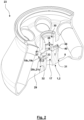
- An eccentric mass body 18a, 18b, 18c is arranged in each of the eccentric mass body receiving spaces 14a, 14b, 14c.
- the eccentric mass bodies 18 are each designed as circular ring segments 19a, 19b, 19c.
- the radially inner end face of the circular ring segments 19 is preferably designed in the shape of a cylinder segment.
- the end faces of the circular ring segments 19 in the circumferential direction are oriented radially to the axis of rotation 39.
- the lower and upper sides of the circular ring segments 19 are oriented parallel to one another with a surface normal that is oriented parallel to the axis of rotation 39.
- the outer surface 20 of the circular ring segments 19 is designed in the shape of a truncated cone segment and forms an eccentric mass body ramp surface 21 that is inclined relative to an axis of rotation 39 with a ramp surface angle 22 that is preferably 15° +/- 5°.
- Two guide projections 24, 25 each extend into the eccentric mass body receiving spaces 14, which for the embodiment shown are designed as guide bolts 26, 27 oriented parallel to the rotation axis 39.
- the guide bolts 26, 27 enter into radially oriented grooves or elongated holes on the underside of the eccentric mass body 18, the longitudinal axis of which is preferably oriented radially to the rotation axis 39.
- the engagement of the guide bolts 26, 27 in the grooves or elongated holes ensures that the eccentric mass body 18 is guided in such a way that the movement of the eccentric mass body takes place in the radial direction to the rotation axis 39.
- the counter-form-locking element 35 has an inner surface whose cross-section corresponds to the cross-section of the outer surface 16 of the form-locking element 15, so that the form-locking element 15 can be arranged in a precise and form-fitting manner for the transmission of a drive torque in the counter-form-locking element 35.
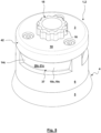
- the eccentric mass bodies 18 are in their starting position.
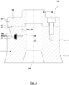
- the magnet 36 of the eccentric mass body 18 is arranged with the opposite pole adjacent to and aligned with the pole of the magnet 28, so that the starting position is secured via the magnetic force between the magnets 28, 36.
- the drive movement is transmitted to the drive head 2 via the shaft-hub connection between the drive shaft and the drive head 2, which in turn is transmitted to the rotor 23 via the positive locking between the positive locking element 15 and the counter-positive locking element 35.
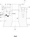
- the centrifugal force acting on the eccentric mass bodies 18 overcomes the magnetic securing force, the eccentric mass bodies 18 slide radially outwards in the eccentric mass body receiving spaces 14 until the Eccentric mass body 18 with the eccentric mass body ramp surfaces 21 come into contact with the rotor ramp surfaces 33.
- the centrifugal forces acting in the contact surface thus generated are converted, as a result of the ramp surface angle 22, into an axial force which presses the base body 29 of the rotor 23 with the rotor cone surface 31 against the drive element cone surface 5.
- the interaction of the eccentric mass bodies 18 with the eccentric mass body ramp surfaces 21 with the rotor ramp surfaces 33 of the base body 29 of the rotor forms a coupling device 37, via which a reliable connection between the rotor 23 and the drive head is ensured as long as a sufficient centrifugal force is generated on the eccentric mass bodies 18 as a result of the rotation.
- Fig. 3 , 4 and 5 show the drive head 2 in a state of the coupling device 37 in which the eccentric mass bodies 18 are in the starting position.
- Fig. 6 to 9 an operating state of the coupling device 37 in which the eccentric mass bodies 18 are in the coupled position or securing position. If, after centrifugation has ended, it is desired to remove the rotor 23 from the drive head 2, the eccentric mass bodies 18 may well still be in the securing position.
- guidance can be ensured by precisely fitting cylindrical contact surfaces between the guide surfaces 6, 32. It is also possible that in these areas there is no guidance via contact surfaces, but rather there is a play. In this case, guidance can be provided by means of guide surfaces 42, 43, which are formed by the outer surface of the circular disk 10 and an inner surface of the rotor 23.
- the form-locking element 15 and the counter-form-locking element 35 are arranged in this axial order, with the form-locking element 15 being arranged furthest in the rotor 23.
- the form-locking element 15 being arranged furthest in the rotor 23.
- the arrangement of the form-locking element 15 and the counter-form-locking element 35 and/or the eccentric mass body ramp surface 21 and the rotor ramp surface 33 can also take place in a material area of the rotor 23 that has a smaller axial distance from the drive for rigid support and a reduced lever arm of any forces.
- this design enables more material to be made available in the area of the elements mentioned, which can result in improved strength.
- the functional surfaces with which the rotor 23 interacts with the drive head 2 were formed integrally from the base body 29.
- these functional surfaces are at least partially formed by an insert sleeve 38, which can be inserted into the base body 29 and screwed to it.
- the insert sleeve 38 forms both the rotor ramp surface 33 and the counter-form-locking element 35, while the rotor cone surface 31 is formed by the base body 29.
- the eccentric mass body ramp surfaces 21 are rounded in the region of the axial edges.
- the coupling device 37 can be released in particular without tools by applying removal forces to the rotor 23. It is possible that after operation of the When the rotor 23 comes to a standstill in the centrifuge, the magnets 28, 36 automatically move the eccentric mass bodies 18 back to the unlocked starting position. However, it is also possible that, alternatively or cumulatively, the removal forces manually applied by the user to the rotor 23 are converted via the angle of inclination of the eccentric mass body ramp surfaces 21 into a force that moves the eccentric mass bodies 18 back to the unlocked starting position.
- the eccentric mass bodies 18 are made of stainless steel, whereby it is possible that the base body 29 of the rotor 23 and/or the insert sleeve 38 is made of aluminum or stainless steel.
- the counter-form-locking element 35 can also be arranged axially on the outside of the rotor 23, whereby the form-locking element 15 is then arranged in the lower end region of the base body 4.
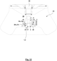
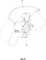
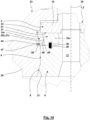
- Fig. 14 shows an embodiment in which a connection between the drive head 2 and the rotor 23 is not exclusively made and secured by the fact that the rotor 23 is clamped with the rotor cone surface 31 and the rotor ramp surface 33 between the eccentric mass body ramp surface 21 and the output element cone surface 5. Rather, an additional connection and securing is made here by the fact that the base body 29 of the rotor 23 has a groove or undercut 44.
- the eccentric mass body 18 has an outwardly oriented locking element 45.
- the locking element 45 is directly connected to the eccentric mass body ramp surface 21, wherein the locking element 45 is arranged in the end region of the eccentric mass body ramp surface 21 that has the smaller distance from the axis of rotation 39.
- the locking element 45 enters the groove or undercut 44, whereby a locked operating state is achieved.
- the locking element 45 and the groove or undercut 44 form a positive connection which blocks removal of the rotor 23 from the drive head 2 in a removal direction which corresponds to the direction of the axis of rotation 39.
- the contact surfaces 46, 47 of the eccentric mass body 18 and the groove or undercut 44 can have any shape.
- the contact surfaces 46, 47 can be designed as circular ring segment surfaces whose surface normal corresponds to the axis of rotation 39, or the contact surfaces 46, 47 can form any cone angle to the axis of rotation 39.
- Fig. 14 shows an embodiment in which the contact surface 47 of the groove or undercut 44 has a nose 48 which engages in a recess 49 of the contact surface 46.
- Unlocking can occur when, with the braking of the rotor 23, the force of the magnets 28, 36 on the eccentric mass bodies 18 becomes greater than the friction force component acting radially outward in the contact surfaces and the remaining centrifugal force acting on the eccentric mass bodies 18.
- unlocking can occur, for example, via a spring or a manually operated unlocking device.
- the eccentric mass bodies 18 each form both the eccentric mass body ramp surfaces 21 and the locking elements 45.
- first eccentric mass bodies it is also possible for first eccentric mass bodies to form the eccentric mass body ramp surfaces 21 while the locking elements 45 are formed by the second eccentric mass bodies.
Landscapes
- Centrifugal Separators (AREA)
Priority Applications (1)
| Application Number | Priority Date | Filing Date | Title |
|---|---|---|---|
| EP23183336.9A EP4487961A1 (fr) | 2023-07-04 | 2023-07-04 | Centrifugeuse, rotor pour centrifugeuse et tête d'entraînement pour centrifugeuse |
Applications Claiming Priority (1)
| Application Number | Priority Date | Filing Date | Title |
|---|---|---|---|
| EP23183336.9A EP4487961A1 (fr) | 2023-07-04 | 2023-07-04 | Centrifugeuse, rotor pour centrifugeuse et tête d'entraînement pour centrifugeuse |
Publications (1)
| Publication Number | Publication Date |
|---|---|
| EP4487961A1 true EP4487961A1 (fr) | 2025-01-08 |
Family
ID=87136481
Family Applications (1)
| Application Number | Title | Priority Date | Filing Date |
|---|---|---|---|
| EP23183336.9A Pending EP4487961A1 (fr) | 2023-07-04 | 2023-07-04 | Centrifugeuse, rotor pour centrifugeuse et tête d'entraînement pour centrifugeuse |
Country Status (1)
| Country | Link |
|---|---|
| EP (1) | EP4487961A1 (fr) |
Citations (13)
| Publication number | Priority date | Publication date | Assignee | Title |
|---|---|---|---|---|
| JPS56164040U (fr) | 1980-05-10 | 1981-12-05 | ||
| US6063018A (en) | 1997-10-23 | 2000-05-16 | Jouan | Centrifuge having force responsive locking device for securing a rotor to a drive head |
| JP2008126130A (ja) | 2006-11-20 | 2008-06-05 | Hitachi Koki Co Ltd | 遠心分離機用ロータとこれを備えた遠心分離機 |
| WO2011001729A1 (fr) | 2009-06-30 | 2011-01-06 | 株式会社久保田製作所 | Séparateur centrifuge, rotor pour séparateur centrifuge |
| WO2012059151A1 (fr) | 2010-11-01 | 2012-05-10 | Sigma Laborzentrifugen Gmbh | Montage de rotor sur palier pour une centrifugeuse de laboratoire |
| US20130203581A1 (en) | 2009-11-04 | 2013-08-08 | Awel International | Centrifuge integrating tachometric device mounted in an upper part of the chamber, especially mounted on the lid |
| US20130237399A1 (en) | 2009-11-04 | 2013-09-12 | Awel International | Centrifuge comprising visual and/or tactile indicator for indicating the accurate mounting of the rotor on the drive shaft, and corresponding rotor |
| GB2502894A (en) * | 2012-06-08 | 2013-12-11 | Thermo Electron Led Gmbh | Centrifuge drive head for releasably connecting a driving system to a rotor of a centrifuge, a set and a centrifuge comprising the drive head |
| US20140329658A1 (en) | 2013-05-02 | 2014-11-06 | Afi Centrifuge | Laboratory centrifuge comprising means for the locking in translation of a rotor on a driving motor shaft |
| US20150231648A1 (en) * | 2014-02-17 | 2015-08-20 | Thermo Electron Led Gmbh | Drive Head For Detachable Connection Of A Drive With A Rotor Of A Centrifuge, Kit Comprising Such A Drive Head, And Centrifuge |
| EP2321058B1 (fr) | 2008-09-03 | 2016-04-27 | Thermo Electron LED GmbH | Centrifugeur pourvu d'un élément d'accouplement pour le verrouillage axial d'un rotor |
| EP3012027B1 (fr) | 2014-10-21 | 2016-09-21 | Sigma Laborzentrifugen GmbH | Ensemble d'embrayage actionné par la force centrifuge pour une centrifugeuse de laboratoire |
| DE102021121259A1 (de) | 2021-08-16 | 2023-02-16 | Andreas Hettich Gmbh & Co. Kg | Zentrifuge |
-
2023
- 2023-07-04 EP EP23183336.9A patent/EP4487961A1/fr active Pending
Patent Citations (14)
| Publication number | Priority date | Publication date | Assignee | Title |
|---|---|---|---|---|
| JPS56164040U (fr) | 1980-05-10 | 1981-12-05 | ||
| US6063018A (en) | 1997-10-23 | 2000-05-16 | Jouan | Centrifuge having force responsive locking device for securing a rotor to a drive head |
| JP2008126130A (ja) | 2006-11-20 | 2008-06-05 | Hitachi Koki Co Ltd | 遠心分離機用ロータとこれを備えた遠心分離機 |
| EP2321058B1 (fr) | 2008-09-03 | 2016-04-27 | Thermo Electron LED GmbH | Centrifugeur pourvu d'un élément d'accouplement pour le verrouillage axial d'un rotor |
| WO2011001729A1 (fr) | 2009-06-30 | 2011-01-06 | 株式会社久保田製作所 | Séparateur centrifuge, rotor pour séparateur centrifuge |
| US20130237399A1 (en) | 2009-11-04 | 2013-09-12 | Awel International | Centrifuge comprising visual and/or tactile indicator for indicating the accurate mounting of the rotor on the drive shaft, and corresponding rotor |
| US20130203581A1 (en) | 2009-11-04 | 2013-08-08 | Awel International | Centrifuge integrating tachometric device mounted in an upper part of the chamber, especially mounted on the lid |
| WO2012059151A1 (fr) | 2010-11-01 | 2012-05-10 | Sigma Laborzentrifugen Gmbh | Montage de rotor sur palier pour une centrifugeuse de laboratoire |
| GB2502894A (en) * | 2012-06-08 | 2013-12-11 | Thermo Electron Led Gmbh | Centrifuge drive head for releasably connecting a driving system to a rotor of a centrifuge, a set and a centrifuge comprising the drive head |
| DE102012011531A1 (de) | 2012-06-08 | 2013-12-12 | Thermo Electron Led Gmbh | Antriebskopf zur lösbaren Verbindung eines Antriebes mit einem Rotor einer Zentrifuge für einen weiten Drehzahlbereich |
| US20140329658A1 (en) | 2013-05-02 | 2014-11-06 | Afi Centrifuge | Laboratory centrifuge comprising means for the locking in translation of a rotor on a driving motor shaft |
| US20150231648A1 (en) * | 2014-02-17 | 2015-08-20 | Thermo Electron Led Gmbh | Drive Head For Detachable Connection Of A Drive With A Rotor Of A Centrifuge, Kit Comprising Such A Drive Head, And Centrifuge |
| EP3012027B1 (fr) | 2014-10-21 | 2016-09-21 | Sigma Laborzentrifugen GmbH | Ensemble d'embrayage actionné par la force centrifuge pour une centrifugeuse de laboratoire |
| DE102021121259A1 (de) | 2021-08-16 | 2023-02-16 | Andreas Hettich Gmbh & Co. Kg | Zentrifuge |
Similar Documents
| Publication | Publication Date | Title |
|---|---|---|
| EP3012027B1 (fr) | Ensemble d'embrayage actionné par la force centrifuge pour une centrifugeuse de laboratoire | |
| DE102012011531B4 (de) | Set aus Antriebskopf und Nabe zur lösbaren Verbindung eines Antriebes mit einem Rotor einer Zentrifuge für einen weiten Drehzahlbereich | |
| EP0500489A2 (fr) | Outil et porte-outil pour machine à main | |
| DE3904259C2 (fr) | ||
| WO2015036353A2 (fr) | Dispositif de fixation | |
| EP2929992B1 (fr) | Logement de couteau pour une machine à découper | |
| EP0833024A2 (fr) | Serrure cylindrique | |
| EP2811911B1 (fr) | Dispositif de fixation pour systèmes de maintien chirurgicaux | |
| EP3669992B1 (fr) | Construction de connexion | |
| EP3856401B1 (fr) | Appareil d'agitation et/ou mélangeur | |
| DE3345293C2 (fr) | ||
| WO2020127104A1 (fr) | Système de raccordement | |
| DE69910220T2 (de) | Verriegelung für zentrifugenrotor | |
| DE19500046C1 (de) | Mechanische Kupplung | |
| EP4387769B1 (fr) | Centrifugeuse | |
| EP2121238B1 (fr) | Broche à grande vitesse de rotation | |
| EP2413756B1 (fr) | Dispositif d'entraînement pour entraîner une unité de travail | |
| EP1090705A2 (fr) | Mandrin pour outil, notamment pour scie ou machines à fraiser | |
| EP0448736B1 (fr) | Centrifugeuse à filtre réversible | |
| EP2503946B1 (fr) | Logement d'outil | |
| EP4306220B1 (fr) | Rotor de centrifugeuse et centrifugeuse | |
| EP1391627A2 (fr) | Ensemble d'embrayage | |
| EP2722128B1 (fr) | Machine-outil manuelle entraînée et dispositif de blocage de la broche correspondant | |
| EP4509215A1 (fr) | Couvercle de récipient de centrifugeuse de laboratoire et ensemble récipient de centrifugeuse de laboratoire | |
| EP1518623B1 (fr) | Dispositif de connection d'une pièce porte-outil avec une broche |
Legal Events
| Date | Code | Title | Description |
|---|---|---|---|
| PUAI | Public reference made under article 153(3) epc to a published international application that has entered the european phase |
Free format text: ORIGINAL CODE: 0009012 |
|
| STAA | Information on the status of an ep patent application or granted ep patent |
Free format text: STATUS: REQUEST FOR EXAMINATION WAS MADE |
|
| 17P | Request for examination filed |
Effective date: 20240124 |
|
| AK | Designated contracting states |
Kind code of ref document: A1 Designated state(s): AL AT BE BG CH CY CZ DE DK EE ES FI FR GB GR HR HU IE IS IT LI LT LU LV MC ME MK MT NL NO PL PT RO RS SE SI SK SM TR |
|
| GRAP | Despatch of communication of intention to grant a patent |
Free format text: ORIGINAL CODE: EPIDOSNIGR1 |
|
| STAA | Information on the status of an ep patent application or granted ep patent |
Free format text: STATUS: GRANT OF PATENT IS INTENDED |