EP4389239A1 - Tête d'extincteur pour système de détection d'incendie et procédé associé - Google Patents
Tête d'extincteur pour système de détection d'incendie et procédé associé Download PDFInfo
- Publication number
- EP4389239A1 EP4389239A1 EP23218300.4A EP23218300A EP4389239A1 EP 4389239 A1 EP4389239 A1 EP 4389239A1 EP 23218300 A EP23218300 A EP 23218300A EP 4389239 A1 EP4389239 A1 EP 4389239A1
- Authority
- EP
- European Patent Office
- Prior art keywords
- sprinkler
- control circuitry
- frangible
- bulb
- microchip
- Prior art date
- Legal status (The legal status is an assumption and is not a legal conclusion. Google has not performed a legal analysis and makes no representation as to the accuracy of the status listed.)
- Pending
Links
- 238000001514 detection method Methods 0.000 title claims description 56
- 238000000034 method Methods 0.000 title claims description 15
- 230000001960 triggered effect Effects 0.000 claims description 16
- 239000000779 smoke Substances 0.000 claims description 11
- 230000000007 visual effect Effects 0.000 claims description 11
- 230000004044 response Effects 0.000 claims description 8
- 230000000737 periodic effect Effects 0.000 claims description 6
- 238000004891 communication Methods 0.000 description 11
- 230000008901 benefit Effects 0.000 description 8
- 238000010586 diagram Methods 0.000 description 7
- 239000007788 liquid Substances 0.000 description 7
- 238000003860 storage Methods 0.000 description 7
- 238000013461 design Methods 0.000 description 5
- XLYOFNOQVPJJNP-UHFFFAOYSA-N water Substances O XLYOFNOQVPJJNP-UHFFFAOYSA-N 0.000 description 5
- 230000004913 activation Effects 0.000 description 4
- 239000012530 fluid Substances 0.000 description 3
- 230000006870 function Effects 0.000 description 3
- 238000004519 manufacturing process Methods 0.000 description 3
- 238000012545 processing Methods 0.000 description 3
- PXHVJJICTQNCMI-UHFFFAOYSA-N Nickel Chemical compound [Ni] PXHVJJICTQNCMI-UHFFFAOYSA-N 0.000 description 2
- 238000013500 data storage Methods 0.000 description 2
- 230000001419 dependent effect Effects 0.000 description 2
- 230000004048 modification Effects 0.000 description 2
- 238000012986 modification Methods 0.000 description 2
- 230000001629 suppression Effects 0.000 description 2
- WHXSMMKQMYFTQS-UHFFFAOYSA-N Lithium Chemical compound [Li] WHXSMMKQMYFTQS-UHFFFAOYSA-N 0.000 description 1
- HBBGRARXTFLTSG-UHFFFAOYSA-N Lithium ion Chemical compound [Li+] HBBGRARXTFLTSG-UHFFFAOYSA-N 0.000 description 1
- 230000001133 acceleration Effects 0.000 description 1
- 238000004378 air conditioning Methods 0.000 description 1
- OJIJEKBXJYRIBZ-UHFFFAOYSA-N cadmium nickel Chemical compound [Ni].[Cd] OJIJEKBXJYRIBZ-UHFFFAOYSA-N 0.000 description 1
- 230000001413 cellular effect Effects 0.000 description 1
- 238000010276 construction Methods 0.000 description 1
- 238000007405 data analysis Methods 0.000 description 1
- 238000009826 distribution Methods 0.000 description 1
- 238000005516 engineering process Methods 0.000 description 1
- 239000011521 glass Substances 0.000 description 1
- 238000010438 heat treatment Methods 0.000 description 1
- 238000009434 installation Methods 0.000 description 1
- 229910052744 lithium Inorganic materials 0.000 description 1
- 229910001416 lithium ion Inorganic materials 0.000 description 1
- 238000007726 management method Methods 0.000 description 1
- 229910052759 nickel Inorganic materials 0.000 description 1
- 230000003287 optical effect Effects 0.000 description 1
- 230000008569 process Effects 0.000 description 1
- 239000007787 solid Substances 0.000 description 1
- 238000012546 transfer Methods 0.000 description 1
Images



Classifications
-
- A—HUMAN NECESSITIES
- A62—LIFE-SAVING; FIRE-FIGHTING
- A62C—FIRE-FIGHTING
- A62C37/00—Control of fire-fighting equipment
- A62C37/08—Control of fire-fighting equipment comprising an outlet device containing a sensor, or itself being the sensor, i.e. self-contained sprinklers
- A62C37/10—Releasing means, e.g. electrically released
- A62C37/11—Releasing means, e.g. electrically released heat-sensitive
- A62C37/14—Releasing means, e.g. electrically released heat-sensitive with frangible vessels
-
- A—HUMAN NECESSITIES
- A62—LIFE-SAVING; FIRE-FIGHTING
- A62C—FIRE-FIGHTING
- A62C37/00—Control of fire-fighting equipment
- A62C37/08—Control of fire-fighting equipment comprising an outlet device containing a sensor, or itself being the sensor, i.e. self-contained sprinklers
- A62C37/10—Releasing means, e.g. electrically released
- A62C37/11—Releasing means, e.g. electrically released heat-sensitive
- A62C37/12—Releasing means, e.g. electrically released heat-sensitive with fusible links
-
- A—HUMAN NECESSITIES
- A62—LIFE-SAVING; FIRE-FIGHTING
- A62C—FIRE-FIGHTING
- A62C31/00—Delivery of fire-extinguishing material
- A62C31/02—Nozzles specially adapted for fire-extinguishing
-
- A—HUMAN NECESSITIES
- A62—LIFE-SAVING; FIRE-FIGHTING
- A62C—FIRE-FIGHTING
- A62C37/00—Control of fire-fighting equipment
- A62C37/04—Control of fire-fighting equipment with electrically-controlled release
-
- A—HUMAN NECESSITIES
- A62—LIFE-SAVING; FIRE-FIGHTING
- A62C—FIRE-FIGHTING
- A62C37/00—Control of fire-fighting equipment
- A62C37/36—Control of fire-fighting equipment an actuating signal being generated by a sensor separate from an outlet device
- A62C37/38—Control of fire-fighting equipment an actuating signal being generated by a sensor separate from an outlet device by both sensor and actuator, e.g. valve, being in the danger zone
- A62C37/40—Control of fire-fighting equipment an actuating signal being generated by a sensor separate from an outlet device by both sensor and actuator, e.g. valve, being in the danger zone with electric connection between sensor and actuator
-
- A—HUMAN NECESSITIES
- A62—LIFE-SAVING; FIRE-FIGHTING
- A62C—FIRE-FIGHTING
- A62C37/00—Control of fire-fighting equipment
- A62C37/50—Testing or indicating devices for determining the state of readiness of the equipment
Definitions
- the invention generally relates to sprinkler heads for fire detection systems. More particularly, the invention relates to a sprinkler head adapted to operate in a tracking mode and a releasing mode in a fire detection system.
- Fire detection systems include sprinkler devices arranged to expel or disperse fluid for suppressing or preventing fire.
- Fire detection systems are typically connected to a water supply system providing sufficient pressure and flowrate to water within a network of pipes.
- Sprinkler devices are mounted onto the pipes at different locations within a room.
- Sprinkler devices are preferably spaced apart and ensure all areas within the building are covered.
- Each of the sprinkler devices typically includes sprinkler bulbs that are frangible and rupture at predetermined temperatures. The increase in ambient temperature raises the temperature of a liquid within the frangible bulb causing the liquid to expand. When the pressure within the frangible bulb expands beyond a threshold pressure due to expansion of the liquid, the frangible bulb ruptures thereby causing the sprinkler device to emit fire suppression fluid. Therefore, sprinkler bulbs operate as a type of mechanical fuse, which releases fire suppression fluid from an associated source when they break.
- Existing fire detection systems employ sprinkler bulbs that wirelessly transmit information from such bulbs. The information received from the bulbs helps fire detection systems to identify which sprinkler bulbs are ruptured and accordingly identify a fire location.
- Existing fire sprinkler bulbs with integrated remote activation functionality have no embedded digital tracking capabilities and therefore, limiting their use. Since sprinkler bulbs are typically small, frangible, single-use components of the fire detection system, complexity, and cost of the components used for tracking and activation of the sprinkler bulbs reduce their applicability. Improvements to fire detection systems employing sprinkler bulbs having improved tracking and activation features without increasing complexity or cost of implementation are therefore desirable.
- a sprinkler head including a sprinkler body and a frangible sprinkler bulb connected to the sprinkler body.
- the frangible sprinkler bulb includes a resistive track embedded in a cylindrical wall.
- At least one microchip and at least one diode are operationally connected in series to the resistive track. Further, the at least one microchip and the at least one diode are connected in parallel to each other.
- a tracking mode a first current flows from a first terminal to a second terminal sequentially through the resistive track and the at least one microchip.
- a second current flows from the second terminal to the first terminal sequentially through the at least one diode and the resistive track.
- the sprinkler head further includes a mounting adaptor for connecting with a supply conduit.
- the sprinkler head further includes a seal for fluidly isolating the frangible sprinkler bulb from the supply conduit.
- the resistive track is embedded in the cylindrical wall in a pattern including at least one of a serpentine pattern, a periodic waveform pattern, a waveform pattern, and a helical pattern.
- the second current passing through the embedded resistive track disintegrates the frangible sprinkler bulb.
- a fire detection system comprises the sprinkler head and a control circuitry.
- the control circuitry is configured to communicate, during the tracking mode, with the at least one microchip in the frangible sprinkler bulb to obtain information related to the frangible sprinkler bulb.
- the information includes at least one of a location of the frangible sprinkler bulb, a temperature of a region surrounding the frangible sprinkler bulb, smoke particulate density of the region surrounding the frangible sprinkler bulb, and a resistance of the resistive track.
- control circuitry is configured to communicate, during the releasing mode, with the at least one microchip in the frangible sprinkler bulb to trigger the second current based on the determined resistance of the resistive track.
- the releasing mode is triggered based on the control circuitry receiving an input.
- the releasing mode is triggered based on the control circuitry identifying the obtained information exceeding at least one predefined criteria.
- control circuitry is further configured to detect a fire event based on the control circuitry receiving absence of response from the at least one microchip during the tracking mode.
- the tracking mode is triggered periodically at predefined intervals.
- the tracking mode is triggered based on the control circuitry receiving an input.
- control circuitry is further configured to generate a notification on a computing device based on at least one of triggering of the releasing mode and detection of the fire event.
- the notification is one of an audio notification, a visual notification, and audio-visual notification, and a haptic notification.
- a fire detection method includes the step of providing a fire detection system including a sprinkler head and control circuitry.
- the sprinkler head includes a sprinkler body and a frangible sprinkler bulb connected to the sprinkler body.
- the frangible sprinkler bulb includes a resistive track embedded in a cylindrical wall. At least one microchip and at least one diode are operationally connected in series to the resistive track. Further, the at least one microchip and the at least one diode are connected in parallel to each other.
- the control circuitry communicates with the at least one microchip of the frangible sprinkler bulb. Next, the control circuitry, during a tracking mode, obtains information related to the frangible sprinkler bulb.
- the information includes at least one of a location of the frangible sprinkler bulb, a temperature of a region surrounding the frangible sprinkler bulb, smoke particulate density of the region surrounding the frangible sprinkler bulb, and a resistance of the resistive track.
- the control circuitry detects, during the tracking mode, a fire event based on the control circuitry receiving absence of response from the at least one microchip during the tracking mode.
- the method includes the step of providing a fire detection system including a sprinkler head and control circuitry.
- the sprinkler head includes a sprinkler body and a frangible sprinkler bulb connected to the sprinkler body.
- the frangible sprinkler bulb includes a resistive track embedded in a cylindrical wall. At least one microchip and at least one diode are operationally connected in series to the resistive track. Further, the at least one microchip and the at least one diode are connected in parallel to each other.
- the fire detection method includes the control circuitry of the fire detection system communicating with the at least one microchip of the frangible sprinkler bulb. Next, the control circuitry, during a tracking mode, obtains information related to the frangible sprinkler bulb.
- the information includes at least one of a location of the frangible sprinkler bulb, a temperature of a region surrounding the frangible sprinkler bulb, smoke particulate density of the region surrounding the frangible sprinkler bulb, and a resistance of the resistive track.
- the control circuitry detects, during the tracking mode, a fire event based on the control circuitry identifying the obtained information exceeding at least one predefined criteria.
- control circuitry is further configured to trigger a releasing mode based on the control circuitry identifying the obtained information exceeding the at least one predefined criteria.
- the releasing mode is triggered based on the control circuitry receiving an input.
- the control circuitry is further configured to generate a notification on a computing device based on triggering of the releasing mode or detection of the fire event.
- the notification includes an audio notification, a visual notification, an audio-visual notification, and a haptic notification.
- any terms used herein such as but not limited to “includes,” “comprises,” “has,” “have” and grammatical variants thereof do not specify an exact limitation or restriction and certainly do not exclude the possible addition of one or more features or elements, unless otherwise stated, and must not be taken to exclude the possible removal of one or more of the listed features and elements, unless otherwise stated with the limiting language “must comprise” or “needs to include.”
- unit used herein may imply a unit including, for example, one of hardware, software, and firmware or a combination of two or more of them.
- the “unit” may be interchangeably used with a term such as logic, a logical block, a component, a circuit, and the like.
- the “unit” may be a minimum system component for performing one or more functions or may be a part thereof.
- FIG. 1A exemplarily illustrates a sprinkler head 100 comprising a sprinkler body 101 and a frangible sprinkler bulb 102 connected to the sprinkler body 101.
- the "frangible sprinkler bulb 102" refers to a heat sensitive glass bulb configured to store a liquid. The liquid within the frangible sprinkler bulb 102 expands with increase in temperature of a region 202 (shown in FIG. 2 ) surrounding the frangible sprinkler bulb 102. When the activation temperature or the temperature at which the frangible sprinkler bulb 102 is designed to rupture is reached, the frangible sprinkler bulb 102 disintegrates.
- the liquid stored within the frangible sprinkler bulb 102 is colour coded to indicate a temperature rating or the design temperature at which the frangible sprinkler bulb 102 will rupture.
- the frangible sprinkler bulb 102 breaks because of the thermal expansion of the liquid inside the frangible sprinkler bulb 102. The time taken until the frangible sprinkler bulb 102 breaks is dependent on the temperature of the surrounding region 202. Below the design temperature, the frangible sprinkler bulb 102 does not break, and above the design temperature, the frangible sprinkler bulb 102 breaks, taking less time to break as temperature increases above the design threshold.
- the sprinkler head 100 further includes a mounting adaptor 109 for connecting with a supply conduit 110.
- the sprinkler head 100 includes a seal 111 for fluidly isolating the frangible sprinkler bulb 102 from the supply conduit 110.
- the seal 111 ruptures causing water within the supply conduit 110 to be released at high pressure.
- the frangible sprinkler bulb 102 disclosed herein, functions both as a tracking device and a fire extinguishing device as will be discussed in detail.
- FIG. 1B exemplarily illustrates an enlarged view of the frangible sprinkler bulb 102 of the sprinkler head 100 shown in FIG. 1A .
- the frangible sprinkler bulb 102 includes a cylindrical wall 103 and a resistive track 104 embedded in the cylindrical wall 103.
- the resistive track 104 is embedded in the cylindrical wall 103 in a pattern including, for example, but not limited to a serpentine pattern, a periodic waveform pattern, a waveform pattern, and a helical pattern.
- the resistive track 104 may be etched onto an external surface of the cylindrical wall 103. In other embodiments, the resistive track 104 may be etched along the entire length of the cylindrical wall 103.
- At least one microchip 105 and at least one diode 106 are operationally connected in series to the resistive track 104. Moreover, the at least one microchip 105 and the at least one diode 106 are connected in parallel to each other as exemplarily illustrated in FIGS. 1C-1D .
- a battery or power source may be electrically coupled to first and second terminals (107, 108) of the resistive track 104 to supply electrical power under control of the microchip 105 to heat the frangible sprinkler bulb 102.
- the power source may be, for example, a battery, such as a rechargeable battery or a non-rechargeable battery. Examples of suitable batteries include, for example, a lithium battery (such as a lithium-ion battery), a nickel battery (such as a nickel-cadmium battery), and an alkaline battery.
- FIG. 1C exemplarily illustrates a circuit diagram 150 showing the frangible sprinkler bulb 102 operating in a tracking mode.
- FIG. 1D exemplarily illustrates a circuit diagram 150 showing the frangible sprinkler bulb 102 operating in a releasing mode.
- the tracking mode refers to a mode of operation of the frangible sprinkler bulb 102 in which information is gathered from the frangible sprinkler bulb 102 using the microchip 105. The information may be gathered periodically or at predefined intervals set by an operator. Alternatively, the information may be gathered on demand at random intervals.
- the releasing mode refers to a mode of operation of the frangible sprinkler bulb 102 in which the flow of current is reversed in comparison to the flow of current in the tracking mode. Moreover, the current is of a larger magnitude than the current flow in the tracking mode causing the resistive track 104 to heat the cylindrical wall 103 as exemplarily illustrated in FIG. 1B .
- a first current flows from the first terminal 107 to the second terminal 108 sequentially through the resistive track 104 and the at least one microchip 105.
- a second current flows from the second terminal 108 to the first terminal 107 sequentially through the at least one diode 106 and the resistive track 104.
- the second current passing through the embedded resistive track 104 disintegrates the frangible sprinkler bulb 102.
- FIG. 2 exemplarily illustrates a schematic block diagram showing an implementation of a fire detection system 200.
- the fire detection system 200 includes the sprinkler head 100 as disclosed in the detailed description of FIG. 1A and control circuitry 201.
- the sprinkler head 100 is arranged to dispense water in the region 202 when a fire event is detected within the region 202.
- control circuitry 201 and "microchip 105" may be construed to encompass one or a combination of microprocessors, suitable logic, circuits, audio interfaces, visual interfaces, haptic interfaces, or the like.
- the control circuitry 201 and the microchip 105 may include, but are not limited to a microcontroller, a Reduced Instruction Set Computing (RISC) processor, an Application-Specific Integrated Circuit (ASIC) processor, a Complex Instruction Set Computing (CISC) processor, a central processing unit (CPU), a graphics processing unit (GPU), a state machine, and/or other processing units 201-1 or circuits.
- RISC Reduced Instruction Set Computing
- ASIC Application-Specific Integrated Circuit
- CISC Complex Instruction Set Computing
- CPU central processing unit
- GPU graphics processing unit
- state machine and/or other processing units 201-1 or circuits.
- the control circuitry 201 may also comprise suitable logic, circuits, interfaces, and/or code that may be configured to execute a set of instructions stored in a memory unit 201-2.
- the memory unit 201-2 may include, but are not limited to, Electrically Erasable Programmable Read-only Memory (EEPROM), Random Access Memory (RAM), Read Only Memory (ROM), Hard Disk Drive (HDD), Flash memory, Solid-State Drive (SSD), and/or CPU cache memory.
- EEPROM Electrically Erasable Programmable Read-only Memory
- RAM Random Access Memory
- ROM Read Only Memory
- HDD Hard Disk Drive
- Flash memory Solid-State Drive
- SSD Solid-State Drive
- the control circuitry 201 further includes a communications unit 201-3 configured to communicate with the microchip 105 and other components of the fire detection system 200 such as sensors within the region 202 and a computing device 203. During the tracking mode, the control circuitry 201 communicates with the microchip 105 in the frangible sprinkler bulb 102 to obtain information related to the frangible sprinkler bulb 102.
- the information related to the frangible sprinkler bulb 102 includes a location of the frangible sprinkler bulb 102, a temperature of the region 202 surrounding the frangible sprinkler bulb 102, smoke particulate density of the region 202 surrounding the frangible sprinkler bulb 102, a resistance of the resistive track 104, etc.
- the information related to the frangible sprinkler bulb 102 includes internal pressure of the frangible sprinkler bulb 102, a temperature of the frangible sprinkler bulb 102, etc.
- the resistive track 104 is embedded in the cylindrical wall 103 in a pattern including at least one of a serpentine pattern, a periodic waveform pattern, a waveform pattern, and a helical pattern. Since the resistive track 104 is configured in different patterns on different frangible sprinkler bulbs 102, the resistance is different for different frangible sprinkler bulbs 102. This differentiating feature makes each frangible sprinkler bulb 102 of the fire detection system 100 unique and as though having a unique identifying feature.
- the microchip 105 obtains this information and transmits the information to the control circuitry 201.
- the tracking mode is triggered periodically at predefined intervals.
- predefined intervals is used to mean a periodic interval such as every second, every 5 seconds, every minute, every hour, and the like. The predefined interval may be stored in the memory unit 201-2 or may be adjusted by an operator using the control circuitry 201.
- the tracking mode is triggered based on the control circuitry 201 receiving an input from operators or authorized personnel.
- the control circuitry 201 is further configured to detect a fire event based on the control circuitry 201 receiving no response or absence of response from the at least one microchip 105 during the tracking mode.
- the control circuitry 201 is integrated as a part of the fire detection system 200 remote from the sprinkler head 100.
- the fire detection system 200 may also comprise a plurality of sensors configured to detect one or more parameters of the region 202.
- the sensors may include one or a combination of temperature sensors, air quality sensors, and the like.
- the sensors may be installed as a part of a building management system or other Heating, Ventilating and Air Conditioning system. Using these sensors, the control circuitry 201 and/or the microchip 105 detects information regarding different parameters of the region 202.
- control circuitry 201 or the microchip 105 determines feedback from the sensors exceeds at least one predefined criteria, transmits a trigger signal to the microchip 105 to actuate the releasing mode.
- predefined criteria includes threshold values of the temperature of the region 202 surrounding the frangible sprinkler bulb 102, smoke particulate density of the region 202 surrounding the frangible sprinkler bulb 102, internal pressure of the frangible sprinkler bulb 102, etc.
- the control circuitry communicates with the at least one microchip 105 in the frangible sprinkler bulb 102 to trigger the second current based on the determined resistance of the resistive track 104. Since the resistance is different for different frangible sprinkler bulbs 102, the current flow should be sufficient to raise the temperature to a magnitude sufficient to rupture the cylindrical wall 103 exemplarily illustrated in FIG. 1B .
- the releasing mode is triggered based on the control circuitry 201 receiving an input from an operator or a user of the fire detection system 200.
- the communications unit 201-3 also transmits data to and receives data from the computing device 203 via a communications network 204.
- the communications unit 201-3 may be configured of, for example, a telematic transceiver (DCM), a mayday battery, a GPS, a data communication module ASSY, a telephone microphone ASSY, and a telephone antenna ASSY.
- the communications network 204 may include, but is not limited to, a Wide Area Network (WAN), a cellular network, such as a 3G, 4G, or 5G network, an Internet-based mobile ad hoc networks (IMANET), etc.
- WAN Wide Area Network
- IMANET Internet-based mobile ad hoc networks
- the communications network 204 may also include wired media such as a wired network or direct-wired connection, and wireless media such as acoustic, radio frequency (RF), microwave, infrared (IR) and other wireless media.
- the computing device 203 may be implemented as a portion of a small-form factor portable (or mobile) electronic device such as a cell phone, a personal data assistant (PDA), a personal media player device, a wireless web-watch device, a personal headset device, an application specific device, or a hybrid device that include any of the above functions.
- the computing device 203 may also be implemented as a personal computer including both laptop computer and non-laptop computer configurations.
- the computing device 203 can also be any type of network computing device.
- the computing device 203 can also be an automated system as described herein.
- the computing device 203 may have additional features or functionality, and additional interfaces to facilitate communications between basic configuration and any devices and interfaces.
- a bus/interface controller may be used to facilitate communications between a basic configuration and one or more data storage devices via a storage interface bus.
- Data storage devices may be removable storage devices, non-removable storage devices, or a combination thereof.
- removable storage and non-removable storage devices include magnetic disk devices such as flexible disk drives and hard-disk drives (HDD), optical disk drives such as compact disk (CD) drives or digital versatile disk (DVD) drives, solid state drives (SSD), and tape drives to name a few.
- Example computer storage media may include volatile and non-volatile, removable and non-removable media implemented in any method or technology for storage of information, such as computer readable instructions, data structures, program modules, or other data systems can also be used for data analysis and to determine when (e.g., acceleration and/or speed).
- the communications unit 201-3 of the control circuitry 201 When a fire event is detected or the releasing mode is triggered in at least one of the frangible sprinkler bulbs 102, the communications unit 201-3 of the control circuitry 201 generates a trigger signal which is conveyed to an interface or communications unit of the computing device 203.
- the computing device 203 receives the trigger signal, the computing device 203 generates a notification such as an audio notification, a visual notification, and audio-visual notification, and a haptic notification.
- the audio notification may include a loud warning siren or alarm which may be generated for a continuous or periodic interval of time.
- the audio notification is configured to be cleared or switched off based on an input received via the computing device 203, after which time the computing device 203 resumes to a normal indication without the emergency audio notification.
- the input may include an input received via a haptic interface of the computing device 203, an ON/OFF switch, biometric/RFID authentication by authorized security or safety personnel, etc.
- This means the audio notification provides the alert continuously to the operator of the computing device 203 until the operator shuts off the notification.
- the computing device 203 generates a visual notification in addition to the audio notification via a display interface of the computing device 203.
- the display may comprise suitable logic, circuitry, interfaces, and/or code that may be configured to render various types of information and/or entertainment content via a user interface.
- the display may be a flashing visual indicator, such as a Light Emitting Diode (LED), indicator lights, or the like.
- the user interface may be a customized Graphic User Interface (GUI) configured to display information related to the fire detection system 200 such as the predefined criteria set by the operator, location of the fire, number of damaged frangible sprinkler bulbs 102, etc.
- GUI Graphic User Interface
- the display may include but is not limited to a projection-based display, an electro-chromic display, a flexible display, and/or holographic display.
- the display may be a touchscreen display, a tactile electronic display, and/or a touchable hologram.
- the display may be configured to receive inputs from the operator for setting or modifying the predefined criteria, the predefined intervals, etc.
- the authorized personnel/operator may be prompted to clear the audio or visual notification.
- the audio notification, the visual notification, or the audio-visual notification is configured to stop only based on an input received from the operator via the computing device 203. Consequently, the computing device 203 configures the audio interface and/or the display interface to return to a normal indication mode.
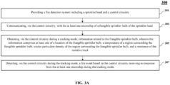
- FIG. 3A exemplarily illustrates a flowchart indicating a fire detection method 300 using the fire detection system 200 shown in FIG. 2 .
- the fire detection system 200 is provided as disclosed in the detailed description of FIG. 2 .
- the fire detection system 200 includes the sprinkler head 100 and the control circuitry 201.
- the sprinkler head 100 includes the sprinkler body 101 and the frangible sprinkler bulb 102 connected to the sprinkler body 101 as disclosed in the detailed description of FIGS. 1A-1B .
- the frangible sprinkler bulb 102 includes the resistive track 104 embedded in the cylindrical wall 103.
- the at least one microchip 105 and the at least one diode 106 are operationally connected in series to the resistive track 104. Further, the at least one microchip 105 and the at least one diode 106 are connected in parallel to each other.
- the fire detection system 200 may comprise a plurality of sprinkler heads 100, such that each sprinkler head 100 is as described in the detailed descriptions of FIGS. 1A-1D .
- the control circuitry 201 of the fire detection system 200 communicates with the at least one microchip 105 of the frangible sprinkler bulb 102.
- the control circuitry 201 of the fire detection system 200 obtains information related to the frangible sprinkler bulb 102.
- the information includes at least one of a location of the frangible sprinkler bulb 102, a temperature of the region 202 surrounding the frangible sprinkler bulb 102, smoke particulate density of the region 202 surrounding the frangible sprinkler bulb 102, and a resistance of the resistive track 104.
- control circuitry 201 detects a fire event based on the control circuitry 201 receiving no response or absence of response from the at least one microchip 105.
- FIG. 3B exemplarily illustrates a flowchart indicating a fire detection method 400 using the fire detection system shown in FIG. 2 .
- the fire detection system 200 is provided as disclosed in the detailed description of FIG. 2 .
- the fire detection system 200 includes the sprinkler head 100 and the control circuitry 201.
- the sprinkler head 100 includes the sprinkler body 101 and the frangible sprinkler bulb 102 connected to the sprinkler body 101 as disclosed in the detailed description of FIGS. 1A-1B .
- the frangible sprinkler bulb 102 includes the resistive track 104 embedded in the cylindrical wall 103.
- the at least one microchip 105 and the at least one diode 106 are operationally connected in series to the resistive track 104. Further, the at least one microchip 105 and the at least one diode 106 are connected in parallel to each other.
- the fire detection system 200 may comprise a plurality of sprinkler heads 100, wherein each sprinkler head 100 is as described in the detailed descriptions of FIGS. 1A-1D .
- the control circuitry 201 of the fire detection system 200 communicates with the at least one microchip 105 of the frangible sprinkler bulb 102.
- the control circuitry 201 of the fire detection system 200 obtains information related to the frangible sprinkler bulb 102.
- the information includes at least one of a location of the frangible sprinkler bulb 102, a temperature of the region 202 surrounding the frangible sprinkler bulb 102, smoke particulate density of the region 202 surrounding the frangible sprinkler bulb 102, and a resistance of the resistive track 104.
- the control circuitry 201 detects the fire event based on the control circuitry 201 identifying the obtained information exceeding at least one predefined criteria.
- the control circuitry 201 is further configured to trigger a releasing mode based on the control circuitry 201 identifying the obtained information exceeding the at least one predefined criteria.
- the releasing mode may also be triggered based on the control circuitry 201 receiving an input.
- the control circuitry 201 is further configured to generate a notification on the computing device 203 when the releasing mode is triggered or the fire event is detected as disclosed in the detailed description of FIG. 2 .
- the notification is, for example, an audio notification, a visual notification, an audio-visual notification, a haptic notification, and the like.
- the sprinkler head 100 has a reduced production time since the resistive track 104 and the microchip 105 are embedded on the external surface of existing frangible sprinkler bulbs 102. This means no complex additional components/wiring or modification in the existing frangible sprinkler bulbs 102 are made to implement the improved fire detection system 200. As such, the cost and complexity of the improved sprinkler head 100 are reduced. Furthermore, since the resistive track 104 is embedded directly on the external surface of the frangible sprinkler bulb 102, the heat transfer is improved thereby increasing reliability of disintegration of the frangible sprinkler bulbs 102 in the event of a fire.
- the tracking mode and releasing modes of the frangible sprinkler bulbs 102 are isolated from the functioning of a water distribution system, the reliability of the fire detection system 200 is further increased.
- the tracking modes can be activated from a factory or manufacturing facility to improve tracking of the frangible sprinkler bulbs 102 during transit from production till installation.
Landscapes
- Health & Medical Sciences (AREA)
- Public Health (AREA)
- Business, Economics & Management (AREA)
- Emergency Management (AREA)
- Fire-Extinguishing By Fire Departments, And Fire-Extinguishing Equipment And Control Thereof (AREA)
Applications Claiming Priority (1)
| Application Number | Priority Date | Filing Date | Title |
|---|---|---|---|
| US202263476173P | 2022-12-20 | 2022-12-20 |
Publications (1)
| Publication Number | Publication Date |
|---|---|
| EP4389239A1 true EP4389239A1 (fr) | 2024-06-26 |
Family
ID=89224272
Family Applications (1)
| Application Number | Title | Priority Date | Filing Date |
|---|---|---|---|
| EP23218300.4A Pending EP4389239A1 (fr) | 2022-12-20 | 2023-12-19 | Tête d'extincteur pour système de détection d'incendie et procédé associé |
Country Status (2)
| Country | Link |
|---|---|
| US (1) | US20240198155A1 (fr) |
| EP (1) | EP4389239A1 (fr) |
Cited By (1)
| Publication number | Priority date | Publication date | Assignee | Title |
|---|---|---|---|---|
| EP4541431A1 (fr) * | 2023-10-17 | 2025-04-23 | Carrier Corporation | Système et procédé de vérification de l'intégrité fonctionnelle d'une tête d'extincteur |
Citations (4)
| Publication number | Priority date | Publication date | Assignee | Title |
|---|---|---|---|---|
| US20180361183A1 (en) * | 2015-11-18 | 2018-12-20 | Obschestvo S Ogranichennoi Otvetstvennostju Fornosovskoe Nauchnoproizvodstvennoe Predpriyatie | Sprinkler with activation monitoring |
| US20190083833A1 (en) * | 2017-09-20 | 2019-03-21 | Job Lizenz Gmbh & Co. Kg | Sprinkler head |
| WO2021220157A1 (fr) * | 2020-04-28 | 2021-11-04 | Tyco Fire Products Lp | Systèmes et procédés d'ampoules d'arrosage à l'aide d'une trace résistive |
| EP3623019B1 (fr) * | 2018-09-13 | 2022-06-15 | Marioff Corporation OY | Extincteur d'incendie comportant une fonction de libération à distance |
Family Cites Families (2)
| Publication number | Priority date | Publication date | Assignee | Title |
|---|---|---|---|---|
| US12029930B2 (en) * | 2018-08-24 | 2024-07-09 | Tyco Fire Products Lp | Fire protection device with conformal coating |
| ES2925040T3 (es) * | 2018-12-05 | 2022-10-13 | Marioff Corp Oy | Función de detección de grietas para un rociador contra incendios con bombilla frangible |
-
2023
- 2023-12-19 EP EP23218300.4A patent/EP4389239A1/fr active Pending
- 2023-12-19 US US18/545,197 patent/US20240198155A1/en active Pending
Patent Citations (4)
| Publication number | Priority date | Publication date | Assignee | Title |
|---|---|---|---|---|
| US20180361183A1 (en) * | 2015-11-18 | 2018-12-20 | Obschestvo S Ogranichennoi Otvetstvennostju Fornosovskoe Nauchnoproizvodstvennoe Predpriyatie | Sprinkler with activation monitoring |
| US20190083833A1 (en) * | 2017-09-20 | 2019-03-21 | Job Lizenz Gmbh & Co. Kg | Sprinkler head |
| EP3623019B1 (fr) * | 2018-09-13 | 2022-06-15 | Marioff Corporation OY | Extincteur d'incendie comportant une fonction de libération à distance |
| WO2021220157A1 (fr) * | 2020-04-28 | 2021-11-04 | Tyco Fire Products Lp | Systèmes et procédés d'ampoules d'arrosage à l'aide d'une trace résistive |
Cited By (1)
| Publication number | Priority date | Publication date | Assignee | Title |
|---|---|---|---|---|
| EP4541431A1 (fr) * | 2023-10-17 | 2025-04-23 | Carrier Corporation | Système et procédé de vérification de l'intégrité fonctionnelle d'une tête d'extincteur |
Also Published As
| Publication number | Publication date |
|---|---|
| US20240198155A1 (en) | 2024-06-20 |
Similar Documents
| Publication | Publication Date | Title |
|---|---|---|
| US10255773B2 (en) | Security system providing a localized humanly-perceivable alert for identifying a facility to emergency personnel | |
| US9799190B2 (en) | Security system tracking of remote items using reduced power | |
| ES2633962T3 (es) | Mazo de cables para un sistema automático de extinción de incendios | |
| ES2709900T3 (es) | Monitor de dispositivo y sistema de supervisión remota | |
| CN100538758C (zh) | 用于安全系统的mems传感器单元及其操作方法 | |
| EP4036883B1 (fr) | Système de detection d'incendie | |
| CN112566702B (zh) | 具有远程释放功能的消防喷洒器 | |
| WO2008105578A1 (fr) | Système destiné à surveiller des sinistres industriels dans l'industrie de fabrication | |
| EP4389239A1 (fr) | Tête d'extincteur pour système de détection d'incendie et procédé associé | |
| US20190369615A1 (en) | System and method for verifying the presence and vital signs of pilots in a cockpit of an airplane | |
| US8736444B2 (en) | System and method for wireless heat detection | |
| EP4541431A1 (fr) | Système et procédé de vérification de l'intégrité fonctionnelle d'une tête d'extincteur | |
| JP5278797B2 (ja) | 人存在報知装置 | |
| KR20050064510A (ko) | 원격제어 소방시스템 | |
| WO2022081021A1 (fr) | Système de détection d'alarme | |
| EP3936196A1 (fr) | Appareil d'extinction d'incendie ayant une fonction de prédiction d'incendie | |
| US20020067253A1 (en) | Method and apparatus for the display of alarm information on a portable device | |
| US10484830B1 (en) | Indoor positioning system for fireman | |
| CN111127850A (zh) | 救援辅助装置、方法、系统和机器可读介质 | |
| CN209879678U (zh) | 一种动车场防非法侵入报警系统 | |
| JP2017157092A (ja) | 警報器 | |
| JP2017167786A (ja) | 警報システム | |
| KR200163416Y1 (ko) | 전화경보장치 | |
| GB2530120A (en) | Alarm system | |
| JP2010267183A (ja) | 警報器及び警報システム |
Legal Events
| Date | Code | Title | Description |
|---|---|---|---|
| PUAI | Public reference made under article 153(3) epc to a published international application that has entered the european phase |
Free format text: ORIGINAL CODE: 0009012 |
|
| STAA | Information on the status of an ep patent application or granted ep patent |
Free format text: STATUS: THE APPLICATION HAS BEEN PUBLISHED |
|
| AK | Designated contracting states |
Kind code of ref document: A1 Designated state(s): AL AT BE BG CH CY CZ DE DK EE ES FI FR GB GR HR HU IE IS IT LI LT LU LV MC ME MK MT NL NO PL PT RO RS SE SI SK SM TR |
|
| STAA | Information on the status of an ep patent application or granted ep patent |
Free format text: STATUS: REQUEST FOR EXAMINATION WAS MADE |
|
| 17P | Request for examination filed |
Effective date: 20241220 |