EP4389577A2 - Agencement de pignon multiple et système modulaire pour agencements de pignon multiple - Google Patents
Agencement de pignon multiple et système modulaire pour agencements de pignon multiple Download PDFInfo
- Publication number
- EP4389577A2 EP4389577A2 EP23020556.9A EP23020556A EP4389577A2 EP 4389577 A2 EP4389577 A2 EP 4389577A2 EP 23020556 A EP23020556 A EP 23020556A EP 4389577 A2 EP4389577 A2 EP 4389577A2
- Authority
- EP
- European Patent Office
- Prior art keywords
- pinion
- outboard
- inboard
- cluster
- arrangement
- Prior art date
- Legal status (The legal status is an assumption and is not a legal conclusion. Google has not performed a legal analysis and makes no representation as to the accuracy of the status listed.)
- Pending
Links
Images


Classifications
-
- B—PERFORMING OPERATIONS; TRANSPORTING
- B62—LAND VEHICLES FOR TRAVELLING OTHERWISE THAN ON RAILS
- B62M—RIDER PROPULSION OF WHEELED VEHICLES OR SLEDGES; POWERED PROPULSION OF SLEDGES OR SINGLE-TRACK CYCLES; TRANSMISSIONS SPECIALLY ADAPTED FOR SUCH VEHICLES
- B62M9/00—Transmissions characterised by use of an endless chain, belt, or the like
- B62M9/04—Transmissions characterised by use of an endless chain, belt, or the like of changeable ratio
- B62M9/06—Transmissions characterised by use of an endless chain, belt, or the like of changeable ratio using a single chain, belt, or the like
- B62M9/10—Transmissions characterised by use of an endless chain, belt, or the like of changeable ratio using a single chain, belt, or the like involving different-sized wheels, e.g. rear sprocket chain wheels selectively engaged by the chain, belt, or the like
- B62M9/12—Transmissions characterised by use of an endless chain, belt, or the like of changeable ratio using a single chain, belt, or the like involving different-sized wheels, e.g. rear sprocket chain wheels selectively engaged by the chain, belt, or the like the chain, belt, or the like being laterally shiftable, e.g. using a rear derailleur
-
- B—PERFORMING OPERATIONS; TRANSPORTING
- B62—LAND VEHICLES FOR TRAVELLING OTHERWISE THAN ON RAILS
- B62M—RIDER PROPULSION OF WHEELED VEHICLES OR SLEDGES; POWERED PROPULSION OF SLEDGES OR SINGLE-TRACK CYCLES; TRANSMISSIONS SPECIALLY ADAPTED FOR SUCH VEHICLES
- B62M9/00—Transmissions characterised by use of an endless chain, belt, or the like
- B62M9/04—Transmissions characterised by use of an endless chain, belt, or the like of changeable ratio
- B62M9/06—Transmissions characterised by use of an endless chain, belt, or the like of changeable ratio using a single chain, belt, or the like
- B62M9/10—Transmissions characterised by use of an endless chain, belt, or the like of changeable ratio using a single chain, belt, or the like involving different-sized wheels, e.g. rear sprocket chain wheels selectively engaged by the chain, belt, or the like
-
- F—MECHANICAL ENGINEERING; LIGHTING; HEATING; WEAPONS; BLASTING
- F16—ENGINEERING ELEMENTS AND UNITS; GENERAL MEASURES FOR PRODUCING AND MAINTAINING EFFECTIVE FUNCTIONING OF MACHINES OR INSTALLATIONS; THERMAL INSULATION IN GENERAL
- F16H—GEARING
- F16H55/00—Elements with teeth or friction surfaces for conveying motion; Worms, pulleys or sheaves for gearing mechanisms
- F16H55/02—Toothed members; Worms
- F16H55/30—Chain-wheels
Definitions
- the present disclosure relates to a multiple pinion arrangement according to the preamble of claim 1 and a modular system for producing multiple pinion arrangements according to the preamble of claim 18.
- location or direction terms used in this disclosure such as “left”, “right”, “front”, “back”, “up”, “down”, etc. correspond to the perspective of the rider of a bicycle.
- industry-standard direction terms such as “inboard” (left or to the left or in the direction of a larger sprocket of a sprocket cassette) and “outboard” (right or to the right or in the direction of a smaller sprocket of a sprocket cassette), which refer to gear shifts or directions or sprocket positions on a sprocket cassette of a bicycle rear wheel.
- a bicycle is usually equipped with a drive train, for example a chain drive train.
- a drive train for example a chain drive train.
- Such bicycle drive trains serve to transmit a drive torque from a rider to a rear wheel of the bicycle in order to propel the bicycle.
- Such a bicycle drive train can be used for For example, torque is transferred from a front sprocket arrangement via a chain to a rear pinion, such as a pinion of a multi-speed sprocket cassette, to drive the rear wheel.
- Front sprocket assemblies for bicycle drivetrains can feature one or more front sprockets, also known in the industry as chainrings.
- the rear sprockets on a bicycle are usually referred to as pinions.
- a plurality of rear sprockets or pinions can be referred to as a cassette, pinion cassette or pinion set.
- Such a pinion cassette is typically configured so that it can be attached to a freewheel part of a rear wheel.
- a pinion cassette can be attached to a freewheel body of a rear wheel, for example by means of a multi-groove connection or a drive profile and/or by means of a threaded connection.
- Bicycle sprocket cassettes comprise a number of sprockets with different numbers of teeth that are spaced axially along the rear axle.
- the bicycle chain is placed on one of the sprockets using a derailleur, depending on the gear ratio selected by the rider, and thus, in conjunction with the number of teeth on a chainring on the bottom bracket, determines the gear ratio and the parameters exerted by the rider, such as torque and cadence.
- this also eliminates the need for the front derailleur in the area of the bottom bracket, as well as its control and the devices required to attach it to the bicycle frame and handlebars.
- the elimination of the derailleur, additional chainrings, gear levers and accessories also results in a significant reduction in the weight of the bicycle.
- sprocket cassettes with such large inboard sprockets lead to weight problems, among other things, especially if the sprocket cassette is traditionally composed largely of individual disc-shaped sprockets, with each sprocket having a direct connection to the freewheel driver of the rear wheel hub.
- a pinion ring is defined by the fact that, unlike a disc-shaped cassette pinion or plug-in pinion, it is not arranged directly on the driver of the rear wheel hub and connected to it in a torque-transmitting manner, but is designed as a radially comparatively narrow ring.
- connection to the driver as well as the torque transmission from the pinion teeth to the driver is therefore bundled for usually two or more adjacent pinion rings, which are each attached together on a pinion spider.
- Another well-known concept for reducing the weight of sprocket cassettes with a very high gear ratio is to make the sprocket cassette at least partially designed as a self-supporting pinion cluster, also known in the industry as a dome cassette.
- all pinions except the largest inboard pinion are often either milled from a single piece of solid material, or as many of the intermediate pinions between the largest and smallest pinions as possible are designed as pinion rings, which are typically connected to one another by connecting elements such as rivets or pins to form a conical or truncated cone-shaped, self-supporting three-dimensional support structure.
- the latter variant is also known in the industry as a pinned pinion cluster.
- a self-supporting pinion cluster can be defined as consisting of three or more pinions with an inboard-side final pinion and an outboard-side final pinion, whereby the inboard-side and outboard-side final pinions can each be connected to connecting components such as spider, carrier pinion, mini cluster or driver.
- the third pinion or usually several intermediate pinions arranged between the inboard-side and outboard-side final pinions of the pinion cluster, are self-supporting, i.e. they do not have their own or direct connection to the spider, carrier pinion or driver. Instead, these intermediate pinions are only connected directly, or possibly indirectly via other adjacent pinions, to the inboard-side and/or the outboard-side final pinion.
- pinion cassettes with a reduced, self-supporting pinion cluster have been developed, in which one or more additional pinions are connected to the pinion cluster on the outboard side, which are designed, for example, in the form of a multi-part or one-piece mini cluster.
- Such pinion cassettes are known, for example, from the publication EN 10 2010 027 228 A1 known.
- the outboard-side final pinion of the pinion cluster is clamped axially between adjacent components of the pinion cassette, for example between a mini cluster and a tubular spacer.
- the object of the present invention is to provide a pinion cassette or multiple pinion arrangement as well as a modular system for producing pinion cassettes or multiple pinion arrangements, with which the disadvantages described above can be overcome.
- This object is achieved by a multiple pinion arrangement or by a modular system for producing multiple pinion arrangements according to the present disclosure.
- the multiple pinion arrangement is intended for mounting on a bicycle rear wheel drive device in a way that transmits torque in relation to a bicycle rear axle.
- a suitable drive device for receiving the pinion arrangement has a toothed driving profile arranged on the outer circumference of the drive device, while the pinion arrangement has an engagement profile on an inner circumference that corresponds in shape to the driving profile of the drive device for positively engaging the driving profile of the drive device in a way that transmits torque.
- the pinion arrangement comprises a plurality of pinion devices, each pinion device having at least one pinion provided for torque-transmitting engagement with a bicycle chain with corresponding pinion teeth.
- the pinion devices of the pinion arrangement is an inboard-side final pinion device, a first pinion cluster, in particular a self-supporting pinion cluster, with a plurality of pinions, which can be connected or is connected to the inboard-side final pinion device in a connection region of the inboard-side final pinion device, and an outboard-side final pinion device.
- the pinion arrangement according to the present disclosure is characterized by a rotary bearing device, by means of which the first pinion cluster is rotatably mounted in the region of its outboard side relative to the driver device.
- the first pinion cluster on the outboard side is typically in a The force flow running in the rear axle axial direction between adjacent pinions, pinion devices or spacer elements of the pinion arrangement is clamped and thus not rotatably mounted.
- the outboard side rotatable mounting of the first pinion cluster leads to the first pinion cluster being able to rotate in a controlled manner on the outboard side and thus to deform elastically without This can lead to strong breakaway effects or vibrations in the first pinion cluster.
- This improves the fatigue strength of the first pinion cluster and prevents unwanted noises such as cracking and squeaking. Due to the improved fatigue strength, the first pinion cluster can also tend to have thinner walls and thus be lighter.
- the bearing device is formed by a spacing unit which, when the pinion arrangement is mounted on the driver device, is also designed to determine a relative distance between at least two pinion devices of the pinion arrangement in the rear axle axial direction.
- the bearing device is preferably designed to transmit an assembly clamping force in the rear axle axial direction between at least two pinion devices of the pinion arrangement, wherein the assembly clamping force is part of a closed force flow through the driver device and the pinion arrangement, which flow essentially parallel to the rear axle, when the pinion arrangement is mounted on the driver device.
- the bearing device is designed both to determine the relative distance in the rear axle axial direction between the inboard-side and the outboard-side final pinion device and to transmit the assembly clamping force between the inboard-side and the outboard-side final pinion device.
- the aforementioned embodiments result in an advantageous multiple function of the bearing device not only for the outboard-side rotatable mounting of the first pinion cluster, but also as an axial clamping element for mounting the pinion arrangement on the driver device, and also as a spacer element for determining the relative distance between at least two pinion devices of the pinion arrangement.
- the bearing device is designed to determine the axial relative distance between the inboard-side final pinion device and an outboard-side pinion of the first pinion cluster.
- the bearing device thus has a dual function as a spacing device for determining the correct width of the first pinion cluster.
- the bearing device is designed to have multiple functions for determining the relative distances in the rear axle axial direction and for transmitting the assembly clamping forces in the rear axle axial direction between the inboard-side and the outboard-side final pinion device and the outboard-side pinion of the first pinion cluster, in other words for determining all relevant relative distances and for transmitting all essential assembly clamping forces between the inboard-side and the outboard-side final pinion device and the outboard-side pinion of the first pinion cluster.
- the bearing device consists of a non-metallic material, for example an organic polymer. This saves manufacturing costs, prevents corrosion, and facilitates the micro-movements of the pinion devices of the pinion arrangement, in particular the elastic rotation of the outboard-side final pinion of the first pinion cluster, without causing undesirable noise or vibrations.
- the outboard-side final pinion device comprises a further pinion cluster, which is preferably designed as an essentially one-piece module.
- An essentially one-piece module is to be understood here as pinion clusters that are either made of one piece, for example milled from solid material, or pinion clusters that are composed of several pinion devices or pinions, for example by welding, laser welding or by pinning or riveting or the like.
- the further pinion cluster has an engagement profile on an inner circumference for the torque-transmitting engagement of the pinion cluster in the driving profile of the driver device, wherein the engagement profile of the further pinion cluster is designed to correspond in shape to the driving profile of the driver device.
- the pinion arrangement comprises a screw plug device designed to engage in an outboard-side internal thread of the driver device for mounting and fastening the pinion arrangement on the driver device.
- the screw plug device Using the screw plug device, the further pinion cluster can be pushed or pressed onto the driver device along a rear-axle axial direction relative to the bearing device. In this way, a closed force flow is created through the driver device and through the pinion arrangement, which essentially runs parallel to the rear axle and connects the pinion arrangement to the driver device.
- the further pinion cluster comprises at least one pinion whose root diameter is smaller than the outer diameter of the driver device in the region of the driving profile.
- a pinion center plane of this at least one pinion preferably pinion center planes of two pinions of the further pinion cluster, runs outboard outside an axial end face of the driver device when the pinion arrangement is mounted on the driver device.
- the additional pinion cluster can in this way comprise one or more pinions whose root diameter, and thus their maximum possible inner diameter, is smaller than the outer diameter of the driver device in the area of the driving profile of the driver device.
- the fastening of such particularly small pinions and the torque transmission from these pinions to the driving device is ensured by the fact that the further pinion cluster, in particular on the inboard side and in particular in the region of at least one pinion of the pinion cluster whose root circle diameter is larger than the outer diameter of the driving device, has an engagement profile on an inner circumference that corresponds in shape to the driving profile of the driving device.
- the pinion arrangement in a state mounted on the driver device, has at least three axial sections spaced apart from one another in the rear axle axial direction, each of which has an engagement profile on an inner circumference that corresponds in shape to the driving profile of the driver device for positively engaging the driving profile in a torque-transmitting manner.
- At least one further pinion device is arranged in the axial direction between the first pinion cluster and the further pinion cluster.
- the further pinion device has an engagement profile on an inner circumference that corresponds in shape to the driving profile of the driver device for positively engaging the driving profile of the driver device in a torque-transmitting manner.
- a torque-transmitting system is created that is transmitted three times, namely at three different points on the rear axle that are spaced apart from each other.
- the triple torque-transmitting connection preferably takes place on the inboard-side final pinion device, on the further pinion device arranged between the first pinion cluster and the further pinion cluster, and on the further pinion cluster.
- the triple torque-transmitting connection is a preferred embodiment. More than one further pinion device can also be provided, for example two or more further pinion devices, resulting in a four- or more-fold torque-transmitting connection between the pinion arrangement and the driver device.
- the teeth of at least one even-numbered pinion are alternately assigned in the circumferential direction to either a narrow or a wide group of teeth, wherein the teeth of the narrow group of teeth are narrow teeth and wherein the wide group of teeth comprises at least one wide tooth, preferably several wide teeth.
- Narrow teeth are those teeth that are narrower than the clear width or the inner link space of an inner link chain link of a bicycle chain assigned to the pinion arrangement, i.e. intended for operation with the pinion arrangement, so that such narrow teeth can completely penetrate or engage in the space between the plates of the inner plate chain links of the bicycle chain.
- Wide teeth are teeth that are wider than the clear width or the space between the inner plates of the inner plate chain links of a bicycle chain assigned to the pinion arrangement, such that the wide teeth can penetrate into the space between the outer plates of the outer plate chain links of the bicycle chain, but not into the space between the inner plates of the inner plate chain links of the bicycle chain.
- This improvement in the stability of the chain run through alternatingly arranged wide and narrow pinion teeth is mainly due to the fact that the chain is not only guided laterally in the area of the inner link chain links on the chain wheel or pinion, as is the case with conventional chain wheels or pinions, which only have narrow teeth, but is also guided laterally in the area of the outer link chain links due to the presence of at least one, or preferably several, wide teeth.
- a further preferred embodiment of the pinion arrangement according to the present disclosure is characterized in that at least one pinion of the pinion arrangement has at least one stabilizing tooth assigned to the narrow tooth group and/or at least one stabilizing tooth assigned to the wide tooth group in the region of at least one outboard shifting gate of the pinion and/or in an area adjacent to the at least one outboard shifting gate, preferably in an area of an inboard shifting gate of the pinion adjacent to the outboard shifting gate.
- the inboard-side chain guide surface of the at least one stabilizing tooth protrudes in the inboard direction relative to the inboard-side chain guide surface of a widest tooth of the same tooth group in such a way that the chain is deflected inboard when running on the pinion by the inboard-side chain guide surface of the at least one stabilizing tooth protruding on the inboard side, in particular during normal chain running.
- the normal run of the chain or normal chain run is the chain run in which the chain and the pinion arrangement are moved in the drive direction, or opposite to the drive direction of a drive train of the bicycle, without a gear change or gear change actually taking place, i.e. a change of the chain from one pinion of the pinion arrangement to another, adjacent pinion of the pinion arrangement.
- the deflection of the chain inboard during normal chain travel on the pinion thus takes place due to the effect of at least one stabilizing tooth, wherein the stabilizing tooth is preferably arranged in the area of an outboard shifting lane of the pinion of the pinion arrangement.
- the deflection of the chain inboard during normal chain travel can also take place in an area of the pinion adjacent to the outboard shifting lane, in particular in an area of an inboard shifting lane adjacent to the outboard shifting lane. by arranging a stabilizing tooth in this area as an alternative or in addition to the aforementioned stabilizing tooth.
- the deflection of the chain inboard caused by the at least one stabilizing tooth during normal chain travel stabilizes and improves the straight-line running of the chain on the pinion of the pinion arrangement, particularly in the area of the inboard shift gate.
- the effect of the stabilizing tooth causes the chain in the area of the inboard shift gate to be deflected slightly inboard, thereby preventing the chain in the area of the inboard shift gate, which, like an outboard shift gate, has recesses in the area of the pinion teeth on the outboard side, from undesirably shifting outboard, which could impair the uniformity and smoothness of the shifting process, disrupt the synchronous running of the chain on the thick-thin teeth of the pinion arrangement and, at least when shifting under load, also lead to damage to the pinion arrangement and/or the chain.
- the stabilizing tooth is given a larger tooth width, which increases the deformation and wear resistance of the stabilizing tooth. This is particularly advantageous if the stabilizing tooth is located in the area of a shift gate, as is preferably the case, and thus has an outboard-side recess or a reduced tooth width on the outboard side, which could otherwise impair the stability of the tooth.
- a stabilizing tooth with the same characteristics of an inboard-side chain guide surface which is shifted inboard compared to the inboard-side chain guide surface of a widest tooth of the same tooth group, and which thus also leads to a deflection of the chain due to its inboard-side protruding inboard-side chain guide surface during normal chain travel to the inboard direction, can additionally or alternatively be characterized by an enlarged chain guide dimension across the teeth, as explained below.
- a cross-tooth chain guide dimension corresponds to the distance between an inboard-side chain guide surface of a first narrow tooth and an outboard-side chain guide surface of another narrow tooth adjacent to the first narrow tooth, i.e. the next narrow tooth of the thick-thin pinion preceding or following the first narrow tooth.
- the width and in particular the (rear axle axial) position of the tooth-spanning chain guide dimension of adjacent narrow teeth determines, at least in the area of these teeth, the rear axle axial relative position of the chain on the pinion, since the outboard-side inner surface of a chain inner plate is guided by the outboard-side chain guide surface of the first narrow tooth, and at the same time the inboard-side inner surface of an adjacent chain inner plate is guided by the inboard-side chain guide surface of the further narrow tooth adjacent to the first narrow tooth.
- the stabilizing tooth Since the stabilizing tooth is characterized by the fact that its inboard-side chain guide surface is shifted inboard compared to the inboard-side chain guide surface of a widest tooth belonging to the same tooth group, the position of a tooth-spanning chain guide dimension assigned to the stabilizing tooth also changes, i.e. a tooth-spanning chain guide dimension in the rear axle axial direction, which the stabilizing tooth forms together with a tooth for the chain following along a circumferential direction of the pinion.
- the position of the cross-tooth chain guide dimension in the area of the stabilizing tooth is also shifted inboard.
- the cross-tooth chain guide dimension assigned to the stabilizing tooth may also be larger than the cross-tooth chain guide dimensions of the remaining teeth in the tooth group of the stabilizing tooth, which leads to a slight skew of the chain in the area of the cross-tooth chain guide dimension, and thus contributes to the desired inboard shift of the chain.
- a cross-tooth chain guide dimension can also be defined analogously, which is shifted inboard in the area of a wide stabilizing tooth compared to the cross-tooth chain guide dimensions of other wide teeth.
- the cross-tooth chain guide dimension of a wide tooth can also be wider than the cross-tooth chain guide dimensions of other wide teeth, which again leads to a slight skew of the chain in the area of the cross-tooth chain guide dimension of the stabilizing tooth, and thus contributes to the desired inboard shift of the chain in the area of the stabilizing tooth.
- narrow and wide stabilizing teeth according to the present disclosure can be combined with one another, so that in the area of an outboard shift gate and/or in an area of a thick-thin pinion adjacent to the outboard shift gate, in particular in an area of an inboard shift gate adjacent to the outboard shift gate, there can be at least one narrow and at least one wide stabilizing tooth, both of which together bring about the desired inboard offset chain path and thus prevent undesirable outboard shifting in the area of the inboard shift gate.
- an outboard-side chain guide surface of the stabilizing tooth is moved outboard relative to the outboard-side chain guide surface of the remaining teeth of the same tooth group, so that a cross-tooth chain guide dimension assigned to the stabilizing tooth is also moved outboard and, if necessary, widened. In this way, the chain path in the area of the stabilizing tooth is shifted outboard, which can prevent unwanted inboard shifting in the area of the outboard shift gate.
- stabilizing tooth which shifts the normal course of the chain inboard or outboard depending on the positioning of the shifted chain guide surface of the stabilizing tooth in certain areas of the pinion, can also be implemented independently of the presence of thick-thin teeth.
- stabilizing teeth with an inboard-side chain guide surface shifted inboard or an outboard-side chain guide surface shifted outboard can also be used on standard pinions without thick-thin technology, i.e. on pinions in which essentially all teeth are thin pinion teeth, which can therefore engage in the inner plate space of the inner plate chain links of the bicycle chain.
- variants 1 and 2 further preferred embodiments (hereinafter referred to as variants 1 and 2) of the pinion arrangement consist in that at least one pinion of the pinion arrangement has at least one stabilizing tooth in the region of at least one outboard shifting gate of the pinion and/or in an area adjacent to the at least one outboard shifting gate, preferably in an area of an inboard shifting gate of the pinion adjacent to the outboard shifting gate (variant 1: to prevent outboard shifting at an undesirable location), alternatively in the region of at least one inboard shifting gate of the pinion and/or in an area adjacent to the at least one inboard shifting gate, preferably in an area of an outboard shifting gate of the pinion adjacent to the inboard shifting gate (variant 2: to prevent inboard shifting at an undesirable location).
- the inboard-side chain guide surface (variant 1) or the outboard-side chain guide surface (variant 2) of at least one stabilizing tooth is opposite the inboard-side chain guide surface (variant 1) or the outboard-side chain guide surface (variant 2) of the other Teeth of the pinion, or opposite a widest tooth of the pinion, in the inboard direction (variant 1) or outboard direction (variant 2) in such a way that the chain when running on the pinion is deflected inboard (variant 1) or outboard (variant 2) by the inboard-side protruding chain guide surface (variant 1) or by the outboard-side protruding chain guide surface (variant 2) of the at least one stabilizing tooth, in particular during normal chain running.
- the stabilizing tooth can also be characterized in that it forms, together with an adjacent tooth, a cross-tooth chain guide dimension which is larger than the width of the other teeth of the pinion, or larger than the widest tooth of the pinion, and/or which is shifted inboard (variant 1) or outboard (variant 2) relative to the cross-tooth chain guide dimension of the other teeth of the pinion or the widest pinion tooth.
- tooth-spanning chain guide dimension For the definition and explanation of the tooth-spanning chain guide dimension, please refer to the introduction to the description and to the description of Fig. 11A referred to.
- the embodiments relating to the at least one stabilizing tooth above can also be implemented independently of the presence of the rotary bearing device or spacing unit of the pinion cassette described above.
- the present disclosure relates to a modular system for producing multiple pinion arrangements.
- the modular system comprises at least the modularly interchangeable assemblies “inboard-side final pinion device", “first pinion cluster” and “outboard-side final pinion device”.
- At least one of the modularly interchangeable An assembly belongs to an assembly family with at least two family members, or can be assigned to such an assembly family, and can be exchanged for another member of the assembly family while retaining the other assemblies, which, for example, consists of a different material or has a different manufacturing quality than at least one other member of the same assembly family.
- an assembly family is or can be defined for the at least one assembly, which comprises at least two family members in the sense of at least two differently designed variants of the at least one assembly, which are interchangeable with one another.
- a family of components can be understood as a family or series of other pinion clusters with different structures, made of different materials or with different manufacturing quality.
- another pinion cluster assembled from individual pinions by laser welding and another pinion cluster manufactured from individual pinions by pinning or riveting can form a family of components for the outboard-side final pinion device.
- a carrier pinion made of steel and a carrier pinion made of aluminum can constitute a family of components for the inboard-side final pinion device.
- the inboard final pinion device it is intended to provide different spider pinions, pinion spiders, ring pinions or carrier pinions made of different materials, for example made of steel, aluminum and titanium, and/or pinion spiders, ring pinions or carrier pinions with different surface treatments.
- pinion arrangements with different functionality or value can be easily created for different target groups or target markets by selecting materials of different densities and strengths or a different manufacturing method or surface quality for the various modular assemblies of the modular system.
- the modular system results in a large number of variants for the pinion arrangement according to the present disclosure, each of which can be suitable or optimized for different price or market segments and for associated purposes of use, for example for occasional leisure use in one market area through to extreme sporting use in another market area.
- Fig.1 shows a bicycle 1 with a drive train Td, wherein the drive train Td comprises a crank arrangement Dc with a chain wheel Cr, which is rotatably mounted on a bottom bracket device Ab, a pinion arrangement Ap, which is rotatably mounted on a rear wheel axle Ar together with a rear wheel Wr, a drive chain Cn and a derailleur Rd for changing gears.
- the arrow Rdd stands for the drive rotation direction of the rear wheel Wr or the pinion arrangement Ap when the bicycle chain Cn is driving the vehicle.
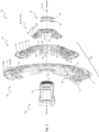
- Fig.2 shows a pinion arrangement Ap according to the present disclosure, together with a driver device Dd.
- the driver device Dd is provided in the usual way together with a freewheel device (not shown) for mounting on a rear wheel hub of the bicycle 1 in a way that transmits torque in the drive direction.
- the driver device Dd comprises a conventional toothed driving profile Pd arranged on an outer circumference.
- the driver device Dd can in particular be a standard driver device Dd, as has been widely used in the bicycle market for decades in so-called standard cassette hubs.
- the pinion arrangement Ap comprises at least one engagement profile Pe that corresponds in shape to the driving profile Pd of the driver device Dd for the torque-transmitting engagement of the pinion arrangement Ap with the driver device Dd.
- the modular structure of the pinion arrangement Ap can be seen, which includes an inboard-side final pinion device Pti, a self-supporting first pinion cluster Sc1 and an outboard-side final pinion device Pto.
- the inboard-side final pinion device Pti and the first pinion cluster Sc1 together define a cassette module Mc1.
- the pinion cluster Sc1 can be connected to the inboard-side final pinion device Pti in a connection area Ca of the inboard-side final pinion device Pti, for example by means of pins or rivets Cp.
- the connection between the inboard-side final pinion device Pti and the pinion cluster Sc1 can alternatively also be made by screwing and/or gluing in the connection area Ca.
- a screw plug device Sd which serves for mounting and fastening the pinion arrangement Ap on the driver device Dd, as well as a bearing device Db, on which the first pinion cluster Sc1 is rotatably mounted on its outboard side opposite the driver device Dd on a bearing region Sb of the bearing device Db, which is essentially designed with a cylindrical surface.
- the outboard side of the first pinion cluster Sc1 which is designed for rotatable mounting on the bearing device Db, is the outboard-side final pinion Z7.
- the outboard-side pinion Z7 of the first pinion cluster Sc1 has an inner circumferential region Ic on its inner circumference that corresponds in shape to the bearing region Sb of the bearing device Db, i.e. here also has a cylindrical surface shape (cf. Fig.10 , Fig. 13 and Fig. 15A ).
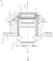
- Fig.3 shows the pinion arrangement Ap mounted on the drive device.
- the locking screw device Sd is omitted.
- the inboard-side final pinion device Pti comprises a pinion spider Sp, on which two pinion rings Rp1 and Rp2 are arranged and connected to the pinion spider Sp by means of a rivet Jr.
- Fig.3 the first pinion cluster Sc1 is only shown in dashed lines to illustrate the bearing device Db.
- the bearing area Sb of the bearing device Db which is designed with a cylindrical surface and serves for the outboard-side rotatable bearing of the first pinion cluster Sc1, with the advantages described above.
- the bearing device Db simultaneously forms a spacing unit which, when the pinion arrangement Ap is mounted on the driver device Dd, is designed to determine a relative distance Da1 in the rear axle axial direction Da between at least two pinion devices of the pinion arrangement.
- the bearing device Db is designed to determine the relative distance Da1 between the pinion spider Sp and an outboard-side final pinion device Pto.
- the bearing device Db here performs a dual function in that it serves, on the one hand, to rotatably support the first pinion cluster Sc1 on the outboard side as described above, and, on the other hand, to Setting and maintaining the relative distance Da1 between the pinion spider Sp and the outboard final pinion device Pto.
- the exact maintenance of axial relative distances such as the relative distance Da1 is important for the long-term reliability and accuracy when changing gears using the rear derailleur Rd in accordance with Fig.1 .
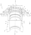
- Fig.4 shows the driving device Dd and parts of the pinion arrangement Ap mounted on the driving device Dd according to Fig. 2 and 3 .
- the bearing device Db here serves in addition to the two aforementioned functions of the outboard-side rotatable bearing Sb of the first pinion cluster Sc1 (cf. Fig.2 ) and the adjustment and maintenance of the relative distance Da1 between the pinion spider Sp and the outboard-side final pinion device Pto, also fulfils the function of an axial clamping element for mounting the pinion arrangement Ap on the driver device Dd.
- the bearing device Db in this embodiment serves to transmit an assembly clamping force in the rear axle axial direction Da between the inboard-side final pinion device Pti and the outboard-side final pinion device Pto.
- the assembly clamping force is part of a closed fastening force flow Ff that runs essentially parallel to the rear axle through the driver device Dd and the pinion arrangement Ap.
- the fastening force flow Ff is generated by the locking screw device Sd (cf. Fig.2 ) by screwing the screw plug device Sd, which has an external thread Te for this purpose, into an internal thread Ti of the drive device Dd.
- This enables the outboard-side Final pinion device Pto is pushed or pressed onto the driver device Dd and presses accordingly on the bearing device Db, which simultaneously forms a spacing unit as described above.
- the bearing device Db in turn presses against a corresponding axial stop on the inboard-side final pinion device Pti, in Fig.4 thus against the pinion spider Sp, which in turn is pressed against a corresponding axial stop Fa of the driver device Db, see also Fig.7 and 8th .
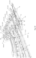
- Fig.5 illustrates another multiple function of the storage facility Db.
- the bearing device Db is not only designed to determine and maintain the relative distance Da1 between the inboard-side final pinion device, here the pinion spider Sp, and the outboard-side final pinion device Pto, but also to determine and maintain the relative distance Da2 between the inboard-side final pinion device (here pinion spider Sp) and the outboard-side final pinion Z7 of the first pinion cluster Sc1.
- the bearing device Db also takes on the task of determining and maintaining the width Da2 of the first pinion cluster Sc1.
- the first pinion cluster Sc1 is preferably manufactured with a slight width oversize, based on the width Da2.
- the pinion cluster Sc1 is supported in the rear axle axial direction Da during assembly of the pinion arrangement Ap on the drive device Dd due to of the force flow Ff (cf. Fig.4 ) axially at least slightly elastically compressed and thus fixed in the axial direction Da without play in the pinion arrangement Ap and on the driver device Dd.
- the storage facility Db is in accordance with Fig.5 furthermore designed to determine and maintain the relative distance Da3 between the outboard side of the first pinion cluster Sc1 and the inboard side of the outboard-side final pinion device, which is formed here by the second pinion cluster Sc2 (see also Fig. 2 to 4 ).
- the relative distance Da3 is ensured by the effect and width of a collar-shaped stop St, which in this embodiment is integrally formed on the bearing device Db.
- the bearing device Db in the embodiment shown is designed in an advantageous multiple function for determining all relative distances Da1, Da2, Da3 in the rear axle axial direction Da, and also for transmitting all clamping forces along the rear axle axial direction Da between the inboard-side final pinion device Pti, the outboard-side final pinion Pto, the outboard-side final pinion Z7 of the first pinion cluster Sc1 and the driver device Dd.
- the further pinion cluster Sc2 can be designed as an essentially one-piece module, for example milled from one piece.
- the further pinion cluster Sc2 can be composed of a plurality of pinion devices or pinions Z8 - Z12, wherein the plurality of pinion devices or pinions are preferably welded together, for example by laser welding.
- the plurality of pinion devices or pinions Z8 - Z12 of the further pinion cluster Sc2 are connected to one another by riveting or pinning.
- the engagement profile Pe is designed to correspond in shape to the driving profile Pd of the driver device Dd and is arranged in an axial region of at least one pinion of the further pinion cluster Sc2, here in the axial region of the pinion Z10 of the further pinion cluster Sc2. In the axial region of the pinion Z10, there is sufficient radial installation space available on an inner circumference of the pinion Z10 to arrange the engagement profile Pe there.
- the design of the further pinion cluster Sc2 as an essentially one-piece module leads in this context to the advantage that the further pinion cluster Sc2 can have pinions in which an inner diameter, in particular a tooth root diameter Dr, is smaller or considerably smaller than the outer diameter Do of the driver device Dd.
- pinion arrangements Ap can be realized with particularly small outboard pinions, here for example with the pinions Z11 and Z12, in particular with pinions that have a number of teeth equal to or less than 10.
- the arrangement of particularly small pinions with a number of teeth of 10 or less on a standard drive device Dd is again in Fig.7 shown.
- the 10-tooth pinion Z12 in particular has a root circle diameter Dr which is significantly smaller than the outer diameter Do of the driver device Dd in the area of the driving profile Pd of the driver device Dd. Due to the essentially one-piece design of the further pinion cluster Sc2, the drive torque can nevertheless also be transmitted from the smallest pinions, in particular from the 10-tooth pinion Z12, along the axial direction Da inboard via the pinion Z11 and from there to the pinion Z10. From the pinion Z10, the drive torque of the pinion Z12 can finally be transmitted to the driving profile Pd of the driver device Dd by means of the engagement profile Pe.
- the above-described design of the further pinion cluster Sc2 as a substantially one-piece module with an engagement profile Pe arranged in the area of at least one of the larger pinions Z10 of the further pinion cluster Sc2 for engagement in the driving profile Pd of the driving device Dd also allows or leads to the pinion center planes Pc11, Pc12 of at least one of the smallest pinions Z11, Z12 being positioned on the outboard side at a distance from the outboard side end face Fe of the driving device Dd, which in Fig.8 is shown.
- the installation space thus freed up on the inboard side of the pinion arrangement Ap can be used, for example, to increase the distance between the spoke flanges of a rear wheel hub of the bicycle 1, thereby improving the stability of the rear wheel Wr.
- Fig.8 further shows in detail the structure of the screw plug device Sd with its external thread Te, which is used to engage the internal thread Ti of a standard driver device, such as the driver device Dd according to Fig. 2 to 9 , is set up.
- the screw plug device Sd for accommodating particularly small pinions in this case for accommodating in particular the smallest, here 10-tooth pinion Z12, has a shaft diameter Ds which is both significantly smaller than the root circle diameter Dr of the pinion Z12, and smaller than the thread diameter Dt of the internal thread Ti of the standard driver Dd.
- the screw plug device Sd Due to this design of the screw plug device Sd and due to the design of the screw plug device Sd with the small shaft diameter mentioned and with a snap ring Rs arranged in a circumferential groove on the shaft of the screw plug device Sd in the outboard side area, the screw plug device Sd (with the snap ring Rs removed) can be opened from the inboard side, based on Fig.8 i.e. from the left, into the pinion cluster Sc2.
- the snap ring Rs is then placed in the circumferential groove of the screw plug device Sd, which allows for Screwing the screw plug device Sd into the internal thread Ti of the driver device Dd produces the essentially axial force flow Ff through the pinion arrangement Ap and the driver device Dd, which fixes the pinion arrangement Ap on the driver device Dd, as described above with regard to Fig.4 In this way, very small pinions with a number of teeth of 10 or less can be used together with a standard driving device Dd with a minimum number of parts and minimal design effort.
- Fig.8 It is also shown schematically how the further pinion cluster Sc2 is assembled as an essentially one-piece module from individual pinions Z9 - Z12. This is preferably done by laser welding, with the directions of exemplary welding laser beams in Fig.8 are indicated by block arrows Bl. In other words, this means that the laser welding of the individual pinions Z9 - Z12, which make up the pinion cluster Sc2 in the embodiment shown, takes place obliquely from the inside, whereby fillet welds Wf are formed in the areas indicated by dots.
- the individual pinions Z9 - Z12 can be firmly connected to one another to form a one-piece pinion cluster Sc2, whereby an optimal weld seam can be created due to the geometrically good accessibility of the fillet welds Wf from the radial inside.
- Fig.9 shows another embodiment of a pinion arrangement Ap.
- the above-described, outboard-side rotatable bearing Sb of the first pinion cluster Sc1 can be seen.
- the pinion arrangement described above for example according to Fig.2 , which essentially consists of the modules "inboard final pinion device Pti” (e.g. pinion spider Sp with attached ring pinions Z1, Z2), "first pinion cluster Sc1” and “outboard final pinion device Pto” (e.g. further pinion cluster Sc2), has the pinion arrangement Ap according to Fig.9 one here as Single pinion Z8 has an additional pinion device Pi. It can be seen that the single pinion Z8 can be clamped in the axial direction Da between a collar-shaped stop St of the bearing device Db and an annular stop Sr in the area of the outboard-side pinion cluster Sc2.
- the annular stop Sr can, for example, be a stop surface arranged directly or integrally on the outboard pinion cluster Sc2, or a stop surface Sr on a separate annular spacer element Ae, which is preferably made of plastic.
- the advantage of arranging a single pinion Z8 between the first pinion cluster Sc1 and the second or outboard pinion cluster Sc2 is in particular that the single pinion Z8 can be easily and inexpensively replaced if it becomes worn.
- this is also important because, according to statistical studies by the applicant, this pinion is one of the most frequently used pinions and is therefore subject to particularly high levels of wear.
- the pinion arrangement Ap is arranged in three axial areas Pa1, Pa2, Pa3 spaced apart in the axial direction Da for transmitting the drive torque to the drive device.
- the positions Pa1, Pa2, Pa3 are the axial area Pa1 of the Pinion spider Sp arranged engagement profile Pe, furthermore around the axial region Pa2 of the engagement profile Pe arranged on the outboard-side pinion cluster Sc2, and finally around the axial region Pa3 on the inner circumference of the single pinion Z8, which for this purpose also has an engagement profile Pe for torque-transmitting engagement with the driver device Dd.
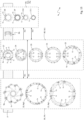
- Fig.10 shows a number of outboard pinions Z6 to Z12 of a pinion arrangement Ap according to Fig. 2 to 9 in a perspective, partially sectioned view.
- the number of teeth of the pinions in this embodiment is given in brackets behind the reference symbols Z6 to Z12.
- the pinions Z6 to Z12 are not shown in their actual rotational relative position to one another, but are rotated relative to one another for the sake of illustration so that the design of the thick-thin teeth in particular can be seen.
- the even-numbered pinions Z6 and Z8 to Z12 are thick-thin pinions as described above, the teeth of which are thus alternately assigned to a narrow or a wide tooth group, each with a different tooth width.
- the teeth of the narrow tooth group are narrow teeth that are narrower than the inner link space Wci of an inner link chain link Li of a bicycle chain Cn assigned to the pinion arrangement, while the wide tooth group comprises at least one wide tooth that is wider than the inner link space Wci of the inner link chain link, but narrower than the outer link space Wco of an outer link chain link Lo (cf. bicycle chain Cn in Fig. 11B ).
- the thick-thin sprockets ensure that the chain runs more smoothly on the sprocket occupied by the chain Cn as long as no gear shifting takes place and reduce, among other things, the unwanted lifting of the chain from the sprocket, for example in the event of strong vibrations or chain impacts.
- the thick-thin sprockets also ensure synchronization between the chain Cn and the pinion occupied by the chain Cn in such a way that inner link chain links Li specifically engage with the corresponding narrow teeth of the pinion, while outer link chain links Lo specifically engage with the corresponding wide teeth of the pinion. This enables a design of the wide and narrow teeth of the pinion that is specifically optimized for engagement with outer link chain links Lo and inner link chain links Li.
- the pinions Z6 to Z12 shown are pinions that are manufactured using a stamping and pressing process. It can be seen that the different widths of the teeth, in the case of even-numbered pinions in particular the different widths of the wide teeth Tw and the narrow teeth Tn, are created by the fact that impressions Di are typically made on an outboard-side face of the pinion, which lead to material displacement and corresponding bulges Dp on the opposite, typically on the inboard-side face of the respective pinion when the pinion is stamped and pressed.
- the indentations Di and bulges Dp can be arranged on the pinion teeth essentially centrally, relative to a circumferential direction of the respective pinion, as is the case, for example, with the pinions Z6, Z7 and Z8 according to Fig.10 the case.
- the indentations Di and bulges Dp on the pinion teeth can also be arranged laterally, in relation to a circumferential direction of the respective pinion, as is the case, for example, with the pinions Z9 to Z12.
- the arrangement of the indentations Di and bulges Dp laterally on the pinion teeth, in the example case of the Fig.10 on a respective non-load flank Fn of the respective pinion tooth, has advantages with regard to the manufacturability of the impressions Di and bulges Dp by means of the stamping-pressing process, and with regard to the load capacity and wear resistance, in particular of the load flanks Fl of the pinion teeth, which are less weakened with this arrangement of the indentations Di and bulges Dp on the non-load flank Fn.
- Fig. 11A shows, in a highly schematic manner, a part of a flat development of the circumference of an even-numbered thick-thin pinion Z3 of the pinion arrangement Ap according to the present disclosure, including a bicycle chain Cn running on the pinion Z3.
- the running of the bicycle chain Cn on the pinion Z3 is shown in Fig. 11A symbolized in the form of dashed double lines, the course of which approximately corresponds to the course of the inner surfaces of the outer link chain links Lo according to Fig. 11B corresponds.
- the base body Bm of the pinion Z3 which has a thickness Dm, is brightly dotted.
- the thickness Dm of the pinion base body Bm also corresponds to the tooth width Ww of the "normal" wide teeth Tw0 in those areas of the pinion in which there are no shift gates, i.e. neither inboard shift gates Ci nor outboard shift gates Co, see examples of inboard shift gates Ci and outboard shift gates Co in Fig.2 , Fig.9 and Fig. 12 to 14 .
- the pinion Z3 in Fig. 11A it can be a milled pinion, where the thickness Dm of the base material usually corresponds to the width Ww of the wide teeth.
- the thickness of the base material often corresponds to the width of the narrow teeth, cf. for example Fig.10 and the associated description.
- the information relating to Fig. 11A and 11B are of a fundamental nature and are therefore applicable to both milled pinions and stamped/pressed pinions.
- the "normal" wide teeth Tw0 have a tooth width which allows these wide teeth Tw to fit into an outer link Lo of a bicycle chain Cn according to Fig. 11B to engage, whereby the outer link chain links Lo have a clear width or an outer link gap Wco.
- the "normal" narrow teeth Tn0 have a tooth width which allows these narrow teeth Tn to engage in an inner link plate Li of the bicycle chain Cn.
- the inner link plate Li according to Fig. 11B have a clear width or an inner link gap Wci.
- the pinion Z3 has two (initially known) shift gate areas, namely an inboard shift gate area Ci for changing the chain Cn when shifting from a smaller, outboard-adjacent area in Fig. 11A not shown pinion to the pinion Z3, as well as an outboard shift gate area Co for changing the chain Cn when shifting from the pinion Z3 to the not shown smaller pinion adjacent in the outboard direction.
- an inboard shift gate area Ci for changing the chain Cn when shifting from a smaller, outboard-adjacent area in Fig. 11A not shown pinion to the pinion Z3
- an outboard shift gate area Co for changing the chain Cn when shifting from the pinion Z3 to the not shown smaller pinion adjacent in the outboard direction.
- Ci is even more important than with pinions without alternating thick-thin teeth Tw and Tn, since changing the chain Cn outside the shift gate areas Co, Ci can also lead to desynchronization of the chain path on the respective pinion.
- inner plate chain links Li would come to rest on wide pinion teeth Tw, whereby the wide pinion teeth Tw could not enter the inner plate chain links Li with their clear width Wci due to their width Dm.
- the chain Cn can slip on the thick-thin pinion Z3, with correspondingly disadvantageous or damaging, or even dangerous consequences when operating the bicycle.
- the pinion Z3 has Fig. 11A Stabilizing teeth Ts1, Ts2, Ts3, which are arranged in the outboard shift gate area Co or in the inboard shift gate area Ci adjacent to the outboard shift gate area Co of the pinion Z3.
- the stabilizing teeth Ts 1 and Ts3 belong to the tooth group of the narrow teeth Tn of the thick-thin pinion, i.e. to the narrow teeth Tn, while the stabilizing tooth Ts2 belongs to the wide tooth group of the teeth of the thick-thin pinion, i.e. to the wide teeth Tw.
- the teeth Tw of the wide tooth group are again marked by small circular markings
- the teeth Tn of the narrow tooth group are again marked by small square markings.
- an inboard-side chain guide surface Giln and Gi3n is located opposite the inboard-side chain guide surfaces Gi0n of the remaining "normal" narrow teeth Tn0 of the narrow tooth group in the inboard direction.
- the wide stabilizing tooth Ts2 here also together with the tooth Tn3, results in a cross-tooth chain guide dimension Dcw1 which is larger and shifted inboard compared to the "normal" cross-tooth chain guide dimension Dcw0 of wide teeth Tw0 found in areas without shift gates Ci, Co.
- a cross-tooth chain guide dimension (e.g. the cross-tooth chain guide dimension Dcn1) is a chain guide dimension or effective chain guide width that results from the interaction of, for example, an inboard-side chain guide surface of a pinion tooth (e.g. inboard-side chain guide surface Giln of the pinion tooth Ts1) with an outboard-side chain guide surface (e.g. outboard-side chain guide surface Go1n of the pinion tooth Tn1) that is closest in the circumferential direction of the pinion Z3 and in contact with an inner surface of the chain Cn.
- an inboard-side chain guide surface of a pinion tooth e.g. inboard-side chain guide surface Giln of the pinion tooth Ts1
- an outboard-side chain guide surface Go1n of the pinion tooth Tn1 e.g. outboard-side chain guide surface Go1n of the pinion tooth Tn1
- tooth-spanning chain guide dimension is the effective chain guide width or chain guide dimension Dcw1, which is determined by the interaction of the inboard-side chain guide surface Gi2w of the pinion tooth Ts2 with a circumferential of the pinion Z3 closest to the outboard side chain guide surface Go3n of the pinion tooth Tn3 in contact with the chain Cn.
- This tooth-spanning chain guide dimension Dcw1 is thus obtained by the fact that the chain rests with an inner surface of an outer plate chain link Lo on the inboard-side chain guide surface Gi2w of the pinion tooth Ts2, and next, in a circumferential direction of the pinion Z3, with an inner surface of an inner plate chain link Li on the outboard-side chain guide surface Go3n of the pinion tooth Tn3.
- a cross-tooth chain guide dimension Dcn, Dcw therefore determines the position of the chain Cn on the pinion Z3 in the rear axle axial direction Da in a respective circumferential section of the pinion Z3.
- the "normal" tooth-spanning chain guide dimension Dcn0 of the narrow teeth Tn found in areas without shift gates Ci and Co essentially corresponds to the width (viewed in the rear axle axial direction Da) of the narrow teeth Tn.
- the deflection Cd of the chain Cn inboard caused in this way by one or more of the stabilizing teeth Ts1, Ts2 and Ts3 during normal chain travel stabilizes the travel of the chain Cn on the pinion Z3 of the pinion arrangement Ap, for example and in particular in the area of an inboard shift gate Ci, see shift gates Ci in Fig.2 , Fig.9 , Fig. 12 , Fig. 13 and Fig. 14A .
- the chain Cn experiences a slight deflection Cd inboard due to the effect of one or more of the stabilizing teeth Ts1, Ts2 and Ts3, particularly in the area of the inboard shift gate Ci.
- Such a misshift would impair the uniformity and smoothness of the shifting process, disrupt the synchronous running of the chain Cn on the thick-thin teeth Tw, Tn of the pinion arrangement Ap and can, at least when shifting under load, also lead to damage to the pinion arrangement Ap and/or the chain Cn.
- the correct outboard shifting in the area of the outboard shifting gate Co is not affected by the stabilizing teeth Ts1, Ts2, Ts3 and by the deflection Cd of the chain Cn, since outboard shifting in the area of the outboard shifting gate Co is controlled by the rear derailleur Rd in accordance with Fig.1 is already initiated before the chain reaches the stabilizing teeth Ts1, Ts2, Ts3.
- the chain already takes a diagonal chain path through the areas Ri2 and Ro2 of the outboard shift gate Co (cf. Fig. 12B ), and is therefore no longer captured by the stabilizing teeth Ts1, Ts2, Ts3 on the inboard side and thus is not deflected inboard.
- a further advantage of the inboard-side chain guide surface Giln, Gi2w and Gi3n of the at least one stabilizing tooth Ts1, Ts2, Ts3 being shifted inboard is that the respective stabilizing tooth Ts1, Ts2, Ts3 thus has a larger tooth width, which increases the wear resistance of the stabilizing tooth Ts1, Ts2, Ts3.
- the at least one stabilizing tooth Ts1, Ts2, Ts3, which is preferably the case, is located in the area of a shift gate Ci, Co and thus has an outboard-side recess or a reduced tooth width on the outboard side at Ro.
- Fig. 11A is highly schematic and in particular does not correspond to the actual conditions on a pinion Z3.
- the chain Cn in Fig. 11B is shown only schematically, whereby in particular the width of the chain Cn is enlarged compared to the width of an actual bicycle chain for the sake of illustration.
- Fig. 12A and Fig. 12B show the pinion Z3 with the stabilizing teeth Ts1, Ts2 and Ts3 according to Fig. 11A in two different views.
- the pinion Z3 is in Fig. 12A diagonally from the back, i.e. from the inboard side, while the pinion Z3 in Fig. 12B looking at the front, i.e. the outboard side.
- the arrows Rdd show the drive rotation direction of the pinion when the driving load is applied by the bicycle chain Cn according to Fig.1 .
- pinion Z3 is an even-numbered thick-thin pinion
- Fig. 12A and Fig. 12B the pinion teeth belonging to the group of wide teeth Tw are again marked with circular markings, and the pinion teeth belonging to the group of narrow teeth Tn are again marked with square markings.
- the chain Cn is only shifted in the area of an outboard shift gate Co to the next smaller pinion Z4 on the outboard side (not shown in Fig. 12A and Fig. 12B , see e.g. Fig. 2 ) changes.
- the pinion Z3 has the stabilizing teeth Ts1, Ts2 and Ts3.
- the stabilizing teeth Ts1, Ts2 and Ts3 shift the chain path in the area of the stabilizing teeth Ts1, Ts2 and Ts3 by a small amount in the range of preferably tenths of a millimeter, for example by approx. 0.25 mm towards the inboard, as shown in Fig. 11A at Cd is symbolized by the double dashed line of the chain Cn.
- This straight guidance of the chain Cn which is reinforced by the stabilizing teeth Ts1, Ts2 and Ts3, prevents the chain Cn, especially after it has passed the outboard shift gate Co during the rotation of the pinion Z3 without having been switched to the next smaller pinion Z4, from undesirably switching to outboard in the area of the inboard shift gate Ci, especially in the area Ri1 with the teeth Tn1 and Tw1 there which are narrowed at the back, which reduces the straight guidance of the chain on the pinion Z3.
- Fig. 12A Clearly visible in Fig. 12A is the rear or inboard-side thickening of the stabilizing teeth Ts1 and Ts3 belonging to the group of narrow teeth Tn and the associated displacement of the inboard-side chain guide surfaces Gi1n and Gi3n towards inboard, cf.
- Fig. 11A The stabilizing tooth Ts2, which belongs to the group of wide teeth Tw, also has a rear or inboard-side thickening, which is associated with a shift of the inboard-side chain guide surface Gi2w of the stabilizing tooth Ts2 towards inboard, and a correspondingly reinforced straight guidance of the chain Cn in this area.
- the effect of the stabilizing teeth Ts1, Ts2 and Ts3, in this case in particular the "wide" stabilizing tooth Ts2, is also important when pedaling backwards. If the drive train Td of the bicycle 1 (cf. Fig.1 ) is moved backwards by the rider pedalling backwards with the pedal cranks Dc, there is a risk, particularly with the chain on one of the larger sprockets such as Z1 to Z3, that the chain will fall off the respective sprocket inboard due to the strong chain skew in this case, which can lead to damage to the drive train, in particular to the rear derailleur Rd.
- Stabilizing teeth Ts1, Ts2 and Ts3 can also be arranged on pinions of the pinion arrangement Ap other than on pinion Z3. Furthermore, the stabilizing teeth Ts1, Ts2 and Ts3 can also be used independently of one another, so for example only one or two of the stabilizing teeth Ts1, Ts2 and Ts3 can be arranged on a pinion.
- stabilizing teeth Ts1, Ts2 and Ts3 are not limited to thick-thin sprockets. Rather, stabilizing teeth such as the stabilizing teeth Ts1, Ts2 and/or Ts3 can also be used on standard sprockets without thick-thin technology, i.e. on sprockets where essentially all of the teeth are thin sprocket teeth, which can therefore engage in the inner plate space of the inner plate chain links of the bicycle chain.
- stabilizing teeth is not limited to the above-described prevention of outboard shifting at an undesirable location on a pinion.
- stabilizing teeth can also be designed with an outboard-side chain guide surface shifted outboard, or with a correspondingly enlarged and outboard-shifted chain guide dimension across the teeth, and can be used to prevent inboard shifting at an undesirable location on a pinion of a multiple pinion cassette Ap.
- stabilizing teeth is not limited to sprocket cassettes or rear wheel sprocket arrangements Ap, but can also be used for multiple sprockets Cr of a bicycle drive train Td according to Fig.1 take place.
- Fig. 13 visualizes, by way of example, a modular construction kit system for producing multiple pinion arrangements, which can be realized using the pinion arrangement according to the present disclosure.
- the assembly B1 which in the embodiment shown is formed by the inboard-side final pinion device Pti, is present in this embodiment as a pinion spider Sp with two pinion rings Z1/Rp1 and Z2/Rp2 that can be fastened to the pinion spider Sp, for example, screwed, riveted or pinned to the pinion spider, cf. Fig.2 , Fig.3 and Fig.9 with the unit shown there from pinion spider Sp and pinion rings Z1/Rp1 and Z2/Rp2 riveted to the pinion spider Sp.
- the assembly B2 which is formed here by the first pinion cluster Sc1 consists in this embodiment of the modular system of five individual pinions Z3 - Z7, cf. Fig.2 , Fig.5 , Fig.6 and Fig.9 .
- the assembly B3 which is present here in the form of another pinion cluster Sc2, comprises the pinions Z8 to Z11 in this embodiment of the modular system, and thus corresponds, for example, to the other pinion cluster Sc2 according to Fig.8 .
- the modular system shown includes the distance unit Db, which acts as an overarching link between the modules B1, B2 and B3 and which takes on an advantageous multiple function.
- the distance unit Db is similar to Fig.2 and Fig.9 shown in a quarter section.
- the function as an overarching link as well as the multiple function of the distance unit Db described in more detail below should be Fig. 13 be symbolized by the horizontal surface area F.
- the distance unit Db serves, as mentioned above, especially with regard to Fig. 2 to Fig. 5 described, initially as a rotary bearing device, by means of which the first pinion cluster Sc1 is rotatably mounted in the area of its outboard side relative to the driver device.
- the bearings for rotatable mounting on the bearing area Sb of the bearing device Db (cf. Fig. 2 to 6 and 9 ) is formed here by the outboard-side final pinion Z7, which has an inner circumferential region Ic on its inner circumference that corresponds in shape to the bearing region Sb of the bearing device Db, i.e. is essentially also formed with a cylindrical surface (cf. inner circumferential region Ic in Fig.10 and Fig. 15A ).
- the rotating bearing of the first pinion cluster Sc1 on the inner circumference Ic of the outboard side final pinion Z7 is in Fig. 13 symbolized by the double arrow A.
- outboard-side final pinion Z7 will never rotate through such a large angular range during operation as indicated by the double arrow A. Rather, the outboard-side final pinion Z7 will typically only rotate through fractions of an angular degree due to the elastic rotational deformation of the first pinion cluster Sc1, which occurs when drive torque is applied in particular to the outboard-side pinions of the first pinion cluster Cp1, for example when drive torque is applied to the pinions Z6 or Z7.
- the first pinion cluster Sc1 in the prior art is typically clamped in a force flow of the pinion arrangement running in the axial direction of the rear axle, and is therefore not rotatably mounted as in the present pinion arrangement Ap.
- the associated breakaway effects in the prior art lead to the disadvantages described in the introduction to the description, for example to undesirable noises such as cracking and squeaking when the first pinion cluster is subjected to torque, particularly on the outboard side. Due to the uncontrolled occurrence of the breakaway effects in the prior art and due to the associated sudden changes in the force flow in the first pinion cluster and due to the strong vibrations that occur, this can also impair the fatigue strength of the first pinion cluster.
- the outboard side rotatable bearing of the first pinion cluster Sc1 leads to a driving torque application of the pinions of the first pinion cluster Sc1, in particular the outboard side Pinions of the first pinion cluster Sc1, such as Z6 and Z7, mean that the first pinion cluster Sc1 can rotate in a controlled manner on the outboard side by small angles and can deform elastically without causing strong breakaway effects or vibrations in the first pinion cluster Sc1. This improves the fatigue strength of the first pinion cluster Sc1 and prevents unwanted noises such as cracking and squeaking. Due to the improved fatigue strength, the first pinion cluster Sc1 can also tend to be made thinner-walled and therefore lighter.
- the distance unit Db in addition to the above-described outboard-side rotary bearing of the further pinion cluster Sc1, also serves to determine the relative distance Da1 between the pinion spider Sp and the further pinion cluster Sc2. This is clearly shown, for example, in Fig.3 and explained in the corresponding figure description above. In Fig. 13 the relative distance Da1 between the pinion spider Sp and the further pinion cluster Sc2 is symbolically visualized by a corresponding distance arrow Da1 between the two vertical surface areas B1/Pti and B3/Sc2.
- the distance unit Db serves not only for the outboard-side rotational bearing of the first pinion cluster Sc1 and for determining and maintaining the relative distance Da1 between the pinion spider Sp and the further pinion cluster Sc2, but also for determining and maintaining the relative distance Da2 between the pinion spider Sp and the outboard-side final pinion Z7 of the first pinion cluster Sc1. This is particularly evident in Fig.5 and explained in the corresponding figure description. In Fig. 13 the relative distance Da2 between the pinion spider Sp and the outboard end pinion Z7 of the first pinion cluster Sc1 is symbolically indicated by a corresponding distance arrow Da2 is visualized between corresponding boundaries of the two vertical surface areas B1/Pti and B2/Sc1.
- the spacing unit Db in an advantageous functional combination, also takes on the task of determining and maintaining the width Da2 of the first pinion cluster Sc1 (cf. Fig.5 ).
- the distance unit Db takes over the task of determining and maintaining the relative distance Da3 between the outboard side of the first pinion cluster Sc1 and the inboard side of the second pinion cluster Sc2. This is in Fig. 2 to 4 and particularly evident in Fig.5 and explained in the corresponding figure description above.
- the relative distance Da3 between the outboard side of the first pinion cluster Sc1 and the inboard side of the second pinion cluster Sc2 is symbolically visualized by a corresponding distance arrow Da1 between the two vertical surface areas B1/Pti and B3/Pto.
- the spacing unit Db also fulfills the function of an axial clamping element for mounting the pinion arrangement Ap on the driver device Dd.
- the distance unit Db serves to transmit an assembly clamping force in the rear axle axial direction Da between the pinion spider Sp and the further pinion cluster Sc2.
- the assembly clamping force is part of a closed fastening force flow Ff through the driver device that runs essentially parallel to the rear axle. Dd and the pinion arrangement Ap, cf. Fig.4 and the corresponding figure description.
- the outboard-side final pinion Z7 of the first pinion cluster Sc1 is not clamped in the axial force flow Ff, which in the prior art leads to the disadvantages described at the beginning, particularly with regard to noise development and fatigue strength of the pinion arrangement, but remains rotatable relative to the driver device Dd with very low friction compared to the prior art and independent of the axial preload Ff.
- the spacing unit Db is made of plastic.
- the spacing unit Db is designed in an advantageous multiple function both as an outboard-side rotary bearing of the first pinion cluster Sc1 and for determining all relative distances Da1, Da2 and Da3, and also for transmitting all rear axle axial clamping forces between the pinion spider Sp, the outboard-side final pinion Z7 of the first pinion cluster Sc1 and the second pinion cluster Sc2.
- the distance unit Db also plays a role in the Fig. 13
- the pinion arrangement Ap which is designed as a modular system, therefore plays an important role in the long-term reliability of the pinion arrangement Ap and in the accuracy of gear changes using the rear derailleur Rd, and is also the central link for the modular, interchangeable assemblies B1, B2 and B3 of the modular system.
- the modular system according to Fig. 13 It should be noted that the Fig. 13 The embodiment shown is a pinion arrangement Ap in which all pinions Z1 - Z11 are thick-thin pinions. With the modular system according to Fig. 13 it will be possible to combine the latest pinion technology of the thick-thin pinions with the standard drive device Dd that has been known for decades or with corresponding standard cassette hubs, and thus to adapt it to almost every bicycle or rear wheel that has such a standard drive device Dd or a corresponding standard cassette hub. This also applies analogously to the pinion arrangements Ap according to Fig. 2 to 12B and Fig. 14A to 15C .
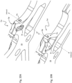
- Fig. 14A shows a further embodiment of a multiple pinion arrangement Ap with a spacing unit Db for the outboard-side rotatable bearing Sb of the first pinion cluster Sc1.
- the pinion arrangement Ap again includes an inboard-side final pinion device Pti, which here is in the form of a final pinion Z1, which is also known in the industry as a spider pinion because it takes on the function of both a pinion and the function of a supporting spider.
- the spider pinion carries both its own toothing Z1 and the inboard-side final pinion Z2 of the self-supporting, first pinion cluster Sc1.
- the pinion arrangement Ap comprises a first pinion cluster Sc1 and an outboard-side final pinion device Pto, which here again is in the form of a further pinion cluster Sc2, which is also referred to in the industry as a minicluster, especially when it is a one-piece pinion cluster, for example one welded from individual pinions.
- a screw plug device Sd which is also referred to in the industry as a lock ring, is used to fasten the pinion arrangement Ap to the driver device Dd.
- the screw plug device Sd has an external thread Te (not shown here) which can be screwed into the internal thread Ti of the driver device Dd.
- the first pinion cluster Sc1 is also rotatably mounted on the outboard side relative to the driver device Dd, for which purpose the spacing unit Db has a bearing region Sb which is preferably essentially cylindrical in shape.
- the outboard-side pinion Z9 of the first pinion cluster Sc1 has on its inner circumference an inner circumferential region Ic which corresponds in shape to the mounting region Sb of the bearing device Db, i.e. which is essentially also designed with a cylindrical surface (cf. Fig.10 , Fig. 13 and Fig. 15A ).
- the spacing unit Db in contrast to the embodiment according to Fig. 1 to 13 , in which the spacing unit Db comprises in one piece both a substantially cylindrical region and a collar-shaped stop St, the spacing unit Db in the embodiment according to Fig. 14A essentially constructed in two parts in that the collar-shaped stop St is formed here by a separate ring element.
- the spacing unit Db is provided with recesses in which vibration-damping plastic elements Ee, for example blocks made of elastomer or vibration-absorbing foam, are arranged.
- the vibration-damping plastic elements Ee come into contact with the arms As of the spider pinion Pti/Z1 and are clamped between the arms As and the spacer unit Db. In this way, unwanted vibrations can be introduced via the pinion arms As into the vibration-damping plastic elements Ee and converted into heat there.
- Such self-supporting first pinion clusters Sc1 are in the embodiments of pinion arrangements Ap according to Fig.2 , Fig.3 , Fig.5 , Fig.6 , Fig.9 , Fig. 13 , Fig. 14A and Fig. 15A
- the self-supporting pinion clusters Sc1 shown there are made up of individual pinions Z3 to Z7 ( Fig.2 , Fig.3 , Fig.5 , Fig.6 , Fig.9 , Fig. 13 ) or from individual pinions Z2 to Z9 ( Fig. 14A ), whereby these individual pinions are connected by pins (or in Fig. 15 by means of additional consoles).
- Such self-supporting pinion clusters Sc1 which can also be designed as a one-piece milled part, have the property that such pinion clusters are only connected to other parts or modules of the pinion arrangement in the area of their two inboard and outboard pinions, for example on the inboard side with a spider pinion Pti/Z1 as in Fig. 14A or with a pinion spider Sp as in Fig. 2 to 6 and Fig.9 and 13 .
- the pinions located between the inboard and outboard pinions of such self-supporting Pinion clusters are each only connected to the adjacent pinion, resulting in the self-supporting, conical or truncated cone-shaped structure of the pinion cluster.
- FIG. 14 An alternative embodiment of a distance unit compared to the distance unit Db is the distance unit Db2 in the right area of Fig. 14 .
- This spacing unit Db2 also has a vibration-damping plastic element Ee, which in this embodiment is designed as an O-ring.
- this ring-shaped plastic element Ee comes to rest in an annular, radially inner contact area of the spider pinion Pti/Z1 and can thus contribute to dampening undesirable sound vibrations of the pinion arrangement Ap.
- Fig. 14 B shows a further embodiment of a spacing unit Db3.
- This spacing unit Db3 is again formed in one piece, similar to the spacing unit Db according to Fig. 2 to 5 as well as Fig. 9 to 13 It can be seen that the distance unit Db3 has two synchronization extensions Es1, Es2.
- the first synchronization extension Es1 forms an extension of the radially inner toothing structure of the spacing unit Db3 pointing inboard in the axial direction Da, which is designed to correspond in shape to the toothing driving profile Pd of the driver device Dd.
- Standard drive devices known and used in the industry for decades such as the drive device Dd according to Fig. 2 to 9 and Fig. 14A have a toothing drive profile Pd with a rotary coding.
- the rotary coding consists in the fact that one of the drive recesses running in the axial direction Da along the driver device Dd and distributed around the outer circumference of the driver device Dd, which together form the toothing drive profile Pd, has a greater width than the remaining driving recesses.
- pinions with a correspondingly shape-correspondingly rotationally coded internal toothing profile Pe can only be attached to the driver device Dd in a certain rotational relative angular position.
- the spider pinion Pti/Z1 of the pinion arrangement Ap according to Fig. 14A has an internal tooth profile Pe which does not have such a rotary coding, since this pinion spider Pti/Z1 is used largely unchanged for one-piece pinion arrangements or pinion cassettes, apart from the pinion arrangement Ap shown.
- the rotary positioning of the pinion cassette on the driver device Dd is not important, since all shift gates of all pinions already have the correct rotary relative position to all other pinions due to the one-piece nature of the pinion cassette.
- such one-piece pinion cassettes Since the rotational positioning relative to the driving device Dd plays no role in such one-piece pinion cassettes, such one-piece pinion cassettes usually have an internal toothing profile Pe without rotational coding, and can thus be pushed onto a driving device Dd in any rotational positioning, even if this, as described above, has a rotationally coded toothing driving profile Pd.
- the pinion arrangement Ap according to Fig. 14A consists of at least two separate cassette modules Mc1 and Mc2 prior to assembly on the drive device Dd, which, due to the two cassette modules Mc1 and Mc2 existing shift gates (see e.g. shift gates Ci and Co in Fig.2 , Fig.9 , Fig. 12A /Federation Fig. 13 ) must be plugged onto the driver device Dd in a specific rotational relative angular position. However, this would not be guaranteed for the cassette module Mc1 when initially plugged onto the driver device Dd, since the internal toothing profile Pe of the spider pinion Pti/Z1 of the cassette module Mc1, as described above, does not have a rotational coding.
- the spacing unit Db3 has the synchronization extension Es1.
- the synchronization extension Es1 forms an axial extension of the rotationally coded internal toothing profile Pe of the spacing unit Db3, which is composed of engagement elevations Ep running in the axial direction Da and distributed on the inner circumference of the spacing unit Db3.
- the synchronization extension Es1 forms an axial extension of that engagement elevation Ep1 of the rotationally coded internal toothing profile Pe which has a greater width than the remaining driving elevations Ep of the internal toothing profile Pe of the spacing unit Db3, and which is thus intended for engagement in that driving recess of the toothing driving profile Pd of the driver device Dd, which correspondingly has a greater width than the remaining driving recesses of the driving profile Pd of the driver device Dd.
- the synchronization extension Es1 penetrates the rotationally non-coded internal tooth profile Pe of the spider pinion Pti/Z1 of the cassette module Mc1, and thus converts the rotationally non-coded internal tooth profile Pe of the spider pinion Pti/Z1 into a rotationally coded internal tooth profile Pe.
- the synchronization extension Es1 of the distance unit Db3 thus ensures that the cassette module Mc1 already at the beginning of the sliding onto the driver device Dd, it can only be pushed onto the driver device Dd in the specific, intended rotational relative position.
- the second synchronization extension Es2 projects in the axial direction Da inboard from the collar-shaped stop St of the distance unit Db3.
- the second synchronization extension Es2 engages in a synchronization recess Ns arranged on the outboard-side front side of the cassette module Mc1, for example on the outboard-side front side of the outboard-side final pinion Z7 of the pinion cluster Sc1.
- Examples of synchronization recesses Ns on an outboard-side front side of an outboard-side final pinion Z7 of a pinion cluster Sc1 are shown in Fig. 13 and Fig. 17C recognizable.
- the second synchronization extension Es2 ensures a correct rotational relative position between the pinion cluster Sc1 and the distance unit Db3 with its rotationally coded internal tooth profile Pe, especially during the production of the pinion arrangement, namely when assembling the pinion cluster Sc1 and spider pinion Pti/Z1 via the connecting pins Cp.
- the correct rotational relative position of the shift gates Ci and Co cf. shift gates Ci and Co in Fig.2 , Fig.9 , Fig. 12A /Federation Fig. 13
- the pinion cluster Sc1 and the spider pinion Pti/Z1 must be ensured before the pinion cluster Sc1 and the spider pinion Pti/Z1 are connected to each other by means of the connecting pins Cp.
- Fig. 15A shows an alternative embodiment of a self-supporting pinion cluster Sc1.
- the individual pinions Z3 - Z8 are not only connected to each other by connecting pins Cp 1 as in the embodiments according to Fig.2 , Fig.5 , Fig.6 , Fig.9 and Fig. 14A .
- the connection pins Cp1 are the individual pinions Z3 - Z8 in the embodiment according to Fig. 15A connected to each other via a number of Spider Consoles Cs.
- connection of the individual pinions Z3 - Z8 with the spider consoles Cs can be made using any connecting elements such as screws, rivets or pins, which are Fig. 15A to 15C are not specifically shown.
- the individual pinions Z3 - Z8 can also be connected to the spider brackets Cs by adhesives.
- the spider brackets Cs can be made of metal or alternatively of non-metallic materials, in particular of a fiber-reinforced plastic.
- the three-dimensional spatially graded spatial structure of the spider consoles Cs is recognizable, through which, viewed along a direction Da running parallel to the rear axle Ar, in this embodiment six axially spaced fastening steps Lf3 - Lf8 are formed, to which the six individual pinions Z3 - Z8 come into contact and are fastened.
- Fig. 16 shows another embodiment of a pinion arrangement Ap in a partially sectioned exploded view similar Fig.9 .
- the pinion arrangement Ap is again shown together with a rear wheel drive device Dd, onto which the pinion arrangement Ap can be mounted in a torque-transmitting manner.
- the single pinion Z8 according to Fig. 16 differs from the single pinion Z8 according to Fig. 2 to 7 and 9 insofar as the single pinion Z8 according to Fig. 16 has an engagement profile Pe on its inner circumference, which is designed in the form of a through-hole produced, for example, by punching or deep drawing.
- the width of the contact surface of the engagement profile Pe with the driver device Dd can be significantly widened or increased, which reduces the surface pressure between the engagement profile Pe and the toothing drive profile Pd arranged on the outer circumference of the driver device Dd.
- This enables better transmission of high torques between the single pinion Z8 and the driver device Dd, especially when the single pinion Z8 and/or the driver device Dd are made of relatively soft light metals instead of steel.
- the multifunctional spacer element Ems combines the function of the ring-shaped spacer element Ae between the single pinion Z8 and the further pinion cluster Sc2 (cf. Fig.9 ), and on the other hand the additional function of connecting all components of the pinion arrangement Ap to form a one-piece, manageable unit, as long as the pinion arrangement Ap is not mounted on a driving device Dd, for example on a bicycle rear wheel Wr according to Fig.1 is mounted.
- the multifunctional spacer element Ems by means of its three spring-loaded clamping arms Ac, reaches through openings Ct of the individual pinion Z8 over the width of the individual pinion Z8 as well as over the width of the collar-shaped stop St which is integrally formed on the bearing device Db.
- the three spring-loaded clamping arms Ac of the multifunctional spacer element Ems also extend beyond the width of the outboard-side final pinion Z7 of the first pinion cluster Sc1, as the spring-loaded clamping arms Ac extend through corresponding openings Ct of the outboard-side final pinion Z7.
- the multifunctional spacer element Ems has a plurality of preferably at least three clamping projections Pg on an outer circumference.
- the clamping projections Pg together define an outer diameter which has a certain excess compared to a preferably cylindrical inner shoulder Si arranged on an inner circumference of the further pinion cluster Sc2, see. Fig. 16 .
- the multifunctional spacer element Ems holds the inboard-side final pinion device Pti, the first pinion cluster Sc1, the further pinion device Pi (here in the form of the intermediate pinion Z8) as well as the outboard-side final pinion device Pto (here in the form of the further pinion cluster Sc2) and the bearing device Db together in the form of a one-piece, manageable unit, see in particular Fig. 17A .
- Fig. 17C shows how a synchronization extension Es2 of the bearing device Db, which in the axial direction Da is inboard from the collar-shaped stop St (cf. Fig. 2 to 7 and 17A ) of the bearing device Db (see also Fig. 14B ), engages in a synchronization recess Ns arranged on the outboard-side front side of the cassette module Mc1, for example on the outboard-side front side of the outboard-side final pinion Z7 of the pinion cluster Sc1, and thus determines the rotational relative position of the bearing device Db and the cassette module Mc1.
- Fig. 17C is based on a strong perspective view in order to be able to clearly see all the essential elements.
- the apparent tapering of the bearing device Db in particular in the direction of the inboard is an effect of this perspective representation.
- the bearing device Db is essentially cylindrical, which is also the case with most of the other figures, such as, for example, Fig. 17A can be removed.
- the multifunctional spacer element Ems determines the rotational relative position of the bearing device Db and the intermediate pinion Z8 or of another pinion device Pi by forming pairs of orientation projections Po which extend outboard in the axial direction Da from the collar-shaped stop St (cf. Fig. 2 to 7 and 17A ) of the bearing device Db, engage around corresponding pinion arms As of the intermediate pinion Z8 (see Fig. 17C and Fig. 16 ).
- the bearing device Db also assumes the task of centering the outboard-side final pinion Z7 of the pinion cluster Sc1 and thus the outboard side of the entire cassette module Mc1, consisting of the inboard-side final pinion device Pti and the first pinion cluster Sc1 (cf. Fig. 2 , 5 , 6 , 9 , 14A , 16 and 17A ), relative to the driver device Dd.
- the bearing device Db provides the essentially cylindrical surface-shaped bearing area Sb, on which the inner diameter of the outboard-side final pinion Z7 of the pinion cluster Sc1 comes to rest, cf. Fig. 2 to 7 as well as Fig.9 , 14A , 16 and 17A .
- radial recesses Rr on the collar-shaped stop St of the bearing device Db which correspond in shape to the spring-loaded clamping arms Ac of the multifunctional spacer element Ems, ensure that the rotational relative position between the multifunctional spacer element Ems and the bearing device Db is determined, see. Fig. 16 .
- the bearing device Db of the embodiment of the pinion arrangement Ap according to Fig. 16 and 17 can also have an inboard synchronization extension Es1, which facilitates the rotationally correct sliding of the pinion arrangement Ap onto the driver device Dd under certain conditions. This is explained in detail above in the description. Fig. 14B explained.
- Fig. 18 to 21 show schematic sectional or detailed views especially of wide pinion teeth Tw of a pinion arrangement Ap according to Fig. 2 to 17 , where the arrows Rdd indicate the driving direction of rotation of the pinion when the driving load is applied by the bicycle chain Cn, see. Fig.1 .
- the sectional or detailed views of pinion teeth shown may in particular be wide pinion teeth Tw of smaller pinions Z6 - Z12 of the pinion arrangement Ap, as shown for example in Fig.10
- the wide pinion teeth Tw according to Fig. 18 to 21 can be used in essentially the same form, but in principle on each of the pinions Zx of a pinion arrangement Ap according to Fig. 1 to 17C be realized.
- the wide pinion teeth Tw shown are preferably wide pinion teeth Tw of pinions that are manufactured using a stamping and pressing process.
- Fig. 18A The shape of the wide pinion tooth Tw shown in Fig.10 visible wide pinion tooth Tw of the pinion Z6.
- the wide teeth Tw are again marked by small circular markings, and the narrow teeth Tn are again marked by small square markings.
- the thickness Tb of the pinion base material (which preferably corresponds to the width of the narrow teeth Tn, cf. Fig.10 , also recognizable in Fig. 4 to 7 ) increased width Ww of the wide teeth Tw is produced by indentations Di being made, typically on an outboard-side face of the pinion Zx.
- indentations Di When the pinions are punched or pressed, the indentations Di lead to a material displacement and to corresponding bulges Dp on the opposite, typically on the inboard-side face of the respective pinion.
- Fig. 18C shows a variant of the wide pinion tooth Tw according to Fig. 18B .
- a counter-embossing Ec running transversely relative to a longitudinal axis of the pinion tooth running radially with respect to the pinion is introduced in such a way that it presses the two side walls Ws of the impression Di in the circumferential direction of the pinion Zx against the driving load of the bicycle chain Cn (cf. Fig.1 ) against each other.
- a pinion tooth Tw that is particularly resistant to the chain load.
- Fig. 19A shows a pinion Z8 of a further embodiment of a pinion arrangement according to Fig. 2 to 17 , looking at the outboard side face of the pinion Z8, i.e. from the same viewing direction as, for example, in Fig.1
- the pinion Z8 is again a pinion with thick-thin teeth, i.e. with narrow teeth Tn, which can enter both the outer plate gaps Wco and the inner plate gaps Wci of the bicycle chain (cf. Fig. 11B ), as well as with wide teeth Tw', which can only enter the outer plate gaps Wco, but not the inner plate gaps Wci of the bicycle chain.
- the tooth Tw3' of the pinion Z8 does not have an outboard-side impression Di, since this tooth is a nominally "wide” tooth Tw, but is located in the area of an outboard shift gate Co, cf. the also only nominally "wide” teeth Tw1, Tw3 according to Fig. 11A and Fig. 12A +B, which are also located in the area of shift gates Co, Ci.
- Such teeth Tw1, Tw3, Tw1', Tw3' which are nominally "wide” but arranged in the area of shift gates Co, Ci, typically do not have an outboard-side impression Di and accordingly also no inboard-side bulge Dp, since an inboard-side bulge Dp is present at least in the inboard-side areas Ri1, Ri2 of the shift gates Co, Ci (cf. Fig. 11-12 ) is undesirable and would disturb the transition of the chain to the adjacent pinion during the shifting process, cf. Fig. 11A and Fig. 12A
- Fig. 19B shows a wide pinion tooth Tw' of the pinion Z8 from Fig. 19A in a sectional view according to the Fig. 19A specified cutting path AA.
- Fig. 20B shows the wide pinion tooth Tw' of the pinion Z8 from Fig. 19A in an oblique view.
- the one with the wide pinion tooth Tw' according to Fig. 19A +B and Fig. 20 The principle followed and a corresponding tooth geometry can also be found on the wide pinion tooth Tw of the smallest pinion Z12 in Fig.10 .
- the inboard/outboard directions are simply reversed.
- the indentation Di is on the inboard side and the bulge Dp is on the outboard side, which serves to optimize the chain path, especially on the smallest pinion.
- the thickness Tb of the pinion base material again corresponds to the width of the narrow teeth Tn, while the width Ww' of the wide teeth Tw' is again generated by deformation during punching-pressing of the pinion Z8 by material displacement Di, Dp from the outboard side face of the pinion Z8 to the inboard side face of the pinion Z8.
- a comparison of the tooth shape of the wide tooth Tw according to Fig. 20A (see also Fig. 18A-C ) with the tooth shape of the wide tooth Tw' according to Fig. 20B (see also Fig. 19A +B) shows the different arrangement and shape, especially of the outboard-side impression Di, which leads to a correspondingly different shape of the inboard-side bulge Dp on the respective wide tooth Tw or Tw'.
- the comparatively large and wide inboard bulge Dp is formed by the wide pinion tooth Tw' according to Fig. 19A +B and Fig. 20B This is achieved by the special shape of the indentation Di and the bulge Dp, which can be clearly seen from a summary of Fig. 19A +B and Fig. 20B It can be seen that the indentation Di and the bulge Dp of the wide pinion tooth Tw' are Fig. 19A +B and Fig. 20B the non-load flank Fn of the respective pinion tooth is almost completely enclosed in the area of material displacement from outboard to inboard.
- the non-load flank Fn is located at the wide pinion teeth Tw according to Fig. 18A-C (similar to the load flank Fl) along the rear axle axial direction Da at an unchanged base position within the thickness Tb of the pinion base material.
- Fig. 21A shows a graphic overlay of the wide tooth Tw according to Fig. 18A and Fig. 20A with the wide tooth Tw' according to Fig. 19A +B and Fig. 20B .
- Fig. 21B shows a graphic overlay of the wide tooth Tw according to Fig. 18B with the wide tooth Tw' according to Fig. 19A +B and Fig. 20B .
- the wide tooth Tw' shown with a dashed line (cf. Fig. 19A +B and Fig. 20B ) has a noticeably much larger width Ww'.
- the wide tooth Tw' (dashed line in Fig. 21A ) on the side of the load flank Fl also has a greater material thickness Tm', compared to the material thickness Tm of the wide tooth Tw.
- a pinion Z8 or Zx with wide teeth Tw' according to Fig. 21A +B (cf. Fig. 19A +B and Fig. 20B ) particularly good chain guiding properties of the wide teeth Tw'.
- the wide teeth Tw' are intended for engagement exclusively in the outer plate gaps Wco of the outer plate chain links Lo.
- Fig. 19A wide tooth Ts2' positioned at the bottom of the drawing, which is located in the area of overlap between the outboard shift gate Co and the inboard shift gate Ci in the pinion Z8 shown there with 18 teeth.
- the tooth Ts2' has a particularly important chain guiding function as a stabilizing tooth for the chain run, since the pinion teeth surrounding the tooth Ts2' are narrowed or even very narrowed due to the shift gates Ci, Co located there.
- the corresponding relationships are also described in detail above in the description. Fig. 11A explained.
- the particularly important guiding task of the tooth Ts2' in the area of the shift gates Ci, Co is independent of whether an enlarged cross-tooth chain guide dimension Dcw1 is implemented on the tooth Ts2' (see in particular Fig. 11 and associated description), or whether the tooth Ts2' is a "normal" wide tooth Tw or Tw', whose width Ww or Ww' corresponds to the width Ww or Ww' of the other wide teeth Tw or Tw' of the pinion Z8 or Zx.
- the flat contact surface Fc' of these wide teeth Tw' is also considerably larger than the flat contact surface Fc of the wide pinion teeth Tw according to Fig. 18A-C , Fig. 20A and Fig. 21A +B (solid lines).
- stiffening ribs can be introduced into the embossing Di, for example in the form of counter-embossings Ec, similar to the above with regard to Fig. 18C described.
Landscapes
- Engineering & Computer Science (AREA)
- Mechanical Engineering (AREA)
- General Engineering & Computer Science (AREA)
- Chemical & Material Sciences (AREA)
- Combustion & Propulsion (AREA)
- Transportation (AREA)
- Gears, Cams (AREA)
- Gear Transmission (AREA)
- Transmissions By Endless Flexible Members (AREA)
- Devices For Conveying Motion By Means Of Endless Flexible Members (AREA)
Applications Claiming Priority (2)
| Application Number | Priority Date | Filing Date | Title |
|---|---|---|---|
| DE102022134676 | 2022-12-23 | ||
| DE102023135307.1A DE102023135307A1 (de) | 2022-12-23 | 2023-12-15 | Mehrfach-Ritzelanordnung und Baukastensystem mit Mehrfach-Ritzelanordnungen |
Publications (2)
| Publication Number | Publication Date |
|---|---|
| EP4389577A2 true EP4389577A2 (fr) | 2024-06-26 |
| EP4389577A3 EP4389577A3 (fr) | 2024-10-23 |
Family
ID=89223901
Family Applications (1)
| Application Number | Title | Priority Date | Filing Date |
|---|---|---|---|
| EP23020556.9A Pending EP4389577A3 (fr) | 2022-12-23 | 2023-12-18 | Agencement de pignon multiple et système modulaire pour agencements de pignon multiple |
Country Status (4)
| Country | Link |
|---|---|
| US (1) | US12441434B2 (fr) |
| EP (1) | EP4389577A3 (fr) |
| CN (1) | CN222629518U (fr) |
| TW (1) | TW202434491A (fr) |
Citations (1)
| Publication number | Priority date | Publication date | Assignee | Title |
|---|---|---|---|---|
| DE102010027228A1 (de) | 2009-11-04 | 2011-05-12 | Sram Deutschland Gmbh | Mehrfach-Ritzelanordnung für Fahrräder |
Family Cites Families (33)
| Publication number | Priority date | Publication date | Assignee | Title |
|---|---|---|---|---|
| US20080004143A1 (en) * | 2006-06-16 | 2008-01-03 | Shimano Inc. | Bicycle sprocket assembly |
| ITMI20071661A1 (it) * | 2007-08-09 | 2009-02-10 | Campagnolo Srl | Assieme di ruote dentate per una bicicletta |
| US8197371B2 (en) * | 2008-01-24 | 2012-06-12 | Specialized Bicycle Components, Inc. | Cogset assembly for a bicycle |
| DE102008031162B4 (de) * | 2008-07-03 | 2021-10-21 | Sram Deutschland Gmbh | Mehrfach-Kettenzahnrad für ein Fahrrad |
| US20100009794A1 (en) * | 2008-07-10 | 2010-01-14 | Douglas Chiang | Sprocket assembly |
| DE102010053597B4 (de) * | 2010-12-07 | 2021-12-02 | Sram Deutschland Gmbh | Mehrfach-Kettenradanordnung für ein Fahrrad |
| DE102011103489B4 (de) * | 2011-06-03 | 2024-12-19 | Sram Deutschland Gmbh | Hinterrad-Achsanordnung und hierfür ausgebildete Mehrfach-Ritzelanordnung |
| TWI657965B (zh) * | 2011-07-13 | 2019-05-01 | 矢倫德國股份有限公司 | 支載腳踏車變速器所用之備有小鏈輪的多鏈輪配置的傳動座體裝置 |
| US8956254B2 (en) * | 2011-08-04 | 2015-02-17 | Shimano Inc. | Bicycle sprocket assembly |
| DE102012016608B4 (de) * | 2011-08-26 | 2025-12-18 | Dt Swiss Ag | Antriebsnabe |
| US9701364B2 (en) * | 2013-05-17 | 2017-07-11 | Shimano Inc. | Bicycle sprocket and bicycle crank assembly |
| US9446815B2 (en) * | 2014-09-19 | 2016-09-20 | Vp Components Co., Ltd | Chain wheel assembly and chain wheel device using it |
| EP3037336B1 (fr) * | 2014-12-23 | 2017-04-12 | Campagnolo S.R.L. | Ensemble de pignons pour bicyclette |
| US10900547B2 (en) * | 2015-03-30 | 2021-01-26 | Sram Deutschland Gmbh | Drive arrangement for a bicycle and tool |
| DE102015210503A1 (de) * | 2015-06-09 | 2016-12-15 | Sram Deutschland Gmbh | Hinterrad-Ritzelanordnung für ein Fahrrad, insbesondere ein Pedelec |
| US10703441B2 (en) * | 2015-07-03 | 2020-07-07 | Sram Deutschland Gmbh | Drive arrangement for a bicycle |
| US10112681B2 (en) * | 2016-07-21 | 2018-10-30 | Shimano Inc. | Bicycle sprocket supporting member and bicycle sprocket assembly |
| US9868491B1 (en) * | 2016-07-21 | 2018-01-16 | Shimano Inc. | Bicycle sprocket assembly |
| ES2656783B1 (es) * | 2016-08-30 | 2018-12-11 | Rotor Componentes Tecnológicos,S.L. | Conjunto de piñones de bicicleta |
| US10577050B2 (en) * | 2016-12-26 | 2020-03-03 | Shimano Inc. | Bicycle sprocket |
| US10378637B2 (en) * | 2017-01-19 | 2019-08-13 | Shimano Inc. | Bicycle sprocket |
| US10889353B2 (en) * | 2018-01-24 | 2021-01-12 | Shimano Inc. | Bicycle rear sprocket assembly |
| US10625820B2 (en) * | 2018-01-24 | 2020-04-21 | Shimano Inc. | Bicycle rear sprocket assembly |
| US11332213B2 (en) * | 2017-05-30 | 2022-05-17 | Shimano Inc. | Bicycle rear sprocket assembly and bicycle drive train |
| TWI868953B (zh) * | 2017-05-30 | 2025-01-01 | 日商島野股份有限公司 | 自行車後輪轂總成及鏈輪支撐主體 |
| EP3533701B1 (fr) | 2018-02-28 | 2021-01-20 | SRAM Deutschland GmbH | Dispositif pignon de roue arrière pourvu de deux dispositif partiels d'une seule pièce raccordés afin de tourner ensemble |
| US10800487B2 (en) * | 2018-05-24 | 2020-10-13 | Shimano Inc. | Bicycle sprocket and bicycle drive train |
| US11072203B2 (en) * | 2018-08-22 | 2021-07-27 | Sram, Llc | Bicycle sprocket assembly |
| DE102020201889A1 (de) * | 2020-02-14 | 2021-08-19 | Sram Deutschland Gmbh | Ritzel für einen Fahrrad-Antrieb |
| DE102021000448A1 (de) * | 2020-02-22 | 2021-08-26 | Sram Deutschland Gmbh | Fahrrad-Hinterrad-Ritzelanordnung sowie Baukastensystem zur Erzeugung von Fahrrad-Hinterrad-Ritzelanordnungen |
| EP3988818B1 (fr) * | 2020-10-26 | 2025-03-05 | SRAM Deutschland GmbH | Accouplement de pignons pour bicyclette à résistance élevée à l'usure et ensemble de jeu de pignons doté d'un tel accouplement |
| IT202000025657A1 (it) * | 2020-10-29 | 2022-04-29 | Campagnolo Srl | Assieme di ruote dentate per un pacco pignoni |
| US11767080B1 (en) * | 2022-07-15 | 2023-09-26 | Shimano Inc. | Rear sprocket assembly |
-
2023
- 2023-12-18 EP EP23020556.9A patent/EP4389577A3/fr active Pending
- 2023-12-19 US US18/545,194 patent/US12441434B2/en active Active
- 2023-12-22 CN CN202323515625.5U patent/CN222629518U/zh active Active
- 2023-12-22 TW TW112150327A patent/TW202434491A/zh unknown
Patent Citations (1)
| Publication number | Priority date | Publication date | Assignee | Title |
|---|---|---|---|---|
| DE102010027228A1 (de) | 2009-11-04 | 2011-05-12 | Sram Deutschland Gmbh | Mehrfach-Ritzelanordnung für Fahrräder |
Also Published As
| Publication number | Publication date |
|---|---|
| US20240208608A1 (en) | 2024-06-27 |
| CN222629518U (zh) | 2025-03-18 |
| TW202434491A (zh) | 2024-09-01 |
| US12441434B2 (en) | 2025-10-14 |
| EP4389577A3 (fr) | 2024-10-23 |
Similar Documents
| Publication | Publication Date | Title |
|---|---|---|
| EP3181439B1 (fr) | Anneau pour fil de chaine | |
| DE102007006852B4 (de) | Fahrradkettenradbaugruppe | |
| EP3960611B1 (fr) | Système d'entraînement d'un vélo comprenant un système de plateau de pédalier multiple | |
| EP3611090B1 (fr) | Agencement de plusieurs pignons pour un dérailleur de vélo | |
| DE102010027228B4 (de) | Mehrfach-Ritzelanordnung für Fahrräder | |
| DE60319321T3 (de) | Mehrstufiger Hinterradzusammenbau für ein Fahrrad | |
| EP2415616B1 (fr) | Moyeu de roue arrière avec denture de pignon | |
| EP3450297B1 (fr) | Support de roue à chaîne et dispositif de roue à chaînes multiples | |
| EP3339158B1 (fr) | Pignon, dispositif à plusieurs pignons et entraînement par roue porteuse doté d'un tel dispositif à plusieurs pignons | |
| EP4008622B1 (fr) | Mécanisme de commutation arrière destiné à la liaison coaxiale à un cadre de bicyclette | |
| EP4011756B1 (fr) | Pignon de bicyclette doté d'une seule dent de transmission ou de prise par cavité avant de support de changement de vitesse et doté d'une dent de stabilisation dans la zone de la cavité | |
| DE202011000859U1 (de) | Fahrradkettenradanordnung | |
| EP3354553A1 (fr) | Dispositif de pignons multiples à assemblage par soudure | |
| DE202010013131U1 (de) | Fahrradkurbelanordnung | |
| DE102020005373A1 (de) | Mehrfachritzelanordnung für eine Hinterradbaugruppe für ein Fahrrad und Hinterradbaugruppe | |
| DE102021000448A1 (de) | Fahrrad-Hinterrad-Ritzelanordnung sowie Baukastensystem zur Erzeugung von Fahrrad-Hinterrad-Ritzelanordnungen | |
| DE102007062363A1 (de) | Schaltgetriebe | |
| EP3865387B1 (fr) | Plateau ou pignon pour entraînement de vélo | |
| EP4389577A2 (fr) | Agencement de pignon multiple et système modulaire pour agencements de pignon multiple | |
| DE102023135307A1 (de) | Mehrfach-Ritzelanordnung und Baukastensystem mit Mehrfach-Ritzelanordnungen | |
| EP4368411B1 (fr) | Moyeu, en particulier pour bicyclettes | |
| EP3736201B1 (fr) | Module de transmission de couple pour une bicyclette | |
| EP1446316B1 (fr) | Systeme de direction assistee motorise destine a des vehicules | |
| EP3868641B1 (fr) | Dispositif de pignons arrière de bicyclette, ainsi que système modulaire destiné à la production de dispositifs de pignons arrière de bicyclette | |
| EP4368850B1 (fr) | Moyeu, en particulier pour bicyclettes |
Legal Events
| Date | Code | Title | Description |
|---|---|---|---|
| PUAI | Public reference made under article 153(3) epc to a published international application that has entered the european phase |
Free format text: ORIGINAL CODE: 0009012 |
|
| STAA | Information on the status of an ep patent application or granted ep patent |
Free format text: STATUS: THE APPLICATION HAS BEEN PUBLISHED |
|
| AK | Designated contracting states |
Kind code of ref document: A2 Designated state(s): AL AT BE BG CH CY CZ DE DK EE ES FI FR GB GR HR HU IE IS IT LI LT LU LV MC ME MK MT NL NO PL PT RO RS SE SI SK SM TR |
|
| PUAL | Search report despatched |
Free format text: ORIGINAL CODE: 0009013 |
|
| AK | Designated contracting states |
Kind code of ref document: A3 Designated state(s): AL AT BE BG CH CY CZ DE DK EE ES FI FR GB GR HR HU IE IS IT LI LT LU LV MC ME MK MT NL NO PL PT RO RS SE SI SK SM TR |
|
| RIC1 | Information provided on ipc code assigned before grant |
Ipc: B62M 9/121 20100101ALN20240913BHEP Ipc: B62M 9/12 20060101AFI20240913BHEP |
|
| STAA | Information on the status of an ep patent application or granted ep patent |
Free format text: STATUS: REQUEST FOR EXAMINATION WAS MADE |
|
| 17P | Request for examination filed |
Effective date: 20250402 |