EP4389647A1 - Système de convoyeur aérien et procédé de surveillance d'un convoyeur aérien - Google Patents
Système de convoyeur aérien et procédé de surveillance d'un convoyeur aérien Download PDFInfo
- Publication number
- EP4389647A1 EP4389647A1 EP22215854.5A EP22215854A EP4389647A1 EP 4389647 A1 EP4389647 A1 EP 4389647A1 EP 22215854 A EP22215854 A EP 22215854A EP 4389647 A1 EP4389647 A1 EP 4389647A1
- Authority
- EP
- European Patent Office
- Prior art keywords
- monitoring
- carrier
- overhead conveyor
- control station
- station
- Prior art date
- Legal status (The legal status is an assumption and is not a legal conclusion. Google has not performed a legal analysis and makes no representation as to the accuracy of the status listed.)
- Pending
Links
Images





Classifications
-
- B—PERFORMING OPERATIONS; TRANSPORTING
- B65—CONVEYING; PACKING; STORING; HANDLING THIN OR FILAMENTARY MATERIAL
- B65G—TRANSPORT OR STORAGE DEVICES, e.g. CONVEYORS FOR LOADING OR TIPPING, SHOP CONVEYOR SYSTEMS OR PNEUMATIC TUBE CONVEYORS
- B65G9/00—Apparatus for assisting manual handling having suspended load-carriers movable by hand or gravity
- B65G9/002—Load-carriers, rollers therefor
-
- B—PERFORMING OPERATIONS; TRANSPORTING
- B65—CONVEYING; PACKING; STORING; HANDLING THIN OR FILAMENTARY MATERIAL
- B65G—TRANSPORT OR STORAGE DEVICES, e.g. CONVEYORS FOR LOADING OR TIPPING, SHOP CONVEYOR SYSTEMS OR PNEUMATIC TUBE CONVEYORS
- B65G43/00—Control devices, e.g. for safety, warning or fault-correcting
- B65G43/02—Control devices, e.g. for safety, warning or fault-correcting detecting dangerous physical condition of load carriers, e.g. for interrupting the drive in the event of overheating
Definitions
- the invention relates to an overhead conveyor system and a method for monitoring an overhead conveyor.
- Overhead conveyors are used, for example, to transport goods such as mail, packages, parcels or the like.
- Overhead conveyors can be or include bag conveyors and/or bag sorters, where bags hanging on carriers are conveyed along rails.
- Such pocket conveyors and/or pocket sorters are used, for example, in distribution centers in the courier express parcel (CEP) sector.
- Distribution centers are tasked with receiving packages, parcels and other items of goods, generally shipments, within certain dimensions and weights and distributing them to shipping directions.
- CEP distribution centers are not designed to process orders, but rather to distribute the delivered volume of packages and other shipments as completely as possible within a defined time window, during the so-called shift.
- the shipments arrive at the CEP distribution center at uncorrelated times and in a wide variety of means of transport.
- the shipments are not necessarily separated by size.
- the shipments can be unloaded automatically, semi-automatically or manually.
- the present invention solves this problem by an overhead conveyor system according to claim 1 and a method for monitoring an overhead conveyor according to claim 14.
- Advantageous embodiments are the subject of the respective subclaims.
- the monitoring unit can be used to monitor characteristic values of the overhead conveyor system, e.g. the overhead conveyor, in a simple and straightforward manner.
- the fact that the carrier or monitoring carrier can be moved or is movable to a location to be monitored or in a monitoring area means that the overhead conveyor system can be monitored relatively easily and with a relatively small number of monitoring units.
- the values recorded by the monitoring unit can be transmitted to a control station. Based on the characteristic values transmitted, a status of the overhead conveyor system and/or its functional units can be determined and a prediction can be made regarding a failure or defect or a maintenance time.
- the overhead conveyor system and any additional sensors can be connected to a network and the collected data analyzed. This can increase the performance of the overhead conveyor system and/or its functional units and, for example, significantly reduce the costs of commissioning and operation.
- the information recorded and/or obtained through analysis can support the installation, operation and maintenance of the overhead conveyors, but also the development of new product generations.
- the invention makes it possible to predict the need for service, maintenance and/or spare parts before the system fails.
- These parts can include the track, the mechanics of the carriage system, the drive mechanics, motors, electrical components and the communication hardware. It is also possible that weak points are found that could lead to failures that can be prevented by more robust design rules. The knowledge gained can be taken into account in subsequent developments.
- a failure warning can be issued before a component of the overhead conveyor, for example, fails.
- the invention can also support the commissioning of an overhead conveyor.
- the invention enables a test of the operating parameters and operating states by comparing target values with actual values. This means that corrections can still be made before commissioning, or faulty or error-prone parts can be replaced.
- the invention can also be used to detect, for example, if rails on the overhead conveyor have not been welded together correctly.
- the invention also makes it possible to reduce very costly on-site interventions. Remote maintenance is also possible. Clear limits (parameters) for the operation of the overhead conveyor system or sorter can be defined, which can be taken into account in order to detect system failures caused by incorrect configuration of the operating parameters.
- a first aspect of the invention relates to an overhead conveyor system, comprising a monitoring system and an overhead conveyor with at least one carrier that can be moved along a rail of the overhead conveyor, wherein the monitoring system has a control station and at least one monitoring unit connected to the control station for data exchange, which is configured to record a characteristic value of the overhead conveyor and/or the carrier and to transmit it to the control station.
- At least one of the monitoring units can be arranged on or near the overhead conveyor, for example on or near a functional unit, rail, switch, separation device or a station of the overhead conveyor.
- the overhead conveyor system may comprise a monitoring carrier which may be movable along a rail of the overhead conveyor and which may comprise at least one monitoring unit.
- the overhead conveyor system can have a monitoring station which can be arranged on, in or near a rail section of the overhead conveyor and which can have at least one or the monitoring unit, wherein the monitoring unit can be set up to record a value characteristic of the carrier and/or the rail section when a carrier of the overhead conveyor has moved or is being moved in the rail section
- the monitoring unit can, for example, comprise one or more of an optical camera, thermal imaging camera, photoelectric sensor, microphone and/or temperature sensor.
- the characteristic value can, for example, comprise at least one of a temperature, vibration, oscillation, acceleration, noise, image or video, deformation of the carrier and/or the overhead conveyor.
- the control station can be set up to determine a monitoring route along the overhead conveyor.
- the carrier can be set up to travel the monitoring route, whereby the monitoring route can comprise a monitoring area and/or monitoring point at least in sections or at certain points.
- the monitoring unit can be set up to to record the characteristic value at, near or in the monitoring area and/or monitoring point.
- the control station can be designed to control the carrier and/or the overhead conveyor in such a way that the carrier is or will be moved along the monitoring area.
- the control station may be configured to repeatedly and/or periodically determine and/or change the monitoring route, the monitoring area and/or the monitoring point.
- the monitoring unit can be arranged to record the characteristic value repeatedly and/or periodically.
- the control station can be set up to carry out an analysis of vibrations or oscillations, preferably of the overhead conveyor or a functional unit of the overhead conveyor, based on one or more recorded characteristic values.
- the control station can be set up to carry out the analysis taking into account accelerations measured by a monitoring unit, e.g. by a monitoring unit of the carrier.
- the control station can be configured to determine a status of the overhead conveyor and/or a functional unit of the overhead conveyor based on the recorded characteristic value and/or to carry out a prediction of a failure, anomaly, and/or maintenance of the overhead conveyor or a part of the overhead conveyor.
- Status can mean a state and/or state history.
- the monitoring system and/or the control station can have a server that can be configured to receive and/or process characteristic values recorded by the monitoring unit.
- the control station can be connected to the monitoring unit via narrowband IOT, LTE, GSM, WLAN and/or Bluetooth.
- the server can be or have a cloud server.
- the control station and/or the server can be connected to an external device for data exchange, so that the external device can access data stored on the control station and/or the server, preferably characteristic values.
- the control station can be configured to receive control commands from the external device so that remote maintenance of the overhead conveyor system can be carried out by the external device.
- the monitoring system may comprise a gateway connected to the control station, preferably the server, and the monitoring unit.
- the gateway may be or comprise an IoT gateway.
- the monitoring system can have a user interface, preferably a human-machine interface, particularly preferably a display, which can be connected to the server and/or the gateway and which can be set up to output, preferably display, characteristic values and/or status determinations, analyses and/or forecasts carried out by the control station.
- the user interface and/or the human-machine interface can be connected to the external device for data exchange and can be set up to process and/or output, preferably display, data and/or control commands received from the external device.
- the user interface can have the human-machine interface.
- the user interface and/or the human-machine interface can have a display.
- the user interface and/or the human-machine interface can, for example, have a screen with input options, e.g. via touch and/or keyboard.
- "user interface” and/or “human-machine interface” may mean any device, arrangement, system, and/or software by means of which a user can communicate with the system and/or the control station, for example, receive information and/or enter or transmit control commands.
- a control room may be provided in which a user interface may be provided and/or arranged, for example, a screen and input device.
- human-machine interface may mean a controller on a machine, e.g. a control console or the like.
- the overhead conveyor can have a discharge station that can be configured to discharge a carrier to be discharged.
- the control station can be configured to determine whether a carrier is a carrier to be discharged based on recorded characteristic values.
- the Status can mean an operating state, condition and/or status history.
- the data exchange can take place via narrowband-IOT, LTE, WLAN, GSM and/or Bluetooth. It can be provided that at least the data exchange between the control station and at least one monitoring unit can take place via narrowband-IOT, LTE, WLAN, GSM and/or Bluetooth.
- Step a) of the method can be repeated, preferably repeated periodically.
- At least one repetition of one, several or all steps of the procedure may result in the monitoring route, the monitoring area and/or the monitoring point being changed.
- At least one repetition of one, several or all steps of the procedure may result in the monitoring route, the monitoring area and/or the monitoring point being changed.
- a status of the overhead conveyor and/or the carrier can be determined. Status can mean a and/or status history. Alternatively or additionally, when evaluating the transmitted characteristic value(s), a prediction of a failure, an anomaly and/or maintenance can be carried out. Alternatively or additionally, during the evaluation, it can be checked whether transported goods have fallen out of the overhead conveyor, whereby the characteristic values can preferably include images, videos or depth data.
- a vibration can be detected several times, whereby a first vibration can be detected at a first monitoring point and a second vibration can be detected at a second monitoring point different from the first monitoring point.
- the operating state of a functional unit of the overhead conveyor may be or be varied during or before the vibration is detected.
- when moving the carrier along the surveillance route and/or in the surveillance area and/or when detecting the Oscillation may vary a speed and/or acceleration of the carrier at least partially and/or temporarily.
- the carrier when moving the carrier and/or detecting the vibration, the carrier may be moved several times and/or repeatedly along the monitoring route and/or in the monitoring area.
- At least two carriers with different loads may be or will be moved along the monitoring route and/or in the monitoring area to detect the vibration.
- a carrier is a carrier that needs to be rejected. If a carrier is a carrier that needs to be rejected, the carrier that needs to be rejected can be rejected using a rejection station on the overhead conveyor.
- a control command can be transmitted to the control station from an external device connected to the control station for data exchange and/or a human-machine interface connected to the control station for data exchange.
- the control station can control the carrier and/or the overhead conveyor based on the control command.
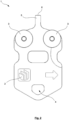
- FIGS 1 to 3 show exemplary embodiments of monitoring carriers 1 according to the invention.
- the monitoring carrier 1 has a monitoring unit 2.
- the monitoring carrier 1 can also have more than one monitoring unit 2.
- the monitoring unit 2 can be arranged on, in or near a surface or a section of the monitoring carrier 1.
- the monitoring unit 2 can be arranged in the monitoring carrier 1.
- the monitoring carrier 1 can have one, two, three, four or more rollers 3. It can be provided that the monitoring carrier 1 has one or more axes of symmetry, for example along an extension direction of the monitoring carrier 1 or perpendicular thereto, to which at least two of the rollers 3 can be arranged symmetrically.
- An overhead conveyor system 100 and/or an overhead conveyor 101 may comprise one or more carriers 1 and/or one or more monitoring carriers 1.
- a carrier 1 may comprise one, several or all of the Figures 1 to 4 shown and described features and/or advantages. In some embodiments, carriers 1 may differ from monitoring carriers 1 in that carriers do not have a monitoring unit 2.
- the carrier 1 may be or have a general or generic carrier 1 for an overhead conveyor 101. It may be provided that carrier 1 does not have to have or does not have a monitoring unit 2.
- the monitoring carrier 1 can have a coupling piece 5.
- the coupling piece 5 can be designed to connect the monitoring carrier 1 to a carrier of an overhead conveyor. It can be provided that a movement of the carrier is transmitted to the monitoring carrier 1 through the coupling piece 5, so that the monitoring carrier 1 can be moved along the overhead conveyor.
- the carrier can be arranged and/or attached to a strand, for example.
- the monitoring carrier 1 can have a magnetic coupling 6.
- the magnetic coupling 6 can be arranged on, near or in the coupling piece 5.
- the carrier of the overhead conveyor can have a corresponding magnet so that the carrier and magnetic coupling 6 can be magnetically coupled.
- the magnetic coupling 6 and/or the magnet of the carrier can be or have, for example, a permanent magnet, an electromagnet or a ferromagnet.
- the magnetic coupling 6 and the magnet of the carrier can be designed to attract each other.
- the monitoring carrier 1 can have a receptacle 4.
- the receptacle 4 can be arranged at one end of the monitoring carrier 1, e.g. a distal end.
- the receptacle 4 can be arranged at an end of the monitoring carrier 1 opposite the coupling piece 5.
- the monitoring carrier 1 can have a pocket 7.
- Receptacle 4 can be designed to hold the pocket 7.
- the monitoring unit 2 and/or another monitoring unit 2 can be arranged on, in or near the pocket 7. If one or the monitoring unit 2 is arranged on, in or near the pocket 7, the monitoring unit 2 can be removed easily and simply by detaching the pocket 7 from the Surveillance Carrier 1 must be detached and replaced, serviced and/or exchanged.
- the monitoring carrier 1 can have a sensor receptacle on or in which at least one or the monitoring unit 2 can be arranged.
- the monitoring carrier 1 can have an energy storage device 16, e.g. a battery or an accumulator.
- the energy storage device 16 can supply the monitoring unit 2 and/or the control unit 8 with energy.
- a charging unit 17 can be provided to charge the energy storage device 16. It can be provided that the energy storage device 16 can be inductively charged and/or is or will be inductively charged, for example by or with the aid of the charging unit 17. Alternatively or additionally, the energy storage device 16 can be replaceable.
- the monitoring carrier 1 can have a maintenance tool (not shown in the figures).
- the maintenance tool can be or have a brush and/or a liquid application device.
- the maintenance tool can be designed to maintain and/or clean a rail section of the overhead conveyor.
- the liquid application device can apply a lubricant, and/or e.g. oil or the like, to the rail section.
- the maintenance tool can have an ultrasound device so that the rail section can be maintained and/or cleaned by ultrasound.
- the monitoring unit 2 is designed to detect a characteristic value 10 of the monitoring carrier 1, a carrier and/or an overhead conveyor system 100.
- the characteristic value 10 of the overhead conveyor system 100 can be or have a characteristic value 10 of an element or a functional unit, e.g. a station or a part of an overhead conveyor 101.
- a functional unit of the overhead conveyor system 100 and/or the overhead conveyor 101 can be or have a monitoring station 103, a loading station 104, an unloading station 105, a pocket sorter, e.g. a matrix sorter 106, a pocket buffer 107 and/or a switch 108.
- a monitoring system or a monitoring station may be provided.
- a monitoring station 103 can be provided, which can have a monitoring unit 2.
- the monitoring station 103 can have a control unit 8.
- the monitoring station 103 can be set up to record a characteristic value 10 of a carrier and/or monitoring carrier 1 located at, in or near the monitoring station and/or traveling through the monitoring station 103.
- the monitoring station 103 can be or have a carrier testing station 103.
- the carrier testing station 103 can be set up to record a characteristic value 10 of a monitoring carrier 1 that can be moved through and/or along the carrier testing station 103, carrier 1 and/or a bag 7 transported by a carrier 1.
- a monitoring carrier 1 can have the monitoring unit 2.
- the monitoring unit 2 can alternatively or additionally be fixedly arranged on, in or near the rail, and/or in the rail section or track section and/or a functional unit.
- the characteristic value 10 of the overhead conveyor system 100 can be or have, for example, a characteristic value 10 of a monitoring station 103, a loading station 104, an unloading station 105, a pocket sorter, e.g. a matrix sorter 106, a pocket buffer 107 and/or a switch 108.
- the characteristic value 10 can also be or have a characteristic value 10 of a monitoring carrier 1 and/or a carrier.
- the characteristic value 10 can be or have, for example, a temperature, a magnetic field strength, a magnetic field direction, an acceleration, a position, a distance, a height e.g.
- the monitoring unit 2 can accordingly have one or more suitable sensors and/or detectors for detecting one or more characteristic values.
- the monitoring unit 2 may comprise a temperature sensor, a resistance sensor, a magnetic field measuring sensor, an acceleration sensor, a gyroscope, an impact sensor, a pressure sensor, a strain gauge, a position sensor, e.g. a GPS sensor, a camera, e.g.
- the monitoring unit 2 can also have more than one of the corresponding sensors. It can be provided that the monitoring unit 2, e.g. a camera, can be directed towards the ground and/or downwards. This means that, for example, objects that have fallen out of the bag can be or will be detected by the monitoring unit 2, e.g. a camera.
- the monitoring unit 2 can have a temperature sensor.
- the characteristic value 10 can be or have a temperature, for example of the monitoring carrier and/or the roller 3 of the monitoring carrier, or of a functional unit and/or a rail or rail section.
- the monitoring unit 2 can have a thermal imaging camera and the characteristic value 10 can include a temperature, heat and/or heat flow.
- the monitoring unit 2 may include a resistance sensor.
- the characteristic value 10 may include a rolling resistance and/or a friction coefficient of the roller 3.
- the monitoring unit 2 can be configured to include a magnetic field strength and/or a magnetic field direction of a magnetic field.
- the magnetic field can be configured to magnetically couple a carrier and/or monitoring carrier 1 to a carrier on either side of the overhead conveyor 100.
- the monitoring unit 2 can be or have a magnetic field measuring device.
- the monitoring unit 2 can have an acceleration sensor.
- the characteristic value 10 can include an acceleration of a carrier, a monitoring carrier 1 and/or a pocket.
- the characteristic value 10 can include an oscillation and/or vibration of a functional unit or part of a functional unit, a rail and/or rail section, a carrier, a monitoring carrier 1 and/or a pocket.
- the monitoring unit 2 can have a position sensor.
- the characteristic value 10 can include a position of a carrier, monitoring carrier 1 and/or a bag.
- the monitoring unit 2 can have a force sensor, preferably an impact sensor or a pressure sensor.
- the characteristic value 10 can comprise a deformation, a force, a pressure and/or impulse, for example of a carrier, a monitoring carrier 1, a rail element or rail section, and/or a functional unit or part of a functional unit.
- the force sensor can be designed to detect an impact of a carrier and/or a monitoring carrier 1.
- the monitoring unit 2 can have a strain gauge.
- the monitoring unit 2 can have an optical camera and the characteristic value 10 can comprise an image and/or a video.
- the optical camera can be configured to capture an image and/or video of a carrier, a monitoring carrier 1, and/or a bag.
- the optical camera can be configured to capture an image and/or video of the overhead conveyor 101, e.g. a functional unit or part of a functional unit and/or a rail or rail section.
- the monitoring unit 2 can have a microphone.
- the characteristic value 10 can include a noise, e.g. an operating noise.
- the monitoring unit can have a photoelectric sensor.
- the characteristic value 10 can include a distance of a carrier and/or monitoring carrier 1 to another carrier and/or monitoring carrier 1.
- the photoelectric sensor can be designed to include a height of a carrier and/or a monitoring carrier 1, e.g. above a reference plane.
- the photoelectric sensor can be or have a light barrier.
- the photoelectric sensor is not limited to light barriers.
- the monitoring unit 2 may comprise a position sensor.
- the position sensor may be a satellite navigation sensor, for example a GPS sensor.
- the position sensor can be set up and/or used to determine the position by means of Bluetooth, for example Bluetooth AoA (Angle of Arrival) or WLAN.
- the position of the monitoring unit 2 can be or be determined using the position sensor. If a monitoring carrier 1 has a position sensor, the position of the monitoring carrier 1 can be or be determined.
- the position can be determined, for example, by mechanical markings along the conveyor line.
- the position can be or be recorded by one or more cameras. It can also be provided to determine the position via RFID or RFID tags.
- the position sensor can comprise a suitable RFID transponder. In some embodiments, it can be provided to link a recorded characteristic value 10 to a position, for example to the position of the monitoring unit 2 when the characteristic value 10 is recorded.
- a characteristic value 10 can comprise a position and/or position data.
- an inclination, oscillation and/or pivoting of the carrier 1 and/or the monitoring carrier 1, for example relative to a rail can be or will be detected.
- an inclination, oscillation and/or pivoting of a pocket 7, for example relative to a rail can be or will be detected.
- the characteristic value 10 can include and/or represent an inclination, an angle of inclination, a pivoting or the like.
- an inclination of the carrier 1, monitoring carrier 1 and/or the pocket 7 in an ascending section or descending section, e.g. of the overhead conveyor 101 can be or will be detected.
- a back pressure in a back-up section e.g. of the overhead conveyor 101, can be or will be detected.
- the characteristic value(s) 10 can be used to carry out an analysis of a state of a corresponding functional unit or a carrier and/or monitoring carrier. It can be provided to assign or link a timestamp to each characteristic value 10 and/or to generate a timestamp when a characteristic value 10 is recorded. The timestamp can correspond to or depict the point in time at which the corresponding characteristic value 10 is recorded. Alternatively or additionally, a characteristic value 10 may include the time at which the characteristic value 10 was recorded. In some embodiments, it may be provided to determine and/or ascertain a state profile, for example as a function or progression over time. In some embodiments, it may be provided to detect defective parts based on one or more characteristic values 10. In some embodiments, a log message may be created based on one or more recorded characteristic values 10.
- the characteristic values 10 can be or will be used for remote maintenance of the overhead conveyor system 100 and/or the overhead conveyor 101.
- the recorded characteristic values 10 can be or will be transmitted to a control station 102.
- the control station 102 can be configured to perform one, several or all of the described analyses, investigations, status determinations and the like.
- the analyses, investigations, status determinations and the like performed by the control station 102 can be or will be transmitted to an external device 113 for remote maintenance.
- the external device 113 can be or include a computer device.
- the external device 113 can be or include a server and/or be or include a cloud server.
- a monitoring carrier 1 may have one or more cameras that may be used, for example, for inspection. The camera may be suitably aligned.
- the monitoring unit 2 may be or have a camera.
- the camera may be or have an optical camera, for example, and/or the characteristic value 10 may comprise an image and/or video. Alternatively or additionally, the camera may be or have an RGBD camera, a LIDAR camera or a LIDAR scanner, and/or a radar detection unit. and/or the characteristic value 10 includes depth data or distance data.
- the monitoring unit 2 can be or have a photoelectric sensor.
- the photoelectric sensor can be configured to determine a distance between two carriers, between two monitoring carriers 1 and/or between a carrier and a monitoring carrier 1. It can also be provided that distances and/or the distance between two carriers can be or can be determined alternatively or additionally by one or more of an RGBD camera, a LIDAR camera or a LIDAR scanner, and/or radar detection unit of the monitoring unit 2.
- the photoelectric sensor can be configured to detect lost transport goods, for example transport goods caught by a safety net.
- the photoelectric sensor can alternatively or additionally be configured to monitor a run of the overhead conveyor 101, e.g. a drive run, and/or to detect deformations of the current.
- the photoelectric sensor may be configured to detect wear of the rollers 3 of the carrier and/or monitoring carrier 1.
- a vibration analysis based on one or more characteristic values 10, e.g. recorded accelerations or noises.
- a vibration analysis of a rail, a rail section and/or a functional unit or a component of a functional unit of the overhead conveyor system 100 can be or will be carried out.
- Structural errors in a machine system e.g. functional units and/or parts thereof, can cause changes in the dynamic properties that can be reflected in the vibration signal.
- the vibration analysis can provide information about amplitudes and frequencies of the vibrations. This can be used to identify sources, e.g. potential or actual sources of error.
- the vibration analysis can be based on accelerations measured by a monitoring unit 2.
- accelerations can provide indications of acting forces.
- accelerations can be or will be recorded in one, two or three spatial directions. Shocks caused, e.g., by unevenness in Rail profiles can be identified, for example, as peaks in an acceleration diagram.
- a monitoring unit 2 or the monitoring unit 2 which records the accelerations is firmly attached or arranged on, near or in a rail, rail section and/or track section, and/or functional unit. It can be provided that the monitoring unit 2 can record a characteristic value 10, e.g. in this case one or more accelerations, when a carrier and/or a monitoring carrier 1 has or will travel along or at least in the vicinity of the monitoring unit 2.
- the monitoring carrier 1 can have a monitoring unit 2 which can be set up to record a corresponding characteristic value 10, e.g. in this case one or more accelerations.
- a corresponding characteristic value 10 e.g. in this case one or more accelerations.
- further data and/or operating parameters can be or will be recorded which can be included in the vibration analysis.
- the local operating state ie the operating state and/or operating parameters of components of the overhead conveyor located near the monitoring unit 2
- a load of a carrier eg the quantity, weight and/or type of goods transported by the carrier, can be recorded and/or taken into account.
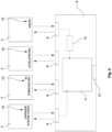
- FIG 4 shows a schematic and exemplary representation of a control unit 8.
- the monitoring carrier 1 can have a control unit 8.
- the control unit 8 can be a carrier control unit.
- the control unit 8 can be connected to a monitoring unit 2 via an interface 9.
- the control unit 8 can receive a characteristic value recorded by the monitoring unit 2 via the interface 9.
- the control unit 8 can control the monitoring unit 2 via the interface 9. If the control unit 8 is connected to more than one monitoring unit 2, a corresponding interface 9 can be provided for each.
- the control unit 8 can be connected to a force sensor, a temperature sensor, an acceleration sensor and a camera.
- the interface 9 can be or have a BUS, e.g. CAN BUS or Ethernet.
- control unit 8 can be wireless, e.g. via narrowband-IOT, Bluetooth, WLAN, GSM, Zigbee, LTE, Z-Wave, LoRaWAN, NFC, suitable low-power wide-area network (LPWAN) protocols and/or suitable other wireless protocols.
- the control unit 8 can have a data memory 11.
- the received characteristic values 10 can be stored in a Data storage 11 can be or have a database, or be part of a database.
- the database can enable local analyses and/or targeted queries by the control unit 8, external devices 113, or other computer devices connected to the database.
- At least one, several or all characteristic values 10 can include a position and/or a timestamp, and/or a position and/or a timestamp can be or will be linked to at least one, several or all characteristic values 10.
- the control unit 8 can have a computer unit.
- the computer unit can be set up to compress the characteristic values 10 and/or carry out compression 13 before, during or after the received characteristic values 10 are stored in the data storage 11. If, for example, the characteristic value 10 includes an image, the computer unit can compress the image, for example by means of JPEG compression. Videos can be compressed using suitable video encoding, e.g. MPEG. Time series data can be compressed using Deltadelta encoding, Simple-8b or XOR-based.
- Compression 13 can also include methods such as deflate, zstandard, brotli, lzma or the like. Compression methods other than those listed here are also possible. Compression 13 can reduce the memory requirement and/or the size of the characteristic value 10.
- the computer unit can be set up to carry out preprocessing during, before or after storing the received characteristic values 10, for example to generate a spectrogram from vibration data or oscillation data.
- the control unit 8 can have a radio interface 12.
- One, several or all of the recorded characteristic values 10 can be transmitted from the control unit 8 and/or the monitoring unit 2 via radio interface 12, e.g. to a control station 102, e.g. a control station 102 of an overhead conveyor system 100.
- the transmission can be carried out wirelessly via a radio connection 14, e.g. via narrowband IOT, Bluetooth, WLAN, GMS, Zigbee, LTE and/or suitable wireless protocols.
- the transmission can be carried out wired via a wired connection 15, whereby the control unit 8 and/or the monitoring carrier 1 can have a suitable interface.
- the monitoring carrier and/or the control unit 8 can have a data memory.
- Data for example recorded characteristic values 10, can be or will be stored in the data memory.
- the data stored in the data memory and/or characteristic values 10 can be transmitted via the communication interface 9, for example to the control station 102. Alternatively or additionally, it can be provided to read the data stored in the data storage, for example via a wired connection.
- a computer device e.g. a laptop, can be connected to the monitoring carrier 1, the control unit 8 and/or the data storage for data exchange via a wired connection and/or read the data storage via a wired connection. It can be provided that the monitoring carrier 1 is or will be stopped when reading the data storage, e.g. via the wired connection.
- a trigger condition can be set and/or selected for a control command (Control command: enable sensor).
- the trigger condition can be contained in the control command and/or can be specified externally. If the trigger condition is met, a command can be transmitted to a monitoring unit 2, e.g. via interface 9 (send request message), in response to which the monitoring unit 2 can measure a characteristic value 10 (measure sensor value). The detected characteristic value 10 (sensor data) can then be received (receive response message).
- a position in particular of the carrier 1 or the monitoring carrier 1, can be determined. For this purpose, a command can be transmitted to a position sensor, e.g.
- a GPS sensor or an RFID reader, or a general command to determine the position can be issued (request current position).
- the position can then be determined (position) and received (receive current position).
- the characteristic value 10, and/or if applicable the position and/or timestamp or acquisition time can be stored in the data memory 11 (store in data list). In some embodiments, it can be checked before storing whether there is enough free space in the data memory. It can be provided that the data memory is or has a ring buffer, so that the oldest data stored in the data memory can be overwritten and at least the most recent data can always be kept in the data memory.
- the characteristic value 10, and/or if applicable the position can be sent directly to the radio interface 12, and/or if applicable a corresponding wired interface.
- a gateway e.g. gateway 110, and/or control station 102.
- a check is carried out to determine whether a send limit has been reached and/or exceeded (send limit reached).
- the send limit can correspond to a maximum data size of the data to be transmitted to gateway and/or control station 102. If the send limit is not reached, some embodiments can provide for a new trigger condition to be created and/or received (set new trigger) so that a further characteristic value 10 and/or possibly a further position can be or will be recorded. It can be provided that data is or will be recorded periodically and/or the described process can be or will be carried out periodically.
- the transmission limit in some embodiments it can first be checked whether a connection, in particular a radio connection (WLAN connected?) exists. If this is the case, it can be provided to transmit the recorded characteristic value 10 and/or the position, if applicable, and/or the characteristic value 10 stored in the data memory 11 and/or positions, if applicable, to the gateway and/or control station 102 (send to gateway). If there is no radio connection, in some embodiments it can first be checked whether the transmission limit (max limit reached?) has been reached and/or the data memory is full. If the transmission limit is reached and/or the data memory is full, some of the data can be discarded (discard data). In some embodiments, the last recorded characteristic value 10 and/or the last recorded position can be discarded.
- a connection in particular a radio connection (WLAN connected?) exists. If this is the case, it can be provided to transmit the recorded characteristic value 10 and/or the position, if applicable, and/or the characteristic value 10 stored in the data memory 11 and/or positions, if applicable, to the gateway and
- the first recorded characteristic value 10 and/or the first recorded position can be discarded.
- Detected first can mean the characteristic value 10 and/or position that is the earliest and/or furthest in the past from the data stored in the data memory 11. If the transmission limit is not reached and/or the data memory is not full, some embodiments can provide for a new trigger condition to be created and/or received (set new random trigger) so that another characteristic value 10 and/or possibly another position can be detected.
- control unit 8 can be set up to carry out one or more sequences for recording a characteristic value 10.
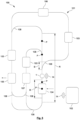
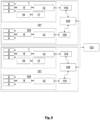
- FIGS 5 and 6 show embodiments of an overhead conveyor system 100.
- the overhead conveyor system 100 can have an overhead conveyor 101.
- the overhead conveyor system can have a monitoring system.
- the overhead conveyor system 100 and/or the monitoring system can have one or more monitoring units 2.
- the overhead conveyor system 100 and/or one of the overhead conveyors 100 can have one or more functional units, e.g. an overhead conveyor 101, one or more monitoring stations 103, one or more loading stations 104, one or more unloading stations 105, one or more pocket sorters, e.g. matrix sorters 106, one or more pocket buffers 107 and/or one or more switches 108.
- the Figures 5 and 6 The embodiments shown are merely examples.
- the Figures 5 and 6 The embodiments shown may have one, several or all of the features and/or advantages described or disclosed above and/or below.
- the overhead conveyor system 100 and/or the monitoring system can have a control station 102.
- the control station 102 can be connected to the monitoring unit 2 for data exchange.
- the monitoring unit 2 can be set up to record a characteristic value 10 of the overhead conveyor 100 and/or the carrier 1 and to transmit it to the control station 102. It can be provided that at least one of the monitoring units 2 can be arranged on or near the overhead conveyor 101, for example on or near a functional unit, rail, switch, separating device or a station of the overhead conveyor 101.
- the overhead conveyor 101 and/or the overhead conveyor system 100 can have one or more carriers for transporting goods to be transported.
- the overhead conveyor 101 can be or have a bag conveyor and/or bag sorter.
- the carriers can be designed to carry bags.
- the bags can be transport bags that can be designed or used to transport goods to be transported.
- the carrier can have one, several or all of the features and/or advantages disclosed with reference to the monitoring carrier 1. If a carrier has a monitoring unit 2, then in at least one embodiment this carrier is a monitoring carrier 1. In some embodiments, one, several or all of the monitoring carriers 1 can be set up to convey goods to be transported. In some embodiments, however, it can also be provided that one, several or all of the monitoring carriers 1 do not convey goods to be transported and/or cannot be set up to do so.
- monitoring carrier 1 and carrier can be different from one another and/or fulfill different functions.
- monitoring carrier 1 can serve exclusively to monitor the overhead conveyor system 100. If a monitoring carrier 1 has a pocket 7, it can be provided that this pocket 7 is not used to transport goods to be transported.
- the loading station 104 can be set up to introduce transport goods into the overhead conveyor 101.
- the overhead conveyor 101 can be or have a pocket conveyor, for example.
- the loading station 104 can, for example, fill and/or insert transport goods into pockets of the pocket conveyor.
- the unloading station 105 can be set up to remove transport goods from the overhead conveyor 101.
- the unloading station 105 can be set up to unload transport goods from pockets of the overhead conveyor 101.
- the bag sorter can be set up to receive bags and/or carriers from the overhead conveyor 101 in a specific order and to output them in a specific order.
- the output order can be different from the acceptance order.
- the bag sorter can be set up to change the order of bags and/or carriers and/or to put bags and/or carriers in a specific order.
- the respective orders can be or become predetermined and/or changed, even during operation.
- the bag sorter can be or have a matrix sorter 106.
- the pocket buffer 107 can be configured to buffer and/or store carriers and/or pockets. Pocket buffer 107 can be or have a dynamic memory.
- Overhead conveyor system 100 and/or overhead conveyor 101 may have one or more monitoring stations 103.
- the monitoring station 103 may have at least a monitoring unit 2.
- the monitoring station 103 can have a control unit 8.
- the control unit 8 can have one, several or all of the features and advantages described above.
- the control unit 8 of the monitoring station 103 can be similar to the carrier control unit and/or have some, several or all of the features and advantages of the carrier control unit.
- the monitoring station 103 can be set up to monitor carriers and/or monitoring carriers 1 guided through the monitoring station 103 and/or to record a characteristic value 10 of a carrier and/or monitoring carrier 1 guided through the monitoring station 103.
- the monitoring unit 2 of the monitoring station 103 can record a value 10 characteristic of the carrier, monitoring carrier 1 and/or the rail section.
- the monitoring station 103 can be arranged on or near a rail section of the overhead conveyor.
- the monitoring station 103 can be or have a carrier testing station 103.
- the carrier testing station 103 can be or have a monitoring station 103.
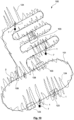
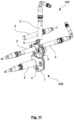
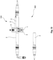
- Exemplary embodiments of a carrier test station 103 are shown in the Figures 11 to 13 shown.
- the carrier testing station 103 can be used to check a carrier of an overhead conveyor.
- the carrier testing station 103 can have a rail section along which a carrier 1 of an overhead conveyor 101 can be moved.
- the carrier testing station 103 can have at least one monitoring unit 2.
- the monitoring unit 2 can be arranged on or near a monitoring section 202 of the rail section and can be set up to record a characteristic value 10 of a carrier 1 and/or a monitoring carrier 1 and/or to read out data or characteristic values 10 stored in a data memory of the carrier 1 and/or monitoring carrier 1 when the carrier 1 or monitoring carrier 1 is or will be moved in the monitoring section.
- a carrier 1 and/or monitoring carrier 1 has moved in the rail section and/or the monitoring section 202, this may mean that the carrier 1 and/or the monitoring carrier 1 is located in the rail section and/or the monitoring section 202. This does not necessarily imply that the Carrier 1 and/or the monitoring carrier 1 must move in the rail section and/or the monitoring section 202. It can be provided to record the characteristic value 10 when the carrier 1 and/or the monitoring carrier 1 is located in the rail section and/or the monitoring section 202. If the carrier 1 and/or the monitoring carrier 1 is located in the rail section and/or the monitoring section 202, the carrier 1 and/or the monitoring carrier 1 can be or will be stopped, halted and/or braked. It can be provided to record the characteristic value 10 when the carrier 1 and/or the monitoring carrier 1 is or will be stopped, halted and/or braked in the rail section and/or the monitoring section 202.
- the monitoring section 202 can be part of the rail section.
- the monitoring section 202 can correspond to or coincide with that part of the rail section of the carrier test station 103 in, on or at which one, several or all monitoring units 2 of the carrier test station 103 can detect a characteristic value 10.
- the carrier test station may have a control unit 8.
- the control unit 8 may be or include a carrier test station control unit.
- the control unit 8 may include one, several or all of the features and advantages described above.
- the carrier test station control unit may be similar to the carrier control unit and/or include some, several or all of the features and advantages of the carrier control unit.
- the carrier test station 103 and/or the control unit 8 can have a communication interface 9.
- the carrier test station 103 can use the communication interface 9 to transmit recorded characteristic values 10 to a or the control unit 8.
- the communication interface 9 can be or have a radio interface 12.
- the carrier test station 103 and control station 102 can be connected to one another for data exchange, for example via narrowband-IOT, Bluetooth, WLAN, GSM, Zigbee, LTE, Z-Wave, LoRaWAN, NFC, suitable low-power wide-area network (LPWAN) protocols and/or other suitable wireless protocols. It can be provided that the control station 102 can control and/or regulate the carrier test station 103, or can send control commands to the carrier test station 103.
- LPWAN low-power wide-area network
- the monitoring unit 2 of the carrier test station 103 can have a camera, a photoelectric sensor.
- the camera can be or have an optical camera.
- the optical camera can be set up to record an image or video, and/or the characteristic value 10 can comprise an image or a video.
- the camera can be or have an RGBD camera, a LIDAR camera or a LIDAR scanner, and/or a radar detection unit, and/or the characteristic value 10 can comprise depth data or distance data.
- the photoelectric sensor can be, have or form a light barrier and/or a laser barrier.
- the monitoring unit 2 of the carrier testing station 103 can be or have a transponder and/or a reader.
- the transponder and/or the reader can be set up to read an RFID chip and/or RFID tag of a carrier 1, monitoring carrier 1 or a bag 7.
- the RFID chip and/or RFID tag can enable a unique identification of the carrier 1, monitoring carrier 1 or a bag 7.
- the RFID chip and/or RFID tag can contain or include a unique identification code of the carrier 1, monitoring carrier 1 or a bag 7.
- the transponder and/or a reader can be set up to receive or exchange data via NFC.
- the monitoring unit 2 of the carrier test station 103 can have a sensor that can detect a magnetic field and/or a magnetic field strength and/or magnetic field direction.
- the monitoring unit 2 of the carrier test station 103 can have a sensor that can detect vibrations and/or oscillations.
- the sensor can be or include a vibration sensor.
- the sensor can be arranged on or near the rail section and/or the monitoring section 202.
- the sensor can, for example, detect vibrations and/or oscillations that are or will be caused by a carrier 1 moving through the rail section and/or the monitoring section 202.
- the monitoring unit 2 can be or have a microphone.
- the microphone can detect ambient noise and/or noises caused by the carrier 1, e.g. running noises or roller noises, and/or noises caused by vibrations or oscillations. It can be provided to determine or ascertain vibrations and/or oscillations of the rail section and/or the monitoring section 202 based on the detected noises.
- the carrier test station 103 can have a control unit 8.
- the control unit 8 can receive data and characteristic values 10 from one, several or all sensors and monitoring units 2 of the carrier test station 103.
- the control unit 8 can be set up to control one, several or all sensors and monitoring units 2 of the carrier test station 103. If the carrier test station 103 has a braking device, the control unit 8 can be set up to control and/or regulate the braking device.
- the control unit 8 can be set up to analyze, evaluate, process, modify the data and characteristic values 10 received from the monitoring units 2 and/or create control commands, forecasts or models based thereon.
- the control unit 8 can have a data memory in which data and/or characteristic values or the like are or can be stored.
- the control unit 8 can be connected to the control station 102 for data exchange.
- the control unit 8 can be connected to the control station 102 via the communication interface 9.
- the control unit 8 can transmit the data and characteristic values 10 received from the monitoring units 2, and/or the analyses, evaluations, forecasts, control commands, models and/or modified data or modified characteristic values created by the control unit 8 based thereon to the control station 102.
- the control station 102 can query data and characteristic values 10, and/or the analyses, evaluations, forecasts, control commands, models and/or modified data or modified characteristic values created by the control unit 8 based thereon from the control unit 8.
- the control station 102 can directly access the sensors and monitoring units 2 of the carrier test station 103, and/or possibly the braking device of the carrier test station 103, and/or can be directly connected to them for data exchange.
- the control station 102 can receive data and characteristic values 10 from one, several or all sensors and monitoring units 2 of the carrier test station 103.
- the control station 102 can be set up to control one, several or all sensors and monitoring units 2 of the carrier test station 103. If the carrier test station 103 has a braking device, the control station 102 can be set up to control and/or regulate the braking device.
- the Control station 102 can be configured to analyze, evaluate, process, modify the data and characteristic values 10 received from the monitoring units 2 and/or create control commands, forecasts or models based thereon.
- a first monitoring unit 2 can be arranged such that it can detect a characteristic value 10 of the carrier 1 and/or of a bag 7 transported by the carrier 1 from a first side.
- a second monitoring unit 2 can be arranged such that it can detect a characteristic value 10 of the carrier 1 and/or of the bag 7 from a second side, which can be different from the first side.
- At least one monitoring unit 2 can be arranged laterally on one side of the monitoring section 202, and at least one further monitoring unit 2 can be arranged opposite the side. It can be provided that the carrier 1 can be moved between two monitoring units 2 in the monitoring section 202.
- the monitoring units 2 can, for example, be arranged in such a way that they can laterally detect one or the rollers of the carrier 1, the body of the carrier 1, the head piece 5 and/or the magnetic coupling 6 of the carrier 1, the holder 4 of the carrier 1 and/or the pocket 7, and/or can detect a characteristic value 10 of these.
- a monitoring unit 2 can be arranged on or at an upper side of the monitoring section 202.
- the carrier 1 can be movable in the monitoring section 202 below the monitoring unit 2.
- the monitoring unit 2 can, for example, be arranged in such a way that it can detect one or the rollers of the carrier 1, the body of the carrier 1, the head piece 5 and/or the magnetic coupling 6 of the carrier 1, and/or the pocket 7 from above, and/or can detect a characteristic value 10 of these.
- the monitoring unit 2 can be designed to detect a position and/or dimension of the carrier 1 and/or a bag 7 transported by the carrier 1.
- the monitoring unit 2 can have a camera or a photoelectric sensor for this purpose.
- the photoelectric sensor can form a light barrier or laser barrier and detect when a carrier 1 or a bag 7 passes through the light barrier or laser barrier. passes through or is in their area.
- a carrier 1 or a bag 7 and their position can be identified in an image or video recorded by an optical camera.
- the position of the carrier 1 or the bag 7 can be determined from depth data recorded with a LIDAR camera or an RGBD camera.
- an RFID chip of a carrier 1 or a bag 7 can be read and it can be concluded that the carrier 1 or the bag 7 is located at the monitoring unit 2.
- the monitoring unit 2 can be configured to detect one or more rollers 3 of the carrier 1 and/or a state of one or more rollers 3 of the carrier 1.
- the monitoring unit 2 can have a camera for this purpose.
- a state of one or more rollers 2 can be determined using an image or video recorded by an optical camera.
- the monitoring unit 2 can be set up to detect a magnetic field strength and/or magnetic field direction of a coupling piece 6 and/or a magnetic coupling 6 of the carrier 1.
- the monitoring unit 2 can have a suitable sensor for this purpose. For example, based on the detected magnetic field and/or its magnetic field strength and/or magnetic field direction, a state or presence of a magnetic coupling and/or a coupling between the magnetic coupling and the driver can be determined.
- the monitoring unit 2 can be configured to detect and/or read an RFID chip of the carrier 1.
- the monitoring unit 2 can have a transponder or a suitable reader for this purpose.
- the monitoring unit 2 can be set up to detect transport goods that have fallen down on or near the rail section and/or monitoring section 202.
- the transport goods that have fallen down can have fallen out of a pocket 7 of a carrier 1.
- the monitoring unit 2 can be set up to detect objects hanging out of a pocket 7 transported by the carrier 1 and/or a loading state of the pocket 7.
- a photoelectric Sensor form a light barrier or laser barrier and detect when a carrier 1 or a bag 7 passes through the light barrier or laser barrier or is in its area, or whether an object is in a predetermined area, e.g. to the side of a bag 7 or below the monitoring section 202.
- an image, video and/or depth data recorded by a camera can be used to determine whether a transport item has fallen down on or near the rail section and/or monitoring section 202 and/or whether an object is hanging out of a bag 7 transported by the carrier 1.
- a loading state of the bag 7 can be determined using an image, video and/or depth data.
- the monitoring unit can be configured to detect an acceleration of the carrier 1 and/or a bag 7 transported by the carrier 1. For example, a speed and/or acceleration of a carrier 1 and/or a bag 7 can be determined using multiple images or depth data, a video and/or multiple light barriers.
- the monitoring unit 2 may be configured to detect a vibration or oscillation of the monitoring section 202.
- the carrier inspection station 103 and/or the monitoring unit 2 of the carrier inspection station 103 can have one or more cameras.
- the camera can be a camera that can be set up to capture an image, video or depth data of a carrier 1, a monitoring carrier 1 and/or a bag 7 transported by the carrier 1 when the carrier 1 and/or monitoring carrier 1 is or is being moved in the monitoring section 202.
- a first camera 2 can be arranged such that it can capture an image, video or depth data of the carrier 1, the bag 7 and/or monitoring carrier 1 from a first side.
- a second camera 2 may be arranged such that it can record an image, video or depth data of the carrier 1, the pocket 7 and/or the monitoring carrier 1 from a second side, which may be different from the first side, when the carrier 1 and/or monitoring carrier 1 is or is being moved in the rail section.
- a camera is directed downwards, e.g. towards the ground, in order to detect a dropped transport item and/or a
- the net can be or have a safety net or a catch net for fallen transport goods, for example.
- a monitoring unit 2 in particular a monitoring unit 2 of a monitoring station 103 and/or carrier checking station 103, can detect whether transport goods are hanging out of a pocket 7.
- the monitoring station 103 can be set up to check whether transport goods are hanging out of a pocket 7 transported by a carrier 1 through the monitoring station 103 and/or along the monitoring section 202.
- the control station 102 can be set up to check whether transport goods are hanging out of a pocket 7 transported by a carrier 1 through the monitoring station 103 and/or along the monitoring section 202.
- the monitoring station 103 and/or the control station 102 can be configured to check whether parts of a carrier 1 and/or monitoring carrier 1 moved through the monitoring station 103 and/or along the monitoring section 202 have broken off and/or whether they are damaged.
- a monitoring unit 2 in particular a monitoring unit 2 of a monitoring station 103, can measure a pocket thickness of a pocket 7 transported by a carrier. The measured pocket thickness can be compared with a minimum thickness for the transported goods.
- the carrier test station 103 and/or monitoring unit 2 can be configured to read an RFID chip of a carrier 1 and/or monitoring carrier 1 moved through the carrier test station 103.
- the monitoring unit 2 can be or have an RFID reader, for example.
- the RFID chip can include a unique identifier of the carrier 1 and/or monitoring carrier 1. Based on the RFID chip, the position of the carrier 1 and/or monitoring carrier 1 in the overhead conveyor system 100 can be determined, for example by the carrier test station 103 and/or the control station 102.
- a recorded characteristic value 10 can be assigned to or linked to a carrier 1 and/or monitoring carrier 1 or
- the RFID chip can include information about a transport item transported by a carrier 1, for example a transport item transported in a bag 7.
- the carrier test station 103 and/or the monitoring unit 2 can be configured to detect a magnetic field between the carrier 1 and/or the monitoring carrier 1 and a magnetic carrier, so that the carrier test station 103 and/or the control station 102 can determine a strength of the magnetic coupling.
- the carrier test station 103 and/or the control station 102 can carry out the corresponding analyses, investigations or determination of the states based on the characteristic values 10 detected by the monitoring unit 2.
- the rail section and/or the monitoring section 202 can consist at least partially and/or in sections of a transparent material or have such a material.
- the rail section in the area of the carrier testing station 103 and/or in the monitoring section 202 can consist at least partially and/or in sections of a transparent material or have such a material.
- at least one monitoring unit 2, e.g. a camera, is arranged in such a way that it can be directed at the transparent material.
- the monitoring unit 2 can, for example, be set up and/or aligned in such a way that it can detect the rollers 3 of the carrier 1 and/or monitoring carrier 1 and/or a state of the rollers 3 of the carrier 1 and/or monitoring carrier 1 when it has been or is being moved in the rail section.
- the carrier testing station 103 can have a braking device.
- the braking device can be designed to brake and/or stop the carrier 1 in the monitoring section 202.
- the braking device can be arranged on, near or in the monitoring section 202.
- the braking device can be arranged such that at least one monitoring unit 2 can record a characteristic value 10 of a carrier 1 braked or stopped by the braking device.
- the braking device may comprise at least one plunger.
- the plunger may be adjustable between a first position and a second position.
- the plunger can be adjustable essentially perpendicular to an extension direction of the rail section and/or the monitoring section 202. If the plunger is in the first position and/or is or is adjusted to the first position, the plunger can stop or at least decelerate a carrier 1 guided along the rail section and/or monitoring section 202. For example, the plunger can contact the carrier 1 in the first position and thus stop or at least decelerate it.
- the plunger can be or will be retracted relative to the first position in such a way that the plunger cannot contact a carrier 1 guided along the rail section and/or monitoring section 202. If the plunger is or is adjusted from the second position to the first position, a carrier 1 stopped and/or braked by the plunger in the first position can be released and/or can be or will be able to move again.
- the braking device can have a rocker.
- the rocker can be mechanically coupled to the plunger and can be designed to adjust the plunger between the first position and the second position.
- the braking device can have a drive for adjusting the plunger and/or the rocker.
- the drive can be or have an electric motor, for example.
- the drive can be connected to the control unit 8 and/or the control station 102 in such a way that the drive can be controlled by the control unit 8 and/or the control station 102.
- a carrier 1 in the monitoring section 202 is or will be stopped and/or at least braked by the braking device, and a or the monitoring unit 2 can detect a characteristic value 10 of the stopped and/or at least braked carrier 1 and/or a pocket 7. It can be provided that the carrier 1 is or will be stopped and/or at least braked before a or the characteristic value 10 is or will be detected. It can be provided that the carrier 1 is or will be released and/or moved on again after the characteristic value 10 has been detected.
- control station 102 controls the carrier test station 103 and/or instructs one to record one or more characteristic values 10 of one or more carriers 1, monitoring carriers 1 and/or pockets 7.
- the Control station 102 may, in some embodiments, alternatively or additionally control and/or regulate the braking device.
- the braking device can be or comprise a singling device or can serve to singulate carriers 1.
- the carrier inspection station 103 can be combined with a singling station and/or can be used or can serve to singulate carriers 1.
- the braking device can have two tappets.
- the tappets can be mechanically coupled to the rocker.
- the tappets can be adjusted in opposite directions.
- the rail section and/or the monitoring section 202 can be or have a gradient. It can be provided that a carrier 1 can be moved in the rail section and/or the monitoring section 202 due to its weight. It can be provided that a carrier 1 in the rail section and/or the monitoring section 202 is or will be moved only due to its weight. In some embodiments, no run can be arranged and/or provided in the rail section and/or the monitoring section 202. In some other embodiments, a run can be provided alternatively or additionally. The run can be or will be coupled to the carrier 1 and/or monitoring carrier 1 via a driver. The run can be set up to move and/or move the carrier 1 and/or monitoring carrier 1 in the rail section and/or the monitoring section 202 at least in sections.
- the overhead conveyor 101 and/or the overhead conveyor system 100 can have a discharge station (not shown in the figures).
- the discharge station can be set up or serve to discharge a carrier 1 to be discharged and/or to remove it from the overhead conveyor 101 and/or the overhead conveyor system 100.
- the carrier testing station 103 can have a control unit 8, which can be set up to evaluate the characteristic values 10 recorded by the carrier testing station 103 and to determine based on this whether a carrier 1 is a carrier to be discharged.
- the control station 102 can be set up to evaluate the characteristic values 10 recorded by the carrier testing station 103. Evaluate values 10 and determine based on them whether a carrier 1 is a carrier to be ejected.
- the method can be carried out with or by a carrier test station 103.
- a carrier test station 103 can be configured to carry out one, several or all steps of the method.
- the method can be carried out with a carrier test station 103.
- a carrier test station 103 can be configured to carry out one, several or all steps of the method.
- the carrier 1 can be stopped at least temporarily and/or in sections when detecting the characteristic value 10 and/or when reading out the characteristic value 10 or the data.
- the carrier 1 When detecting the characteristic value 10 and/or when reading out the characteristic value 10 or the data, the carrier 1 can be or will be moved at least temporarily and/or sectionally in the monitoring section 202.
- a position and/or dimension of the carrier 1 and/or of a pocket 7 transported by the carrier 1 can be recorded during the recording and/or reading.
- one or more rollers 3 of the carrier 1 and/or a state of one or more rollers 3 of the carrier 1 can be recorded during the recording and/or reading.
- a magnetic field strength and/or magnetic field direction of a coupling piece 5 and/or a magnetic coupling 6 of the carrier 1 can be recorded during the recording and/or reading.
- an RFID chip of the carrier 1 can be recorded and/or read during the recording and/or reading.
- a transport item that has fallen down on or near the rail section and/or monitoring section 202 preferably a transport item that has fallen out of a pocket 6 of a carrier 1
- an acceleration of the carrier 1 and/or a bag 7 transported by the carrier 1 can be detected.
- the recorded and/or read characteristic value 10, and/or the read data can be evaluated by a control unit 8. In some embodiments, it can be determined during or after the evaluation whether the carrier 1 is a carrier 1 to be ejected.
- the carrier 1 and/or monitoring carrier 1 can be configured to be or will be moved along the overhead conveyor 101.
- the carrier 1 and/or the monitoring carrier 1 can in particular be movable along a monitoring route R.
- the monitoring route R can correspond to a section and/or part of the overhead conveyor 101. In some embodiments, the monitoring route R can also correspond to the entire route of the overhead conveyor 101.
- the monitoring carrier 1 can be configured to record a characteristic value 10 at or near a monitoring point P and/or at least in sections or point by point in an area B.
- the area B can be or have a monitoring area B. Area B can mean a monitoring area B.
- the monitoring carrier 1 and/or the monitoring unit 2 can be configured to record a characteristic value 10 continuously, e.g. continuously in the area B.
- the monitoring carrier 1 can be moved to the monitoring point P and record one or more characteristic values 10 at the monitoring point P. Alternatively or additionally, the monitoring carrier 1 can be moved in the area B and record one or more characteristic values 10 in the area B. More than one monitoring point P and/or area B can be provided. A monitoring point P can be located in an area B.
- Monitoring point P and/or area B can be located in the monitoring route R and/or be part of it. More than one monitoring point P and/or more than one area B can also be provided.
- the area B can also comprise one or more functional units, sections or parts of the overhead conveyor 101.
- the area B in the case of the Figure 5 shown embodiment, the loading station 104 and/or switch 108. It can thus be provided that the monitoring carrier 1 can also record the characteristic value 10 on, in or at the corresponding part of the overhead conveyor and/or functional unit, in the example, the loading station 104 and/or switch 108.
- the monitoring carrier 1 can also record one or more characteristic values 10 when driving through a corresponding part of the overhead conveyor and/or functional unit, in the example, the loading station 104 and/or switch 108.
- the monitoring carrier 1 can also record one or more characteristic values 10 when driving through a corresponding section of the overhead conveyor.
- the monitoring point P may be arranged on, in or at a section, part and/or functional unit of the overhead conveyor 100.
- the monitoring point P can be arranged on, at or in a switch 108 of the overhead conveyor 101.
- one or the monitoring point P can also be arranged along the route of the overhead conveyor 101.
- dynamic routing can be provided.
- the monitoring unit 2 can record one or more characteristic values 10 during operation, eg when one or more carriers 1 and/or monitoring carriers 1 have been or are being moved, eg through monitoring point P and/or area B.
- static routing be provided.
- a monitoring carrier 1 which can detect the corresponding characteristic value(s) 10 can stop, e.g. at a monitoring point P and/or in an area B.
- the monitoring carrier 1 has detected one or more characteristic values 10, these can be transmitted to the control station 102, for example via radio connection 14 and/or a wired connection (not shown in the figures).
- the characteristic value 10 can be transmitted by or from the control unit 8, e.g. a carrier control unit.
- At least one functional unit and/or a route section can have at least one monitoring unit 2. If a functional unit and/or a route section has a monitoring unit 2, it can be provided that this can also have a control unit 8. Alternatively or additionally, a monitoring unit 2, and in some embodiments also a control unit 8, can be arranged on, near or in a functional unit and/or a route section.
- the monitoring unit 2 can be set up to record a characteristic value 10 of the corresponding functional unit and/or the route section, and/or a carrier or monitoring carrier 1 passing by or located nearby.
- a monitoring unit 2 arranged on, in or near a route section can be part of a monitoring station 103.
- a monitoring station 103 can have or be a monitoring unit 2 arranged on, in or near a route section.
- a monitoring unit 2 of a functional unit and/or a route section, and/or a monitoring unit 2 arranged on, near or in a functional unit and/or a route section has recorded one or more characteristic values 10, this can be transmitted to the control station 102, for example via a radio connection 14 and/or a wired connection 15.
- the characteristic value 10 can be transmitted by one or the control unit 8 of the functional unit and/or the route section, and/or a monitoring unit 2 arranged on, near or in the functional unit and/or the control unit 8 arranged on the route section.
- the control station 102 can have a computer unit 116.
- the control station 102 and/or the computer unit 116 can be set up to specify and/or determine the monitoring route R, monitoring points P and/or areas B.
- the control station 102 and/or the computer unit 116 can be set up to control the monitoring carrier 1 and/or the overhead conveyor 101 in such a way that the monitoring carrier 1 is or will be moved along the monitoring route R, so that one or more characteristic values 10 are or can be recorded by the monitoring unit 2 of the monitoring carrier 1.
- control station 102 and/or the computer unit 116 can be set up to control the monitoring station 103 and/or a monitoring unit 2 fixedly arranged on, near or in the rail, rail section or track section and/or a functional unit in such a way that it can record one or more characteristic values 10.
- a monitoring route R can first be determined by the control station 102. It can be provided that the control station 102 can determine one or more areas B and/or monitoring points P. The monitoring carrier 1 can then be moved to the monitoring route R and/or along the monitoring route R. It can be provided that the monitoring carrier 1 is moved to or in the area B and/or monitoring point P. One or more characteristic values 10 can then be recorded with the monitoring unit 2 of the monitoring carrier 1 at the monitoring point P and/or at or in the area B. The recorded characteristic value 10 can be stored in a data memory 11 of the monitoring carrier 1 and/or transmitted to the control station 102 via a communication interface 9 of the monitoring carrier 1.
- a (in some embodiments stationary) monitoring unit 2 and/or a monitoring station 103 can be provided on, at or in the overhead conveyor.
- a carrier 1 and/or monitoring carrier 1 can be provided on or in an area B and/or monitoring point P which is Monitoring unit 2 and/or monitoring station 103 can be detected, moved or will be, in some embodiments at the instigation or controlled by the control station 102.
- One or more characteristic values 10 can then be detected with the monitoring unit 2 (on, at or in the overhead conveyor) and/or monitoring station 103 of the monitoring carrier 1.
- the detected characteristic value 10 can be stored in a data memory of a control unit 8 and/or the monitoring station 103, and/or transmitted to the control station 102 via a communication interface 9 of the monitoring carrier 1.
- the determination of the monitoring route R, the monitoring area B and/or the monitoring point P can be carried out, for example, on the basis of a current and/or predicted operating state.
- An operating state can include, for example, information, data or values relating to a throughput, number of errors or the like. It can be provided to collect and/or record data in certain operating states of the overhead conveyor 101 and/or at certain "points of interest", or interesting, important or critical points of the overhead conveyor 101, along the overhead conveyor 101 and/or its functional units, components and/or stations.
- the carrier and/or monitoring carrier 1 can be slowed down and/or stopped.
- a characteristic value 10 has been recorded at or in a region B and/or monitoring point P, another characteristic value 10, e.g. the same size, is recorded again and/or repeatedly at a later point in time. In this way, temporal progressions of the characteristic value can be or will be determined. In some embodiments, one or more characteristic values 10 can be or will be recorded periodically.
- control station 102 can vary or change the monitoring route R, areas B and/or monitoring points P, for example depending on predetermined rules or based on control commands.
- the monitoring route R, monitoring area B and/or the monitoring points P can be changed periodically or repeatedly. However, it can also be provided that at least one further and/or repeated detection a characteristic value 10, the monitoring route R, area B and/or the monitoring point P determined by the control station 102 remains unchanged.
- the control station can be set up to carry out an analysis of vibrations or oscillations, preferably of the overhead conveyor or a functional unit of the overhead conveyor, based on one or more recorded characteristic values.
- the control station can be set up to carry out the analysis taking into account characteristic values 10 recorded by one or the monitoring unit 2 of the monitoring carrier 1, e.g. measured accelerations.
- the analysis can be carried out taking into account characteristic values 10 recorded by one or the monitoring unit 2 arranged on the overhead conveyor 101 and/or a monitoring station 103.
- the control station 102 can be set up to determine a status of the overhead conveyor 101 and/or a functional unit of the overhead conveyor 101 based on the recorded characteristic value 10.
- the status can correspond to an operating state or the operating state.
- the control station 102 can carry out a prediction of a failure, anomaly, and/or maintenance of the overhead conveyor 101 or a part of the overhead conveyor 101, e.g. a functional unit. It can be provided that the control station 102 can take into account an operating state, system parameters, and/or environmental parameter data such as temperature, humidity, air pressure and the like when predicting a failure, an anomaly or maintenance.
- the control station 102 can define, determine or ascertain maintenance measures based on the prediction.
- FIG. 7 shows an embodiment of an overhead conveyor system 100.
- the overhead conveyor system can have one, several or all of the features and/or advantages described or disclosed above and/or below.
- the overhead conveyor system 100 and/or the monitoring system can have a server 109.
- the overhead conveyor system 100 and/or the monitoring system can have a gateway 110.
- the overhead conveyor system 100 and/or the monitoring system can have a human-machine interface 111.
- the gateway 110 can be set up to receive data from a monitoring unit 2 and/or control unit 8 and/or to send it to a monitoring unit 2 and/or Control unit 8.
- the gateway 110 can be configured to receive data from server 109 and/or send it to server 109.
- the gateway 110 can be configured to receive data from human-machine interface 111 and/or send it to human-machine interface 111.
- the gateway 110 can be or have an IoT gateway.
- the human-machine interface 111 can have a monitor, a screen and/or a loudspeaker.
- the human-machine interface 111 can be set up to output information and data, e.g. states or state profiles or warnings, for example to an operator 112 or a user.
- the human-machine interface 111 can display information and data and/or output acoustic signals, e.g. a signal tone or sentences.
- the human-machine interface 111 can be set up to receive control commands from the operator 112 or user. The control commands can then be transmitted, for example, to server 108, gateway 110 and/or computer unit 116.
- the human-machine interface 111 can have and/or be a user interface.
- the human-machine interface 111 can have or be a user interface.
- the user interface and/or the human-machine interface 111 can have a display.
- the user interface and/or the human-machine interface 111 can have, for example, a screen with input options, e.g. via touch and/or keyboard.
- "user interface” and/or “human-machine interface” may mean any device, arrangement, system, and/or software by means of which a user can communicate with the system and/or the control station, for example, receive information and/or enter or transmit control commands.
- a control room may be provided in which a user interface may be provided and/or arranged, for example, a screen and input device.
- human-machine interface may mean a controller on a machine, e.g. a control console or the like.
- an app may be provided and the human-machine interface 111 may comprise the app.
- the app may, for example, be installed and/or run on a mobile device, such as a smartphone, tablet, laptop or the like, so that the operator or user can receive data, information or warnings output by the human-machine interface 111 on or via the mobile device.
- the app may be configured to receive the control commands from the operator or user and to transmit them to, for example, server 108, gateway 110 and/or computer unit 116.
- the app may comprise a graphical user interface (GUI) that may be or can be displayed on the mobile device.
- GUI graphical user interface
- control station 102 may include the gateway 110. In some other embodiments, the control station 102 may not include the gateway 110, but may be connected to it for data exchange. In some embodiments, the control station 102 may include the human-machine interface 111.
- the server 109 can be configured to send data to the human-machine interface 111 and/or receive data from it.
- the server 109 can be configured to send data to the control station 102 and/or receive data from it.
- the server 109 can be or have a cloud server, for example.
- An external device 113 can be connected to the server 109, the human-machine interface 111 and/or the monitoring unit 2 and/or control unit 8 for data exchange.
- the connection can be or have a secure connection.
- the characteristic values 10 are transmitted to the server 109 and can be stored and/or analyzed there. If the server 109 is a cloud server, for example, it can be scaled easily and simply. Alternatively or additionally, it can be provided that the characteristic values 10 are stored in a possibly local data storage and/or a possibly local database 114 of the control station 102. It can be provided that the characteristic values 10 are examined, processed and/or analyzed locally using a computer unit 116 of the control station 102.
- the server 109, control station 102 and/or computer unit 116 can detect possible failures and/or anomalies of components and/or machines of the overhead conveyor system 100 and/or overhead conveyor 101, for example of functional units or components or parts thereof, at an early stage. For this purpose, for example, a comparison can be made between operating parameters (actual values) and target operating parameters (target values), data, operating states, parameters of other overhead conveyors can be included, environmental data can be taken into account, and/or based on recorded characteristic values 10, or states and/or state profiles determined thereby. In some embodiments, a warning message can be issued with the human-machine interface 111, e.g. visually, for example displayed, and/or acoustically.
- the external device 113 can access the server 109, human-machine interface 111 and/or monitoring unit 2 and/or control unit 8, and/or stored characteristic values 10 and/or analyses, investigations and/or states or state profiles thereof directly, in some embodiments via a VPN and/or after identifying the external device 113.
- the monitoring unit 2 can be connected to the gateway 110 for this purpose.
- remote maintenance can be carried out by the external device 113.
- a control command can be transmitted to the control station 102 and/or server 109 by the external device 113.
- the control station 102 can be set up to control the overhead conveyor 100, monitoring carrier 1, functional units of the overhead conveyor 100, and/or one or more monitoring units 2 based on the received control command.
- instructions, information, recommended actions or the like transmitted by the external device 113 can be output by the human-machine interface 111.
- a user 112 or operator can communicate with the external device 113 and/or a user or operator operating the external device via the human-machine interface 111. This can enable remote maintenance. Because the external device 113 can access the characteristic values 10 and/or the analyses, examinations, states, state profiles and the like, costly on-site interventions can be avoided or at least reduced.
- control station 102, computer unit 116, server 109 and/or external device 113 can detect a failure or anomaly of one or more components and/or machines of overhead conveyor system 100 and/or overhead conveyor 101, for example of functional units or components or parts thereof. If a failure or anomaly is detected, it can be provided that a solution for eliminating the underlying error can be determined by control station 102, computer unit 116, server 109 and/or external device 113. The solution can be issued and/or communicated via human-machine interface 111. It can also be provided that the solution and/or a warning is communicated to the user or operator via a hotline, email, SMS or the like.
- control station 102, computer unit 116, server 109 and/or external device 113 detect and/or determine vulnerabilities of the overhead conveyor system 100 and/or the overhead conveyor 101. In some embodiments, misconfigured operating parameters that may lead to failures may be identified. Embodiments Control station 102, computer unit 116, server 109 and/or external device 113 may be configured to adjust identified misconfigured operating parameters to avoid and/or at least reduce failures.
- control station 102, computer unit 116, server 109 and/or external device 113 can make a prediction regarding a failure, anomaly or maintenance of one or more components and/or machines of overhead conveyor system 100 and/or overhead conveyor 101, for example functional units or components or parts thereof, and/or determine a maintenance time.
- the prediction of maintenance and/or the determination of a maintenance time can include a prediction regarding required spare parts and/or tools.
- the prediction of the failure, anomaly or maintenance and/or the determination of the maintenance time can be made using one or more characteristic values 10 and/or analyses, examinations, condition determinations and/or condition profiles based thereon. This can enable or become predictive maintenance so that failures of the overhead conveyor system 100 and/or the overhead conveyor 101 can be or become reduced in general.
- the analyses, investigations, condition determinations and/or condition profiles, the prediction of failure, anomaly or maintenance and/or the determination of the maintenance time can be carried out using machine learning, for example artificial intelligence, deep learning, support vector machine or the like.
- the recorded characteristic values 10 can also be used to improve the control of the overhead conveyor, for example to improve control programs or algorithms.
- the training of the corresponding models can take place in the cloud, for example.
- the trained models can be or will be used "on site".
- FIG 8 shows an exemplary embodiment of an overhead conveyor system 100.
- the overhead conveyor system can have one, several or all of the features and/or advantages described or disclosed above and/or below.
- the control station 102 can be configured to receive characteristic values 10.
- the characteristic values 10 can be stored in a data storage and/or a database 114.
- the control station 102 can have one or the data storage and/or database 114.
- the control station 102 can have a computer unit 116 with which the control station 102 can process, modify, analyze or the like the characteristic values 10, e.g. received and/or stored characteristic values 10.
- the computer unit 116 and/or the control station 102 can be configured to create one or more log messages 115 based on one, several or all received and/or stored characteristic values 10.
- the log message may include one or more conditions, condition profiles, maintenance times, failures and/or anomalies, predictions, solutions to problems, or the like.
- the log message 115 may be transmitted to a log server 117 via a connection 118.
- the connection 118 may be or include a LAN (local area network) connection.
- the connection 118 may be wireless or wired.
- the connection 118 may be or include a secure connection.
- the log message may be or become stored on the log server 117.
- the server 109 may be or include the log server 117 and/or serve as such.
- Via a connection 119 an or the external device 113 can access the log server 117 and any log message 115 stored thereon.
- the connection 119 can be or have a LAN connection (local area network) or a WAN connection (wide area network).
- the connection 119 can be wireless or wired.
- the connection 119 can be or have a secure connection.
- FIG 10 shows, by way of example, vibrations 124 in an overhead conveyor system 100 and/or an overhead conveyor 101.
- the vibrations 124 can be or comprise, for example, acoustic vibrations, acoustic signals and/or noises.
- the vibrations 124 can be or comprise, for example, vibrations, e.g. vibrations of rail sections, functional units 123, switches 108, monitoring stations 103, carrier 1 and/or monitoring carrier 1.
- the vibrations 124 and/or vibrations can be or are caused, for example, by the movement of the carrier 1, the monitoring carrier 1, a run of the overhead conveyor 1, and/or by the functional units 123 of the overhead conveyor.
- the amplitude and/or frequency of the vibrations 124 and/or vibrations can vary locally, or at least in sections.
- the amplitude and/or frequency of the oscillations 124 and/or vibrations can depend on the operating state of the overhead conveyor system 100, the overhead conveyor 100, the functional units 123.
- the oscillations 124 or vibrations caused by the movement of the carrier 1, the monitoring carrier 1, a run of the overhead conveyor 1, and/or by the functional units 123 of the overhead conveyor can overlap and/or at least partially reinforce or cancel each other out, depending on the frequency and/or amplitude of the respective oscillations 124 or vibrations.
- the oscillation 123 and/or vibration in, on or near a functional unit 123 can change and/or be changed when a carrier 1 and/or a monitoring carrier 1 is or is being moved on, in or near the functional unit 123, and/or when the operating state of the functional unit 123 changes.
- the oscillations 124 and/or vibrations can be or will be recorded in a stationary manner, for example by a monitoring station 103 and/or a monitoring unit 2 arranged on, in or near a rail section.
- the oscillations 124 and/or vibrations can be or will be recorded dynamically, flexibly and/or mobile, for example by means of one or more monitoring carriers 1.
- a spectrum of a detected oscillation 124 and/or vibration is examined, calculated, determined and/or determined, and/or a spectral analysis of a detected oscillation 124 and/or vibration is or will be carried out.
- a suitable algorithm can be or will be used for this purpose, for example by means of Fourier transformation, fast Fourier transformation (FFT), wavelets, discrete cosine transformation (DCT) or other suitable transformations.
- the oscillation 124 and/or vibration can depend on the operating state and/or a maintenance state of the functional unit 123.
- An operating state and/or maintenance state can thus be determined by analyzing the oscillation 124 and/or vibration, for example by comparing it with known operating states and/or maintenance states.
- the oscillation 124 and/or vibration can also depend on a speed, acceleration, and/or loading state of a carrier 1 and/or a monitoring carrier 1. For example, it can be provided to vary the speed, acceleration, and/or loading state of a carrier 1 and/or a monitoring carrier 1 and to examine and/or determine the resulting changes in the oscillation 124 and/or vibration. It can be provided to determine an operating state and/or maintenance state from the resulting changes.
- the monitoring carrier 1 when the vibration 124 is detected, the monitoring carrier 1 is or is moved several times and/or repeatedly along the monitoring route R and/or to the monitoring point P, and a vibration 124 is detected several times.
- a speed, acceleration and/or load of the monitoring carrier 1 can be or be varied at least in sections or at times.
- a vibration 124 can be detected several times, wherein a first vibration 124 can be detected at a first monitoring point P and a second vibration 124 can be detected at a second monitoring point different from the first monitoring point P.
- the operating state of a functional unit 123 of the overhead conveyor 101 can be varied during or before the detection of the vibration 124.
- At least a speed and/or acceleration of the monitoring carrier 1 and/or the carrier 1 may be or will be varied in sections and/or at times.
- the monitoring carrier 1 and/or the carrier 1 when moving the monitoring carrier 1 and/or the carrier 1 and/or when detecting the vibration 124, can be moved several times and/or repeatedly along the monitoring route R and/or in the monitoring area B.
- At least two carriers 1 with different loads can be or will be moved along the monitoring route R and/or in the monitoring area B to detect the vibration 124.
- the vibration analysis and/or the oscillations 124 and/or vibrations may be provided to display the vibration analysis and/or the oscillations 124 and/or vibrations to a user or operator, for example on a screen or monitor of a human-machine interface 111 and/or via an app or a dashboard.
- a user or operator for example on a screen or monitor of a human-machine interface 111 and/or via an app or a dashboard.
- one of the Figure 10 corresponding view can be or are shown.
- the overhead conveyor system 100 and/or the overhead conveyor 101 can be or are shown, and the oscillations 124 and/or vibrations can be superimposed thereon.
- Real-time data can be or are displayed and/or recorded.
- FIG 9 shows an exemplary embodiment of an overhead conveyor system 100.
- the overhead conveyor system 100 can be distributed over several locations 121.
- an overhead conveyor 101 can be set up at a first location 121, and another overhead conveyor 101 can be set up at a further location 121.
- Each of the overhead conveyors 101 can have one or more monitoring carriers 1 and/or at least one monitoring station 103, for example carrier test stations 103.
- a respective local control station 120 can be set up and/or provided, which can be connected to the respective monitoring carriers 1 and/or monitoring stations 103 as described above and/or can exchange data.
- the respective local control stations 120 can control and/or regulate the overhead conveyors 101 set up at the respective locations 121, for example as described above.
- the local control stations 121 can be configured to receive characteristic values 10 and/or data from the respective monitoring carriers 1 and/or monitoring stations 103 receive, and/or process, evaluate, modify or the like.
- One, several or all local control stations 121 may have one, several or all features and/or advantages of a control station 102 described above.
- the overhead conveyor system 100 can have a central control station 122.
- the central control station 122 can be connected to the local control stations 120 for data exchange.
- the central control station 122 can be set up and/or provided at a specific location 121. Alternatively, the central control station 122 can also be set up and/or provided at a location different from the locations 121 of the overhead conveyors 101.
- the central control station 122 can receive data and/or characteristic values 10 from the local control stations 121 and/or forecasts, evaluations, analyses or the like created by the local control stations.
- the central control station evaluates, compares, analyzes, modifies, stores the data and/or characteristic values 10 received from the local control stations 120, created forecasts, evaluations, analyses or the like, and/or creates forecasts, analyses, evaluations or the like. It can be provided that the central control station 121 creates control commands and/or transmits control commands to the local control stations 120.
- the central control station 122 can have one, several or all of the features and/or advantages of a control station 102 described above.
- control station 102, the local control station 120 and/or the central control station 122 can take into account system parameters and/or environmental parameter data such as temperature, humidity, air pressure and the like when predicting a failure, an anomaly or maintenance.
- the control station 102, the local control station 120 and/or the central control station 122 can define, determine or ascertain maintenance measures based on the prediction.
- a control station 102, a local control station 120 and/or the central control station 122 can monitor, receive or query data from, and/or control multiple overhead conveyors 101. It can be provided that the control station 102, the local control station 120 and/or the central control station 122 receive data, eg characteristic values 10, from the several overhead conveyors 101. The data of the several overhead conveyors 101 can be taken into account when predicting a failure, an anomaly or maintenance, and/or can be aggregated. In some embodiments, general adjustments can be made to all overhead conveyors 101 or all overhead conveyors 101 based on an evaluation, analysis or prediction carried out by the central control station 122. Findings of weak points can be centrally controlled, and the weak points can be replaced and/or errors can be corrected.
- rules and/or maintenance plans are or will be adjusted and/or newly established based on the evaluation, analysis or prediction carried out by the control station 102, the local control station 120 and/or the central control station 122.
- the rules and/or maintenance plans can be or will be adjusted dynamically based on the findings of the actual state using "machine learning”.
- one or more of the data from the local control system such as operating hours, number of switching operations on and off, power consumption, possibly increased power consumption, weight of the bags, environmental influences such as temperature, humidity, dust or the like, previous maintenance, system utilization, speed of the system, or the like, are or will be taken into account.
- the control station 102, the local control station 120 and/or the central control station 122 can carry out and/or determine a planning of maintenance, alternative routes, e.g. alternative routes of the carrier 1, maintenance times or sections to be maintained or repaired, a shutdown of individual routes without influencing the system (e.g. individual buffer routes), or the like.
- alternative routes e.g. alternative routes of the carrier 1, maintenance times or sections to be maintained or repaired
- a shutdown of individual routes without influencing the system e.g. individual buffer routes
- a digital monitoring view may include a three-dimensional representation of the material transport system or overhead conveyor 101 and/or the overhead conveyor system 100, with which the data, characteristic values 10, and the like can be displayed. It may be provided that the data and/or characteristic values 10 can be displayed live in the system. This allows problems to be visually represented.
- the digital surveillance view can be or will be displayed on a screen or monitor. Alternatively or additionally, the digital surveillance view can be displayed in an app, for example, so that it can be displayed on a mobile device, such as a smartphone or the like.
- the central control station 122 can be used to analyze or monitor the operating status of one or more overhead conveyors 101 centrally, i.e. not at the location 121 where the respective overhead conveyor 101 is installed.
- the modeling of operating states, the forecast of maintenance times, the adaptation of control commands or control programs of the overhead conveyors 101, e.g. depending on the operating status, can also be done centrally.
- the analyses, monitoring and/or modeling of operating states, the forecast of maintenance times, and/or the adaptation of control commands or control programs of the overhead conveyors 101, e.g. depending on the operating status, can then be transmitted from the central control station 122 to the respective local control station 120.
- control of the overhead conveyors 101 can be improved centrally by the central control station 122 based on characteristic values 10, data, measured values, or other experiences of the respective individual overhead conveyors 101, e.g. by aggregating and/or taking into account the corresponding data and values of all overhead conveyors 101.
- the corresponding improvements or adjustments to the control can then be installed "locally" or "on site” and/or used for the respective individual overhead conveyors 100, for example by transmitting them to the respective local control stations 120.
- a "machine learning” or another suitable algorithm is or will be trained by the central control station 122, e.g. based on the data and/or characteristic values 10 transmitted by the local control stations 120 and/or the respective overhead conveyors 101.
- the trained algorithm can then be or will be transmitted from the central control station 122 to the local control stations 120, and be or will be used "on site", ie at the respective locations 121.
Landscapes
- Engineering & Computer Science (AREA)
- Mechanical Engineering (AREA)
- Control Of Conveyors (AREA)
Priority Applications (1)
| Application Number | Priority Date | Filing Date | Title |
|---|---|---|---|
| EP22215854.5A EP4389647A1 (fr) | 2022-12-22 | 2022-12-22 | Système de convoyeur aérien et procédé de surveillance d'un convoyeur aérien |
Applications Claiming Priority (1)
| Application Number | Priority Date | Filing Date | Title |
|---|---|---|---|
| EP22215854.5A EP4389647A1 (fr) | 2022-12-22 | 2022-12-22 | Système de convoyeur aérien et procédé de surveillance d'un convoyeur aérien |
Publications (1)
| Publication Number | Publication Date |
|---|---|
| EP4389647A1 true EP4389647A1 (fr) | 2024-06-26 |
Family
ID=84569544
Family Applications (1)
| Application Number | Title | Priority Date | Filing Date |
|---|---|---|---|
| EP22215854.5A Pending EP4389647A1 (fr) | 2022-12-22 | 2022-12-22 | Système de convoyeur aérien et procédé de surveillance d'un convoyeur aérien |
Country Status (1)
| Country | Link |
|---|---|
| EP (1) | EP4389647A1 (fr) |
Citations (8)
| Publication number | Priority date | Publication date | Assignee | Title |
|---|---|---|---|---|
| JP2006331110A (ja) * | 2005-05-26 | 2006-12-07 | Murata Mach Ltd | 搬送車システム |
| EP2375302A2 (fr) * | 2010-04-07 | 2011-10-12 | Murata Machinery, Ltd. | Système de véhicule de voyage et procédé d'auto-diagnostic pour ledit système |
| EP3118704A1 (fr) * | 2014-03-10 | 2017-01-18 | Murata Machinery, Ltd. | Système de véhicule de transport, méthode d'inspection de système de véhicule de transport, et camion d'inspection |
| EP3620407A1 (fr) * | 2018-09-10 | 2020-03-11 | Dürkopp Fördertechnik GmbH | Dispositif d'essai de rouleaux pour un adaptateur à rouleaux d'un système de transport suspendu |
| CN111016932B (zh) * | 2019-12-02 | 2021-02-12 | 江西理工大学 | 节能型空轨系统的轨道巡检车和检测方法 |
| US20210362957A1 (en) * | 2020-05-25 | 2021-11-25 | Daifuku Co., Ltd. | Article Transport Facility |
| WO2022129058A1 (fr) * | 2020-12-16 | 2022-06-23 | Homag Gmbh | Dispositif de transport doté d'un système de surveillance de fonctionnement |
| US20220289492A1 (en) * | 2021-03-12 | 2022-09-15 | Taiwan Semiconductor Manufacturing Co., Ltd. | Overhead transport system |
-
2022
- 2022-12-22 EP EP22215854.5A patent/EP4389647A1/fr active Pending
Patent Citations (8)
| Publication number | Priority date | Publication date | Assignee | Title |
|---|---|---|---|---|
| JP2006331110A (ja) * | 2005-05-26 | 2006-12-07 | Murata Mach Ltd | 搬送車システム |
| EP2375302A2 (fr) * | 2010-04-07 | 2011-10-12 | Murata Machinery, Ltd. | Système de véhicule de voyage et procédé d'auto-diagnostic pour ledit système |
| EP3118704A1 (fr) * | 2014-03-10 | 2017-01-18 | Murata Machinery, Ltd. | Système de véhicule de transport, méthode d'inspection de système de véhicule de transport, et camion d'inspection |
| EP3620407A1 (fr) * | 2018-09-10 | 2020-03-11 | Dürkopp Fördertechnik GmbH | Dispositif d'essai de rouleaux pour un adaptateur à rouleaux d'un système de transport suspendu |
| CN111016932B (zh) * | 2019-12-02 | 2021-02-12 | 江西理工大学 | 节能型空轨系统的轨道巡检车和检测方法 |
| US20210362957A1 (en) * | 2020-05-25 | 2021-11-25 | Daifuku Co., Ltd. | Article Transport Facility |
| WO2022129058A1 (fr) * | 2020-12-16 | 2022-06-23 | Homag Gmbh | Dispositif de transport doté d'un système de surveillance de fonctionnement |
| US20220289492A1 (en) * | 2021-03-12 | 2022-09-15 | Taiwan Semiconductor Manufacturing Co., Ltd. | Overhead transport system |
Similar Documents
| Publication | Publication Date | Title |
|---|---|---|
| US20200250905A1 (en) | System and method for aircraft fault detection | |
| RU2720753C1 (ru) | Способ эксплуатации системы контроля состояния вибрационной машины и система контроля состояния | |
| CN106056879B (zh) | 一种基于智能识别的电表远程监控系统 | |
| CN104386449B (zh) | 用于矿用皮带运输机头尾轮在线检测智能保护装置 | |
| EP2877384A2 (fr) | Procédé permettant de diagnostiquer des éléments de tronçon d'un réseau ferroviaire | |
| WO2018087341A1 (fr) | Procédé d'inspection, système de traitement de données et système d'inspection servant à inspecter un véhicule à l'état de fonctionnement | |
| DE102007051126A1 (de) | Bestimmung der Restlebensdauer einer Fahrzeugkomponente | |
| CN106066184A (zh) | 用于检测交通工具系统故障的系统和方法 | |
| CN111080775A (zh) | 一种基于人工智能的服务器巡检方法及系统 | |
| US20210130104A1 (en) | Transport system monitoring device | |
| KR102269296B1 (ko) | 데이터 수집 및 분석 모니터링 시스템 및 그 제어방법 | |
| KR20200129871A (ko) | 데이터 수집 및 분석 모니터링 시스템 및 그 제어방법 | |
| WO2010149670A1 (fr) | Dispositif et procédé de contrôle d'un conteneur de fret aérien | |
| EP3670007B1 (fr) | Procédé de détermination d'un état d'une installation de tri, unité fonctionnelle et installation de tri | |
| EP3153939A1 (fr) | Installation de tri pour un produit de tri ayant des unites de fonctionnement independantes destinees a la detection des etats defectueux | |
| CN118036985A (zh) | 一种农产品大数据分析系统 | |
| DE102018124237A1 (de) | Abnormalitätsanzeichen-Meldesystem, -Verfahren und -Programm | |
| CN112561436A (zh) | 一种无人机结合rfid多功能库内自动作业系统 | |
| CN119475095A (zh) | 带式输送机故障识别与预测方法及系统 | |
| EP4109368B1 (fr) | Procédé de détermination d'une cause d'erreur dans un système intralogistique à l'aide d'un modèle graphique | |
| EP3808687A1 (fr) | Système de surveillance de l'état d'un convoyeur et convoyeur avec système de surveillance | |
| CN116560326B (zh) | 一种智慧工厂管理平台 | |
| EP4389647A1 (fr) | Système de convoyeur aérien et procédé de surveillance d'un convoyeur aérien | |
| EP4389653A1 (fr) | Station d'essai de support, convoyeur suspendu et procédé de vérification d'un support | |
| EP4389646A1 (fr) | Support de surveillance et procédé de surveillance d'un convoyeur aérien |
Legal Events
| Date | Code | Title | Description |
|---|---|---|---|
| PUAI | Public reference made under article 153(3) epc to a published international application that has entered the european phase |
Free format text: ORIGINAL CODE: 0009012 |
|
| STAA | Information on the status of an ep patent application or granted ep patent |
Free format text: STATUS: REQUEST FOR EXAMINATION WAS MADE |
|
| 17P | Request for examination filed |
Effective date: 20231221 |
|
| AK | Designated contracting states |
Kind code of ref document: A1 Designated state(s): AL AT BE BG CH CY CZ DE DK EE ES FI FR GB GR HR HU IE IS IT LI LT LU LV MC ME MK MT NL NO PL PT RO RS SE SI SK SM TR |
|
| STAA | Information on the status of an ep patent application or granted ep patent |
Free format text: STATUS: EXAMINATION IS IN PROGRESS |
|
| 17Q | First examination report despatched |
Effective date: 20250709 |