EP4389683B1 - Lasthandhabungsmaschine - Google Patents
Lasthandhabungsmaschine Download PDFInfo
- Publication number
- EP4389683B1 EP4389683B1 EP23217496.1A EP23217496A EP4389683B1 EP 4389683 B1 EP4389683 B1 EP 4389683B1 EP 23217496 A EP23217496 A EP 23217496A EP 4389683 B1 EP4389683 B1 EP 4389683B1
- Authority
- EP
- European Patent Office
- Prior art keywords
- ground
- vehicle
- load
- movement
- hydraulic pump
- Prior art date
- Legal status (The legal status is an assumption and is not a legal conclusion. Google has not performed a legal analysis and makes no representation as to the accuracy of the status listed.)
- Active
Links
Images



Classifications
-
- B—PERFORMING OPERATIONS; TRANSPORTING
- B66—HOISTING; LIFTING; HAULING
- B66F—HOISTING, LIFTING, HAULING OR PUSHING, NOT OTHERWISE PROVIDED FOR, e.g. DEVICES WHICH APPLY A LIFTING OR PUSHING FORCE DIRECTLY TO THE SURFACE OF A LOAD
- B66F9/00—Devices for lifting or lowering bulky or heavy goods for loading or unloading purposes
- B66F9/06—Devices for lifting or lowering bulky or heavy goods for loading or unloading purposes movable, with their loads, on wheels or the like, e.g. fork-lift trucks
- B66F9/075—Constructional features or details
- B66F9/07509—Braking
Definitions
- the present invention relates to a load handling machine.
- An aim of the invention is to propose a handling machine whose design allows the exercise of a braking torque which can be variable and therefore progressive on the motor shaft without having to act on the motor.
- Another aim of the invention is to propose a handling machine whose design allows the production of a so-called emergency brake at reduced cost.
- the subject of the invention is a load handling machine comprising a chassis equipped with ground movement drive members, an engine having a rotating motor shaft, a mechanical or hydraulic transmission of the rotational movement of the motor shaft of the engine to the ground movement drive members, a system for controlling the ground movement speed of the machine, a control unit configured at least to acquire a signal from said control system and determine a ground movement speed setpoint, a load handling system comprising at least one load handling device, at least one hydraulic actuator for controlling the operation of the handling device, at least one hydraulic pump equipped with a fluid outlet and a hydraulic circuit for connecting the hydraulic pump to the at least one actuator, a device for determining the actual ground movement speed of the machine, in which the hydraulic pump of the load handling system is, for its operation, coupled to the motor shaft of the engine forming a multipurpose motor for controlling the movement drive of the ground movement drive members and of the load handling system, in which the machine is equipped with at least one system for regulating the pressure and/or the flow rate of said hydraulic circuit for connecting the hydraulic pump to at least one
- the control unit is configured to control the system for regulating the pressure and/or flow rate of the hydraulic circuit connecting the hydraulic pump to the at least one actuator as a function at least of the result of the comparison between the ground travel speed setpoint and the actual ground travel speed of the machine determined by the device for determining the actual ground travel speed of the machine to enable, by varying the pressure and/or flow rate, in particular in the direction of an increase in the pressure and/or flow rate, in the hydraulic circuit connecting the hydraulic pump to the at least one actuator to generate a braking torque on the drive motor shaft when the pump is operating.
- This braking torque results from the resistance encountered by the hydraulic pump during a variation in pressure and/or flow in the direction of an increase in pressure and/or flow in the hydraulic circuit connecting the hydraulic pump to at least one actuator. This resistance encountered by the pump is transmitted to the drive shaft.
- Using the handling system to apply a braking torque that can be varied on the motor shaft provides a reliable emergency brake at low cost.
- control unit is configured to control the system for regulating the pressure and/or the flow rate of the hydraulic circuit connecting the hydraulic pump to the at least one actuator in the direction of an increase in the pressure and/or an increase in the flow rate at the outlet of the hydraulic pump at least when the ground travel speed setpoint is lower than the actual ground travel speed of the machine determined by the device for determining the actual ground travel speed of the machine.
- the control unit is configured to control the system for regulating the pressure and/or the flow rate of the hydraulic circuit connecting the hydraulic pump to the at least one actuator in the direction of an increase in the pressure and/or an increase in the flow rate at the outlet of the hydraulic pump at least when the ground travel speed setpoint is lower than the actual ground travel speed of the machine determined by the device for determining the actual ground travel speed of the machine to allow, by variation of the pressure and/or the flow rate, in particular in the direction of an increase in the pressure and/or the flow rate, in the hydraulic circuit connecting the hydraulic pump to the at least one actuator to generate a braking torque on the drive motor shaft when the pump is operating.
- the engine is an electric motor/generator also called a reversible electric motor
- the machine comprises an energy accumulator configured to supply electrical energy to the motor/generator in a first operating mode called the motor/generator mode and to receive and store electrical energy from the motor/generator in a second operating mode called the generator mode of the motor/generator, and a system for determining a parameter representative of the charge level of said energy accumulator and the control unit is configured to control the system for regulating the pressure and/or the flow rate of the hydraulic circuit connecting the hydraulic pump to the at least one actuator as a function of the charge level of the energy accumulator.
- a modular braking action can be exerted on the engine operating as a generator even when the charge level of the energy accumulator is equal to its maximum.
- the energy accumulator comprises at least one battery and the system for determining a parameter representative of the charge level of said energy accumulator is a sensor for measuring the voltage of the battery(ies).
- the system for determining a parameter representative of the charge level of said energy accumulator is a battery controller capable of providing information to the control unit.
- the system for controlling the ground travel speed of the machine comprises a braking control member mounted to move between at least two positions and/or an acceleration control member mounted to move between at least two positions and at least one member for detecting an actuation of said braking control member and/or at least one member for detecting an actuation of said acceleration control member.
- a reduction in the ground travel speed of the machine may result in particular from an actuation of the braking control member and/or a release of the acceleration control member and/or the actuation of a speed regulator and/or the actuation of a speed limiter.
- control unit is configured to control the system for regulating the pressure and/or the flow rate of the hydraulic circuit connecting the hydraulic pump to the at least one actuator as a function at least of the result of the comparison between the ground travel speed setpoint determined at least as a function of the data provided by the or one of the members for detecting an actuation of said braking control member and/or the or one of the members for detecting an actuation of said acceleration control member, and the actual ground travel speed of the machine determined by the device for determining the actual ground travel speed of the machine.
- the system for regulating the pressure and/or flow rate of the hydraulic circuit connecting the hydraulic pump to the at least one actuator comprises at least one pressure regulator or one flow regulator arranged on the hydraulic circuit connecting the hydraulic pump to the at least one actuator or on a bypass branch of said circuit.
- This pressure and/or flow regulator may in particular take the form of a valve, a distributor, a nozzle or other.
- the hydraulic pump of the load handling system is a variable displacement pump and the system for regulating the pressure and/or flow rate of said hydraulic circuit for connecting the hydraulic pump to the at least one actuator comprises a circuit for controlling the displacement of the hydraulic pump.
- the load handling device mounted on the chassis comprises at least one mast or lifting arm and a load handling accessory carried by the mast or arm.
- the or at least one of the hydraulic actuators for controlling the operation of the handling device is a jack.
- the device for determining the actual ground movement speed of the machine comprises at least one sensor for the rotation speed of at least one of the ground drive members of the machine and/or a geolocation system.
- the device for determining the actual ground speed of the machine may comprise at least one sensor for the rotation speed of the drive shaft, the transmission ratio of the drive shaft to the wheels being predetermined.
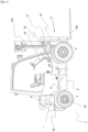
- the invention relates to a load handling machine 1 of the type, for example, of that shown in figures 1 And 2 .
- charge should be taken in a broad sense and equates a person with a charge.
- This handling machine 1 comprises a mobile chassis 2 equipped for this purpose with ground movement drive members 3.
- These ground movement drive members 3 may be formed by wheels, as illustrated in figures 1 And 2 , or, for example, by caterpillars.
- This machine 1 comprises, again for the movement of the chassis 2 and the operation of the load handling system 9 which will be described below, a motor 4 having a rotating motor shaft 5.
- This motor 4 can be a thermal engine or an electric motor.
- this motor is generally an electric motor/generator also called a reversible electric motor.
- the machine 1 comprises an energy accumulator 16 configured to supply electrical energy to the motor/generator, this energy accumulator 16 being formed of at least one or more batteries arranged on the chassis 2.
- the machine 1 comprises a mechanical 61 or hydraulic 62 transmission of the rotational movement of the engine shaft 5 to the drive members 3 for moving the machine 1 on the ground.
- the motor shaft 5 is coaxial with the motor 4.
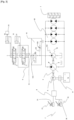
- the Figure 4 illustrates a mechanical transmission 61.
- This mechanical transmission 61 may be formed of one or more pinions or sets of pinions capable of meshing with each other. A portion of the pinions is carried by the input shaft of the mechanical transmission 61 which is engaged or formed by the motor shaft 5. At least one of the pinions is carried by an output shaft forming the drive shaft of the drive members 3 moving on the ground, such as the wheels of the machine.
- the machine 1 also comprises a load handling system 9.
- This load handling system 9 comprises at least one load handling device 10, at least one hydraulic actuator 11 for controlling the operation of the handling device 10, at least one hydraulic pump 12 equipped with a fluid outlet and a hydraulic circuit for connecting the hydraulic pump 12, in particular the fluid outlet of said hydraulic pump 12, to the at least one actuator 11.
- the load handling device 10 is said to be an arm device.
- This load handling device 10 comprises a lifting arm 102 mounted on the chassis 2 pivoting around a so-called horizontal axis for pivoting the arm 102 between a low position and a high position.
- This lifting arm 102 can carry a load handling accessory, such as a bucket, a nacelle or for example a fork.
- This hydraulic circuit 13 conventionally comprises one or more distributors making it possible to supply the actuators 11 from instructions provided by the control unit 8.
- the control unit 8 can itself control this or these distributors according to control instructions delivered for example via the actuation of a pivoting lever, also called a joystick, actuable by the operator and arranged at the driving position of the machine.
- the machine 1 comprises a system 15 for regulating the pressure and/or the flow rate of the hydraulic circuit 13 connecting the hydraulic pump 12 to at least one hydraulic actuator 11 for controlling the operation of the load handling device 10.
- This regulation system 15 may have a large number of forms.
- the system 15 for regulating the pressure and/or the flow rate of the hydraulic circuit 13 of the connection of the hydraulic pump 12 to the at least one actuator 11 comprises at least one pressure regulator 151 or a flow regulator 152 arranged on the hydraulic circuit 13 of connection of the hydraulic pump 12 to the at least one actuator 11, or on a branch 131 of diversion of said circuit 13.
- FIG. 4 illustrates a pressure regulator 151 in the form of a 2/2 valve arranged, upstream of the supply distributor of the hydraulic actuator 11 for controlling the operation of the handling device 10, between said distributor and the hydraulic pump 12 for supplying fluid to the hydraulic circuit 13 for connecting the hydraulic pump 12 to at least one actuator 11 for controlling the operation of the handling device 10.
- This 2/2 valve is movable between a closed position and an open position. In the closed position, this 2/2 valve here makes it possible to prevent the supply of fluid to the hydraulic actuator 11 for controlling the handling device 10 during operation.
- This 2/2 valve allows, by closing said circuit 13, an increase in the pressure of this circuit. This results, by increasing the pressure at the circuit 13, in the indirect creation of a braking torque on the motor shaft 5 which ensures the rotational drive of the hydraulic pump 12 for supplying fluid to the hydraulic circuit 13.
- This braking action can be modulated depending on the degree of closure of the valve.
- the hydraulic circuit 13 for connecting the hydraulic pump 12 to at least one hydraulic actuator 11 for controlling the operation of the handling device 10 also comprises, in the example shown in figures 3 And 4 , a branch 131 of the circuit 13, opening into a tank.
- This branch 131 can be equipped with a pressure regulator 151 and/or a flow regulator 152.
- bypass branch 131 can be omitted and the circuit 13 can also comprise only one main branch.
- a pressure regulator and/or a flow regulator can be envisaged in a form other than that described above, without departing from the scope of the invention.
- the hydraulic pump 12 of the load handling system 9 may be a variable displacement pump.
- the system 15 for regulating the pressure and/or the flow rate of the hydraulic circuit 13 connecting the hydraulic pump 12 to the at least one actuator 11 may comprise a control circuit 153 for the displacement of the hydraulic pump 12.
- an increase in the displacement of the hydraulic pump 12, coupled with the pressure control, may indirectly generate a braking action on the motor shaft 5 for rotating the hydraulic pump 12.
- the machine 1 also comprises a device 14 for determining the actual ground travel speed Vr of the machine.
- This device 14 is shown in the figures in the form of a sensor for the rotation speed of at least one of the ground drive members 3 of the machine, i.e. a sensor for the rotation speed of at least one wheel of the machine.
- the system 14 for determining the actual ground travel speed Vr of the machine could have integrated a geolocation system to provide location data to the control unit 8.
- the information from the sensor for the rotation speed of at least one of the ground drive members 3 of the machine relating to the actual ground travel speed Vr of the machine 1 is sent to the control unit 8.
- the control unit 8 is therefore configured to acquire data from the device 14 for determining the actual speed Vr of movement on the ground of the machine corresponding to said actual speed Vr.
- the engine 1 also includes, as mentioned above, a control unit 8 in the form of an electronic and computer system which includes for example a microprocessor and a working memory.
- the control unit may be in the form of a programmable automaton.
- the functions and steps described may be implemented in the form of a computer program or via hardware components (e.g. programmable gate arrays).
- control unit or its modules may be carried out by instruction sets or computer modules implemented in a processor or controller or may be carried out by dedicated electronic components or components of the programmable logic circuit type (or FPGA which is the acronym for field-programmable gate array, which literally corresponds to in-situ programmable gate array) or of the application-specific integrated circuit type (or ASIC which is the acronym for application-specific integrated circuit, which literally corresponds to application-specific integrated circuit). It is also possible to combine computer parts and electronic parts. Where it is specified that the unit or means or modules of said unit are configured to carry out a given operation, this means that the unit comprises computer instructions and the corresponding means of execution which make it possible to carry out said operation and/or that the unit comprises corresponding electronic components
- the machine 1 further comprises a control system 7 for the ground movement speed of the machine, and the control unit 8 is configured to acquire a signal from said control system 7, and to determine a ground movement speed Vc setpoint for the machine 1.
- the control system 7 for the ground travel speed of the machine 1 comprises a braking control member 71 mounted to move between two positions.
- This braking control member 71 is here in the form of a brake pedal.
- This control system 7 also comprises a member 73 for detecting an actuation of said braking control member 71.
- This detection member 73 is here in the form of a brake pedal position sensor.
- the data from said detection member 73 for an actuation of the braking control member 71 are sent to the control unit 8.
- This unit 8 The control system determines, from this information, the speed setpoint Vc for moving the machine on the ground.
- the senor provides information on the depression of the brake pedal and the control unit 8 determines, from this pedal depression value, the speed setpoint Vc, i.e. the ground speed of the machine expected after braking.
- the control unit 8 compares the speed setpoint values Vc and actual speed Vr.
- the control unit 8 is configured to control the regulation system 15 of the pressure and/or the flow rate of the hydraulic circuit 13 connecting the hydraulic pump 12 to the at least one actuator 11 in the direction of an increase in the pressure and/or an increase in the flow rate at the outlet of the hydraulic pump 12 at least when the ground travel speed setpoint Vc is lower than the actual ground travel speed Vr of the machine determined by the device 14 for determining the actual ground travel speed of the machine 1.
- the control unit 8 does not act on the regulation system 15 of the pressure and/or the flow rate of the hydraulic circuit 13 connecting the hydraulic pump 12 to at least one actuator 11 for controlling the operation of the handling device 10.
- the control unit 8 compensates for insufficient braking by acting on the pressure and/or flow regulation system 15 of the hydraulic circuit 13 to increase the pressure in said circuit 13 and thus generate mechanical resistance inducing, indirectly, a braking torque on the motor shaft 5 of the rotational drive of the hydraulic pump 12 to supplement the braking action controlled via the braking control member 71.
- a similar operation can be obtained with an acceleration control member 72 and a member 74 for detecting an actuation of said acceleration control member 72.
- the acceleration control member 72 is an accelerator pedal
- the member 74 for detecting an actuation said acceleration control member 72 may be a sensor for detecting the position of said accelerator pedal.
- the data from the detection member 74 of an actuation of the acceleration control member 72 are sent to the control unit 8.
- the control unit 8 determines, from this information, the speed setpoint Vc for movement on the ground of the machine.
- the senor here provides information on the release of the accelerator pedal and the control unit 8, from this value of release of the accelerator pedal, determines the speed setpoint Vc, i.e. the ground speed of the machine expected after the deceleration of the machine1.
- the control unit 8 compares the speed setpoint values Vc and actual speed Vr and acts on the system 15 for regulating the pressure and/or flow rate of the hydraulic circuit 13, in a similar manner to what was described above in the case of actuation of the braking control member.
- the braking control member 71 can take the form of a speed variator or a speed limiter 75. The same applies to the acceleration control member 72.
- control unit 8 can, in addition, be configured to control the regulation system 15 of the pressure and/or the flow rate of the hydraulic circuit 13 connecting the hydraulic pump 12 to the at least one actuator 11, as a function of the charge level of the energy accumulator 16.
- a braking action can be obtained by acting on the regulation system 15 of the pressure and/or the flow rate of the hydraulic circuit 13 by increasing the pressure the flow rate in said hydraulic circuit 13, as described above, or even by increasing the displacement of the hydraulic pump 12.
- control unit 8 makes it possible to use a part of the handling device 10 and in particular the fluid circuit of the handling device 10, as an emergency brake for the machine 1.
- This emergency braking action can be modulated according to the action on the pressure and/or flow regulation system 15.
Landscapes
- Engineering & Computer Science (AREA)
- Transportation (AREA)
- Structural Engineering (AREA)
- Civil Engineering (AREA)
- Life Sciences & Earth Sciences (AREA)
- Geology (AREA)
- Mechanical Engineering (AREA)
- Fluid-Pressure Circuits (AREA)
- Forklifts And Lifting Vehicles (AREA)
- Control Of Fluid Gearings (AREA)
- Operation Control Of Excavators (AREA)
Claims (11)
- Lasthandhabungsmaschine (1), umfassend einen Rahmen (2), der mit Antriebsorganen (3) zur Fortbewegung am Boden ausgestattet ist, einen Motor (4), der eine drehende Antriebswelle (5) aufweist, eine mechanische (61) oder hydraulische (62) Übertragung der Drehbewegung der Antriebswelle (5) des Motors (4) auf die Antriebsorgane (3) zur Fortbewegung am Boden, ein Steuersystem (7) zur Steuerung der Fortbewegungsgeschwindigkeit der Maschine (1) am Boden, eine Ansteuerungseinheit (8), die mindestens dazu ausgestaltet ist, ein Signal des Steuersystems (7) zu erfassen und einen Geschwindigkeitssollwert (Vc) für die Fortbewegung am Boden zu bestimmen, ein Lasthandhabungssystem (9), umfassend mindestens eine Lasthandhabungsvorrichtung (10), mindestens einen hydraulischen Aktor (11) zur Steuerung der Handhabungsvorrichtung (10) im Betrieb, mindestens eine Hydraulikpumpe (12), die mit einem Fluidauslass ausgestattet ist, und einen Hydraulikkreislauf (13) zum Verbinden der Hydraulikpumpe (12) mit dem mindestens einen Aktor (11), eine Vorrichtung (14) zur Bestimmung der Ist-Geschwindigkeit (Vr) der Fortbewegung der Maschine am Boden, wobei die Hydraulikpumpe (12) des Lasthandhabungssystems (9), für ihren Betrieb, mit der Antriebswelle (5) des Motors (4) gekoppelt ist, der einen Allzweckmotor (4) zur Steuerung des Antriebs zur Fortbewegung am Boden der Antriebsorgane (3) zur Fortbewegung am Boden und des Lasthandhabungssystems (9) bildet, wobei die Maschine (1) mit mindestens einem Regelungssystem (15) zur Regelung des Drucks und/oder des Volumenstroms des Hydraulikkreislaufs (13) zum Verbinden der Hydraulikpumpe (12) mit dem mindestens einen hydraulischen Aktor (11) zur Steuerung der Handhabungsvorrichtung (10) im Betrieb ausgestattet ist, dadurch gekennzeichnet, dass die Ansteuerungseinheit (8) dazu ausgestaltet ist, das Regelungssystem (15) zur Regelung des Drucks und/oder des Volumenstroms des Hydraulikkreislaufs (13) zum Verbinden der Hydraulikpumpe (12) mit dem mindestens einen Aktor (11) in Abhängigkeit mindestens von dem Ergebnis des Vergleichs zwischen dem Geschwindigkeitssollwert (Vc) für die Fortbewegung am Boden und der Ist-Geschwindigkeit (Vr) der Fortbewegung der Maschine (1) am Boden, die von der Vorrichtung (14) zur Bestimmung der Ist-Geschwindigkeit der Fortbewegung der Maschine (1) am Boden bestimmt wird, zu steuern.
- Lasthandhabungsmaschine (1) nach Anspruch 1, dadurch gekennzeichnet, dass die Ansteuerungseinheit (8) dazu ausgestaltet ist, das Regelungssystem (15) zur Regelung des Drucks und/oder des Volumenstroms des Hydraulikkreislaufs (13) zum Verbinden der Hydraulikpumpe (12) mit dem mindestens einen Aktor (11) im Sinne einer Erhöhung des Drucks und/oder einer Erhöhung des Volumenstroms an dem Auslass der Hydraulikpumpe (12) mindestens zu steuern, wenn der Geschwindigkeitssollwert (Vc) für die Fortbewegung am Boden geringer als die Ist-Geschwindigkeit (Vr) der Fortbewegung der Maschine (1) am Boden ist, die von der Vorrichtung (14) zur Bestimmung der Ist-Geschwindigkeit der Fortbewegung der Maschine (1) am Boden bestimmt wird.
- Lasthandhabungsmaschine (1) nach einem der Ansprüche 1 oder 2, dadurch gekennzeichnet, dass der Motor (4) ein elektrischer Motor/Generator, auch reversierbarer Elektromotor genannt, ist, dass die Maschine (1) einen Energieakkumulator (16), der dazu ausgestaltet ist, den Motor/Generator in einer ersten sogenannten Motor-Betriebsart des Motors/Generators mit elektrischer Energie zu versorgen und in einer zweiten sogenannten Generator-Betriebsart des Motors/Generators eine elektrische Energie vom Motor/Generator zu empfangen und zu speichern, und ein System (17) zur Bestimmung eines Parameters, der für den Ladestand des Energieakkumulators (16) repräsentativ ist, umfasst, und dadurch, dass die Ansteuerungseinheit (8) dazu ausgestaltet ist, das Regelungssystem (15) zur Regelung des Drucks und/oder des Volumenstroms des Hydraulikkreislaufs (13) zum Verbinden der Hydraulikpumpe (12) mit dem mindestens einen Aktor (11) in Abhängigkeit von dem Ladestand des Energieakkumulators (16) zu steuern.
- Lasthandhabungsmaschine (1) nach Anspruch 3, dadurch gekennzeichnet, dass der Energieakkumulator (16) mindestens eine Batterie umfasst und dass das System (17) zur Bestimmung eines Parameters, der für den Ladestand des Energieakkumulators (16) repräsentativ ist, ein Sensor zum Messen der Spannung der Batterie oder Batterien ist.
- Lasthandhabungsmaschine (1) nach einem der Ansprüche 1 bis 4, dadurch gekennzeichnet, dass das Steuersystem (7) zur Steuerung der Fortbewegungsgeschwindigkeit der Maschine am Boden ein Bremssteuerorgan (71), das zwischen mindestens zwei Stellungen beweglich montiert ist, und/oder ein Beschleunigungssteuerorgan (72), das zwischen mindestens zwei Stellungen beweglich montiert ist, und mindestens ein Detektionsorgan (73) zur Detektion einer Betätigung des Bremssteuerorgans (71) und/oder mindestens ein Detektionsorgan (74) zur Detektion einer Betätigung des Beschleunigungssteuerorgans (72) umfasst.
- Lasthandhabungsmaschine (1) nach Anspruch 5, dadurch gekennzeichnet, dass die Ansteuerungseinheit (8) dazu ausgestaltet ist, das Regelungssystem (15) zur Regelung des Drucks und/oder des Volumenstroms des Hydraulikkreislaufs (13) zum Verbinden der Hydraulikpumpe (12) mit dem mindestens einen Aktor (11) in Abhängigkeit mindestens von dem Ergebnis des Vergleichs zwischen dem Geschwindigkeitssollwert (Vc) für die Fortbewegung am Boden, der mindestens in Abhängigkeit von den Daten bestimmt wird, die von dem oder einem der Detektionsorgane (73) zur Detektion einer Betätigung des Bremssteuerorgans (71) und/oder dem oder einem der Detektionsorgane (74) zur Detektion einer Betätigung des Beschleunigungssteuerorgans (72) bereitgestellt werden, und der Ist-Geschwindigkeit (Vr) der Fortbewegung der Maschine (1) am Boden, die von der Vorrichtung (14) zur Bestimmung der Ist-Geschwindigkeit der Fortbewegung der Maschine am Boden bestimmt wird, zu steuern.
- Lasthandhabungsmaschine (1) nach einem der Ansprüche 1 bis 6, dadurch gekennzeichnet, dass das Regelungssystem (15) zur Regelung des Drucks und/oder des Volumenstroms des Hydraulikkreislaufs (13) zum Verbinden der Hydraulikpumpe (12) mit dem mindestens einen Aktor (11) mindestens einen Druckregler (151) oder einen Volumenstromregler (152) umfasst, der an dem Hydraulikkreislauf (13) zum Verbinden der Hydraulikpumpe (12) mit dem mindestens einen Aktor (11) oder an einer Abzweigleitung (131) des Kreislaufs (13) angeordnet ist.
- Lasthandhabungsmaschine (1) nach einem der Ansprüche 1 bis 7, dadurch gekennzeichnet, dass die Hydraulikpumpe (12) des Lasthandhabungssystems (9) eine Pumpe mit variablem Hubraum ist und dass das Regelungssystem (15) zur Regelung des Drucks und/oder des Volumenstroms des Hydraulikkreislaufs (13) zum Verbinden der Hydraulikpumpe (12) mit dem mindestens einen Aktor (11) einen Steuerkreis (153) zur Steuerung des Hubraums der Hydraulikpumpe (12) umfasst.
- Lasthandhabungsmaschine (1) nach einem der Ansprüche 1 bis 8, dadurch gekennzeichnet, dass die an dem Rahmen (2) montierte Lasthandhabungsvorrichtung (10) mindestens einen Hubmast (101) oder einen Hubarm (102) und ein Lasthandhabungszubehörteil (103), das von dem Mast (101) oder dem Arm (102) getragen wird, umfasst.
- Lasthandhabungsmaschine (1) nach einem der Ansprüche 1 bis 9, dadurch gekennzeichnet, dass der oder mindestens einer der hydraulischen Aktoren (11) zur Steuerung der Handhabungsvorrichtung (10) im Betrieb ein Zylinder ist.
- Lasthandhabungsmaschine nach einem der Ansprüche 1 oder 2, dadurch gekennzeichnet, dass die Vorrichtung (14) zur Bestimmung der Ist-Geschwindigkeit (Vr) der Fortbewegung der Maschine (1) am Boden mindestens einen Sensor für die Drehzahl mindestens eines der Antriebsorgane (3) am Boden der Maschine und/oder ein Geolokalisierungssystem umfasst.
Applications Claiming Priority (1)
| Application Number | Priority Date | Filing Date | Title |
|---|---|---|---|
| FR2214414A FR3144125B1 (fr) | 2022-12-23 | 2022-12-23 | Engin de manutention de charge |
Publications (3)
| Publication Number | Publication Date |
|---|---|
| EP4389683A1 EP4389683A1 (de) | 2024-06-26 |
| EP4389683B1 true EP4389683B1 (de) | 2025-06-25 |
| EP4389683C0 EP4389683C0 (de) | 2025-06-25 |
Family
ID=85791990
Family Applications (1)
| Application Number | Title | Priority Date | Filing Date |
|---|---|---|---|
| EP23217496.1A Active EP4389683B1 (de) | 2022-12-23 | 2023-12-18 | Lasthandhabungsmaschine |
Country Status (2)
| Country | Link |
|---|---|
| EP (1) | EP4389683B1 (de) |
| FR (1) | FR3144125B1 (de) |
Citations (1)
| Publication number | Priority date | Publication date | Assignee | Title |
|---|---|---|---|---|
| EP2993332B1 (de) * | 2013-12-17 | 2021-11-03 | Komatsu Ltd. | Nutzfahrzeug und verfahren zur steuerung davon |
Family Cites Families (3)
| Publication number | Priority date | Publication date | Assignee | Title |
|---|---|---|---|---|
| US6782961B1 (en) * | 1999-10-18 | 2004-08-31 | Kabushiki Kaisha Toyoda Jidoshokki Seisakusho | Driving control apparatus for industrial vehicle |
| DE19955311C2 (de) * | 1999-11-17 | 2003-12-24 | Jungheinrich Ag | Antriebssystem für ein Flurförderzeug |
| DE102007019506A1 (de) * | 2007-04-25 | 2008-10-30 | Jungheinrich Ag | Verfahren und Vorrichtung zur Kippvermeidung eines Gegengewichtsstaplers |
-
2022
- 2022-12-23 FR FR2214414A patent/FR3144125B1/fr active Active
-
2023
- 2023-12-18 EP EP23217496.1A patent/EP4389683B1/de active Active
Patent Citations (1)
| Publication number | Priority date | Publication date | Assignee | Title |
|---|---|---|---|---|
| EP2993332B1 (de) * | 2013-12-17 | 2021-11-03 | Komatsu Ltd. | Nutzfahrzeug und verfahren zur steuerung davon |
Also Published As
| Publication number | Publication date |
|---|---|
| FR3144125A1 (fr) | 2024-06-28 |
| EP4389683A1 (de) | 2024-06-26 |
| EP4389683C0 (de) | 2025-06-25 |
| FR3144125B1 (fr) | 2025-04-04 |
Similar Documents
| Publication | Publication Date | Title |
|---|---|---|
| EP4408786B1 (de) | Handhabungsmaschine | |
| EP4183609B1 (de) | Elektrisch angetriebenes hydrostatisches nutzfahrzeug mit hydraulischer unterstützung beim antrieb | |
| EP4389683B1 (de) | Lasthandhabungsmaschine | |
| EP4129727B1 (de) | Lastenfördergerät | |
| FR2865256A1 (fr) | Regulateur pour vehicule equipe d'une boite de vitesses hydrostatique | |
| WO2023041875A1 (fr) | Dispositif et procede pour le pilotage en traction d'un circuit d'assistance hydraulique | |
| EP3976891B1 (de) | Lasthandhabungsfahrzeug | |
| EP4453449A1 (de) | Vorrichtung und verfahren zur steuerung eines elektrohydraulischen getriebes | |
| EP3003757B1 (de) | Verfahren und vorrichtung zum steuerung/kommandieren eines differenziellen hydraulikmoduls für ein hybridfahrzeug | |
| WO2023094743A1 (fr) | Engin automoteur, notamment un engin automoteur de manutention de charge | |
| EP4389687B1 (de) | Elektrisches arbeitsfahrzeug mit hydrostatischem antriebsstrang | |
| EP4308830B1 (de) | System und verfahren zur verbesserten traktionssteuerung | |
| EP4041667B1 (de) | Lastförderfahrzeug mit wärmekraftmaschine und verfahren zur regelung der drehzahl des verbrennungsmotors eines solchen fahrzeugs | |
| FR3156438A3 (fr) | Machine de manutention comprenant un vérin hydraulique et procédé de commande correspondant | |
| EP2607646A1 (de) | Aktuator zur Motorsteuerung mit Schubkurbelmechanismus | |
| EP3225435A1 (de) | Schienenfahrzeug mit regulierbarem hydrostatischen bremssystem | |
| WO2023118754A1 (fr) | Procede de mise en service ou de desengagement ameliore pour une transmission electrohydraulique | |
| WO2024156751A1 (fr) | Machine de levage | |
| EP4686695A1 (de) | Handhabungsmaschine mit einem magnetventilsystem zur steuerung einer hydraulischen betätigungsvorrichtung eines maschinenorgans | |
| FR3083536A1 (fr) | Dispositif de levage comprenant un circuit hydraulique perfectionne pour autoriser une phase de retour bennage rapide | |
| EP4507920A1 (de) | Verfahren zur steuerung einer brennstoffzelle einer arbeitsmaschine | |
| EP3003763B1 (de) | Verfahren und vorrichtung zur steuerung eines hydraulikmoduls für ein hybridfahrzeug | |
| WO2023232449A1 (fr) | Système d'entraînement pour une machine de travail mobile | |
| WO2025078777A1 (fr) | Dispositif et procede de commande de couple de machine hydraulique | |
| FR3058101A1 (fr) | Systeme d'assistance a l'entrainement d'un vehicule tout terrain |
Legal Events
| Date | Code | Title | Description |
|---|---|---|---|
| PUAI | Public reference made under article 153(3) epc to a published international application that has entered the european phase |
Free format text: ORIGINAL CODE: 0009012 |
|
| STAA | Information on the status of an ep patent application or granted ep patent |
Free format text: STATUS: THE APPLICATION HAS BEEN PUBLISHED |
|
| AK | Designated contracting states |
Kind code of ref document: A1 Designated state(s): AL AT BE BG CH CY CZ DE DK EE ES FI FR GB GR HR HU IE IS IT LI LT LU LV MC ME MK MT NL NO PL PT RO RS SE SI SK SM TR |
|
| STAA | Information on the status of an ep patent application or granted ep patent |
Free format text: STATUS: REQUEST FOR EXAMINATION WAS MADE |
|
| 17P | Request for examination filed |
Effective date: 20241216 |
|
| RIC1 | Information provided on ipc code assigned before grant |
Ipc: B66F 9/075 20060101AFI20250129BHEP |
|
| GRAP | Despatch of communication of intention to grant a patent |
Free format text: ORIGINAL CODE: EPIDOSNIGR1 |
|
| STAA | Information on the status of an ep patent application or granted ep patent |
Free format text: STATUS: GRANT OF PATENT IS INTENDED |
|
| INTG | Intention to grant announced |
Effective date: 20250313 |
|
| GRAS | Grant fee paid |
Free format text: ORIGINAL CODE: EPIDOSNIGR3 |
|
| GRAA | (expected) grant |
Free format text: ORIGINAL CODE: 0009210 |
|
| STAA | Information on the status of an ep patent application or granted ep patent |
Free format text: STATUS: THE PATENT HAS BEEN GRANTED |
|
| AK | Designated contracting states |
Kind code of ref document: B1 Designated state(s): AL AT BE BG CH CY CZ DE DK EE ES FI FR GB GR HR HU IE IS IT LI LT LU LV MC ME MK MT NL NO PL PT RO RS SE SI SK SM TR |
|
| REG | Reference to a national code |
Ref country code: GB Ref legal event code: FG4D Free format text: NOT ENGLISH |
|
| REG | Reference to a national code |
Ref country code: CH Ref legal event code: EP |
|
| REG | Reference to a national code |
Ref country code: CH Ref legal event code: EP |
|
| REG | Reference to a national code |
Ref country code: IE Ref legal event code: FG4D Free format text: LANGUAGE OF EP DOCUMENT: FRENCH |
|
| REG | Reference to a national code |
Ref country code: DE Ref legal event code: R096 Ref document number: 602023004322 Country of ref document: DE |
|
| U01 | Request for unitary effect filed |
Effective date: 20250715 |
|
| U07 | Unitary effect registered |
Designated state(s): AT BE BG DE DK EE FI FR IT LT LU LV MT NL PT RO SE SI Effective date: 20250721 |
|
| PG25 | Lapsed in a contracting state [announced via postgrant information from national office to epo] |
Ref country code: NO Free format text: LAPSE BECAUSE OF FAILURE TO SUBMIT A TRANSLATION OF THE DESCRIPTION OR TO PAY THE FEE WITHIN THE PRESCRIBED TIME-LIMIT Effective date: 20250925 Ref country code: GR Free format text: LAPSE BECAUSE OF FAILURE TO SUBMIT A TRANSLATION OF THE DESCRIPTION OR TO PAY THE FEE WITHIN THE PRESCRIBED TIME-LIMIT Effective date: 20250926 |
|
| PG25 | Lapsed in a contracting state [announced via postgrant information from national office to epo] |
Ref country code: HR Free format text: LAPSE BECAUSE OF FAILURE TO SUBMIT A TRANSLATION OF THE DESCRIPTION OR TO PAY THE FEE WITHIN THE PRESCRIBED TIME-LIMIT Effective date: 20250625 |
|
| PG25 | Lapsed in a contracting state [announced via postgrant information from national office to epo] |
Ref country code: RS Free format text: LAPSE BECAUSE OF FAILURE TO SUBMIT A TRANSLATION OF THE DESCRIPTION OR TO PAY THE FEE WITHIN THE PRESCRIBED TIME-LIMIT Effective date: 20250925 |
|
| PG25 | Lapsed in a contracting state [announced via postgrant information from national office to epo] |
Ref country code: IS Free format text: LAPSE BECAUSE OF FAILURE TO SUBMIT A TRANSLATION OF THE DESCRIPTION OR TO PAY THE FEE WITHIN THE PRESCRIBED TIME-LIMIT Effective date: 20251025 |
|
| PG25 | Lapsed in a contracting state [announced via postgrant information from national office to epo] |
Ref country code: SM Free format text: LAPSE BECAUSE OF FAILURE TO SUBMIT A TRANSLATION OF THE DESCRIPTION OR TO PAY THE FEE WITHIN THE PRESCRIBED TIME-LIMIT Effective date: 20250625 |
|
| PG25 | Lapsed in a contracting state [announced via postgrant information from national office to epo] |
Ref country code: CZ Free format text: LAPSE BECAUSE OF FAILURE TO SUBMIT A TRANSLATION OF THE DESCRIPTION OR TO PAY THE FEE WITHIN THE PRESCRIBED TIME-LIMIT Effective date: 20250625 |
|
| PGFP | Annual fee paid to national office [announced via postgrant information from national office to epo] |
Ref country code: IE Payment date: 20251219 Year of fee payment: 3 |
|
| PG25 | Lapsed in a contracting state [announced via postgrant information from national office to epo] |
Ref country code: PL Free format text: LAPSE BECAUSE OF FAILURE TO SUBMIT A TRANSLATION OF THE DESCRIPTION OR TO PAY THE FEE WITHIN THE PRESCRIBED TIME-LIMIT Effective date: 20250625 |
|
| PG25 | Lapsed in a contracting state [announced via postgrant information from national office to epo] |
Ref country code: SK Free format text: LAPSE BECAUSE OF FAILURE TO SUBMIT A TRANSLATION OF THE DESCRIPTION OR TO PAY THE FEE WITHIN THE PRESCRIBED TIME-LIMIT Effective date: 20250625 |
|
| PG25 | Lapsed in a contracting state [announced via postgrant information from national office to epo] |
Ref country code: ES Free format text: LAPSE BECAUSE OF FAILURE TO SUBMIT A TRANSLATION OF THE DESCRIPTION OR TO PAY THE FEE WITHIN THE PRESCRIBED TIME-LIMIT Effective date: 20250625 |
|
| U20 | Renewal fee for the european patent with unitary effect paid |
Year of fee payment: 3 Effective date: 20251230 |
|
| PLBE | No opposition filed within time limit |
Free format text: ORIGINAL CODE: 0009261 |
|
| STAA | Information on the status of an ep patent application or granted ep patent |
Free format text: STATUS: NO OPPOSITION FILED WITHIN TIME LIMIT |