EP4389687B1 - Elektrisches arbeitsfahrzeug mit hydrostatischem antriebsstrang - Google Patents
Elektrisches arbeitsfahrzeug mit hydrostatischem antriebsstrang Download PDFInfo
- Publication number
- EP4389687B1 EP4389687B1 EP23217906.9A EP23217906A EP4389687B1 EP 4389687 B1 EP4389687 B1 EP 4389687B1 EP 23217906 A EP23217906 A EP 23217906A EP 4389687 B1 EP4389687 B1 EP 4389687B1
- Authority
- EP
- European Patent Office
- Prior art keywords
- displacement
- drive
- hydrostatic
- motor
- drive unit
- Prior art date
- Legal status (The legal status is an assumption and is not a legal conclusion. Google has not performed a legal analysis and makes no representation as to the accuracy of the status listed.)
- Active
Links
Images



Classifications
-
- B—PERFORMING OPERATIONS; TRANSPORTING
- B66—HOISTING; LIFTING; HAULING
- B66F—HOISTING, LIFTING, HAULING OR PUSHING, NOT OTHERWISE PROVIDED FOR, e.g. DEVICES WHICH APPLY A LIFTING OR PUSHING FORCE DIRECTLY TO THE SURFACE OF A LOAD
- B66F9/00—Devices for lifting or lowering bulky or heavy goods for loading or unloading purposes
- B66F9/06—Devices for lifting or lowering bulky or heavy goods for loading or unloading purposes movable, with their loads, on wheels or the like, e.g. fork-lift trucks
- B66F9/075—Constructional features or details
- B66F9/20—Means for actuating or controlling masts, platforms, or forks
Definitions
- the invention relates to an electric work vehicle driven in movement by a hydrostatic transmission drive train, also called a hydrostatic drive train.
- Work vehicles are generally equipped with a powertrain comprising a diesel-type internal combustion engine coupled to a hydrostatic transmission.
- a hydrostatic transmission may in particular comprise a continuously variable displacement hydrostatic pump and one or more fixed displacement hydrostatic motors.
- a hydrostatic driveline is capable of developing significant tractive effort in a four-wheel drive configuration, and of enabling the work vehicle to achieve high forward speeds in a two-wheel drive configuration.
- switching from a four-wheel drive configuration to a two-wheel drive configuration, and vice versa cannot be carried out while the work vehicle is moving. Indeed, switching from one configuration to the other generates a sudden variation in the flow rate of hydraulic fluid which cannot be controlled either by a variation in the displacement of the hydrostatic pump, or by a variation in the speed of the internal combustion engine, the responsiveness of the hydrostatic pump and the internal combustion engine not being sufficient. Switching between the four-wheel drive and two-wheel drive configurations is therefore carried out when the work vehicle is stationary.
- An idea underlying the invention is to provide a work vehicle equipped with a hydrostatic drive train of simple arrangement, capable of developing a significant tractive effort while allowing the work vehicle to reach high forward speeds.
- the particularly responsive electric motor speed control makes it possible to control the variation in hydraulic fluid flow resulting from the variation in the total engine displacement when switching the drive displacement.
- the work vehicle can thus switch smoothly and on the move between hydrostatic configurations developing significant traction forces. traction but low forward speeds, and hydrostatic configurations with lower total engine displacement, developing little tractive effort but allowing high forward speeds to be achieved.
- the hydrostatic pump is an axial piston volumetric pump or a radial piston volumetric pump.
- the hydrostatic pump has a fixed displacement.
- the hydrostatic pump has a continuously variable displacement.
- the hydrostatic motors are axial piston motors or radial piston motors.
- the work vehicle further comprises a forward speed sensor configured to measure a forward speed of the work vehicle, and the control unit is configured to control the switching device so as to switch the driving displacement to change from slow travel drive to fast travel drive when the travel speed is greater than or equal to a switching speed, and fast moving drive to slow moving drive when the moving speed is lower than the switching speed.
- the control unit thus automatically controls the switching of the engine displacement in order to optimize the performance of the hydrostatic drive train of the work vehicle.
- control unit comprises a memory and the switching speed has been previously determined by digital simulation or by workshop testing and stored in the memory of said control unit.
- the work vehicle further comprises a travel requirement sensor configured to measure a travel requirement, and the switching speed is a function of the forward speed of the work vehicle and the travel requirement.
- the switching device comprises a switching control allowing an operator to manually switch the driving displacement.
- the two drive units comprise a front drive unit comprising two front drive wheels and at least one front hydrostatic motor, and a drive unit comprising two rear drive wheels and at least one rear hydrostatic motor, the front and rear hydrostatic motors being connected to each other in parallel.
- At least one of the front drive unit and the rear drive unit comprises a transmission axle equipped with a pair of drive wheels and a hydrostatic motor coupled to the two drive wheels.
- the switching device comprises a set of valves configured to selectively allow the supply of hydraulic fluid to a said variable drive unit by the hydrostatic pump for the displacement drive and to prevent the supply of hydraulic fluid to said variable drive unit by the hydrostatic pump for the rapid displacement drive.
- the valve assembly prevents the supply of hydraulic fluid to said variable drive unit
- no hydrostatic motor of the variable drive unit is supplied with hydraulic fluid by the hydrostatic pump.
- the driving displacement that the variable drive unit functionally contributes to the total engine displacement is zero, even though the displacement of the hydrostatic motor(s) not supplied with hydraulic fluid would not be physically zero.
- the driving displacement that the variable drive unit functionally contributes to the total engine displacement is variable at least due to the valve assembly; it may even be variable only due to the valve assembly, if the or each hydrostatic motor of the variable drive unit is of constant displacement.
- one of the rear drive unit and the front drive unit is configured as a variable drive unit, and wherein the slow travel drive is four-wheel drive, front and rear, and the fast travel drive is two-wheel drive, front or rear.
- said or each hydrostatic motor of a variable drive unit is of constant displacement.
- a said variable drive unit comprises a dual-displacement hydrostatic motor
- the switching device is configured to selectively switch the dual-displacement hydrostatic motor into a first displacement for fast travel drive and into a second displacement strictly greater than the first displacement for slow travel drive.
- the engine displacement that the variable drive unit functionally contributes to the total engine displacement is variable at least due to the switching of the dual-displacement hydrostatic motor between the first displacement and the second displacement, i.e. due to the physical change in the displacement of the dual-displacement hydrostatic motor.
- the dual-displacement hydrostatic motor does not have a continuously variable displacement.
- This vehicle may be an all-terrain or off-road electric powered truck, such as an electric vertical mast forklift, an electric articulated chassis forklift, an electric load handling truck, for example with a telescopic arm, a rotating telescopic forklift or an electric compact loader.
- an electric work vehicle may be an all-terrain or off-road electric powered truck, such as an electric vertical mast forklift, an electric articulated chassis forklift, an electric load handling truck, for example with a telescopic arm, a rotating telescopic forklift or an electric compact loader. This list is not exhaustive.
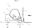
- the work vehicle 1 is an electric forklift with a vertical mast.
- a vehicle comprises a chassis 2 topped with a driver's cab 3 inside which an operator can sit.
- the chassis 2 is equipped with a ground engagement structure S comprising two driving axles, front 7F and rear 7R, located one after the other in the direction of travel D of the work vehicle 1.
- the front driving axle 7F and the rear driving axle 7R each comprise two driving wheels, denoted 8F and 8R respectively.
- the driving while moving the work vehicle is enabled by the rotation of the driving wheels 8F and/or 8R in contact with the ground S.
- the work vehicle 1 also comprises a lifting mast 4 articulated at the front of the chassis 2.
- the lifting mast 4 is generally equipped with forks 5 mounted so as to move up and down along the lifting mast 4.
- the lifting mast 4 is coupled to the chassis 2 by a first pivot connection P with a horizontal pivot axis extending transversely to the direction of movement D of the work vehicle, parallel to the axis of rotation of the drive wheels 8F, 8R.
- At least one actuator 6, such as a hydraulic cylinder, arranged between the chassis 2 and the lifting mast 4 enables the lifting mast 4 to be driven to pivot about the pivot axis P in the direction of an inclination of the lifting mast 4 towards the front or rear of the chassis 2.
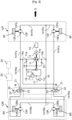
- the work vehicle 1 is equipped with a hydrostatic drive train comprising an electric motor 9 supplied with electrical energy by an electrical energy source 10, a hydrostatic pump 11 driven in rotation by the motor electric 9, and two drive units, namely a front drive unit 12F equipped with the two front drive wheels 8F and a rear drive unit 12R equipped with the two rear drive wheels 8R.
- the electrical energy source 10 may consist of a modular assembly of electrochemical accumulator batteries and/or energy storage capacitors.
- the output shaft of the electric motor 9 is coupled to the drive shaft of the hydrostatic pump 11, for example by means of a keyed or splined connection system.
- the electric motor 9 is dedicated solely to the rotational drive of the hydrostatic pump 11, with the exception of a booster pump 15 which supplies hydraulic fluid to a booster circuit described later.
- the rotational speed of the electric motor 9 can thus be accelerated or slowed down to vary only the flow rate of hydraulic fluid delivered by the hydrostatic pump 11.
- the hydrostatic pump 11 has a continuously variable displacement D p , for example controlled hydraulically, hydromechanically or electrically.
- the hydrostatic pump has a fixed displacement.
- the hydrostatic pump 11 is a volumetric pump with pistons, axial (barrel or straight axis pump, or connecting rod or broken axis pump) or radial.
- the displacement of the hydrostatic pump 11 is for example controlled by a displacement regulating device (not shown) configured to control the displacement as a function of the rotation speed of the electric motor 9.
- a displacement regulating device (not shown) configured to control the displacement as a function of the rotation speed of the electric motor 9.
- Such regulation of the displacement of the hydrostatic pump 11 as a function of the engine speed is said to be of the “automotive” type; it can be carried out by hydraulic or electrohydraulic control of the displacement, preferably proportional.
- the hydrostatic pump 11 is provided with a discharge port 11a and a suction port 11b.
- Each drive unit, front 12F and rear 12R respectively further comprises a hydrostatic motor, front 13F and rear 13R respectively.
- the hydrostatic motor front 13F, rear 13R respectively, enables the rotational drive of a front 8F, rear 8R respectively drive wheel.
- the 13F front hydrostatic motors are fixed displacement D m (f) and the 13R rear hydrostatic motors are fixed displacement D m (r) .
- the front 13F and rear 13R hydrostatic motors are axial piston motors (barrel or straight axis motors) or radial piston motors.
- the hydrostatic pump 11 and the front 13F and rear 13R hydrostatic motors operate in a closed circuit.
- the hydraulic fluid is first delivered by the hydrostatic pump 11 to the front 13F and rear 13R hydrostatic motors via high-pressure fluid connections in the hydraulic circuitry of the hydrostatic drive train.
- the hydraulic fluid is then returned to the suction side of the hydrostatic pump 11 via low-pressure fluid connections.
- the hydraulic fluid is a mineral or synthetic oil obtained by refining petroleum.
- the hydraulic circuitry of the hydrostatic drive train comprises a high-pressure main line 14a and a low-pressure main line 14b.
- the high-pressure main line 14a branches into four high-pressure branches 141Fa, 141Ra.
- the high-pressure main line 14a and the two high-pressure branches 141Fa, respectively 141Ra connect the discharge port 11a of the hydrostatic pump 11 to the inlet ports 13Fa, respectively 13Ra, of the front hydrostatic motors 13F, respectively rear 13R.
- the low-pressure main line 14b also branches into four low-pressure branches 141Fb, 141Rb.
- the two low-pressure branches 141Fb, respectively 141Rb, and the low-pressure main line 14b connect the outlet ports 13Fb, respectively 13Rb, of the front hydrostatic motors 13F, respectively rear 13R to the suction port 11b of the hydrostatic pump 11.
- each of the front hydrostatic motors 13F and rear 13R is connected in parallel to the hydrostatic pump 11.
- the main pipes 14a, 14b and their branches 141Fa, 141Ra, 141Fb, 141Rb are, for example, steel pipes or flexible pipelines.
- the hydrostatic drive train further comprises, in a manner known per se, a booster pump 15 coupled to the hydrostatic pump 11 and, therefore, driven by the electric motor 9.
- the booster pump 15 draws hydraulic fluid from a reservoir 16 through a strainer 17 and delivers it, via booster valves 18, into one of the low-pressure fluid connections 14b, 141Fb or 141Rb to compensate internal leaks in the closed hydraulic circuit of the hydrostatic drive train.
- the supply pressure of the booster circuit is limited by pressure limiter 19.
- the work vehicle 1 further comprises a switching device 20.
- the switching device 20 comprises two on-off, two-position, three-way controlled solenoid valves 21, each controlled by a solenoid 23.
- Such solenoid valves comprise a fixed, hollow body within which a movable slide valve moves. Orifices drilled in the body make it possible to establish the desired connections or closures between the different ways to control the flow of the hydraulic fluid.
- the solenoid valves 21 are positioned on the high pressure branches 141Ra, i.e. between the discharge port 11a of the hydrostatic pump 11 and the inlet ports 13Ra of the rear hydrostatic motors 13R.
- Each solenoid valve 21 has a first position I, illustrated in the Figure 2 , allowing the flow of hydraulic fluid between the hydrostatic pump 11 and the rear hydrostatic motors 13R.
- the first position I corresponds, for example, to the position of the movable slide in the absence of magnetic excitation of the solenoid 23 under the effect of the mechanical reaction of a spring 22.
- the activation of the solenoid 23 allows the change of position of the solenoid valve 21, from the first position I to a second position II, illustrated in the Figure 3 , preventing the flow of hydraulic fluid between the hydrostatic pump 11 and the rear hydrostatic motors 13R.
- the rear hydrostatic motors 13R are supplied with hydraulic fluid by the hydrostatic pump 11; the driving displacement of the rear drive unit 12R is equal to 2 D m (r) .
- the solenoid valves 21 are in their second position II, the supply of hydraulic fluid to said rear hydrostatic motors 13R is cut off; the driving displacement of the rear drive unit 12R is zero.
- the rear drive unit 12R is therefore configured as a variable drive unit having a variable driving displacement.
- the solenoid valves 21 could be positioned on the high pressure branches 141Fa, i.e. between the discharge port 11a of the hydrostatic pump 11 and the inlet ports 13Fa of the front hydrostatic motors 13F.
- the switching device 20 may further comprise a switching control 24, for example electrically connected to the solenoid valves 21, to allow an operator to manually switch the drive mode of the work vehicle 1.
- the switching control 24 is connected to a control unit 25, described later, which controls the solenoid valves 21.
- switching the engine displacement of the rear drive unit 13R between a four-wheel drive slow travel drive 8F, 8R and a two-wheel drive fast travel drive 8F of the work vehicle 1 correspondingly generates a variation of the total engine displacement between a minimum value D ⁇ ,min and a maximum value D ⁇ ,max respectively.
- the work vehicle 1 further comprises a control unit 25.
- the control unit 25 is an electronic and/or computer unit which can be implemented in different forms, in a unitary or distributed manner, by means of hardware and/or software components, associated with a memory.
- Usable hardware components are specific integrated circuits ASIC, programmable logic networks FPGA or microprocessors.
- Software components can be described in different programming languages, for example C, C++, Java or VHDL. This list is not exhaustive.
- Memory stores data and computer instructions. The computer instructions are executed by the hardware and/or software components to enable the control unit 25 to perform the operations or steps described later.
- the control unit 25 is configured to, on the one hand, control the switching device 20 so as to switch the driving displacement of the variable rear drive unit 12R in movement as a function of a switching speed V C and, on the other hand, control the rotation speed of the electric motor 9 in response to a switching of said driving displacement, or even in response to a variation of the total engine displacement D ⁇ .
- the switching speed V C may have been previously determined by numerical simulation or by workshop testing, and stored in the memory of the control unit 25.
- control unit 25 determines the switching speed V C as a function of the forward speed V of the work vehicle 1 and the forward travel requirement BD specified by the operator. Indeed, when the work vehicle 1 is placed on sloping or uneven ground, advances against a heavy load or transports a heavy load, the tractive effort at the drive wheels 8F, 8R increases compared to the same movement when empty on flat ground. Determining the switching speed V C as a function of the forward speed V and the travel requirement BD makes it possible to optimize the performance of the hydrostatic drive train, taking into account the ground conditions and the handling operations.
- the forward speed V of the work vehicle 1 relative to the ground S is measured by means of a forward speed sensor 26, arranged for example between one of the hydrostatic motors 13F, 13R and the drive wheel 8F, 8R which it drives in rotation.
- the forward speed sensor 26 is connected by wired or wireless connection to the control unit 25.
- the travel requirement BD can be specified by the operator by means of an accelerator pedal 27 installed in the driver's cab 3 of the work vehicle 1.
- the accelerator pedal 27 is equipped with a position sensor 28.
- the position sensor 28 is configured to measure the degree of depression of the accelerator pedal 27, or to measure the pressure exerted by the operator on the accelerator pedal 27.
- the position sensor 28 is connected by wired or wireless connection to the control unit 25 to which it transmits the data it acquires.
- the control unit control correlates the position data of the accelerator pedal 27 to a displacement requirement BD of the work vehicle 1, for example a torque requirement to be applied to the drive wheels 8F and/or 8R, a forward speed requirement of the work vehicle 1 or a power requirement to overcome the resistance to displacement of the work vehicle 1.
- the switching control 24 of the switching device 20 is connected, by wired or wireless connection, to the control unit 25, which controls the manual switching of the engine displacement specified by the operator.
- FIG. 5 illustrates a variation profile of the total engine displacement D ⁇ as a function of the forward speed V of the work vehicle 1.
- FIG. 6 is a graphical representation of the tractive effort 29 applied to the drive wheels 8F, 8R as a function of the forward speed V of the work vehicle 1 on flat ground S.
- Curve 30 represents the tractive effort 29 provided by the hydrostatic drive train when the work vehicle 1 is driven in slow motion, i.e. with four drive wheels 8F, 8R.
- Curve 31 represents this same tractive effort 29 when the work vehicle 1 is driven in fast motion with two drive wheels 8F.
- Work vehicle 1 is initially stationary. The operator presses the accelerator pedal: the tractive effort 29 developed by the hydrostatic driveline is at its maximum, as seen in curve 30 of the Figure 6 . The work vehicle 1 is driven in slow motion at forward speed V.
- the control unit 25 controls the switching device 20 so that the work vehicle 1 remains driven in slow motion, i.e. with four-wheel drive 8F, 8R.
- the forward speed range V considered, i.e. between zero forward speed and the switching speed V C (0 ⁇ V ⁇ V C ) the four-wheel drive 8F, 8R drive of the work vehicle 1 allows the hydrostatic drive train to develop the greatest tractive forces.
- the total engine displacement D ⁇ is equal to a maximum value D ⁇ ,max since all hydrostatic motors, namely the front 13F and rear 13R hydrostatic motors of the front 12F and rear 12R drive units are supplied with hydraulic fluid by the hydrostatic pump 11.
- the control unit 25 controls the switching device 20 so as to switch the driving displacement of the rear drive unit 12R to pass from the four-wheel drive slow travel drive 8F, 8R to the two-wheel drive fast travel drive 8F in which only the front hydrostatic motors 13F are supplied with hydraulic fluid by the hydrostatic pump 11.
- the supply of hydraulic fluid to the two rear hydrostatic motors 13R by the hydrostatic pump 11 being cut off, the total engine displacement D ⁇ drops abruptly to a minimum value D ⁇ ,min , i.e. a variation of the total engine displacement D ⁇ of D ⁇ , max ⁇ D ⁇ , min 2 ⁇ D m r .
- the control unit 25 controls the electric motor 9 to reduce its rotation speed so as to absorb the excess flow of hydraulic fluid resulting from the disconnection of the rear hydrostatic motors 13R.
- the control unit 25 controls the switching device so that the working vehicle 1 is driven in fast two-wheel drive 8F.
- the reduction in the total engine displacement D ⁇ allows the working vehicle 1 to accelerate to reach the maximum forward speed V max .
- Such a speed could not be achieved if the four-wheel drive 8F, 8R were selected, as can be seen by comparing curves 30 and 31 on the Figure 6 .
- the working vehicle 1 is driven in movement at a forward speed V greater than or equal to the switching speed V C (V ⁇ V C ), i.e. with two-wheel drive 8F.
- V C switching speed
- D ⁇ the total engine displacement D ⁇ is equal to its minimum value D ⁇ ,min since only the front hydrostatic motors 13F of the front drive unit 12F are supplied with hydraulic fluid by the hydrostatic pump 11.
- the work vehicle 1 decelerates, for example because the operator brakes or releases the accelerator pedal 27.
- the control unit 25 controls the switching device 20 so as to switch the driving displacement of the rear drive unit 12F to pass from the slow displacement drive to the fast displacement drive in which all the hydrostatic motors 13F, 13R are supplied with hydraulic fluid by the hydrostatic pump 11.
- the total engine displacement D ⁇ then increases abruptly from its minimum value D ⁇ ,min to its maximum value D ⁇ ,max .
- control unit 25 controls the electric motor 9 to increase its rotation speed so as to provide the required hydraulic fluid flow resulting from the connection of the rear hydrostatic motors 13F to the hydrostatic pump 11.
- FIG. 7 shows a work vehicle 701 according to a second embodiment.
- the representation is simplified; in particular, the hydraulic components of the feed circuit are not repeated.
- Elements similar or identical to those of the first embodiment, in particular illustrated in figures 2 And 3 carry the same reference figure increased by 700.
- the front drive unit 712F (respectively rear 712R) comprises a front transmission axle 732F (respectively rear 732R) equipped with a pair of front drive wheels 708F (respectively rear 708R), and a front hydrostatic motor 713F (respectively rear 713R) coupled to the front transmission axle 732F (respectively rear 732R).
- the front hydrostatic motors 732F and rear 732R are connected in parallel.
- the 13F front hydrostatic motor has a fixed displacement D m (f) and the 13R rear hydrostatic motor has a fixed displacement D m (r) .
- the switching device 720 comprises a single solenoid valve 721, interposed between the discharge port of the hydrostatic pump 711 and the inlet port of the rear hydrostatic motor 713R.
- the slow-moving drive is four-wheel drive 708F, 708R, the solenoid valve 721 being in the first position I so that all the hydrostatic motors, front 713F and rear 713R, are supplied with hydraulic fluid by the hydrostatic pump 711.
- the fast moving drive is two-wheel drive 708F, the solenoid valve 721 being in the second position II so that only the front hydrostatic motor 713F is supplied with hydraulic fluid by the hydrostatic pump 711.
- the control of the switching device 720 and the rotational speed of the electric motor 709 by the control unit 725 is identical to that previously described.
- the control unit 725 controls, on the one hand, the switching device 720 so as to switch the driving displacement of the variable rear drive unit 712R in displacement as a function of a switching speed V C and controls, on the other hand, the speed of the engine 709 in response to a switching of said driving displacement, generating a variation of the total engine displacement D ⁇ between its maximum value D ⁇ ,max and its minimum value D ⁇ ,min .
- FIG 8 shows a work vehicle 801 according to a third embodiment.
- the representation is simplified; in particular, the hydraulic components of the feeding circuit are not repeated.
- Elements similar or identical to those of the first embodiment, in particular illustrated in figures 2 And 3 carry the same reference figure increased by 800.
- the hydrostatic drivetrain is structurally identical to that of the first embodiment illustrated in figures 2 And 3 , but the front 813F and rear 813R hydrostatic motors are dual displacement.
- the switching device 820 comprises specific displacement regulators 833F, 833R configured to selectively switch the front hydrostatic motors 813F, respectively rear 813R, into a first displacement D m1 (f) , respectively D m1 (r) , for the fast movement drive, and into a second displacement D m2 (r) , respectively D m2 (f) , for the slow movement drive of the work vehicle 1.
- the first displacement value D m1 (f) , D m1 (r) is strictly less than the second displacement value D m2 (f) , D m2 (r) .
- the front 812F and rear 812R drive units are variable drive units.
- the driving displacement of the front 812F, respectively rear 812R drive unit varies between a minimum value of 2 x D m1 (r) , respectively 2 x D m1 (r) , and a maximum value of 2 x D m2 (f) , respectively 2 x D m2 (r) .
- the slow travel drive is a four-wheel drive 808F, 808R in which all hydrostatic motors, front 813F and rear 813R, are supplied with hydraulic fluid by the hydrostatic pump 811 in their second displacement D m2 (f) , D m2 (r) .
- the fast travel drive is also a four-wheel travel drive 808F, 808R, but in which all hydrostatic motors, front 813F and rear 813R, are supplied with hydraulic fluid by the hydrostatic pump 811 in their first displacement D m1 (f) , D m1 (r) .
- the control unit 825 also controls the speed of the engine 809 in response to a switching of the variable engine displacements.
- the variation of the rotational speed of the engine 809 makes it possible to control the corresponding variation of the total engine displacement D ⁇ between its maximum value D ⁇ ,max and its minimum value D ⁇ ,min .
Landscapes
- Engineering & Computer Science (AREA)
- Transportation (AREA)
- Structural Engineering (AREA)
- Chemical & Material Sciences (AREA)
- Combustion & Propulsion (AREA)
- Civil Engineering (AREA)
- Life Sciences & Earth Sciences (AREA)
- Geology (AREA)
- Mechanical Engineering (AREA)
- Arrangement And Driving Of Transmission Devices (AREA)
- Auxiliary Drives, Propulsion Controls, And Safety Devices (AREA)
Claims (11)
- Arbeitsfahrzeug (1, 701, 801), umfassend:- eine elektrische Energiequelle (10, 710, 810);- einen hydrostatischen Antriebsstrang, der umfasst:einen Elektromotor (9, 709, 809), der durch die elektrische Energiequelle (10, 710, 810) mit Energie versorgt wird,eine hydrostatische Pumpe (11, 711, 811), die durch den Elektromotor angetrieben wird,mindestens zwei Antriebseinheiten (12F, 12R, 712F, 712R, 812F, 812R), deren jede mindestens zwei Antriebsräder (8F, 8R, 708F, 708R, 808F, 808R) und mindestens einen hydrostatischen Motor (13F, 13R, 713F, 713R, 813F, 813R) umfasst, der einen Drehantrieb der wenigstens zwei Antriebsräder ermöglicht, wobei ein Antriebshubraum der Antriebseinheit gleich dem Hubraum (Dm, Dm1, Dm2) des mindestens einen hydrostatischen Motors ist, der durch die hydrostatische Pumpe mit Hydraulikfluid versorgt wird,wobei ein Gesamtmotorhubraum (DΣ) gleich einer Summe der Antriebshubräume der beiden Antriebseinheiten ist,dadurch gekennzeichnet, dassmindestens eine der beiden Antriebseinheiten als variable Antriebseinheit mit einem variablen Antriebshubraum ausgebildet ist und dasseine Schalteinrichtung (20, 720, 820) so konfiguriert ist, dass sie den variablen Antriebshubraum oder die variablen Antriebshubräume selektiv umschaltet zwischen zumindest einem Antrieb für langsame Bewegung, bei dem der gesamte Motorhubraum gleich einem ersten Wert (DΣ,max) ist, und
einem Antrieb für eine schnelle Bewegung des Arbeitsfahrzeugs, bei dem der Gesamtmotorhubraum gleich einem zweiten Wert (DΣ,min) ist, wobei der erste Wert (DΣ,max) strikt größer ist als der zweite Wert (DΣ,min); und- eine Steuereinheit (25, 725, 825), die dazu eingerichtet ist, eine Drehzahl des Elektromotors derart zu steuern, dassin Reaktion auf ein Umschalten des Antriebshubraums zum Wechseln von einem Antrieb für schnelle Bewegung zu einem Antrieb für langsame Bewegung die Drehzahl des Elektromotors so erhöht wird, dass die hydrostatische Pumpe einen Durchfluss an Hydraulikflüssigkeit liefert, der erforderlich ist, um auf eine Erhöhung des Gesamtmotorhubraums zu reagieren, undin Reaktion auf das Umschalten des Antriebshubraums zum Wechseln von einem Antrieb für langsame Bewegung zu einem Antrieb für schnelle Bewegung die Drehzahl des Elektromotors so verringert wird, dass die hydrostatische Pumpe einen überschüssigen Hydraulikfluidstrom absorbiert, der aus einer Verringerung des Gesamtmotorhubraums resultiert. - Arbeitsfahrzeug nach Anspruch 1, ferner umfassend einen Fahrgeschwindigkeitssensor (26), der dazu eingerichtet ist, eine Fahrgeschwindigkeit (V) des Arbeitsfahrzeugs zu messen, wobei die Steuereinheit dazu eingerichtet ist, die Schalteinrichtung derart zu steuern, dass der Antriebshubraum geschaltet wird zum Wechselnvon dem Antrieb für langsame Bewegung zu dem Antrieb für schnelle Bewegung, wenn die Fahrgeschwindigkeit größer oder gleich einer Schaltgeschwindigkeit (Vc) ist, undvon dem Antrieb für schnelle Bewegung zu dem Antrieb für langsame Bewegung, wenn die Fahrgeschwindigkeit kleiner ist als die Schaltgeschwindigkeit (Vc).
- Arbeitsfahrzeug nach Anspruch 2, ferner umfassend einen Fahrbedarfssensor (28), der zum Messen eines Fahrbedarfs konfiguriert ist, wobei die Schaltgeschwindigkeit (Vc) eine Funktion der Fahrgeschwindigkeit des Arbeitsfahrzeugs und des Fahrbedarfs ist.
- Arbeitsfahrzeug nach einem der Ansprüche 1 bis 3, wobei die Schalteinrichtung einen Schaltbefehl (24) umfasst, der einer Bedienungsperson ein manuelles Umschalten des Antriebshubraums erlaubt.
- Arbeitsfahrzeug nach einem der Ansprüche 1 bis 4, wobei die beiden Antriebseinheiten eine vordere Antriebseinheit (12F, 712F, 812F) mit zwei vorderen Antriebsrädern (8F, 708F, 808F) und mindestens einem vorderen hydrostatischen Motor (13F, 713F, 813F) und eine hintere Antriebseinheit (12R, 712R, 812R) mit zwei hinteren Antriebsrädern (8R, 708R, 808R) und mindestens einem hinteren Antriebsmotor (13R, 713R, 813R) aufweisen, wobei der vordere und der hintere hydrostatische Motor miteinander parallelgeschaltet sind.
- Arbeitsfahrzeug nach Anspruch 5, wobei mindestens eine der vorderen Antriebseinheit (712F) und der hinteren Antriebseinheit (712R) eine Übertragungsbrücke (732F, 732R) aufweist, die mit einem Antriebsräderpaar (708F, 708R) und einem hydrostatischen Motor (713F, 713R) ausgestattet ist, der mit den beiden Antriebsrädern verbunden ist.
- Arbeitsfahrzeug nach einem der Ansprüche 1 bis 6, wobei die Schalteinrichtung eine Ventilanordnung (21, 721, 821) umfasst, die dazu eingerichtet ist, selektiv die Zufuhr von Hydraulikfluid zu einer betreffenden variablen Antriebseinheit durch die hydrostatische Pumpe für den Antrieb für langsame Bewegung zu ermöglichen und die Zufuhr von Hydraulikfluid zu dieser variablen Antriebseinheit durch die hydrostatische Pumpe für den Antrieb für schnelle Bewegung zu verhindern.
- Arbeitsfahrzeug nach Anspruch 7, in Kombination mit Anspruch 5 oder 6, wobei eine der hinteren Antriebseinheit und der vorderen Antriebseinheit als variable Antriebseinheit ausgebildet ist und wobei der Antrieb für langsame Bewegung mit vier Antriebsrädern, nämlich den vorderen und den hinteren, und der Antrieb für schnelle Bewegung mit zwei Antriebsrädern, nämlich den vorderen oder den hinteren, erfolgt.
- Arbeitsfahrzeug nach einem der Ansprüche 1 bis 8, wobei der oder jeder hydrostatische Motor einer betreffenden variablen Antriebseinheit einen konstanten Hubraum aufweist.
- Arbeitsfahrzeug nach einem der Ansprüche 1 bis 9, wobei eine betreffende variable Antriebseinheit einen hydrostatischen Motor mit doppeltem Hubraum umfasst und wobei die Schalteinrichtung eingerichtet ist zum selektiven Umschalten des hydrostatischen Motors mit doppeltem Hubraum in einen ersten Hubraum für den Antrieb für schnelle Bewegung und in einen zweiten Hubraum, der strikt größer ist als der erste Hubraum, für den Antrieb für langsame Bewegung.
- Arbeitsfahrzeug nach Anspruch 10, wobei der hydrostatische Motor mit doppeltem Hubraum keinen kontinuierlich veränderlichen Hubraum aufweist.
Applications Claiming Priority (1)
| Application Number | Priority Date | Filing Date | Title |
|---|---|---|---|
| FR2214182A FR3144126B1 (fr) | 2022-12-21 | 2022-12-21 | Véhicule de travail électrique comportant une chaîne cinématique hydrostatique |
Publications (3)
| Publication Number | Publication Date |
|---|---|
| EP4389687A1 EP4389687A1 (de) | 2024-06-26 |
| EP4389687C0 EP4389687C0 (de) | 2025-06-18 |
| EP4389687B1 true EP4389687B1 (de) | 2025-06-18 |
Family
ID=86332060
Family Applications (1)
| Application Number | Title | Priority Date | Filing Date |
|---|---|---|---|
| EP23217906.9A Active EP4389687B1 (de) | 2022-12-21 | 2023-12-19 | Elektrisches arbeitsfahrzeug mit hydrostatischem antriebsstrang |
Country Status (2)
| Country | Link |
|---|---|
| EP (1) | EP4389687B1 (de) |
| FR (1) | FR3144126B1 (de) |
Family Cites Families (3)
| Publication number | Priority date | Publication date | Assignee | Title |
|---|---|---|---|---|
| US20110198141A1 (en) * | 2010-02-16 | 2011-08-18 | Genie Industries, Inc. | Hydraulic electric hybrid drivetrain |
| DE102010010578B4 (de) * | 2010-03-08 | 2014-03-20 | Mkf Gmbh & Co. Kg | Hydrostatisch-elektrischer Antrieb, Flurförderfahrzeug mit einem solchen Antrieb |
| US20120023924A1 (en) * | 2010-07-30 | 2012-02-02 | Genie Industries, Inc. | Variable hydraulic system |
-
2022
- 2022-12-21 FR FR2214182A patent/FR3144126B1/fr active Active
-
2023
- 2023-12-19 EP EP23217906.9A patent/EP4389687B1/de active Active
Also Published As
| Publication number | Publication date |
|---|---|
| FR3144126B1 (fr) | 2025-02-21 |
| EP4389687C0 (de) | 2025-06-18 |
| FR3144126A1 (fr) | 2024-06-28 |
| EP4389687A1 (de) | 2024-06-26 |
Similar Documents
| Publication | Publication Date | Title |
|---|---|---|
| EP2900511B1 (de) | Fahrzeug mit hydraulischer unterstützung durch übertragung des drehmomentes von einer antriebsachse zur einer angetriebenen achse | |
| CN102427978B (zh) | 工程机械和用于操作工程机械的方法 | |
| FR2801086A1 (fr) | Systeme d'entrainement pour chariot de manutention | |
| EP3002484A1 (de) | Ölverteilungsvorrichtung mit rückschlagventil | |
| EP4183609B1 (de) | Elektrisch angetriebenes hydrostatisches nutzfahrzeug mit hydraulischer unterstützung beim antrieb | |
| EP4389687B1 (de) | Elektrisches arbeitsfahrzeug mit hydrostatischem antriebsstrang | |
| EP1348668B1 (de) | Dreirädriger Hubwagen mit verstellbarem Arm | |
| EP2817164A1 (de) | Kompaktes hydraulikmodul für ein hybrides hydraulisches fahrzeug | |
| EP3532752B1 (de) | Fahrzeugantriebsassistenzsystem mit offenem hydraulikkreis | |
| FR3022860A1 (fr) | Transmission combinant deux moteurs dont un moteur hydraulique a pistons radiaux | |
| EP4453449A1 (de) | Vorrichtung und verfahren zur steuerung eines elektrohydraulischen getriebes | |
| BE1007042A3 (fr) | Systeme de commande de direction a recuperation pour entrainements hydrostatiques. | |
| WO2023041875A1 (fr) | Dispositif et procede pour le pilotage en traction d'un circuit d'assistance hydraulique | |
| EP4389683B1 (de) | Lasthandhabungsmaschine | |
| EP4308390B1 (de) | Hydraulische inertiale radaufhängungsvorrichtung, verfahren, stossdämpfer und fahrzeug auf der basis einer solchen vorrichtung | |
| WO2016055711A1 (fr) | Procédé de commande d'une transmission hydrostatique d'un véhicule automobile | |
| WO2023118754A1 (fr) | Procede de mise en service ou de desengagement ameliore pour une transmission electrohydraulique | |
| WO2020016505A1 (fr) | Circuit d'assistance hydraulique comprenant des moyens de gavage ameliores. | |
| EP2817166B1 (de) | Konpaktes hydraulikmodul für hybrides hydraulisches fahrzeug | |
| WO2023232449A1 (fr) | Système d'entraînement pour une machine de travail mobile | |
| EP4590972A1 (de) | System zum antrieb eines hydraulikelements | |
| EP3253608B1 (de) | Antriebsanordnung für ein hybridfahrzeug mit einer um die abtriebswelle eines differenzials angeordneten hydraulischen maschine | |
| WO2023214127A1 (fr) | Système hydraulique amélioré pour la génération de vibrations | |
| WO2023233115A1 (fr) | Compacteur et procédé de pilotage d'un système d'entrainement électrique pour la génération de vibrations au sein d'un compacteur | |
| WO2025210310A1 (fr) | Machine hydraulique avec dispositif de pilotage ameliore |
Legal Events
| Date | Code | Title | Description |
|---|---|---|---|
| PUAI | Public reference made under article 153(3) epc to a published international application that has entered the european phase |
Free format text: ORIGINAL CODE: 0009012 |
|
| STAA | Information on the status of an ep patent application or granted ep patent |
Free format text: STATUS: THE APPLICATION HAS BEEN PUBLISHED |
|
| AK | Designated contracting states |
Kind code of ref document: A1 Designated state(s): AL AT BE BG CH CY CZ DE DK EE ES FI FR GB GR HR HU IE IS IT LI LT LU LV MC ME MK MT NL NO PL PT RO RS SE SI SK SM TR |
|
| STAA | Information on the status of an ep patent application or granted ep patent |
Free format text: STATUS: REQUEST FOR EXAMINATION WAS MADE |
|
| 17P | Request for examination filed |
Effective date: 20241115 |
|
| RBV | Designated contracting states (corrected) |
Designated state(s): AL AT BE BG CH CY CZ DE DK EE ES FI FR GB GR HR HU IE IS IT LI LT LU LV MC ME MK MT NL NO PL PT RO RS SE SI SK SM TR |
|
| RIC1 | Information provided on ipc code assigned before grant |
Ipc: B66F 9/20 20060101AFI20250115BHEP |
|
| GRAP | Despatch of communication of intention to grant a patent |
Free format text: ORIGINAL CODE: EPIDOSNIGR1 |
|
| STAA | Information on the status of an ep patent application or granted ep patent |
Free format text: STATUS: GRANT OF PATENT IS INTENDED |
|
| INTG | Intention to grant announced |
Effective date: 20250224 |
|
| GRAS | Grant fee paid |
Free format text: ORIGINAL CODE: EPIDOSNIGR3 |
|
| GRAA | (expected) grant |
Free format text: ORIGINAL CODE: 0009210 |
|
| STAA | Information on the status of an ep patent application or granted ep patent |
Free format text: STATUS: THE PATENT HAS BEEN GRANTED |
|
| AK | Designated contracting states |
Kind code of ref document: B1 Designated state(s): AL AT BE BG CH CY CZ DE DK EE ES FI FR GB GR HR HU IE IS IT LI LT LU LV MC ME MK MT NL NO PL PT RO RS SE SI SK SM TR |
|
| REG | Reference to a national code |
Ref country code: GB Ref legal event code: FG4D Free format text: NOT ENGLISH |
|
| REG | Reference to a national code |
Ref country code: CH Ref legal event code: EP |
|
| REG | Reference to a national code |
Ref country code: CH Ref legal event code: EP |
|
| REG | Reference to a national code |
Ref country code: IE Ref legal event code: FG4D Free format text: LANGUAGE OF EP DOCUMENT: FRENCH |
|
| U01 | Request for unitary effect filed |
Effective date: 20250620 |
|
| U07 | Unitary effect registered |
Designated state(s): AT BE BG DE DK EE FI FR IT LT LU LV MT NL PT RO SE SI Effective date: 20250701 |
|
| PG25 | Lapsed in a contracting state [announced via postgrant information from national office to epo] |
Ref country code: GR Free format text: LAPSE BECAUSE OF FAILURE TO SUBMIT A TRANSLATION OF THE DESCRIPTION OR TO PAY THE FEE WITHIN THE PRESCRIBED TIME-LIMIT Effective date: 20250919 Ref country code: NO Free format text: LAPSE BECAUSE OF FAILURE TO SUBMIT A TRANSLATION OF THE DESCRIPTION OR TO PAY THE FEE WITHIN THE PRESCRIBED TIME-LIMIT Effective date: 20250918 |
|
| PG25 | Lapsed in a contracting state [announced via postgrant information from national office to epo] |
Ref country code: HR Free format text: LAPSE BECAUSE OF FAILURE TO SUBMIT A TRANSLATION OF THE DESCRIPTION OR TO PAY THE FEE WITHIN THE PRESCRIBED TIME-LIMIT Effective date: 20250618 |
|
| PG25 | Lapsed in a contracting state [announced via postgrant information from national office to epo] |
Ref country code: RS Free format text: LAPSE BECAUSE OF FAILURE TO SUBMIT A TRANSLATION OF THE DESCRIPTION OR TO PAY THE FEE WITHIN THE PRESCRIBED TIME-LIMIT Effective date: 20250918 |
|
| U20 | Renewal fee for the european patent with unitary effect paid |
Year of fee payment: 3 Effective date: 20251127 |
|
| PG25 | Lapsed in a contracting state [announced via postgrant information from national office to epo] |
Ref country code: IS Free format text: LAPSE BECAUSE OF FAILURE TO SUBMIT A TRANSLATION OF THE DESCRIPTION OR TO PAY THE FEE WITHIN THE PRESCRIBED TIME-LIMIT Effective date: 20251018 |
|
| PG25 | Lapsed in a contracting state [announced via postgrant information from national office to epo] |
Ref country code: SM Free format text: LAPSE BECAUSE OF FAILURE TO SUBMIT A TRANSLATION OF THE DESCRIPTION OR TO PAY THE FEE WITHIN THE PRESCRIBED TIME-LIMIT Effective date: 20250618 |
|
| PG25 | Lapsed in a contracting state [announced via postgrant information from national office to epo] |
Ref country code: CZ Free format text: LAPSE BECAUSE OF FAILURE TO SUBMIT A TRANSLATION OF THE DESCRIPTION OR TO PAY THE FEE WITHIN THE PRESCRIBED TIME-LIMIT Effective date: 20250618 |
|
| PGFP | Annual fee paid to national office [announced via postgrant information from national office to epo] |
Ref country code: IE Payment date: 20251126 Year of fee payment: 3 |
|
| PG25 | Lapsed in a contracting state [announced via postgrant information from national office to epo] |
Ref country code: PL Free format text: LAPSE BECAUSE OF FAILURE TO SUBMIT A TRANSLATION OF THE DESCRIPTION OR TO PAY THE FEE WITHIN THE PRESCRIBED TIME-LIMIT Effective date: 20250618 |
|
| PG25 | Lapsed in a contracting state [announced via postgrant information from national office to epo] |
Ref country code: SK Free format text: LAPSE BECAUSE OF FAILURE TO SUBMIT A TRANSLATION OF THE DESCRIPTION OR TO PAY THE FEE WITHIN THE PRESCRIBED TIME-LIMIT Effective date: 20250618 |
|
| PG25 | Lapsed in a contracting state [announced via postgrant information from national office to epo] |
Ref country code: ES Free format text: LAPSE BECAUSE OF FAILURE TO SUBMIT A TRANSLATION OF THE DESCRIPTION OR TO PAY THE FEE WITHIN THE PRESCRIBED TIME-LIMIT Effective date: 20250618 |
|
| PLBE | No opposition filed within time limit |
Free format text: ORIGINAL CODE: 0009261 |
|
| STAA | Information on the status of an ep patent application or granted ep patent |
Free format text: STATUS: NO OPPOSITION FILED WITHIN TIME LIMIT |
|
| REG | Reference to a national code |
Ref country code: CH Ref legal event code: L10 Free format text: ST27 STATUS EVENT CODE: U-0-0-L10-L00 (AS PROVIDED BY THE NATIONAL OFFICE) Effective date: 20260430 |