EP4389854A1 - Procédés et systèmes pour ajuster des entrées dans un réacteur de pyrolyse pour améliorer les performances - Google Patents
Procédés et systèmes pour ajuster des entrées dans un réacteur de pyrolyse pour améliorer les performances Download PDFInfo
- Publication number
- EP4389854A1 EP4389854A1 EP23194678.1A EP23194678A EP4389854A1 EP 4389854 A1 EP4389854 A1 EP 4389854A1 EP 23194678 A EP23194678 A EP 23194678A EP 4389854 A1 EP4389854 A1 EP 4389854A1
- Authority
- EP
- European Patent Office
- Prior art keywords
- carbon
- oxidant
- fuel
- mixing chamber
- hydrogen
- Prior art date
- Legal status (The legal status is an assumption and is not a legal conclusion. Google has not performed a legal analysis and makes no representation as to the accuracy of the status listed.)
- Withdrawn
Links
Images



Classifications
-
- B—PERFORMING OPERATIONS; TRANSPORTING
- B01—PHYSICAL OR CHEMICAL PROCESSES OR APPARATUS IN GENERAL
- B01J—CHEMICAL OR PHYSICAL PROCESSES, e.g. CATALYSIS OR COLLOID CHEMISTRY; THEIR RELEVANT APPARATUS
- B01J19/00—Chemical, physical or physico-chemical processes in general; Their relevant apparatus
- B01J19/0006—Controlling or regulating processes
- B01J19/0033—Optimalisation processes, i.e. processes with adaptive control systems
-
- C—CHEMISTRY; METALLURGY
- C10—PETROLEUM, GAS OR COKE INDUSTRIES; TECHNICAL GASES CONTAINING CARBON MONOXIDE; FUELS; LUBRICANTS; PEAT
- C10B—DESTRUCTIVE DISTILLATION OF CARBONACEOUS MATERIALS FOR PRODUCTION OF GAS, COKE, TAR, OR SIMILAR MATERIALS
- C10B49/00—Destructive distillation of solid carbonaceous materials by direct heating with heat-carrying agents including the partial combustion of the solid material to be treated
- C10B49/02—Destructive distillation of solid carbonaceous materials by direct heating with heat-carrying agents including the partial combustion of the solid material to be treated with hot gases or vapours, e.g. hot gases obtained by partial combustion of the charge
-
- C—CHEMISTRY; METALLURGY
- C10—PETROLEUM, GAS OR COKE INDUSTRIES; TECHNICAL GASES CONTAINING CARBON MONOXIDE; FUELS; LUBRICANTS; PEAT
- C10G—CRACKING HYDROCARBON OILS; PRODUCTION OF LIQUID HYDROCARBON MIXTURES, e.g. BY DESTRUCTIVE HYDROGENATION, OLIGOMERISATION, POLYMERISATION; RECOVERY OF HYDROCARBON OILS FROM OIL-SHALE, OIL-SAND, OR GASES; REFINING MIXTURES MAINLY CONSISTING OF HYDROCARBONS; REFORMING OF NAPHTHA; MINERAL WAXES
- C10G9/00—Thermal non-catalytic cracking, in the absence of hydrogen, of hydrocarbon oils
-
- B—PERFORMING OPERATIONS; TRANSPORTING
- B01—PHYSICAL OR CHEMICAL PROCESSES OR APPARATUS IN GENERAL
- B01J—CHEMICAL OR PHYSICAL PROCESSES, e.g. CATALYSIS OR COLLOID CHEMISTRY; THEIR RELEVANT APPARATUS
- B01J19/00—Chemical, physical or physico-chemical processes in general; Their relevant apparatus
- B01J19/0006—Controlling or regulating processes
-
- B—PERFORMING OPERATIONS; TRANSPORTING
- B01—PHYSICAL OR CHEMICAL PROCESSES OR APPARATUS IN GENERAL
- B01J—CHEMICAL OR PHYSICAL PROCESSES, e.g. CATALYSIS OR COLLOID CHEMISTRY; THEIR RELEVANT APPARATUS
- B01J19/00—Chemical, physical or physico-chemical processes in general; Their relevant apparatus
- B01J19/0006—Controlling or regulating processes
- B01J19/002—Avoiding undesirable reactions or side-effects, e.g. avoiding explosions, or improving the yield by suppressing side-reactions
- B01J19/0026—Avoiding carbon deposits
-
- B—PERFORMING OPERATIONS; TRANSPORTING
- B01—PHYSICAL OR CHEMICAL PROCESSES OR APPARATUS IN GENERAL
- B01J—CHEMICAL OR PHYSICAL PROCESSES, e.g. CATALYSIS OR COLLOID CHEMISTRY; THEIR RELEVANT APPARATUS
- B01J19/00—Chemical, physical or physico-chemical processes in general; Their relevant apparatus
- B01J19/0046—Sequential or parallel reactions, e.g. for the synthesis of polypeptides or polynucleotides; Apparatus and devices for combinatorial chemistry or for making molecular arrays
-
- B—PERFORMING OPERATIONS; TRANSPORTING
- B01—PHYSICAL OR CHEMICAL PROCESSES OR APPARATUS IN GENERAL
- B01J—CHEMICAL OR PHYSICAL PROCESSES, e.g. CATALYSIS OR COLLOID CHEMISTRY; THEIR RELEVANT APPARATUS
- B01J6/00—Heat treatments such as Calcining; Fusing ; Pyrolysis
- B01J6/008—Pyrolysis reactions
-
- B—PERFORMING OPERATIONS; TRANSPORTING
- B01—PHYSICAL OR CHEMICAL PROCESSES OR APPARATUS IN GENERAL
- B01J—CHEMICAL OR PHYSICAL PROCESSES, e.g. CATALYSIS OR COLLOID CHEMISTRY; THEIR RELEVANT APPARATUS
- B01J8/00—Chemical or physical processes in general, conducted in the presence of fluids and solid particles; Apparatus for such processes
- B01J8/18—Chemical or physical processes in general, conducted in the presence of fluids and solid particles; Apparatus for such processes with fluidised particles
- B01J8/1809—Controlling processes
-
- B—PERFORMING OPERATIONS; TRANSPORTING
- B01—PHYSICAL OR CHEMICAL PROCESSES OR APPARATUS IN GENERAL
- B01J—CHEMICAL OR PHYSICAL PROCESSES, e.g. CATALYSIS OR COLLOID CHEMISTRY; THEIR RELEVANT APPARATUS
- B01J8/00—Chemical or physical processes in general, conducted in the presence of fluids and solid particles; Apparatus for such processes
- B01J8/18—Chemical or physical processes in general, conducted in the presence of fluids and solid particles; Apparatus for such processes with fluidised particles
- B01J8/1818—Feeding of the fluidising gas
- B01J8/1827—Feeding of the fluidising gas the fluidising gas being a reactant
-
- C—CHEMISTRY; METALLURGY
- C01—INORGANIC CHEMISTRY
- C01B—NON-METALLIC ELEMENTS; COMPOUNDS THEREOF; METALLOIDS OR COMPOUNDS THEREOF NOT COVERED BY SUBCLASS C01C
- C01B3/00—Hydrogen; Gaseous mixtures containing hydrogen; Separation of hydrogen from mixtures containing it; Purification of hydrogen; Reversible storage of hydrogen
- C01B3/02—Production of hydrogen; Production of gaseous mixtures containing hydrogen
- C01B3/22—Production of hydrogen; Production of gaseous mixtures containing hydrogen by decomposition of gaseous or liquid organic compounds
- C01B3/24—Production of hydrogen; Production of gaseous mixtures containing hydrogen by decomposition of gaseous or liquid organic compounds of hydrocarbons
-
- C—CHEMISTRY; METALLURGY
- C01—INORGANIC CHEMISTRY
- C01B—NON-METALLIC ELEMENTS; COMPOUNDS THEREOF; METALLOIDS OR COMPOUNDS THEREOF NOT COVERED BY SUBCLASS C01C
- C01B32/00—Carbon; Compounds thereof
- C01B32/05—Preparation or purification of carbon not covered by groups C01B32/15, C01B32/20, C01B32/25, C01B32/30
-
- G—PHYSICS
- G01—MEASURING; TESTING
- G01N—INVESTIGATING OR ANALYSING MATERIALS BY DETERMINING THEIR CHEMICAL OR PHYSICAL PROPERTIES
- G01N31/00—Investigating or analysing non-biological materials by the use of the chemical methods specified in the subgroup; Apparatus specially adapted for such methods
- G01N31/12—Investigating or analysing non-biological materials by the use of the chemical methods specified in the subgroup; Apparatus specially adapted for such methods using combustion
-
- B—PERFORMING OPERATIONS; TRANSPORTING
- B01—PHYSICAL OR CHEMICAL PROCESSES OR APPARATUS IN GENERAL
- B01J—CHEMICAL OR PHYSICAL PROCESSES, e.g. CATALYSIS OR COLLOID CHEMISTRY; THEIR RELEVANT APPARATUS
- B01J2219/00—Chemical, physical or physico-chemical processes in general; Their relevant apparatus
- B01J2219/00049—Controlling or regulating processes
- B01J2219/00164—Controlling or regulating processes controlling the flow
- B01J2219/00166—Controlling or regulating processes controlling the flow controlling the residence time inside the reactor vessel
-
- B—PERFORMING OPERATIONS; TRANSPORTING
- B01—PHYSICAL OR CHEMICAL PROCESSES OR APPARATUS IN GENERAL
- B01J—CHEMICAL OR PHYSICAL PROCESSES, e.g. CATALYSIS OR COLLOID CHEMISTRY; THEIR RELEVANT APPARATUS
- B01J2219/00—Chemical, physical or physico-chemical processes in general; Their relevant apparatus
- B01J2219/00049—Controlling or regulating processes
- B01J2219/00186—Controlling or regulating processes controlling the composition of the reactive mixture
-
- B—PERFORMING OPERATIONS; TRANSPORTING
- B01—PHYSICAL OR CHEMICAL PROCESSES OR APPARATUS IN GENERAL
- B01J—CHEMICAL OR PHYSICAL PROCESSES, e.g. CATALYSIS OR COLLOID CHEMISTRY; THEIR RELEVANT APPARATUS
- B01J2219/00—Chemical, physical or physico-chemical processes in general; Their relevant apparatus
- B01J2219/00049—Controlling or regulating processes
- B01J2219/00191—Control algorithm
- B01J2219/00211—Control algorithm comparing a sensed parameter with a pre-set value
-
- B—PERFORMING OPERATIONS; TRANSPORTING
- B01—PHYSICAL OR CHEMICAL PROCESSES OR APPARATUS IN GENERAL
- B01J—CHEMICAL OR PHYSICAL PROCESSES, e.g. CATALYSIS OR COLLOID CHEMISTRY; THEIR RELEVANT APPARATUS
- B01J2219/00—Chemical, physical or physico-chemical processes in general; Their relevant apparatus
- B01J2219/00049—Controlling or regulating processes
- B01J2219/00245—Avoiding undesirable reactions or side-effects
- B01J2219/00247—Fouling of the reactor or the process equipment
-
- C—CHEMISTRY; METALLURGY
- C01—INORGANIC CHEMISTRY
- C01B—NON-METALLIC ELEMENTS; COMPOUNDS THEREOF; METALLOIDS OR COMPOUNDS THEREOF NOT COVERED BY SUBCLASS C01C
- C01B2203/00—Integrated processes for the production of hydrogen or synthesis gas
- C01B2203/02—Processes for making hydrogen or synthesis gas
- C01B2203/0266—Processes for making hydrogen or synthesis gas containing a decomposition step
-
- C—CHEMISTRY; METALLURGY
- C01—INORGANIC CHEMISTRY
- C01B—NON-METALLIC ELEMENTS; COMPOUNDS THEREOF; METALLOIDS OR COMPOUNDS THEREOF NOT COVERED BY SUBCLASS C01C
- C01B2203/00—Integrated processes for the production of hydrogen or synthesis gas
- C01B2203/08—Methods of heating or cooling
- C01B2203/0805—Methods of heating the process for making hydrogen or synthesis gas
-
- C—CHEMISTRY; METALLURGY
- C01—INORGANIC CHEMISTRY
- C01B—NON-METALLIC ELEMENTS; COMPOUNDS THEREOF; METALLOIDS OR COMPOUNDS THEREOF NOT COVERED BY SUBCLASS C01C
- C01B2203/00—Integrated processes for the production of hydrogen or synthesis gas
- C01B2203/08—Methods of heating or cooling
- C01B2203/0805—Methods of heating the process for making hydrogen or synthesis gas
- C01B2203/0811—Methods of heating the process for making hydrogen or synthesis gas by combustion of fuel
-
- C—CHEMISTRY; METALLURGY
- C01—INORGANIC CHEMISTRY
- C01B—NON-METALLIC ELEMENTS; COMPOUNDS THEREOF; METALLOIDS OR COMPOUNDS THEREOF NOT COVERED BY SUBCLASS C01C
- C01B2203/00—Integrated processes for the production of hydrogen or synthesis gas
- C01B2203/12—Feeding the process for making hydrogen or synthesis gas
- C01B2203/1205—Composition of the feed
- C01B2203/1211—Organic compounds or organic mixtures used in the process for making hydrogen or synthesis gas
- C01B2203/1235—Hydrocarbons
- C01B2203/1241—Natural gas or methane
-
- C—CHEMISTRY; METALLURGY
- C01—INORGANIC CHEMISTRY
- C01B—NON-METALLIC ELEMENTS; COMPOUNDS THEREOF; METALLOIDS OR COMPOUNDS THEREOF NOT COVERED BY SUBCLASS C01C
- C01B2203/00—Integrated processes for the production of hydrogen or synthesis gas
- C01B2203/16—Controlling the process
- C01B2203/1685—Control based on demand of downstream process
-
- C—CHEMISTRY; METALLURGY
- C01—INORGANIC CHEMISTRY
- C01B—NON-METALLIC ELEMENTS; COMPOUNDS THEREOF; METALLOIDS OR COMPOUNDS THEREOF NOT COVERED BY SUBCLASS C01C
- C01B2203/00—Integrated processes for the production of hydrogen or synthesis gas
- C01B2203/16—Controlling the process
- C01B2203/1695—Adjusting the feed of the combustion
Definitions
- the present disclosure relates to pyrolysis and in particular to methods and systems for adjusting inputs to a pyrolysis reactor to improve performance.
- Thermal pyrolysis is a method by which a feedstock gas, such as a hydrocarbon, is decomposed into its constituent elements (in the case of a hydrocarbon, carbon and hydrogen). The decomposition is triggered by sufficiently raising the temperature of the feedstock gas to a point at which the chemical bonds of the elements of the feedstock gas break down.
- a feedstock gas such as a hydrocarbon
- Such pyrolysis may be achieved, for example, by bringing the feedstock gas into thermal contact with a hot fluid.
- a hot fluid For instance, combustion product gases, formed as a result of combusting a combustible fuel with an oxidant, may be mixed with the feedstock gas.
- combustion product gases formed as a result of combusting a combustible fuel with an oxidant, may be mixed with the feedstock gas.
- the mixing of the hot fluid with the feedstock gas, and the transfer of thermal energy from the hot fluid to the feedstock gas is sufficient to cause the feedstock gas to break down and decompose.
- a pyrolysis reactor can be provided to produce carbon and hydrogen from a hydrocarbon feedstock.
- the pyrolysis reactor can use catalysts to increase the rate of carbon formation by reducing the temperature and time to produce carbon.
- the effectiveness of the catalysts tend to be reduced by coke deposits in the pyrolysis reactor.
- Coke formation is a function of fluid composition, residence time and temperature.
- Coke is a carbonaceous deposit which can severely impact equipment performance in nearly every industry where hydrocarbons are used or processed. Accumulation of coke, also referred to as "carbon fouling", can lead to operational challenges and onerous and costly maintenance procedures in the pyrolysis reactor.
- Known carbon fouling mitigation techniques in other applications include equipment surface coating, coked-catalyst regeneration (removing coke deposits from a catalyst substrate to avoid catalyst deactivation either in-situ or ex-situ), steam-air de-coking, thermal shocking (on-line spalling) and mechanical pigging (mechanical scrubbing/scraping) for example.
- coked-catalyst regeneration removing coke deposits from a catalyst substrate to avoid catalyst deactivation either in-situ or ex-situ
- steam-air de-coking steam-air de-coking
- thermal shocking on-line spalling
- mechanical pigging mechanical scrubbing/scraping
- a method for operating a pyrolysis reactor comprising: supplying a first amount of fuel and oxidant within a fuel/oxidant equivalence ratio range into a combustion chamber and combusting the first amount of fuel and oxidant to produce a combustion product; supplying a feedstock and the combustion product into a mixing chamber, wherein the combustion product mixes with the feedstock and the feedstock is decomposed into reaction products including hydrogen and carbon in a pyrolysis operation; monitoring production of the carbon and hydrogen during the pyrolysis operation; supplying a second amount of oxidant into the mixing chamber when the monitored carbon and hydrogen production is outside a target carbon and hydrogen specification, and reacting the supplied oxidant with carbon attached to walls of the mixing chamber; and supplying a third amount of fuel and oxidant into the combustion chamber at a rich fuel/oxidant ratio above the fuel/oxidant equivalence ratio range when only the monitored carbon production is outside a target carbon specification and combusting the third amount of fuel
- the fuel /oxidant equivalence ratio range can be between 0.9 and 1.1.
- At least one of the fuel and feedstock can be selected from a group consisting of methane, natural gas, hydrogen, ethane, propane, butane and mixtures thereof.
- Monitoring the production of carbon and hydrogen can comprise monitoring a flow rate of the carbon and hydrogen, such as mass flow rate.
- the method can further comprise executing a de-fouling operation comprising: halting supplying the fuel into the combustion chamber and halting supplying the feedstock into the mixing chamber; and supplying the second amount of oxidant into the combustion chamber and then to the mixing chamber for reacting with the carbon attached to walls of the mixing chamber.
- the method can further comprise executing a lean burn operation comprising: supplying a fourth amount of fuel and oxidant into the combustion chamber at a lean fuel/oxidant ratio below the fuel/oxidant equivalence ratio range, combusting the fourth amount of fuel and some of the fourth amount of oxidant to produce the combustion product, and supplying non-combusted oxidant into the mixing chamber for reacting with the carbon attached to walls of the mixing chamber.
- the pyrolysis reactor can comprise multiple reactors each having a mixing chamber, in which case the method further comprises executing the de-fouling operation in the mixing chamber of one of the reactors while executing the pyrolysis operation in the one or more other reactors. Additionally, the method can comprise halting supplying the fuel and supplying only the second amount of oxidant to each reactor of the multiple reactors in sequence, thereby sequentially executing the de-fouling operation in the mixing chamber of each of the reactors.
- a pyrolysis system comprising:
- the system can comprise multiple reactors wherein each reactor comprises at least one of the combustion chambers.
- a common mixing chamber can be provided that is communicative with each combustion chamber of the multiple reactors.
- each reactor can comprise at least one mixing chamber, and the system can further comprise a common reaction product conduit communicative with each mixing chamber of the multiple reactors, in which case the hydrogen and carbon sensors are located in the common reaction product conduit.
- the system can further comprise a common reaction product conduit communicative with each mixing chamber of the multiple reactors and having a carbon separator and a hydrogen separator, in which case the hydrogen sensor is located downstream of the hydrogen separator and the carbon sensor is located downstream of the carbon separator.
- the controller memory can be further encoded with program code executable by the controller to sequentially perform a de-fouling operation for each reactor of the multiple reactors, wherein the de-fouling operation comprises for each reactor in sequence: halting supplying the fuel and feedstock to the combustion chamber and mixing chamber respectively, and supplying only the second amount of oxidant to the combustion chamber and then to the mixing chamber, wherein the supplied oxidant is reacted with the carbon attached to walls of each of the mixing chambers.
- controller can control the supply of the fuel, oxidant and feedstock to all of the reactors to perform a normal pyrolysis operation, except for the reactor performing a de-fouling operation, such that the system continues to produce carbon and hydrogen while sequentially performing the de-fouling operation in each reactor.
- a method of operating a pyrolysis reactor comprising: supplying a first amount of fuel and oxidant within a fuel/oxidant equivalence ratio of 0.9 to 1.1 into a combustion chamber and combusting the first amount of fuel and oxidant to produce a combustion product; supplying a feedstock and the combustion product into a mixing chamber, wherein the feedstock mixes with the combustion product and is decomposed into reaction products including hydrogen and carbon in a pyrolysis operation; monitoring production of the carbon and hydrogen during the pyrolysis operation; and supplying a second amount of oxidant into the mixing chamber when the monitored carbon and hydrogen production is outside a target carbon and hydrogen specification, and reacting the supplied second amount of oxidant with the carbon attached to walls of the mixing chamber.
- a method of operating a pyrolysis reactor comprising: supplying a first amount of fuel and oxidant within a fuel/oxidant equivalence ratio of 0.9 to 1.1 into a combustion chamber and combusting the first amount of fuel and oxidant to produce a combustion product; supplying a feedstock and the combustion product into a mixing chamber, wherein the feedstock mixes with the combustion product and is decomposed into reaction products including hydrogen and carbon in a pyrolysis operation; monitoring production of the carbon and hydrogen during the pyrolysis operation; and supplying a second amount of fuel and oxidant into the combustion chamber at a rich fuel/oxidant ratio having a fuel/oxidant equivalence ratio greater than 1.1 when only the monitored carbon production is outside a target carbon specification and combusting the second amount of fuel and oxidant to produce the combustion product and soot; supplying the feedstock, the combustion product and the soot into the mixing chamber, wherein the combustion product and soot mix
- the embodiments described herein relate to methods and systems that monitor the carbon and hydrogen production of a pyrolysis reactor system and adjust one or more inputs to the reactor system to improve performance when one or both of the monitored carbon and hydrogen production falls outside of a target performance specification.
- the ratio of fuel to oxidant ("fuel/oxidant ratio") supplied to a combustion chamber of the reactor system is adjusted to below a selected fuel/oxidant equivalence ratio range, when both carbon and hydrogen production falls below a target carbon and hydrogen specification, and adjusted above the fuel/oxidant equivalence ratio range when only the carbon production falls below a target carbon specification.
- the selected fuel/oxidant equivalence ratio range is between 0.9 - 1.1.
- the target specification can include a number of parameters including production rate, morphology (of carbon), and operating temperature.
- the fuel/oxidant ratio supplied to the combustion chamber of the reactor system is adjusted to a lean burn condition wherein the fuel/oxidant ratio is below the fuel/oxidant equivalence ratio range, when both monitored hydrogen and carbon production falls outside of a target hydrogen and carbon production specification.
- the fuel supply and a feedstock supply are stopped and only oxidant is supplied to the mixing chamber of the reactor in a de-fouling operation.
- non-combusted oxidant is supplied to the mixing chamber which reacts with carbon to produce CO 2 gas, thereby removing or reducing the amount of carbon coating the mixing chamber walls.
- the amount of time required for carbon to form in the mixing chamber during pyrolysis is known as residence time and depends on the amount and morphology of carbon production desired.
- the loading and unloading valve timing and ignition timing of the reactor system are set so that the time from mixing the combustion gases with the feedstock gases to the time the reactor outlet valve is opened to discharge reaction products is equal to the residence time, which should be as short as possible to maximize hydrogen and carbon production for a given reactor size.
- the fuel/oxidant ratio is adjusted to a rich burn condition wherein the fuel/oxidant ratio is above the fuel/oxidant equivalence ratio range, when only the monitored carbon production falls outside a target carbon production specification.
- FIGS. 1A-1F there is shown in detail a sequence of steps that occur during a pyrolysis cycle in a pyrolysis system 100 for decomposing a hydrocarbon feedstock gas into reaction products including hydrogen and carbon.
- the pyrolysis system 100 comprises a pair of combustion chambers 30 connected to a mixing chamber 10 via respective fluid pathways 32. Fluid pathways 32 selectively allow the flow of fluids from combustion chambers 30 to mixing chamber 10.
- combustion chambers 30 may connect directly to mixing chamber 10 without the need for intermediary fluid pathways 32.
- combustion chambers 30 may be provided within mixing chamber 10 such that fluid may flow out of combustion chambers 30 and directly into the interior of mixing chamber 10. While FIG. 1A shows two combustion chambers 30, it shall be understood that the present disclosure extends to any number of combustion chambers (such as a single or multiple combustion chambers) connected to a mixing chamber (or even multiple mixing chambers).
- mixing chamber 10 At a first end of mixing chamber 10 is provided an inlet valve 12 for selectively allowing the inflow of a feedstock gas into mixing chamber 10. At an opposite, second end of mixing chamber 10 is provided an outlet controlled by valve 14 for selectively allowing the outflow of gases within mixing chamber 10 to the exterior of mixing chamber 10.
- Each combustion chamber 30 comprises inlet valves 36, 37 for selectively allowing the inflow of fuel and oxidant combustion gases into combustion chamber 30, and an outlet controlled by valve 38 for selectively allowing the outflow of combustion product gases within combustion chamber 30 to the exterior of combustion chamber 30.
- Each combustion chamber 30 further comprises one or more igniters 34 for providing ignition energy sufficient to drive combustion of the combustion gases that has been fed into combustion chamber 30.
- the general structure of pyrolysis system 100 remains unchanged during its operation, and therefore with reference to FIGS. 1A-1F the structure of pyrolysis system 100 is not described in further detail.
- FIG. 1A there is shown an ignition stage of the pyrolysis cycle.
- a combustion fuel and an oxidant is provided to each combustion chamber 30 via respective fuel and oxidant inlets controlled by valves 36, 37 ("fuel and oxidant valves").
- valves 36, 37 fuel and oxidant valves
- a fuel and oxidant mixture is provided through a single valve into each combustion chamber 30.
- a hydrocarbon feedstock gas 50 such as methane is provided to mixing chamber 10 via an inlet controlled by valve 12.
- a hydrocarbon feedstock gas 50 such as methane is provided to mixing chamber 10 via an inlet controlled by valve 12.
- combustion chambers 30 and mixing chamber 10 are filled with their respective gases such that the pressures within each chamber are roughly equal so that little to no mixing of the combustion gas and feedstock gas 50 occurs.
- feedstock, fuel, and oxidant valves 12, 36, 37 are closed and pyrolysis system 100 is therefore considered a constant volume system.
- igniters 34 are activated by a suitable controller 60 (see FIG. 2 ), such as a microprocessor or circuitry operatively connected to igniters 34, so as to trigger combustion of the combustion gas within combustion chambers 30.
- a suitable controller 60 such as a microprocessor or circuitry operatively connected to igniters 34, so as to trigger combustion of the combustion gas within combustion chambers 30.
- the combustion of the combustion gas produces one or more hot combustion product gases (combustion products 40) within combustion chambers 30 and significantly increases the pressure and temperature within combustion chambers 30 relative to the pressure within mixing chamber 10.
- FIG. 1B there is shown a mixing stage of the pyrolysis cycle.
- combustion products 40 flow into mixing chamber 10 via fluid pathways 32, and begin to mix with feedstock gas 50, forming a mixture 42 of pre-reaction combustion products gases and feedstock gas.
- feedstock gas 50 feedstock gas
- the pressure within combustion chambers 30 begins to drop.
- FIG. 1C there is shown a pre-reaction stage of the pyrolysis cycle.
- a significant proportion of combustion products 40 have flowed into mixing chamber 10 and mixed with feedstock gas 50, filling mixing chamber 10 with mixture 42 of pre-reaction combustion products gases and feedstock gas.
- a portion of combustion products 40 have remained within combustion chambers 30.
- the pressures in combustion chambers 30 and mixing chamber 10 have returned to roughly equal levels while still being greater than pre-ignition levels.
- thermal energy is transferred from combustion products 40 to feedstock gas 50.
- Energy is also transferred from combustion products 40 to feedstock gas 50 via dynamic compression of feedstock gas 50 as a result of the pressure increasing within mixing chamber 10 in response to the flow of hot, pressurized combustion products 40 into mixing chamber 10.
- the increase in the temperature of feedstock gas 50 is sufficient to drive decomposition or pyrolysis of feedstock gas 50.
- the decomposition takes the following form: CH 4 + energy ⁇ C + 2H 2
- FIG. 1D there is shown a post-reaction stage of the pyrolysis cycle.
- the pressures within combustion chambers 30 and mixing chamber 10 have equalized.
- the combustion chambers 30 remain filled with combustion products 40.
- Mixing chamber 10 generally comprises reaction products 52 formed from the decomposition of feedstock gas 50.
- mixing chamber 10 generally contains carbon and hydrogen as reaction products 52.
- FIG. 1E there is shown a quenching stage of the pyrolysis cycle.
- outlet valve 14 is opened to rapidly decrease the pressure and temperature of reaction products 52 in mixing chamber 10 and quench the pyrolysis reaction, resulting in quenched reaction products 54 within mixing chamber 10 being extracted from mixing chamber 10 via outlet valve 14.
- combustion products 40 remaining within combustion chambers 30 and fluid pathways 32 are vented by opening outlet valves 38.
- FIG. 1F there is shown a filling stage of the pyrolysis cycle.
- fresh fuel 46 and oxidant 47 are fed into combustion chambers 30 via fuel and oxidant valves 36, 37. This increases the pressure within combustion chambers 30 and drives quenched combustion product gases 48 and quenched reaction products 54 out of combustion chambers 30 and fluid pathways 32, and into mixing chamber 10.
- fresh feedstock gas 50 is fed into mixing chamber 10 via inlet valve 12 and pushes quenched combustion product gases 48 and quenched reaction products 54 within mixing chamber 10 out of mixing chamber 10 via outlet valve 14.
- combustion chambers 30 and fluid pathways 32 generally contain pressurized combustion gas (and any remaining unreacted feedstock gas 44) while mixing chamber 10 generally contains pressurized feedstock gas 50 (and any reaction products or combustion products that may not have been evacuated from mixing chamber 10) ready for decomposition in the next reaction cycle.
- the pyrolysis system 100 comprises multiple reactors.
- multiple reactors are shown schematically as reactors 1 .. n, with each comprising a mixing chamber fluidly coupled to a combustion chamber in the manner shown in FIG. 1A - 1F .
- Each combustion chamber has fuel and oxidant valves 36-1..n, 37-1..n for receiving fuel and oxidant from a common combustion header 58, and a combustion product valve 38-1.. n for exhausting combustion products to a common exhaust header 64.
- Each mixing chamber has an inlet valve 12-1.. n for receiving feedstock from a common feedstock supply header 62, and outlet valves 14-1.. n for discharging reaction products to a common reaction product header 66.
- the controller 60 is communicative with the valves 12, 14, 36, 37, 38 for each reactor 1.. n and is operable to control the valve timing so that after each ignition cycle, each fuel and oxidant valve 36, 37 and each mixing chamber inlet valve 12 is sequentially opened (shown as open boxes) to supply fuel and oxidant into each combustion chamber and feedstock gases into each mixing chamber, while the other fuel and oxidant valves and mixing chamber valves remain closed (shown as "X" boxes). Similarly, the controller 60 sequentially opens each mixing chamber outlet valve 14 and combustion product exhaust valve 38 after each reactor 1.. n has completed its pyrolysis cycle.
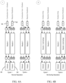
- the output of an exemplary pyrolysis system 100 having six reactors is shown in FIG. 5A , wherein the sequential opening of each mixing chamber outlet valve after each reaction cycle creates a sinusoidal dynamic output, resulting in a quasi steady-state output.
- the pyrolysis system includes reaction product sensors 70 which are located in the reaction product conduit 66 and are configured to monitor the hydrogen and carbon output from each reactor 1 .. n .
- the reaction product sensors 70 can be located downstream of a carbon separator and hydrogen separator (not shown).
- the reaction product sensors 70 can be selected from commercially available sensors suitable to detect certain properties of carbon and hydrogen gases, including mass or volumetric flow meters such as Coriolis, turbine and ultrasonic, gas composition sensors such as mass spectrometers, temperature sensors such as thermocouples and thermistors, and pressure sensors such as piezoresistive and variable capacitive sensors.
- the sensors 70 can be located elsewhere downstream of the mixing chamber 10, e.g. at the outlet valve 14 of each mixing chamber 10, or downstream of respective carbon and hydrogen separators (not shown) of the pyrolysis system.
- the controller 60 can be any type of programmable controller known in the art, such as a direct digital controller (DDC), a proportional integral derivative controller (PID), a programmable logic controller (PLC), an application specific integrated circuit (ASIC), or a general purpose computer.
- the controller 60 is communicative with the sensors 70 and receives hydrogen and carbon production measurements taken by the sensors 70.
- the controller 60 has a memory encoded with a pyrolysis operating program executable by the controller 60 to perform a normal pyrolysis operation when the measured hydrogen and carbon production is within a target hydrogen and carbon production specification, and to perform one or more of a lean burn operation and a rich burn operation when one or more of the hydrogen and carbon production is outside the target hydrogen and/or carbon production specification.
- the controller 60 adjusts the hydrogen and oxidant valves 36, 37 so that a stoichiometric air/fuel mixture is supplied to the combustion chamber 10.
- the fuel is methane
- the exact amount of oxygen required to completely consume the methane is 2 mol O 2 for every mol CH 4 and which is referred to as a stoichiometric mixture.
- the inside of the mixing chamber 10 may have become coated with carbon. It is theorized that a build up of carbon would effectively decrease the total gas volume of the mixing chamber 10, and consequently the pyrolysis system 100 cannot load as much feedstock into the mixing chamber 10, thus causing a decrease in the rate of hydrogen and carbon production. Also, the carbon buildup can cause the temperature inside the mixing chamber 10 to increase, since the combustion chamber 30 is a fixed volume, the same amount of energy from the combustion is added to a smaller amount of feedstock in the mixing chamber 10.
- the controller 60 executes a lean burn operation 88 and sets the fuel and oxidant valves 36, 37 to supply a lean fuel/oxidant mixture ( ⁇ ⁇ 0.9) to the combustion chamber 30. Because there is insufficient fuel to burn all the supplied oxidant, non-combusted oxidant (oxygen) will be introduced into the mixing chamber 10, which will react with the carbon on the walls and convert it to CO 2 and/or CO which would be removed or processed downstream.
- the lean burn operation can be run continuously (every reaction cycle) or periodically (every nth cycle) until the carbon and hydrogen production rates came back within the target specifications.
- the mixing chamber valve timing time between opening mixing chamber inlet valve 12 and opening mixing chamber outlet valve 14
- the reaction cycle timing is lower than the carbon residence time, which could result in lower carbon production or an undesirable change in carbon morphology.
- the controller 60 instead adjusts the fuel and oxidant valves 36, 37 to supply a rich fuel/oxidant mixture ( ⁇ > 1.1) to the combustion chamber (92). This will cause an incomplete combustion of the fuel and produce soot in the combustion chamber.
- the soot is a mass of carbon particles, and is injected into the mixing chamber 10 to seed carbon formation and reduce carbon residence time.
- a pyrolysis system 100 has a controller 60 encoded with a pyrolysis operating program that includes a de-fouling operation that is carried out in one or more reactors.
- a de-fouling operation is similar in purpose to a lean burn operation to remove carbon deposits in the mixing chamber, except that no fuel is supplied to the combustion chamber 30 and thus there is no ignition cycle.
- the equivalence ratio is zero in a de-fouling operation since the fuel/oxidant ratio is zero.
- Oxidant is fed to the combustion chamber 30 and then to the mixing chamber 10, and oxygen is allowed to react with the carbon deposits to form CO and CO 2 which are then discharged from the mixing chamber 10.
- an embodiment comprises a multiple reactor pyrolysis system 100 with a controller 60 programmed to sequentially execute a de-fouling cycle in each single reactor in the normal course of reactor reaction cycling (cycle 1 ... n) . Since the sequential firing of multiple reactors results in a quasi-steady-state output, taking one reactor offline for a single cycle is expected to minimally affect the product output stream. The de-fouling cycle is then repeated for each reactor in a separate sequence while the other reactors are still producing, thereby enabling the pyrolysis system 100 to perform a de-fouling operation on each one of its reactors without interrupting carbon and hydrogen production.
- the controller 60 executes the de-fouling operation for a reactor in a group of reactors 1.. n , as follows:
- Figure 5B illustrates how the de-fouling cycle can be interjected into the normal operating sequence with minimal effect on the process output.
- the sequencing of multiple reactors produces a nominal steady-state output, much like the firings of pistons in an internal combustion engine produce a steady output torque.
- a single reactor cycle may perform a de-fouling operation while the remainder of reactor operate as normal.
- the de-fouling operation can then be repeated or moved to the next reactor and this process can be repeated as necessary to clear the reactors of deposits.
- the output may have small temporal variations which are illustrated in Figure 5B in an exaggerated manner for to depict the effect of the de-fouling operation.
- the result is the ability to perform de-fouling maintenance routines while the process remains in an operational state.
- Coupled may have a number of different meanings depending on the context in which the terms are used.
- the terms coupled, or connected may have a mechanical or electrical meaning.
- the terms coupled, or connected may indicate that two elements or devices are connected to each other directly or via one or more intermediate elements or devices via electrical, or mechanical elements, depending on the particular context.
- the term “and/or” as used herein when used in association with a list of items refers to any one or more of the items comprising the list.
Landscapes
- Chemical & Material Sciences (AREA)
- Organic Chemistry (AREA)
- Chemical Kinetics & Catalysis (AREA)
- Engineering & Computer Science (AREA)
- Combustion & Propulsion (AREA)
- Health & Medical Sciences (AREA)
- Physics & Mathematics (AREA)
- Oil, Petroleum & Natural Gas (AREA)
- Inorganic Chemistry (AREA)
- Thermal Sciences (AREA)
- General Health & Medical Sciences (AREA)
- Automation & Control Theory (AREA)
- Life Sciences & Earth Sciences (AREA)
- General Chemical & Material Sciences (AREA)
- Molecular Biology (AREA)
- Analytical Chemistry (AREA)
- Biochemistry (AREA)
- Pathology (AREA)
- Immunology (AREA)
- General Physics & Mathematics (AREA)
- Materials Engineering (AREA)
- Hydrogen, Water And Hydrids (AREA)
- Regulation And Control Of Combustion (AREA)
- Carbon And Carbon Compounds (AREA)
- Processing Of Solid Wastes (AREA)
Applications Claiming Priority (1)
| Application Number | Priority Date | Filing Date | Title |
|---|---|---|---|
| US202263433567P | 2022-12-19 | 2022-12-19 |
Publications (1)
| Publication Number | Publication Date |
|---|---|
| EP4389854A1 true EP4389854A1 (fr) | 2024-06-26 |
Family
ID=87889354
Family Applications (1)
| Application Number | Title | Priority Date | Filing Date |
|---|---|---|---|
| EP23194678.1A Withdrawn EP4389854A1 (fr) | 2022-12-19 | 2023-08-31 | Procédés et systèmes pour ajuster des entrées dans un réacteur de pyrolyse pour améliorer les performances |
Country Status (6)
| Country | Link |
|---|---|
| US (1) | US12012333B1 (fr) |
| EP (1) | EP4389854A1 (fr) |
| JP (1) | JP7505100B1 (fr) |
| KR (1) | KR102760102B1 (fr) |
| CN (1) | CN118222319A (fr) |
| CA (1) | CA3210231C (fr) |
Citations (2)
| Publication number | Priority date | Publication date | Assignee | Title |
|---|---|---|---|---|
| US20060228290A1 (en) * | 2005-04-06 | 2006-10-12 | Cabot Corporation | Method to produce hydrogen or synthesis gas |
| US20220315424A1 (en) * | 2021-04-01 | 2022-10-06 | Modern Electron, Inc. | Systems and methods for local generation and/or consumption of hydrogen gas |
Family Cites Families (53)
| Publication number | Priority date | Publication date | Assignee | Title |
|---|---|---|---|---|
| FR2270201B1 (fr) | 1974-03-08 | 1976-10-08 | Siderurgie Fse Inst Rech | |
| US4123220A (en) | 1976-03-31 | 1978-10-31 | Ford, Bacon & Davis Texas, Inc. | Gas mixer and reactor |
| JPS59168091A (ja) | 1983-03-14 | 1984-09-21 | Mitsubishi Heavy Ind Ltd | 炭化水素からオレフインと合成ガスを製造するための熱分解法 |
| US5219530A (en) | 1991-02-15 | 1993-06-15 | Board Of Regents Of The University Of Washington | Apparatus for initiating pyrolysis using a shock wave |
| US5190739A (en) | 1991-02-27 | 1993-03-02 | Cabot Corporation | Production of carbon blacks |
| US5938975A (en) | 1996-12-23 | 1999-08-17 | Ennis; Bernard | Method and apparatus for total energy fuel conversion systems |
| US5864517A (en) | 1997-03-21 | 1999-01-26 | Adroit Systems, Inc. | Pulsed combustion acoustic wave generator |
| US5997596A (en) | 1997-09-05 | 1999-12-07 | Spectrum Design & Consulting International, Inc. | Oxygen-fuel boost reformer process and apparatus |
| WO1999058614A1 (fr) | 1998-05-08 | 1999-11-18 | Carbontech Holding As | Procede de production de matieres solides carbonees et de gaz riches en hydrogene |
| KR20010100008A (ko) | 1999-02-03 | 2001-11-09 | 추후제출 | 암모니아 합성으로부터 퍼지 가스를 사용하는 방법 |
| CA2379892A1 (fr) | 1999-07-29 | 2001-02-08 | David Systems & Technology S.L. | Convertisseur de plasma de combustibles fossiles en gaz riche en hydrogene |
| JP2001220102A (ja) | 2000-02-02 | 2001-08-14 | Matsumura Shuzo | 合成ガスの生成方法およびその装置 |
| FR2820416B1 (fr) | 2001-02-07 | 2003-12-05 | Cie D Etudes Des Technologies | Procede et dispositif pour la production d'hydrogene par oxydation partielle de carburants hydrocarbones |
| JP2003027241A (ja) | 2001-07-16 | 2003-01-29 | Korona Kk | プラズマ気相反応による二酸化炭素を可燃性ガスへ転化する方法 |
| FR2827591B1 (fr) | 2001-07-17 | 2004-09-10 | Cie D Etudes Des Technologies | Procede et dispositif de production d'un gaz riche en hydrogene par pyrolyse thermique d'hydrocarbures |
| EP1498387A1 (fr) | 2002-04-19 | 2005-01-19 | JFE Engineering Corporation | Procede de production d'hydrogene, appareil de production d'hydrogene, installations de fourniture d'hydrogene, et procede de production d'energie electrique |
| US6783749B2 (en) | 2002-05-13 | 2004-08-31 | The Boc Group, Inc. | Gas recovery process |
| JP3844226B2 (ja) | 2002-07-22 | 2006-11-08 | Jfeエンジニアリング株式会社 | 水素製造装置 |
| US6986870B1 (en) | 2002-09-11 | 2006-01-17 | University Of Central Florida Research Foundation, Inc | Combined methane decomposition and ammonia formation cell |
| US7323159B2 (en) | 2003-02-14 | 2008-01-29 | Uchicago Argonne, Llc | Method for fast start of a fuel processor |
| US7033569B2 (en) | 2003-02-24 | 2006-04-25 | Mc International Research | Process for the conversion of feedstocks and apparatus for performing the same |
| US7544342B2 (en) | 2004-08-25 | 2009-06-09 | The Boc Group, Inc. | Hydrogen production process |
| WO2006094137A1 (fr) | 2005-03-01 | 2006-09-08 | Saudi Arabian Oil Company | Méthode de décarbonisation à bord des carburants d'hydrocarbure dans un véhicule |
| AT502901B1 (de) | 2005-10-31 | 2009-08-15 | Electrovac Ag | Vorrichtung zur wasserstoffherstellung |
| US20110283705A1 (en) | 2006-07-24 | 2011-11-24 | Troy Oliver | EXPLO-DYNAMICS™: a method, system, and apparatus for the containment and conversion of explosive force into a usable energy resource |
| US7622087B2 (en) | 2006-11-16 | 2009-11-24 | H2Gen Innovations, Inc. | Reactor air supply system and burner configuration |
| WO2011022761A1 (fr) | 2009-08-25 | 2011-03-03 | Hope Cell Technologies Pty Ltd | Procédé et appareil pour la décomposition plasma de méthane et dautres hydrocarbures |
| US9187335B2 (en) | 2011-03-30 | 2015-11-17 | Altmerge, Llc | Pulse jet water desalination and purification |
| US8721980B2 (en) | 2011-03-30 | 2014-05-13 | Altmerge, Llc | Systems and methods of producing chemical compounds |
| WO2012134521A1 (fr) | 2011-03-30 | 2012-10-04 | Altmerge, Llc | Systèmes et procédés de fabrication de composés chimiques |
| DE102011106645A1 (de) | 2011-07-05 | 2013-01-10 | Linde Aktiengesellschaft | Verfahren zur Erzeugung von Koks |
| CN102583242B (zh) | 2012-03-09 | 2014-02-05 | 大连理工大学 | 一种催化裂解甲烷制备氢气的方法 |
| US20140058149A1 (en) | 2012-08-21 | 2014-02-27 | Uop Llc | High efficiency processes for olefins, alkynes, and hydrogen co-production from light hydrocarbons such as methane |
| US10138378B2 (en) | 2014-01-30 | 2018-11-27 | Monolith Materials, Inc. | Plasma gas throat assembly and method |
| US11939477B2 (en) | 2014-01-30 | 2024-03-26 | Monolith Materials, Inc. | High temperature heat integration method of making carbon black |
| US9574086B2 (en) | 2014-01-31 | 2017-02-21 | Monolith Materials, Inc. | Plasma reactor |
| JP6288506B2 (ja) | 2014-04-24 | 2018-03-07 | Jfeエンジニアリング株式会社 | 水素・炭素材料の製造方法及び製造装置 |
| WO2016099739A1 (fr) * | 2014-12-17 | 2016-06-23 | Exxonmobil Chemical Patents Inc. | Conversion d'hydrocarbures en éthylène |
| MX2017009982A (es) | 2015-02-03 | 2018-01-25 | Monolith Mat Inc | Metodo y dispositivo de enfriamiento regenerativo. |
| KR102705340B1 (ko) | 2015-02-03 | 2024-09-09 | 모놀리스 머티어리얼스 인코포레이티드 | 카본 블랙 생성 시스템 |
| CN108350281A (zh) | 2015-08-24 | 2018-07-31 | 巨石材料公司 | 制造炭黑的高温热集成方法 |
| CN106854127B (zh) | 2015-12-08 | 2021-03-12 | 清华大学 | 烃制乙炔和/或合成气的方法及装置 |
| JP2017197399A (ja) | 2016-04-27 | 2017-11-02 | 株式会社伊原工業 | 炭素循環利用システム |
| WO2017190045A1 (fr) | 2016-04-29 | 2017-11-02 | Monolith Materials, Inc. | Ajout de chaleur secondaire à un processus de production de particules et appareil |
| US11220428B2 (en) | 2017-01-31 | 2022-01-11 | New Wave Hydrogen, Inc. | Hydrocarbon wave reformer and methods of use |
| EP3592810A4 (fr) | 2017-03-08 | 2021-01-27 | Monolith Materials, Inc. | Systèmes et procédés de production de particules de carbone à l'aide un gaz de transfert thermique |
| US11020719B2 (en) | 2018-03-07 | 2021-06-01 | Sabic Global Technologies B.V. | Method and reactor for pyrolysis conversion of hydrocarbon gases |
| CA3131849A1 (fr) | 2018-04-03 | 2019-10-10 | Christopher J.-P. Cardinal | Systemes et procedes de traitement |
| KR102438787B1 (ko) * | 2018-12-10 | 2022-09-01 | 이코나 파워 인크. | 하나 이상의 생성물을 제조하기 위한 방법 및 반응기 |
| CA3170579C (fr) | 2020-12-15 | 2023-01-17 | Christopher Edwin John Reid | Procede de recyclage de carbone dans un reacteur de gaz d'alimentation |
| EP4015076A1 (fr) * | 2020-12-15 | 2022-06-22 | Ekona Power Inc. | Procédés de production d'un ou de plusieurs produits à l'aide d'un réacteur de gaz de charge |
| EP4347481A1 (fr) | 2021-06-04 | 2024-04-10 | Modern Electron, Inc. | Réacteurs combinés de combustion et de pyrolyse pour la production d'hydrogène et systèmes et méthodes associés |
| AU2022256206B2 (en) * | 2021-12-10 | 2024-02-22 | Ekona Power Inc. | Methods and systems for mixing fluids |
-
2023
- 2023-08-23 CA CA3210231A patent/CA3210231C/fr active Active
- 2023-08-31 EP EP23194678.1A patent/EP4389854A1/fr not_active Withdrawn
- 2023-09-21 CN CN202311224151.0A patent/CN118222319A/zh active Pending
- 2023-09-25 KR KR1020230128616A patent/KR102760102B1/ko active Active
- 2023-10-20 JP JP2023180892A patent/JP7505100B1/ja active Active
- 2023-11-09 US US18/505,943 patent/US12012333B1/en active Active
Patent Citations (2)
| Publication number | Priority date | Publication date | Assignee | Title |
|---|---|---|---|---|
| US20060228290A1 (en) * | 2005-04-06 | 2006-10-12 | Cabot Corporation | Method to produce hydrogen or synthesis gas |
| US20220315424A1 (en) * | 2021-04-01 | 2022-10-06 | Modern Electron, Inc. | Systems and methods for local generation and/or consumption of hydrogen gas |
Also Published As
| Publication number | Publication date |
|---|---|
| US12012333B1 (en) | 2024-06-18 |
| US20240208809A1 (en) | 2024-06-27 |
| JP7505100B1 (ja) | 2024-06-24 |
| KR102760102B1 (ko) | 2025-01-24 |
| KR20240096340A (ko) | 2024-06-26 |
| CA3210231A1 (fr) | 2023-12-29 |
| CN118222319A (zh) | 2024-06-21 |
| CA3210231C (fr) | 2024-03-12 |
| JP2024087767A (ja) | 2024-07-01 |
Similar Documents
| Publication | Publication Date | Title |
|---|---|---|
| KR101606310B1 (ko) | 가스 터빈 연소기의 퍼지 방법 및 퍼지 장치 | |
| RU2347143C2 (ru) | Система газотурбинного двигателя с рекуперацией и способ с применением каталитического горения | |
| NL2006221C2 (en) | Method for carbon black production using preheated feedstock and apparatus for same. | |
| EP1876217B1 (fr) | Retrait de dépôt de coke continu in situ par gazéification du flux catalytique | |
| KR20220085705A (ko) | 공급원료 가스 반응기를 사용하여 하나 이상의 생성물을 제조하는 방법 | |
| KR20010088805A (ko) | 통합 가스화 제어시스템 및 방법 | |
| CA3147241C (fr) | Systemes de four et procedes de craquage d'hydrocarbures | |
| US6715452B1 (en) | Method and apparatus for shutting down a fuel reformer | |
| US12012333B1 (en) | Methods and systems for adjusting inputs to a pyrolysis reactor to improve performance | |
| US20110289843A1 (en) | High temperature equalized pressure (htep) reactor | |
| US20240166508A1 (en) | Methods and systems for decomposing a feedstock gas | |
| JP5619785B2 (ja) | アルカン脱水素化の廃熱から一定量の蒸気を生成する方法及び装置 | |
| CN114901785A (zh) | 使用co2回路的热解气体产物的压缩 | |
| KR20240148869A (ko) | 수소 연료 및 탄화수소 연료를 연소시키기 위한 프로세스 및 장치 | |
| US11801485B2 (en) | Method and apparatus for controlling a reactor | |
| JPH0779959B2 (ja) | 多管式反応器 | |
| JP2022546399A (ja) | オキシ燃料燃焼プロセスにおける火炎制御 | |
| Serbin | Development of plasma-chemical combustion intensification systems for hydrocarbon fuels in marine power engineering | |
| US12017197B2 (en) | Method and apparatus for the production of chemical compounds | |
| RU2793799C2 (ru) | Способ и реактор для получения одного или нескольких продуктов | |
| US20260084959A1 (en) | Methods and systems for mitigating carbon fouling in a feedstock reactor | |
| JPH11263982A (ja) | スタートアップ/シャットダウンの運転制御装置 | |
| RU2744454C1 (ru) | Импульсно-детонационный способ получения алкенов и алкинов и устройство для его реализации | |
| CN119140014A (zh) | 用于分解原料的方法和系统 | |
| JP4402606B2 (ja) | 水熱反応利用重質油改質方法及び水熱反応利用重質油改質装置 |
Legal Events
| Date | Code | Title | Description |
|---|---|---|---|
| PUAI | Public reference made under article 153(3) epc to a published international application that has entered the european phase |
Free format text: ORIGINAL CODE: 0009012 |
|
| STAA | Information on the status of an ep patent application or granted ep patent |
Free format text: STATUS: REQUEST FOR EXAMINATION WAS MADE |
|
| STAA | Information on the status of an ep patent application or granted ep patent |
Free format text: STATUS: EXAMINATION IS IN PROGRESS |
|
| 17P | Request for examination filed |
Effective date: 20240326 |
|
| AK | Designated contracting states |
Kind code of ref document: A1 Designated state(s): AL AT BE BG CH CY CZ DE DK EE ES FI FR GB GR HR HU IE IS IT LI LT LU LV MC ME MK MT NL NO PL PT RO RS SE SI SK SM TR |
|
| 17Q | First examination report despatched |
Effective date: 20240613 |
|
| STAA | Information on the status of an ep patent application or granted ep patent |
Free format text: STATUS: THE APPLICATION IS DEEMED TO BE WITHDRAWN |
|
| 18D | Application deemed to be withdrawn |
Effective date: 20250715 |