EP4389984B1 - Agencement de mât pour un engin de chantier et procédé associé - Google Patents
Agencement de mât pour un engin de chantier et procédé associé Download PDFInfo
- Publication number
- EP4389984B1 EP4389984B1 EP22215371.0A EP22215371A EP4389984B1 EP 4389984 B1 EP4389984 B1 EP 4389984B1 EP 22215371 A EP22215371 A EP 22215371A EP 4389984 B1 EP4389984 B1 EP 4389984B1
- Authority
- EP
- European Patent Office
- Prior art keywords
- mast
- base
- extension
- assembly according
- drive
- Prior art date
- Legal status (The legal status is an assumption and is not a legal conclusion. Google has not performed a legal analysis and makes no representation as to the accuracy of the status listed.)
- Active
Links
Images

Classifications
-
- E—FIXED CONSTRUCTIONS
- E02—HYDRAULIC ENGINEERING; FOUNDATIONS; SOIL SHIFTING
- E02D—FOUNDATIONS; EXCAVATIONS; EMBANKMENTS; UNDERGROUND OR UNDERWATER STRUCTURES
- E02D7/00—Methods or apparatus for placing sheet pile bulkheads, piles, mouldpipes, or other moulds
- E02D7/02—Placing by driving
- E02D7/06—Power-driven drivers
- E02D7/14—Components for drivers inasmuch as not specially for a specific driver construction
- E02D7/16—Scaffolds or supports for drivers
-
- E—FIXED CONSTRUCTIONS
- E02—HYDRAULIC ENGINEERING; FOUNDATIONS; SOIL SHIFTING
- E02D—FOUNDATIONS; EXCAVATIONS; EMBANKMENTS; UNDERGROUND OR UNDERWATER STRUCTURES
- E02D13/00—Accessories for placing or removing piles or bulkheads, e.g. noise attenuating chambers
- E02D13/04—Guide devices; Guide frames
-
- E—FIXED CONSTRUCTIONS
- E02—HYDRAULIC ENGINEERING; FOUNDATIONS; SOIL SHIFTING
- E02D—FOUNDATIONS; EXCAVATIONS; EMBANKMENTS; UNDERGROUND OR UNDERWATER STRUCTURES
- E02D7/00—Methods or apparatus for placing sheet pile bulkheads, piles, mouldpipes, or other moulds
- E02D7/02—Placing by driving
- E02D7/06—Power-driven drivers
- E02D7/14—Components for drivers inasmuch as not specially for a specific driver construction
- E02D7/16—Scaffolds or supports for drivers
- E02D7/165—Scaffolds or supports for drivers of variable length, e.g. foldable or telescopic
-
- E—FIXED CONSTRUCTIONS
- E21—EARTH OR ROCK DRILLING; MINING
- E21B—EARTH OR ROCK DRILLING; OBTAINING OIL, GAS, WATER, SOLUBLE OR MELTABLE MATERIALS OR A SLURRY OF MINERALS FROM WELLS
- E21B7/00—Special methods or apparatus for drilling
- E21B7/02—Drilling rigs characterised by means for land transport with their own drive, e.g. skid mounting or wheel mounting
- E21B7/023—Drilling rigs characterised by means for land transport with their own drive, e.g. skid mounting or wheel mounting the mast being foldable or telescopically retractable
Definitions
- the invention relates to a mast arrangement for a construction machine with a base mast which has a linear guide for displaceably guiding a work carriage along the base mast, a mast extension which is detachably attachable to an underside of the base mast for extending the base mast and the linear guide downwards, and a connecting device with which the mast extension is detachably attached to the base mast, according to the preamble of claim 1.
- the invention further relates to a method for extending a base mast with a linear guide downwards with a mast extension, according to the preamble of claim 15.
- Mast arrangements with a mast which has a linear guide on its front side for the sliding guidance of a work carriage are frequently used on construction machinery, as can be seen from the publication DE 84 35 121 U1 is known.
- a rotary drilling drive, a vibrator or a ram can be arranged on the work carriage in order to carry out a civil engineering process.
- the mast assembly is usually mounted on a preferably mobile carrier device via a linkage mechanism.
- the linkage mechanism allows the mast assembly to be adjusted vertically to a certain extent.
- the mast assembly is designed to be as tall as possible in order to accommodate correspondingly long drilling tools, bored piles, or sheet piles.
- the mast assembly may extend as far down as possible, close to the ground surface.
- the linkage mechanisms on construction machinery are not designed to lower a single mast or leader assembly close to the ground surface, for example due to the design of the carrier device.
- relatively long work tools such as a sledgehammer for driving planks, to increase the travel range along the mast.
- a mast extension to the underside of a base mast.
- Such a mast extension can usually have a length of 1 to 3 meters.
- the mast extension must be positioned accordingly on the underside and fastened manually using screw bolts. This is time-consuming and labor-intensive.
- the invention is based on the object of specifying a mast arrangement and a method with which a mast extension can be carried out particularly efficiently.
- the mast arrangement is provided with the connecting device being arranged within the base mast and/or the mast extension and comprising at least one actuating device with which at least one locking element can be adjusted between a retracted unlocking position, in which the mast extension is released from the base mast, and an extended locking position, in which the mast extension is firmly held and locked to the base mast by the at least one locking element.
- a basic idea of the invention is to provide a connecting device with an activatable actuating device, with which one or preferably several locking elements can be adjusted between a retracted unlocking position within a receiving space of the base mast and/or the mast extension and a locking position in which the mast extension is locked to the base mast by the one or several locking elements and
- the actuating device can be operated manually, for example via a manual drive element, such as a hand crank, or via an energy-driven drive to adjust one or more locking elements.
- the connecting device with the actuating device is arranged on the base mast and/or the mast extension in such a way that, immediately after the mast extension has been fed to the underside of the base mast, wherein an axial plug-in connection can initially be formed, the firm connection can be made by simply activating the actuating device.
- the actuating device In the fed position, the actuating device is located within the base mast and/or the mast extension. This protects the connecting device and also saves space. In this way, a mast extension can be safely and quickly attached and removed from a base mast of a mast arrangement.
- the mast arrangement can be formed solely from the base mast or as a multi-part mast arrangement, in particular as a telescopic leader arrangement.
- a preferred embodiment of the invention consists in that the actuating device comprises a rotatably mounted threaded spindle on which the at least one locking element is adjustably mounted. Via a threaded spindle, a rotary movement can be converted into a linear adjustment movement of the at least one locking element, corresponding to a spindle drive.
- a spindle drive is structurally simple and space-saving.
- a particularly compact actuating device can be achieved according to a further development of the invention in that the threaded spindle is designed with an external thread and/or an internal thread, which engages with a corresponding internal thread or external thread on the locking element for adjusting the locking element.
- This achieves a spindle drive with which a rotary movement of the threaded spindle is converted into an axial displacement movement of the at least one locking element.
- the threaded spindle has at least one external thread, on which a sleeve- or cup-shaped locking element with a matching internal thread on its inside sits.
- the threaded spindle can also be completely or partially tubular, with an internal thread formed on the inside.
- a rod-shaped element of the locking element with a suitable external toothing can engage into this to form a spindle drive.
- the compactness of the arrangement can be further improved by providing the threaded spindle with two opposing external threads and/or internal threads in its end region, each of which has a locking element arranged for movement in opposite directions.
- two locking elements can be extended in opposite directions or retracted toward each other.
- a further preferred embodiment of the invention consists in that the locking element is designed as a bolt or a sleeve which can be inserted into corresponding receiving holes on the base mast and/or the mast extension for locking.
- the locking element is preferably cylindrical on its outer side and can be inserted into correspondingly matching receiving holes on the base mast and/or the mast extension.
- Coaxial receiving holes are preferably arranged on the base mast and the mast extension in order to achieve particularly good locking.
- One or more axially directed centering elements, in particular centering bolts can also be arranged on the mast extension and can be inserted into corresponding centering holes on the underside of the base mast for axial centering and alignment of the two mast parts.
- the centering bolts can also be arranged in reverse on the base mast, and the mounting holes can then be arranged accordingly on the mast extension. If the bolt is sleeve-shaped or tubular, it can have a closed base or a cover cap on its front side.
- the actuating device has at least one drive section, via which a drive force for adjusting the locking element can be applied.
- Driving force can be generated manually by an operator or by means of a drive, in particular a motor.
- the drive section is formed on a threaded spindle for applying a torque.
- the threaded spindle can be set in a rotational movement via the drive section, with an axial adjusting movement of the at least one locking element being effected via a spindle drive formed by the threaded spindle.
- the drive section is designed as a drive pin or drive hole on one end face of the threaded spindle.
- a drive pin can be, for example, a polygonal pin, in particular a square pin, or a screw head.
- a drive hole can also be designed as an internal polygonal hole, such as an internal square or hexagonal hole, through which torque can be introduced directly into the threaded spindle.
- a further preferred embodiment of the invention is that the drive section comprises a drive wheel on the threaded spindle.
- the drive wheel can be arranged on an end face or in a central region of the threaded spindle.
- the drive wheel can, in particular, have a toothing that meshes with another gear, such as a pinion, of a drive. It is also possible to drive the drive wheel via a chain.
- the movement device can be driven manually, for example via a hand crank or a hand-operated tool.
- an energy-driven drive in particular an electric rotary motor
- a hydraulically or pneumatically operated drive in particular a hydraulic rotary motor
- the drive can be permanently attached or can be fed to the actuating device.
- a so-called cordless screwdriver with a corresponding drive element can be used by an operator to drive the actuating device for locking and/or unlocking.
- particularly efficient actuation can be achieved by arranging at least two actuating elements, in particular two or more threaded spindles, parallel to one another. Particularly when multiple threaded spindles are arranged, these can be operated either individually or jointly via a drive, for example, when drive wheels on the threaded spindles are meshingly connected to one another. Depending on the desired strength of the connection, a corresponding number of actuating devices with locking elements can be arranged.
- a further preferred embodiment of the invention consists in providing an adapter unit which is arranged on the underside of the base mast and is designed to receive the at least one fastening device.
- an adapter unit in particular conventional masts can be retrofitted to construction machinery.
- the adapter unit can be attached, in particular screwed, to the underside of the base mast.
- the adapter unit can be part of the connecting device with which the mast extension is attached to the base mast via the adapter unit.
- the adapter unit can represent the part of the connecting device formed on the base mast, with which the corresponding part of the connecting device is attached to the mast extension.
- the base mast can be formed by a single mast. It is preferred that a work carriage is mounted on a front side of the base mast so as to be linearly movable.
- the mast arrangement can also be designed such that the base mast is a mast element of a telescopic leader arrangement.
- a telescopic leader arrangement can have a first mast element with a first linear guide as a guide mast, on which a second mast element is displaceably, i.e. telescopically, mounted as a possible base mast.
- the mast extension can preferably be arranged on this displaceable second mast element.
- a mast extension is also arranged according to the invention on the first mast element of the telescopic leader arrangement.
- the telescopic leader arrangement has a guide mast as a first mast element, along in which the base mast is displaceably mounted as a second mast element, that the mast extension is attached to the base mast and that at least one support roller is mounted on the mast extension, which can be supported on the guide mast when the base mast is moved.
- the base mast which is displaceably mounted on a guide mast, can be extended downwards.
- Reliable guidance and support relative to the guide mast during displacement can be achieved on the mast extension in that at least one support roller, preferably two or more support rollers, are arranged on the mast extension, preferably in a lower region of the mast extension.
- the at least one support roller can come into contact with a guide surface of the guide mast when the base mast is moved and can thus be supported relative to the guide mast. This allows safe guidance of the base mast with the mast extension on the guide mast.
- the invention further comprises a construction machine, in particular a piling rig, with a, in particular movable, support unit, wherein a mast arrangement according to the invention is arranged on the support unit.
- the piling rig can have a percussion or hammer device for performing a piling operation.
- the hammer device can be arranged on the work carriage.
- the construction machine can also be a drilling rig with a drilling rig carriage that can be moved along the mast or a diaphragm wall cutter with a linearly guided diaphragm wall cutter, a vibrator with a vibration drive that can be moved along the mast or another civil engineering machine with a base mast with linear guide.
- the construction machine can be designed with a stationary carrier unit.
- the carrier unit is movable, and may, in particular, have a crawler chassis, a wheeled chassis, or a rail-mounted chassis.
- the method according to the invention for extending a base mast is characterized in that a mast arrangement according to the invention, as described above, is used with a connecting device.
- a mast arrangement according to the invention as described above, is used with a connecting device.
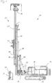
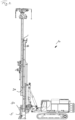
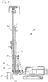
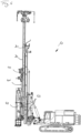
- a mast arrangement 20 according to the invention on a construction machine 10 is shown in the Figures 1 to 4 shown.
- the construction machine 10 has a carrier unit 12, which, according to the illustrated embodiment, can have a mobile undercarriage 13 and a superstructure 14 rotatably mounted thereon.
- An operating cabin for a machine operator can be arranged on the superstructure 14.
- the mast arrangement 10 according to the invention can be adjustably mounted on the carrier unit 12 via a basically known articulation mechanism 16 with adjustment cylinders 17.
- the mast arrangement 10 can, according to the illustrated embodiment, be designed as a telescopic leader arrangement 21.
- the mast holder 28 is connected to the articulation mechanism 16.
- a base mast 30 with a linear guide 32 on its front side can be slidably mounted along the guide mast 22.
- the base mast 30 can be slidably mounted relative to the guide mast 22 via a drive device (not shown in detail).
- a work carriage 40 is slidably mounted and guided along the linear guide 32 of the base mast 30.
- the work device carriage 40 is designed to hold a Figure 1 not shown, such as a drilling drive, a vibrating device or the like.
- a mast head 34 can be arranged on the top side of the base mast 30, which can, for example, have deflection rollers for a support cable for moving the work carriage 40.
- a mast extension 50 can be attached to an underside of the base mast 30, wherein the mast extension 50 Figure 1 shown before assembly and accommodated in a frame 5 for transport and assembly.
- the frame 5 with the mast extension 50 is positioned on the mast assembly 10 below the base mast 30, as clearly shown in Figure 2 is shown.
- the base mast 30 can now be moved downwards to the mast extension 50, which is set up on the ground by means of the frame 5, and brought into contact with it.
- the mast extension 50 can then be attached to the underside of the base mast 30, so that the Mast extension 50 can be moved with the base mast 30 along the guide mast 22, as clearly shown in Figure 3
- the frame 5 can be removed after the mast extension 50 has been installed.
- the frame 5 can be reinserted in a similar manner to receive and hold the mast extension 50 when the mast extension 50 is dismantled.
- the Figure 3 It can be seen in particular that at least one support roller 56 can be arranged in a lower region of the mast extension 50, which support roller can come into contact with a guide surface of the guide mast 22 when the base mast 30 is moved upwards with the mast extension 50.
- the mast extension 50 can have a front linear guide 52, which can be flush with the linear guide 32 of the base mast 30.
- the linear guide 52 on the mast extension 50 can in particular be designed such that it represents an extension of the linear guide 32 of the base mast 30.
- the work carriage 40 and/or a work device can be guided by the base mast 30 up to a lower region of the mast extension 50 and can also be moved along the linear guide 52.
- the work carriage 40 and/or a work device arranged thereon can be moved into a position close to the ground.
- the impact device 42 can have its own carriage 43 with guide shoes, which can cooperate with the linear guide 32 on the base mast 30 and the linear guide 52 on the mast extension 50 for guiding displacement.
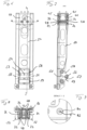
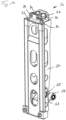
- a mast extension 50 for a mast arrangement 20 according to the invention is further described in connection with the Figures 5 to 11 explained.
- a rod-shaped mast extension 50 with two front linear guides 52 and support rollers 56 at a lower area is shown.
- FIG. 5 An adapter unit 44 with an internal cavity is arranged on the upper side of the mast extension 50.
- the adapter unit 44 can generally be pre-attached to the underside of the base mast 30 by means of the schematically shown Connecting elements 45 are attached.
- Connecting elements 45 are attached for quick attachment of the mast extension 50 to the adapter unit 44 of the base mast 30.
- a connecting device 60 is provided, which in the illustrated embodiment comprises two actuating devices 70, which will be described in more detail below.
- Two guide rails are located along the mast extension 50 to form the linear guide 52, which can continue on the adapter unit 44 and the base mast 30.
- the Figures 6 to 8 The arrangement of two support rollers 56 can be seen, which can be mounted on a lower region of the mast extension 50 on a toggle lever mechanism 57 that can be adjusted to the longitudinal direction of the mast extension 50.
- the toggle lever mechanism 57 can have an upper toggle lever 58 and a lower toggle lever 59, which are articulated to one another in the region of a roller axis of the support rollers 56.
- the lower toggle lever 59 can be articulated to the mast extension 50, while the upper toggle lever 58 can be mounted so that it can be displaced longitudinally in a slot 55 on the mast extension 50, in addition to being articulated.
- the upper toggle lever 58 can be axially positioned and thus the toggle lever mechanism 57 can be adjusted, at which position the support rollers 56 protrude transversely to the longitudinal direction of the mast and come into secure contact with the guide mast 22 of a telescopic leader arrangement 21.
- the toggle lever mechanism 57 allows changes in position and adjustments of the support rollers 56 to be carried out or absorbed flexibly.
- the connecting device 60 is arranged on the top side of the mast extension 50, which according to the Figure 11 In the illustrated embodiment, it may comprise two parallel actuating devices 70.
- the actuating devices 70 each have a threaded spindle 74, which is rotatably mounted on parallel bearing plates 62 on the mast extension.
- a sleeve-shaped locking element 72 is slidably mounted at both ends.
- an internal thread is arranged in each case, which meshes with a corresponding external thread of a threaded section on the threaded spindle 74.
- two opposite threaded sections with oppositely directed external threads are arranged on each threaded spindle 74, so that upon a rotational movement of the threaded spindle, the locking elements 72 are each moved in the opposite direction.
- the locking elements 72 can be moved from an inwardly retracted unlocking position, which is in the Figures 7 and 8 shown, can be moved outward into a locking position. In the locking position, the locking elements 72 each engage in a corresponding locking hole 48, which can be formed on the adapter unit 44.
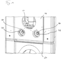
- a rotary movement can be applied to one end face of each threaded spindle 74 via a drive section 80 via a correspondingly designed drive hole 82 or a drive pin via a drive device (not shown).
- the drive section 80 is particularly shown in the enlarged illustration according to Figure 7
- the drive device can be a hand-operated tool, such as a crank, or a device with a drive motor, such as a cordless screwdriver.
- the locking holes 48 can, in principle, also be formed directly on a lower portion of the base mast 30.
- a simple retrofitting or conversion of an existing base mast 30 can be achieved by means of an adapter unit 44, which is pre-attached to the underside of the base mast 30 to establish the connection.
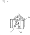
- an adapter unit 44 is clearly shown in Figure 12 shown.
- the adapter unit 44 can be attached to the underside of the base mast 30 via connecting elements 45, which can preferably have screws.
- the preferably screw-like connecting elements 45 can be actuated from the side or preferably from below through an internal cavity of the adapter unit 44.
- the connecting device 60 with the actuating devices 70 on the mast extension 50 can be inserted into the inner receiving space or cavity of the adapter unit 44. Once the mast extension 50 is placed in the connecting position on the base mast 30 and is axially aligned, the actuating devices 70 operated, whereby the locking elements 72 are extended outward into the corresponding locking holes 48 on the adapter unit 44. This allows a reliable multi-point locking to be achieved.
- the actuating devices 70 can be actuated in the correspondingly reversed manner, whereby the locking elements 72 are retracted inward by means of the threaded spindle 74 and thus withdrawn from the locking holes 48. In this position, the mast extension 50 can be pulled downward again and, in particular, re-received in the frame 5 according to Figures 1 and 2.
- a securing and/or detection device can be arranged, which ensures or checks whether the mast extension 50 is securely received in the frame 5 upon release.
Landscapes
- Engineering & Computer Science (AREA)
- Mining & Mineral Resources (AREA)
- Life Sciences & Earth Sciences (AREA)
- General Life Sciences & Earth Sciences (AREA)
- Paleontology (AREA)
- Civil Engineering (AREA)
- General Engineering & Computer Science (AREA)
- Structural Engineering (AREA)
- Geology (AREA)
- Fluid Mechanics (AREA)
- Environmental & Geological Engineering (AREA)
- Geochemistry & Mineralogy (AREA)
- Physics & Mathematics (AREA)
- Earth Drilling (AREA)
Claims (15)
- Agencement de mât pour une machine de construction (10) avec- un mât de base (30) qui présente un guide linéaire (32) pour guider de manière coulissante un chariot de travail (40) le long du mât de base (30),- un prolongement de mât (50), qui peut être monté de manière amovible sur un côté inférieur du mât de base (30) pour prolonger le mât de base (30) et le guide linéaire (32) vers le bas, et- un dispositif de liaison (60) avec lequel le prolongement de mât (50) est monté de manière amovible sur le mât de base (30),caractérisé en ce que
le dispositif de liaison (60) est agencé à l'intérieur du mât de base (30) et/ou du prolongement de mât (50) et comprend au moins un dispositif d'actionnement (70) avec lequel au moins un élément de verrouillage (72) peut être réglé entre une position de déverrouillage rétractée, dans laquelle le prolongement de mât (50) est détaché du mât de base (30), et une position de verrouillage déployée dans laquelle le prolongement de mât (50) est fermement maintenu et verrouillé sur le mât de base (30) par l'au moins un élément de verrouillage (72). - Agencement de mât selon la revendication 1,
caractérisé en ce que
le dispositif d'actionnement (70) présente une broche filetée (74) montée rotative, sur laquelle l'au moins un élément de verrouillage (72) est monté de manière réglable. - Agencement de mât selon la revendication 2,
caractérisé en ce que
la broche filetée (74) est réalisée avec un filetage extérieur et/ou un filetage intérieur qui, pour le réglage de l'élément de verrouillage (72), est en prise avec un filetage intérieur ou un filetage extérieur correspondant sur l'élément de verrouillage (72). - Agencement de mât selon la revendication 3,
caractérisé en ce que
la broche filetée (74) présente deux filetages extérieurs et/ou deux filetages intérieurs orientés à l'opposé dans sa zone d'extrémité, sur chacun desquels un élément de verrouillage (72) est agencé pour se déplacer dans des directions opposées. - Agencement de mât selon l'une quelconque des revendications 1 à 4,
caractérisé en ce que
l'élément de verrouillage (72) est réalisé sous la forme d'un boulon ou d'une douille qui peut être inséré dans des trous de réception correspondants (38) sur le mât de base (30) et/ou le prolongement de mât (50) pour le verrouillage. - Agencement de mât selon l'une quelconque des revendications 1 à 5,
caractérisé en ce que
le dispositif d'actionnement (70) présente au moins une section d'entraînement (80) par l'intermédiaire de laquelle une force d'entraînement peut être appliquée pour régler l'élément de verrouillage (72). - Agencement de mât selon la revendication 6,
caractérisé en ce que
la section d'entraînement (80) est réalisée sur une broche filetée (74) pour appliquer un couple de rotation. - Agencement de mât selon la revendication 7,
caractérisé en ce que
la section d'entraînement (80) est réalisée sous la forme d'un tenon d'entraînement ou d'un trou d'entraînement (82) sur un côté frontal de la broche filetée (74). - Agencement de mât selon l'une quelconque des revendications 1 à 8,
caractérisé en ce que,
pour entraîner le dispositif d'actionnement (70), un entraînement alimenté en énergie, notamment un moteur électrique rotatif, est monté ou peut être agencé si nécessaire. - Agencement de mât selon l'une quelconque des revendications 1 à 9,
caractérisé en ce qu'
au moins deux dispositifs d'actionnement (70), notamment deux ou plus de deux broches filetées (74), sont agencés parallèlement les uns aux autres. - Agencement de mât selon l'une quelconque des revendications 1 à 10,
caractérisé en ce qu'
il est prévu une unité d'adaptation (44) qui est agencée sur le côté inférieur du mât de base (30) et qui est réalisée pour recevoir l'au moins un dispositif d'actionnement (70). - Agencement de mât selon l'une quelconque des revendications 1 à 11,
caractérisé en ce que
le mât de base (30) est un élément de mât d'un agencement de mât télescopique (21). - Agencement de mât selon la revendication 12,
caractérisé en ce quel'agencement de mât télescopique (21) présente, en tant que premier élément de mât, un mât de guidage le long duquel le mât de base (30) est monté de manière coulissante en tant que deuxième élément de mât,en ce que le prolongement de mât est monté sur le mât de base (30) eten ce qu'au moins un galet d'appui est monté sur le prolongement de mât (50), lequel peut s'appuyer sur le mât de guidage (22) lors d'un coulissement du mât de base (30). - Machine de construction, notamment engin de battage, avec une unité de support (12), notamment déplaçable,
caractérisé en ce qu'
un agencement de mât (20) selon l'une quelconque des revendications 1 à 13 est agencé sur l'unité de support (12). - Procédé pour prolonger un mât de base (30) avec un guide linéaire (32) vers le bas avec un prolongement de mât,
caractérisé en ce qu'
un agencement de mât (20) selon l'une quelconque des revendications 1 à 13 est utilisé avec un dispositif de liaison (60).
Priority Applications (1)
| Application Number | Priority Date | Filing Date | Title |
|---|---|---|---|
| EP22215371.0A EP4389984B1 (fr) | 2022-12-21 | 2022-12-21 | Agencement de mât pour un engin de chantier et procédé associé |
Applications Claiming Priority (1)
| Application Number | Priority Date | Filing Date | Title |
|---|---|---|---|
| EP22215371.0A EP4389984B1 (fr) | 2022-12-21 | 2022-12-21 | Agencement de mât pour un engin de chantier et procédé associé |
Publications (3)
| Publication Number | Publication Date |
|---|---|
| EP4389984A1 EP4389984A1 (fr) | 2024-06-26 |
| EP4389984C0 EP4389984C0 (fr) | 2025-04-02 |
| EP4389984B1 true EP4389984B1 (fr) | 2025-04-02 |
Family
ID=84569210
Family Applications (1)
| Application Number | Title | Priority Date | Filing Date |
|---|---|---|---|
| EP22215371.0A Active EP4389984B1 (fr) | 2022-12-21 | 2022-12-21 | Agencement de mât pour un engin de chantier et procédé associé |
Country Status (1)
| Country | Link |
|---|---|
| EP (1) | EP4389984B1 (fr) |
Citations (5)
| Publication number | Priority date | Publication date | Assignee | Title |
|---|---|---|---|---|
| JPS5989189U (ja) | 1982-12-08 | 1984-06-16 | 株式会社松沢基工 | 掘削機のリ−ダ−マスト |
| JPH02161013A (ja) | 1988-12-12 | 1990-06-20 | Ishikawajima Kenki Kk | 伸縮式リーダー |
| CN101907156A (zh) | 2009-06-04 | 2010-12-08 | 王博 | 双层双向螺杆 |
| EP2769954A1 (fr) | 2013-02-21 | 2014-08-27 | Manitowoc Crane Companies, LLC | Débrancheur de connexions de grue |
| EP3440271B1 (fr) | 2016-04-08 | 2020-02-12 | Junttan OY | Guide, machine de battage de pieu, et procédé pour accroître la fonctionnalité d'une machine de battage de pieu |
Family Cites Families (4)
| Publication number | Priority date | Publication date | Assignee | Title |
|---|---|---|---|---|
| DE3303262A1 (de) * | 1983-02-01 | 1984-08-02 | Fried. Krupp Gmbh, 4300 Essen | Maekler fuer den anbau an den ausleger eines baggers |
| DE8435121U1 (de) * | 1984-11-30 | 1985-05-02 | Fa. Josef Messmann, 2990 Papenburg | Vorrichtung zum Verbinden eines von einem Seilzug hebbar gehaltenen Mäklers einer Ramme mit einem Mäklerhalter |
| EP3919684B1 (fr) * | 2020-06-04 | 2024-08-07 | BAUER Maschinen GmbH | Excavateur et procédé de création d'une fente dans le sol |
| EP4083327B1 (fr) * | 2021-04-29 | 2025-12-03 | BAUER Maschinen GmbH | Engin de génie civil |
-
2022
- 2022-12-21 EP EP22215371.0A patent/EP4389984B1/fr active Active
Patent Citations (5)
| Publication number | Priority date | Publication date | Assignee | Title |
|---|---|---|---|---|
| JPS5989189U (ja) | 1982-12-08 | 1984-06-16 | 株式会社松沢基工 | 掘削機のリ−ダ−マスト |
| JPH02161013A (ja) | 1988-12-12 | 1990-06-20 | Ishikawajima Kenki Kk | 伸縮式リーダー |
| CN101907156A (zh) | 2009-06-04 | 2010-12-08 | 王博 | 双层双向螺杆 |
| EP2769954A1 (fr) | 2013-02-21 | 2014-08-27 | Manitowoc Crane Companies, LLC | Débrancheur de connexions de grue |
| EP3440271B1 (fr) | 2016-04-08 | 2020-02-12 | Junttan OY | Guide, machine de battage de pieu, et procédé pour accroître la fonctionnalité d'une machine de battage de pieu |
Non-Patent Citations (2)
| Title |
|---|
| ANONYMOUS: "100kN-55 9-R-Trapezoidal screw ZE-Series Screw jack", ZIMM, 23 September 2021 (2021-09-23), XP093356854, Retrieved from the Internet <URL:https://en-us.zimm.com/product/100kn-55x9-r-trapezoidal-screw-ze/> |
| COOPER HANDLING GROUP LTD: "Mantsinen Quick Coupler for Attachments - More Load, Less Energy", 12 March 2020 (2020-03-12), XP093356855, Retrieved from the Internet <URL:https://www.youtube.com/watch?v=0wBZX-EH4-M> |
Also Published As
| Publication number | Publication date |
|---|---|
| EP4389984C0 (fr) | 2025-04-02 |
| EP4389984A1 (fr) | 2024-06-26 |
Similar Documents
| Publication | Publication Date | Title |
|---|---|---|
| EP2133508B1 (fr) | Appareil de construction doté d'un mât téléscopique et procédé de fonctionnement d'un tel appareil | |
| DE19811813B4 (de) | Seitliche Auslegerverriegelung | |
| DE2528129C2 (de) | Teleskopausleger | |
| EP3910160B1 (fr) | Accouplement de tige de forage et procédé de fonctionnement de l'accouplement de tige de forage | |
| WO1992019837A2 (fr) | Foreuse-sol | |
| EP2304179B1 (fr) | Appareil de forage et de mise en place de boulons d'ancrage comprenant des glissières séparées | |
| DE10123403A1 (de) | Bauarbeitsgerät | |
| DE1477357B2 (de) | Vorrichtung zum spannen und loesen von in der spindel eines bohr und fraeswerks aufgenommenen werkzeugen | |
| DE20105578U1 (de) | Verriegelungseinheit für einen Teleskopausleger eines Krans und Teleskopausleger | |
| DE19641193C2 (de) | Teleskopausleger, insbesondere für stationäre oder fahrbare Krane | |
| EP4311881B1 (fr) | Roue de fraisage pour une fraise pour rideaux souterrains et procédé de transformation d'une roue de fraisage | |
| DE2906155C3 (de) | Support mit zwei Trägern und einer Gleitführung | |
| EP3299522B1 (fr) | Dispositif de forage et procédé d'établissement d'un forage | |
| EP4389984A1 (fr) | Agencement de mât pour un engin de chantier et procédé associé | |
| EP3868516A1 (fr) | Machine-outil portative | |
| EP1795697B1 (fr) | Dispositif pour le travail du sol | |
| DE4038424C1 (en) | Kelly borehole drilling arrangement - involves telescopically nested pipes connected to drill head | |
| DE2420567B2 (de) | Wickelmaschine für Bandmaterial insbesondere Metallband | |
| EP2395153B1 (fr) | Procédé et dispositif de fabrication de lamelles murales dans le sol | |
| EP3456914B1 (fr) | Dispositif de forage double tête et procédé de réalisation d'un forage | |
| DE10243744B4 (de) | Verschiebevorrichtung und Baumaschine mit Verschiebevorrichtung | |
| EP4112816A1 (fr) | Appareil d'excavation de tranchées pour parois moulées et procédé d'excavation d'une paroi moulée dans le sol | |
| DE3438145C1 (de) | Bohrfutter,insbesondere Schlagbohrfutter | |
| DE102023132882B3 (de) | Bohrständer zur Aufnahme, Anordnung und/oder Führung einer Bohrmaschine | |
| EP4467723B1 (fr) | Dispositif d'introduction pour introduire un élément de fondation |
Legal Events
| Date | Code | Title | Description |
|---|---|---|---|
| PUAI | Public reference made under article 153(3) epc to a published international application that has entered the european phase |
Free format text: ORIGINAL CODE: 0009012 |
|
| STAA | Information on the status of an ep patent application or granted ep patent |
Free format text: STATUS: REQUEST FOR EXAMINATION WAS MADE |
|
| 17P | Request for examination filed |
Effective date: 20230615 |
|
| AK | Designated contracting states |
Kind code of ref document: A1 Designated state(s): AL AT BE BG CH CY CZ DE DK EE ES FI FR GB GR HR HU IE IS IT LI LT LU LV MC ME MK MT NL NO PL PT RO RS SE SI SK SM TR |
|
| GRAP | Despatch of communication of intention to grant a patent |
Free format text: ORIGINAL CODE: EPIDOSNIGR1 |
|
| STAA | Information on the status of an ep patent application or granted ep patent |
Free format text: STATUS: GRANT OF PATENT IS INTENDED |
|
| INTG | Intention to grant announced |
Effective date: 20241127 |
|
| GRAS | Grant fee paid |
Free format text: ORIGINAL CODE: EPIDOSNIGR3 |
|
| GRAA | (expected) grant |
Free format text: ORIGINAL CODE: 0009210 |
|
| STAA | Information on the status of an ep patent application or granted ep patent |
Free format text: STATUS: THE PATENT HAS BEEN GRANTED |
|
| AK | Designated contracting states |
Kind code of ref document: B1 Designated state(s): AL AT BE BG CH CY CZ DE DK EE ES FI FR GB GR HR HU IE IS IT LI LT LU LV MC ME MK MT NL NO PL PT RO RS SE SI SK SM TR |
|
| REG | Reference to a national code |
Ref country code: GB Ref legal event code: FG4D Free format text: NOT ENGLISH |
|
| REG | Reference to a national code |
Ref country code: CH Ref legal event code: EP |
|
| REG | Reference to a national code |
Ref country code: IE Ref legal event code: FG4D Free format text: LANGUAGE OF EP DOCUMENT: GERMAN |
|
| REG | Reference to a national code |
Ref country code: DE Ref legal event code: R096 Ref document number: 502022003411 Country of ref document: DE |
|
| U01 | Request for unitary effect filed |
Effective date: 20250410 |
|
| U07 | Unitary effect registered |
Designated state(s): AT BE BG DE DK EE FI FR IT LT LU LV MT NL PT RO SE SI Effective date: 20250424 |
|
| PG25 | Lapsed in a contracting state [announced via postgrant information from national office to epo] |
Ref country code: ES Free format text: LAPSE BECAUSE OF FAILURE TO SUBMIT A TRANSLATION OF THE DESCRIPTION OR TO PAY THE FEE WITHIN THE PRESCRIBED TIME-LIMIT Effective date: 20250402 |
|
| PG25 | Lapsed in a contracting state [announced via postgrant information from national office to epo] |
Ref country code: NO Free format text: LAPSE BECAUSE OF FAILURE TO SUBMIT A TRANSLATION OF THE DESCRIPTION OR TO PAY THE FEE WITHIN THE PRESCRIBED TIME-LIMIT Effective date: 20250702 Ref country code: GR Free format text: LAPSE BECAUSE OF FAILURE TO SUBMIT A TRANSLATION OF THE DESCRIPTION OR TO PAY THE FEE WITHIN THE PRESCRIBED TIME-LIMIT Effective date: 20250703 |
|
| PG25 | Lapsed in a contracting state [announced via postgrant information from national office to epo] |
Ref country code: PL Free format text: LAPSE BECAUSE OF FAILURE TO SUBMIT A TRANSLATION OF THE DESCRIPTION OR TO PAY THE FEE WITHIN THE PRESCRIBED TIME-LIMIT Effective date: 20250402 |
|
| PG25 | Lapsed in a contracting state [announced via postgrant information from national office to epo] |
Ref country code: HR Free format text: LAPSE BECAUSE OF FAILURE TO SUBMIT A TRANSLATION OF THE DESCRIPTION OR TO PAY THE FEE WITHIN THE PRESCRIBED TIME-LIMIT Effective date: 20250402 |
|
| PG25 | Lapsed in a contracting state [announced via postgrant information from national office to epo] |
Ref country code: RS Free format text: LAPSE BECAUSE OF FAILURE TO SUBMIT A TRANSLATION OF THE DESCRIPTION OR TO PAY THE FEE WITHIN THE PRESCRIBED TIME-LIMIT Effective date: 20250702 |
|
| RAP2 | Party data changed (patent owner data changed or rights of a patent transferred) |
Owner name: BAUER MASCHINEN GMBH |
|
| U1K | Transfer of rights of the unitary patent after the registration of the unitary effect |
Owner name: BAUER MASCHINEN GMBH; DE |
|
| PG25 | Lapsed in a contracting state [announced via postgrant information from national office to epo] |
Ref country code: IS Free format text: LAPSE BECAUSE OF FAILURE TO SUBMIT A TRANSLATION OF THE DESCRIPTION OR TO PAY THE FEE WITHIN THE PRESCRIBED TIME-LIMIT Effective date: 20250802 |
|
| PLBI | Opposition filed |
Free format text: ORIGINAL CODE: 0009260 |
|
| PG25 | Lapsed in a contracting state [announced via postgrant information from national office to epo] |
Ref country code: SM Free format text: LAPSE BECAUSE OF FAILURE TO SUBMIT A TRANSLATION OF THE DESCRIPTION OR TO PAY THE FEE WITHIN THE PRESCRIBED TIME-LIMIT Effective date: 20250402 |
|
| REG | Reference to a national code |
Ref country code: CH Ref legal event code: L10 Free format text: ST27 STATUS EVENT CODE: U-0-0-L10-L00 (AS PROVIDED BY THE NATIONAL OFFICE) Effective date: 20260114 |
|
| PLAX | Notice of opposition and request to file observation + time limit sent |
Free format text: ORIGINAL CODE: EPIDOSNOBS2 |
|
| PG25 | Lapsed in a contracting state [announced via postgrant information from national office to epo] |
Ref country code: CZ Free format text: LAPSE BECAUSE OF FAILURE TO SUBMIT A TRANSLATION OF THE DESCRIPTION OR TO PAY THE FEE WITHIN THE PRESCRIBED TIME-LIMIT Effective date: 20250402 |
|
| U20 | Renewal fee for the european patent with unitary effect paid |
Year of fee payment: 4 Effective date: 20251216 |
|
| PG25 | Lapsed in a contracting state [announced via postgrant information from national office to epo] |
Ref country code: SK Free format text: LAPSE BECAUSE OF FAILURE TO SUBMIT A TRANSLATION OF THE DESCRIPTION OR TO PAY THE FEE WITHIN THE PRESCRIBED TIME-LIMIT Effective date: 20250402 |
|
| 26 | Opposition filed |
Opponent name: JUNTTAN OY Effective date: 20251231 |
|
| PLBB | Reply of patent proprietor to notice(s) of opposition received |
Free format text: ORIGINAL CODE: EPIDOSNOBS3 |
|
| PG25 | Lapsed in a contracting state [announced via postgrant information from national office to epo] |
Ref country code: MC Free format text: LAPSE BECAUSE OF FAILURE TO SUBMIT A TRANSLATION OF THE DESCRIPTION OR TO PAY THE FEE WITHIN THE PRESCRIBED TIME-LIMIT Effective date: 20250402 |
|
| REG | Reference to a national code |
Ref country code: CH Ref legal event code: H13 Free format text: ST27 STATUS EVENT CODE: U-0-0-H10-H13 (AS PROVIDED BY THE NATIONAL OFFICE) Effective date: 20260723 |