EP4390041A1 - Ensemble de transmission pour actionner un joint de porte automatique et joint de porte comprenant ledit ensemble de transmission - Google Patents
Ensemble de transmission pour actionner un joint de porte automatique et joint de porte comprenant ledit ensemble de transmission Download PDFInfo
- Publication number
- EP4390041A1 EP4390041A1 EP22216147.3A EP22216147A EP4390041A1 EP 4390041 A1 EP4390041 A1 EP 4390041A1 EP 22216147 A EP22216147 A EP 22216147A EP 4390041 A1 EP4390041 A1 EP 4390041A1
- Authority
- EP
- European Patent Office
- Prior art keywords
- gear
- trigger
- movement mechanism
- housing
- force
- Prior art date
- Legal status (The legal status is an assumption and is not a legal conclusion. Google has not performed a legal analysis and makes no representation as to the accuracy of the status listed.)
- Pending
Links
Images


Classifications
-
- E—FIXED CONSTRUCTIONS
- E06—DOORS, WINDOWS, SHUTTERS, OR ROLLER BLINDS IN GENERAL; LADDERS
- E06B—FIXED OR MOVABLE CLOSURES FOR OPENINGS IN BUILDINGS, VEHICLES, FENCES OR LIKE ENCLOSURES IN GENERAL, e.g. DOORS, WINDOWS, BLINDS, GATES
- E06B7/00—Special arrangements or measures in connection with doors or windows
- E06B7/16—Sealing arrangements on wings or parts co-operating with the wings
- E06B7/18—Sealing arrangements on wings or parts co-operating with the wings by means of movable edgings, e.g. draught sealings additionally used for bolting, e.g. by spring force or with operating lever
- E06B7/20—Sealing arrangements on wings or parts co-operating with the wings by means of movable edgings, e.g. draught sealings additionally used for bolting, e.g. by spring force or with operating lever automatically withdrawn when the wing is opened, e.g. by means of magnetic attraction, a pin or an inclined surface, especially for sills
- E06B7/215—Sealing arrangements on wings or parts co-operating with the wings by means of movable edgings, e.g. draught sealings additionally used for bolting, e.g. by spring force or with operating lever automatically withdrawn when the wing is opened, e.g. by means of magnetic attraction, a pin or an inclined surface, especially for sills with sealing strip being moved to a retracted position by elastic means, e.g. springs
-
- E—FIXED CONSTRUCTIONS
- E06—DOORS, WINDOWS, SHUTTERS, OR ROLLER BLINDS IN GENERAL; LADDERS
- E06B—FIXED OR MOVABLE CLOSURES FOR OPENINGS IN BUILDINGS, VEHICLES, FENCES OR LIKE ENCLOSURES IN GENERAL, e.g. DOORS, WINDOWS, BLINDS, GATES
- E06B7/00—Special arrangements or measures in connection with doors or windows
- E06B7/16—Sealing arrangements on wings or parts co-operating with the wings
- E06B7/18—Sealing arrangements on wings or parts co-operating with the wings by means of movable edgings, e.g. draught sealings additionally used for bolting, e.g. by spring force or with operating lever
- E06B7/20—Sealing arrangements on wings or parts co-operating with the wings by means of movable edgings, e.g. draught sealings additionally used for bolting, e.g. by spring force or with operating lever automatically withdrawn when the wing is opened, e.g. by means of magnetic attraction, a pin or an inclined surface, especially for sills
- E06B7/21—Sealing arrangements on wings or parts co-operating with the wings by means of movable edgings, e.g. draught sealings additionally used for bolting, e.g. by spring force or with operating lever automatically withdrawn when the wing is opened, e.g. by means of magnetic attraction, a pin or an inclined surface, especially for sills with sealing strip movable in plane of wing
-
- E—FIXED CONSTRUCTIONS
- E06—DOORS, WINDOWS, SHUTTERS, OR ROLLER BLINDS IN GENERAL; LADDERS
- E06B—FIXED OR MOVABLE CLOSURES FOR OPENINGS IN BUILDINGS, VEHICLES, FENCES OR LIKE ENCLOSURES IN GENERAL, e.g. DOORS, WINDOWS, BLINDS, GATES
- E06B7/00—Special arrangements or measures in connection with doors or windows
- E06B7/16—Sealing arrangements on wings or parts co-operating with the wings
- E06B7/22—Sealing arrangements on wings or parts co-operating with the wings by means of elastic edgings, e.g. elastic rubber tubes; by means of resilient edgings, e.g. felt or plush strips, resilient metal strips
- E06B7/23—Plastic, sponge rubber, or like strips or tubes
- E06B7/2316—Plastic, sponge rubber, or like strips or tubes used as a seal between the floor and the wing
Definitions
- the present invention relates to a gear arrangement with a gear for actuating an automatic door seal and a door seal with this gear arrangement.
- Automatic door seals are used, in particular, to seal a gap between the lower end of a door leaf and a floor in doors without thresholds, so that noise, smoke, flames and/or air cannot pass through this gap.
- Automatic door seals have a sealing strip with a sealing element, usually a sealing profile, which is pressed against the floor when the door is closed to seal the gap, and which is lifted off the floor when it is open to release the gap so that the door leaf can be moved without the sealing element dragging on the floor.
- Such seals can also be provided at other points on doors, for example at the upper end of a door, for example to seal a gap between the door leaf and a door frame in the case of non-rebated door leaves, or a gap between the door leaf and the ceiling in the case of floor-to-ceiling doors.
- the seals have a movement mechanism to move the sealing strip between a sealing position and a release position.
- This movement mechanism is connected to a trigger.
- This trigger can be used to introduce a force into the movement mechanism to move the sealing strip from the release position to the sealing position.
- the movement mechanism is also equipped with a reset mechanism. which usually has a return spring.
- a return spring can instead be an integral part of the movement mechanism, for example a leaf spring to which the sealing strip is attached and which bends when force is introduced into the trigger and thus into the movement mechanism.
- the return spring moves the sealing strip into the release position and applies the necessary force.
- the return force counteracts the movement of the sealing strip into the sealing position. Therefore, when the sealing strip moves into the sealing position, the return force applied by the return spring in particular must be overcome.
- the trigger usually protrudes over the door leaf on one narrow side. When a door is closed, it then hits the door frame or another fixed element and is thereby pressed in. This principle is used for both swing doors and sliding doors.
- the invention was based on the object of finding a solution to reduce the effect of the return spring against the closing force applied when closing a sliding door.
- Such a gear arrangement can be used with an automatic door seal as stated in claim 9 or in an automatic door seal as stated in claim 10.
- a gear arrangement designed according to the invention it is possible to reduce the force required to actuate the door seal. Since the force for moving the sealing strip from the release position to the sealing position when closing the sliding door is not introduced into the movement mechanism directly or via a trigger on the door seal, but via the gear arrangement, it is possible to use the gear arrangement to reduce the force.
- the gear ratio of the gear is selected to be greater than 1 in order to reduce the external force required to move the sealing strip from the release position to the sealing position.
- the trigger of the gear arrangement has to cover a greater distance to move the sealing strip than the trigger of a door seal without a gear arrangement according to the invention.
- the advantages of the lower force expenditure outweigh the longer actuation path.
- the trigger of a gear arrangement can have an output structure and a first gear element of the gear elements can have a drive structure and the output structure of the trigger can interact with the drive structure to transmit a force from the trigger to the first gear element.
- the trigger can be slidably mounted.
- the output structure of the trigger can be a gear rack or part of a gear rack.
- the first gear element can be rotatably mounted.
- the drive structure of the first gear element can be a first gear ring or part of a first gear ring that meshes with the gear rack or part of the gear rack.
- the first transmission element can have an output structure and a second transmission element of the transmission elements can have a drive structure.
- the output structure of the first transmission element can interact directly or indirectly with the drive structure of the second drive to transmit a force from the first transmission element to the second transmission element. In the case of direct interaction, the force is transmitted directly from the first to the second transmission element. In the case of indirect interaction, the force is transmitted from the first to the second transmission element via further transmission elements.
- the first gear element can have a second gear ring or part of a second gear ring as the output structure.
- the radius of the second gear ring can be smaller than the radius of the first gear ring.
- the second gear element can also be mounted so that it can rotate. It can have a third gear ring or part of a third gear ring as a drive element. The second gear ring or part thereof can mesh with the third gear ring or part thereof.
- the second transmission element can have an output structure in addition to the drive structure and the transmission element can have a drive structure.
- the output structure of the second transmission element can cooperate with the drive structure of the transmission element to transmit a force from the second transmission element to the transmission element.
- the output structure of the second transmission element can be the third gear ring or a fourth gear ring or a part of the fourth gear ring, in which case the radius of the fourth gear ring is smaller than the radius of the third gear ring.
- the first gear element it is also possible for the first gear element to have only one gear ring, which meshes with both the output structure of the trigger and the third gear ring of the second gear element or part of the third gear ring.
- the second gear element must have the fourth gear ring or part of it in addition to the third gear ring or part of it.
- At least one of the drive structures and/or at least one of the output structures is a rack, a part of a rack, a gear ring or a part of a gear ring.
- a gear arrangement according to the invention can have a housing in or on which the trigger, the at least one gear element and the transmission element are mounted so as to be rotatable or linearly displaceable.
- the trigger can protrude from the housing on a first side through a first opening so that a force can be introduced into the trigger from the outside.
- the housing can have a second opening on a side of the housing opposite the first opening, from which the transmission element protrudes and/or through which the connecting structure of the transmission element is accessible in order to connect it to a trigger or a movement mechanism.
- the housing of the gear arrangement is arranged in the sealing element. This particularly facilitates the installation of the two housings in a groove in a door leaf.
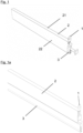
- the automatic door seal according to the invention has two fastening brackets 1 (only one of which is shown), a housing 2, a movement mechanism, a sealing strip 3, 6 with a support profile 6 and a sealing profile 3 as a sealing element and a gear arrangement 7 according to the invention.
- the housing 2 of the seal, the movement mechanism and the sealing strip 6 can basically be designed in the same way as a known automatic door seal.
- the housing 2 can in particular be a profile with a largely uniform cross-section, in particular an extruded profile made of aluminum or plastic.
- the movement mechanism of which only one rod 51 is shown in the figures, can in particular be a movement mechanism with scissor elements or with leaf springs. If a movement mechanism with scissor elements is selected, the seal also has a return spring. If the movement mechanism is a mechanism with leaf springs, the return spring is formed by the leaf springs and is thus an integral part of the movement mechanism.
- the support profile 6 of the sealing strip can also be a profile with a largely uniform cross-section, in particular an extruded profile made of aluminum or plastic.
- the support profile is attached to the movement mechanism and it carries the Sealing profile 3. This can in particular be drawn into the support profile 6 or glued to the support profile 6.
- the sealing profile 3 consists of an elastomer.
- the elastomer can be silicone.
- the sealing profile 3 can also be designed in a known manner.
- the support profile 6 is notched at one end of the seal on the trigger side in order to create space for the gear arrangement 7 in the release position of the sealing strip 3, 6.
- the housing 2 is essentially U-shaped and has a web 21 that connects ends of two outer legs 22 that run essentially parallel to one another.
- a channel is formed in the housing 2 by two legs 23 that protrude inwards from the outer legs 22.
- the rod 51 of the movement mechanism is arranged so as to be displaceable and guided in this channel 2.
- the fastening angles 1, via which the seal can be attached to a door leaf, can be inserted into the ends of the channel.
- a housing 73, 74 and a transmission element 72 of the gear arrangement 7 are inserted into the channel.
- the housing 73, 74 of the gear arrangement has holding structures 741 for this purpose and the transmission element 72 has guide structures 741 that engage in the channel of the housing 2.
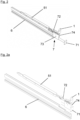
- the rod 51 of the movement mechanism is movable in the direction of the longitudinal extension of the housing 2. This longitudinal movement of the rod 51 is converted by the remaining part of the movement mechanism (not shown) into a transverse movement of the sealing strip 3, 6 between the release position and the sealing position.
- the rod 51 is not directly connected to a trigger via which a force to actuate the movement mechanism in the seal in order to move the sealing strip 3, 6 from the release position into the sealing position.
- the gear arrangement 7 according to the invention is connected to the rod 51 of the movement mechanism, which in turn has a trigger 71.
- the rod 51 can be designed like the corresponding rod of a known seal.
- a thread 511 is provided on a trigger-side end of the rod, onto which the trigger of the seal is screwed in known seals and which in the seal according to the invention is connected to the gear arrangement 7, namely to the transmission element 72 of the gear arrangement 7.
- the gear arrangement 7 has the trigger 71, the housing 73, 74 with the housing cover 73 as another part of the housing, a housing shell 74, the transmission element 72 and a first gear element 75 and a second gear element 76.
- the trigger 71, the two gear elements 75, 76 and the transmission element 72 form a gear.
- the trigger 71 is the element of the gear into which a force is introduced and the transmission element 72 is the part of the gear to which a larger force is output.
- the gear has a gear ratio that is greater than 1.
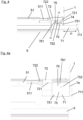
- the trigger 71 is slidably mounted in the housing 73, 74 of the gear arrangement 7. It protrudes from a first opening on the front side of the housing 73, 74. By applying force to the trigger 71, it can be moved linearly into or in the housing 73, 74. To move the sealing strip 3, 6 from the release position to the sealing position, the trigger 71 must be moved by a distance of length l1.
- the trigger 71 has a rack 711 in at least one area in the housing 73, 74.
- the trigger 71 can release the absorbed force via this rack 711.
- the rack 711 thus forms an output structure of the trigger 71.
- the first gear element 75 is rotatably mounted in the housing 73, 74 of the gear arrangement 7 and has a part of a first gear ring 751 with a first radius r1 around the axis of rotation of the first gear element 75.
- This part of the first gear ring 751 forms a drive structure via which the force emitted by the trigger 71 is introduced into the first gear element 75.
- the drive structure of the first gear element 75 meshes with the rack 711 of the trigger 71.
- the first gear element 75 also has a second gear ring 712. This has a second radius r2 around the axis of rotation of the first gear part 75, which is smaller than the first radius r1.
- the second gear ring 752 forms an output structure of the first gear element 75.
- the angular velocity at the first gear ring 751 or at the drive structure of the first gear element 75 is translated into a smaller angular velocity at the second gear ring 752 or at the output structure of the first gear element 75.
- the torque absorbed at the drive structure is translated into a larger torque at the output structure.
- the second gear element 76 is a gear with a third gear ring 761 with a third radius r3 around a rotation axis of the second gear element.
- the second gear element is also rotatably mounted in the housing of the gear arrangement.
- the third radius r3 corresponds to the second radius r2.
- the third gear ring 761 is both the drive structure and the output structure. of the second gear element 76.
- the second gear element 76 does not change the torque. There is only a reversal of direction.
- the transmission element 72 has a rack 721, which is a drive structure of the transmission element 72.
- the third gear ring 761 of the second gear element 76 meshes with this rack 721.
- the torque on the third gear ring 761 is converted into a corresponding force on the rack 721.
- Due to the transmission by means of the first gear element 75, the force is greater than the force introduced into the trigger 71.
- the distance that the transmission element 72 travels when the trigger 71 is actuated is also smaller than the distance that the trigger 71 travels.
- the transmission element 72 has a threaded hole. With this, it is screwed onto the rod 51 of the movement mechanism. The movement of the transmission element 72 is thereby introduced directly into the rod 51 and thus into the movement mechanism of the seal according to the invention.
Landscapes
- Engineering & Computer Science (AREA)
- Civil Engineering (AREA)
- Structural Engineering (AREA)
- Specific Sealing Or Ventilating Devices For Doors And Windows (AREA)
Priority Applications (1)
| Application Number | Priority Date | Filing Date | Title |
|---|---|---|---|
| EP22216147.3A EP4390041A1 (fr) | 2022-12-22 | 2022-12-22 | Ensemble de transmission pour actionner un joint de porte automatique et joint de porte comprenant ledit ensemble de transmission |
Applications Claiming Priority (1)
| Application Number | Priority Date | Filing Date | Title |
|---|---|---|---|
| EP22216147.3A EP4390041A1 (fr) | 2022-12-22 | 2022-12-22 | Ensemble de transmission pour actionner un joint de porte automatique et joint de porte comprenant ledit ensemble de transmission |
Publications (1)
| Publication Number | Publication Date |
|---|---|
| EP4390041A1 true EP4390041A1 (fr) | 2024-06-26 |
Family
ID=84569828
Family Applications (1)
| Application Number | Title | Priority Date | Filing Date |
|---|---|---|---|
| EP22216147.3A Pending EP4390041A1 (fr) | 2022-12-22 | 2022-12-22 | Ensemble de transmission pour actionner un joint de porte automatique et joint de porte comprenant ledit ensemble de transmission |
Country Status (1)
| Country | Link |
|---|---|
| EP (1) | EP4390041A1 (fr) |
Citations (3)
| Publication number | Priority date | Publication date | Assignee | Title |
|---|---|---|---|---|
| BE395382A (fr) * | 1933-03-31 | 1933-04-29 | Symons Charles | Simo-plinth |
| CN209855627U (zh) * | 2018-09-30 | 2019-12-27 | 广东威法定制家居股份有限公司 | 密封隔音门 |
| CN111502509A (zh) * | 2020-06-18 | 2020-08-07 | 安徽智扬门业有限公司 | 一种密封静音门 |
-
2022
- 2022-12-22 EP EP22216147.3A patent/EP4390041A1/fr active Pending
Patent Citations (3)
| Publication number | Priority date | Publication date | Assignee | Title |
|---|---|---|---|---|
| BE395382A (fr) * | 1933-03-31 | 1933-04-29 | Symons Charles | Simo-plinth |
| CN209855627U (zh) * | 2018-09-30 | 2019-12-27 | 广东威法定制家居股份有限公司 | 密封隔音门 |
| CN111502509A (zh) * | 2020-06-18 | 2020-08-07 | 安徽智扬门业有限公司 | 一种密封静音门 |
Similar Documents
| Publication | Publication Date | Title |
|---|---|---|
| AT402838B (de) | Dichtungsvorrichtung, insbesondere für türflügel | |
| DE3124106C2 (fr) | ||
| EP1884614A2 (fr) | Agencement de charnière | |
| EP2474698A2 (fr) | Dispositif d'étanchéité doté d'un profil d'étanchéité et d'un mécanisme destiné au déplacement du profil d'étanchéité lors de l'actionnement du mécanisme | |
| EP2050918B1 (fr) | Joint descendant doté d'une ouverture de passage | |
| EP3868994B1 (fr) | Joint d'étanchéité pourvu de modules comportant un mécanisme d'abaissement | |
| EP4390041A1 (fr) | Ensemble de transmission pour actionner un joint de porte automatique et joint de porte comprenant ledit ensemble de transmission | |
| EP1635023A1 (fr) | Mécanisme pivotant pour portes | |
| DE3112310C2 (de) | Lüftungsvorrichtung | |
| DE10147477B4 (de) | Schließfolgeregler | |
| EP2672046A2 (fr) | Agencement de rail de guidage | |
| DE19851517C1 (de) | Fixiervorrichtung | |
| DE202006005996U1 (de) | Schwimmerbetätigte Schließvorrichtung zum Abschotten einer Gebäudeöffnung | |
| DE10035378B4 (de) | Dichtungsanordnung für eine schwellenlose Türe | |
| DE19532817A1 (de) | Türschließer mit einem Teleskoparm | |
| DE2160369C2 (de) | Begrenzungspuffer für die Aufwickelbewegung von Rolladenpanzern od. dgl. | |
| EP3985219B1 (fr) | Agencement doté d'un joint d'étanchéité de plancher pour une porte, un espace intermédiaire se trouvant entre un battant de porte et un cadre, dans lequel passe le seul axe de rotation du battant | |
| EP3085876B1 (fr) | Dispositif de joint descendant | |
| EP4276267B1 (fr) | Joint d'étanchéité, notamment pour portes coulissantes ou portes coulissantes | |
| DE29820770U1 (de) | Dichtungsvorrichtung für den unteren Spalt bei Türen bzw. Toren | |
| DE2420178A1 (de) | Lukenverschluss, z.b. lukenverschluss mit bodentreppe | |
| EP4242412B1 (fr) | Joint d'étanchéité doté d'une baguette d'étanchéité mobile à l'aide d'un mécanisme de mise en mouvement, le mécanisme de mise en mouvement étant actionnable au moyen d'un actionneur au moins partiellement pivotant | |
| DE102013000969C5 (de) | Schließfolgeregelungseinrichtung für eine zweiflügelige Tür | |
| DE102020206544B4 (de) | Gestänge für einen Türschließer oder Türantrieb, Türschließer oder Türantrieb sowie Tür | |
| DE202004005162U1 (de) | Bodendichtung mit Federband |
Legal Events
| Date | Code | Title | Description |
|---|---|---|---|
| PUAI | Public reference made under article 153(3) epc to a published international application that has entered the european phase |
Free format text: ORIGINAL CODE: 0009012 |
|
| STAA | Information on the status of an ep patent application or granted ep patent |
Free format text: STATUS: THE APPLICATION HAS BEEN PUBLISHED |
|
| AK | Designated contracting states |
Kind code of ref document: A1 Designated state(s): AL AT BE BG CH CY CZ DE DK EE ES FI FR GB GR HR HU IE IS IT LI LT LU LV MC ME MK MT NL NO PL PT RO RS SE SI SK SM TR |
|
| STAA | Information on the status of an ep patent application or granted ep patent |
Free format text: STATUS: REQUEST FOR EXAMINATION WAS MADE |
|
| 17P | Request for examination filed |
Effective date: 20250102 |
|
| GRAP | Despatch of communication of intention to grant a patent |
Free format text: ORIGINAL CODE: EPIDOSNIGR1 |
|
| STAA | Information on the status of an ep patent application or granted ep patent |
Free format text: STATUS: GRANT OF PATENT IS INTENDED |
|
| INTG | Intention to grant announced |
Effective date: 20251218 |
|
| GRAS | Grant fee paid |
Free format text: ORIGINAL CODE: EPIDOSNIGR3 |
|
| GRAA | (expected) grant |
Free format text: ORIGINAL CODE: 0009210 |
|
| STAA | Information on the status of an ep patent application or granted ep patent |
Free format text: STATUS: THE PATENT HAS BEEN GRANTED |