EP4390467B1 - Accessoires passifs - Google Patents
Accessoires passifs Download PDFInfo
- Publication number
- EP4390467B1 EP4390467B1 EP22307015.2A EP22307015A EP4390467B1 EP 4390467 B1 EP4390467 B1 EP 4390467B1 EP 22307015 A EP22307015 A EP 22307015A EP 4390467 B1 EP4390467 B1 EP 4390467B1
- Authority
- EP
- European Patent Office
- Prior art keywords
- user
- borne
- orientation
- magnetic object
- location
- Prior art date
- Legal status (The legal status is an assumption and is not a legal conclusion. Google has not performed a legal analysis and makes no representation as to the accuracy of the status listed.)
- Active
Links
Images




Classifications
-
- G—PHYSICS
- G01—MEASURING; TESTING
- G01B—MEASURING LENGTH, THICKNESS OR SIMILAR LINEAR DIMENSIONS; MEASURING ANGLES; MEASURING AREAS; MEASURING IRREGULARITIES OF SURFACES OR CONTOURS
- G01B7/00—Measuring arrangements characterised by the use of electric or magnetic techniques
- G01B7/004—Measuring arrangements characterised by the use of electric or magnetic techniques for measuring coordinates of points
-
- G—PHYSICS
- G01—MEASURING; TESTING
- G01V—GEOPHYSICS; GRAVITATIONAL MEASUREMENTS; DETECTING MASSES OR OBJECTS; TAGS
- G01V3/00—Electric or magnetic prospecting or detecting; Measuring magnetic field characteristics of the earth, e.g. declination, deviation
- G01V3/08—Electric or magnetic prospecting or detecting; Measuring magnetic field characteristics of the earth, e.g. declination, deviation operating with magnetic or electric fields produced or modified by objects or geological structures or by detecting devices
- G01V3/081—Electric or magnetic prospecting or detecting; Measuring magnetic field characteristics of the earth, e.g. declination, deviation operating with magnetic or electric fields produced or modified by objects or geological structures or by detecting devices the magnetic field is produced by the objects or geological structures
-
- G—PHYSICS
- G06—COMPUTING OR CALCULATING; COUNTING
- G06F—ELECTRIC DIGITAL DATA PROCESSING
- G06F1/00—Details not covered by groups G06F3/00 - G06F13/00 and G06F21/00
- G06F1/16—Constructional details or arrangements
- G06F1/1613—Constructional details or arrangements for portable computers
- G06F1/1615—Constructional details or arrangements for portable computers with several enclosures having relative motions, each enclosure supporting at least one I/O or computing function
- G06F1/1616—Constructional details or arrangements for portable computers with several enclosures having relative motions, each enclosure supporting at least one I/O or computing function with folding flat displays, e.g. laptop computers or notebooks having a clamshell configuration, with body parts pivoting to an open position around an axis parallel to the plane they define in closed position
-
- G—PHYSICS
- G06—COMPUTING OR CALCULATING; COUNTING
- G06F—ELECTRIC DIGITAL DATA PROCESSING
- G06F1/00—Details not covered by groups G06F3/00 - G06F13/00 and G06F21/00
- G06F1/16—Constructional details or arrangements
- G06F1/1613—Constructional details or arrangements for portable computers
- G06F1/1633—Constructional details or arrangements of portable computers not specific to the type of enclosures covered by groups G06F1/1615 - G06F1/1626
- G06F1/1675—Miscellaneous details related to the relative movement between the different enclosures or enclosure parts
- G06F1/1677—Miscellaneous details related to the relative movement between the different enclosures or enclosure parts for detecting open or closed state or particular intermediate positions assumed by movable parts of the enclosure, e.g. detection of display lid position with respect to main body in a laptop, detection of opening of the cover of battery compartment
-
- G—PHYSICS
- G06—COMPUTING OR CALCULATING; COUNTING
- G06F—ELECTRIC DIGITAL DATA PROCESSING
- G06F1/00—Details not covered by groups G06F3/00 - G06F13/00 and G06F21/00
- G06F1/16—Constructional details or arrangements
- G06F1/1613—Constructional details or arrangements for portable computers
- G06F1/1633—Constructional details or arrangements of portable computers not specific to the type of enclosures covered by groups G06F1/1615 - G06F1/1626
- G06F1/1675—Miscellaneous details related to the relative movement between the different enclosures or enclosure parts
- G06F1/1683—Miscellaneous details related to the relative movement between the different enclosures or enclosure parts for the transmission of signal or power between the different housings, e.g. details of wired or wireless communication, passage of cabling
-
- G—PHYSICS
- G06—COMPUTING OR CALCULATING; COUNTING
- G06F—ELECTRIC DIGITAL DATA PROCESSING
- G06F1/00—Details not covered by groups G06F3/00 - G06F13/00 and G06F21/00
- G06F1/16—Constructional details or arrangements
- G06F1/1613—Constructional details or arrangements for portable computers
- G06F1/1633—Constructional details or arrangements of portable computers not specific to the type of enclosures covered by groups G06F1/1615 - G06F1/1626
- G06F1/1684—Constructional details or arrangements related to integrated I/O peripherals not covered by groups G06F1/1635 - G06F1/1675
- G06F1/169—Constructional details or arrangements related to integrated I/O peripherals not covered by groups G06F1/1635 - G06F1/1675 the I/O peripheral being an integrated pointing device, e.g. trackball in the palm rest area, mini-joystick integrated between keyboard keys, touch pads or touch stripes
-
- G—PHYSICS
- G06—COMPUTING OR CALCULATING; COUNTING
- G06F—ELECTRIC DIGITAL DATA PROCESSING
- G06F1/00—Details not covered by groups G06F3/00 - G06F13/00 and G06F21/00
- G06F1/16—Constructional details or arrangements
- G06F1/1613—Constructional details or arrangements for portable computers
- G06F1/1633—Constructional details or arrangements of portable computers not specific to the type of enclosures covered by groups G06F1/1615 - G06F1/1626
- G06F1/1684—Constructional details or arrangements related to integrated I/O peripherals not covered by groups G06F1/1635 - G06F1/1675
- G06F1/1694—Constructional details or arrangements related to integrated I/O peripherals not covered by groups G06F1/1635 - G06F1/1675 the I/O peripheral being a single or a set of motion sensors for pointer control or gesture input obtained by sensing movements of the portable computer
-
- G—PHYSICS
- G06—COMPUTING OR CALCULATING; COUNTING
- G06F—ELECTRIC DIGITAL DATA PROCESSING
- G06F1/00—Details not covered by groups G06F3/00 - G06F13/00 and G06F21/00
- G06F1/16—Constructional details or arrangements
- G06F1/1613—Constructional details or arrangements for portable computers
- G06F1/1633—Constructional details or arrangements of portable computers not specific to the type of enclosures covered by groups G06F1/1615 - G06F1/1626
- G06F1/1684—Constructional details or arrangements related to integrated I/O peripherals not covered by groups G06F1/1635 - G06F1/1675
- G06F1/1698—Constructional details or arrangements related to integrated I/O peripherals not covered by groups G06F1/1635 - G06F1/1675 the I/O peripheral being a sending/receiving arrangement to establish a cordless communication link, e.g. radio or infrared link, integrated cellular phone
-
- G—PHYSICS
- G06—COMPUTING OR CALCULATING; COUNTING
- G06F—ELECTRIC DIGITAL DATA PROCESSING
- G06F3/00—Input arrangements for transferring data to be processed into a form capable of being handled by the computer; Output arrangements for transferring data from processing unit to output unit, e.g. interface arrangements
- G06F3/01—Input arrangements or combined input and output arrangements for interaction between user and computer
- G06F3/03—Arrangements for converting the position or the displacement of a member into a coded form
- G06F3/033—Pointing devices displaced or positioned by the user, e.g. mice, trackballs, pens or joysticks; Accessories therefor
- G06F3/0346—Pointing devices displaced or positioned by the user, e.g. mice, trackballs, pens or joysticks; Accessories therefor with detection of the device orientation or free movement in a three-dimensional [3D] space, e.g. 3D mice, 6-DOF [six degrees of freedom] pointers using gyroscopes, accelerometers or tilt-sensors
-
- G—PHYSICS
- G06—COMPUTING OR CALCULATING; COUNTING
- G06F—ELECTRIC DIGITAL DATA PROCESSING
- G06F3/00—Input arrangements for transferring data to be processed into a form capable of being handled by the computer; Output arrangements for transferring data from processing unit to output unit, e.g. interface arrangements
- G06F3/01—Input arrangements or combined input and output arrangements for interaction between user and computer
- G06F3/03—Arrangements for converting the position or the displacement of a member into a coded form
- G06F3/033—Pointing devices displaced or positioned by the user, e.g. mice, trackballs, pens or joysticks; Accessories therefor
- G06F3/0362—Pointing devices displaced or positioned by the user, e.g. mice, trackballs, pens or joysticks; Accessories therefor with detection of one-dimensional [1D] translations or rotations of an operating part of the device, e.g. scroll wheels, sliders, knobs, rollers or belts
Definitions
- the present disclosure relates to the technical field of determining and/or tracking a location of passive accessories, more specifically to a computer-implemented method determining a location of at least one user-borne device, to an electronics device for determining a location of at least one user-borne device and to a system for determining a location of at least one user-borne device.
- the provision of a plurality of magnetometers allows to measure a magnetic field associated with a magnetic object arranged in or coupled to the user-borne device.
- the user-borne devices using this technology may be electronically and/or electrically passive. More specifically, electrically passive means that the user-borne device may not comprise a power source (e.g., batteries) and/or means to receive power (e.g., wireless power transmission via an inductive coil) for powering an electronic feature of the user-borne device. Electronically passive means that no computation or processing occurs (or happens) on the user-borne device.
- the magnetometer measurements enable determining and/or tracking of the location of the magnetic object within a sensing volume created by the plurality of magnetometers.
- the magnetic object may be arranged within a writing device (e.g., a stylus) which may be operated by a user on a writing support during a user operation. Based on the magnetic field measurements associated with the magnetic object, a location of the writing device on the writing support may be determined.
- a writing device e.g., a stylus
- a user-operation of the user-borne device within a sensing volume created by the plurality of magnetometers may be represented on an output device (e.g., a screen) to a user. More specifically, a movement of the user-borne device within the sensing volume may be reproduced as a movement of a virtual object on the output device. Determining and/or tracking the location of the user-borne device by means of the magnetic object may require the definition of an interaction surface, i.e., a surface on which the user-borne device is operated. The magnetic object is usually distanced to the interaction surface.
- the plurality of magnetometers may be arranged in an electronics device (e.g., a tablet).
- the interaction surface is exactly parallel to and directly above a magnetometer plane (e.g., a plane which is defined by the plurality of magnetometers).
- a magnetometer plane e.g., a plane which is defined by the plurality of magnetometers.
- the interaction surface to be exactly parallel may limit the applications of user-borne device location determination and/or tracking.
- Current applications do not allow, or at least with insufficient accuracy, the determination and/or tracking of the user-borne device location (and the representation as a virtual object) when the plurality of magnetometers is moved (e.g., rotated) relative to the interaction surface.
- US9436342B2 and EP3907465A1 disclose methods and devices for determining a location of a user-borne device using a plurality of magnetometers arranged in an electronics device, wherein the user-borne device is coupled to a magnetic object.
- an object of the present disclosure is to provide a computer-implemented method, an electronics device, and a system which enable a determination and/or tracking of a location of at least one user-borne device with increased accuracy and reliability.
- the present disclosure relates to a computer-implemented method for determining a location of at least one user-borne device as defined in claim 1, an electronics device for determining a location of at least one user-borne device as defined in claim 14, and a system for determining a location of at least one user-borne device as defined in claim 15.
- the dependent claims depict embodiments of the present disclosure.
- a computer-implemented method for determining a location of at least one user-borne device comprises obtaining magnetic field measurements associated with at least one magnetic object with a plurality of magnetometers, wherein the at least one magnetic object is coupled to at least one user-borne device, and wherein the at least one user-borne device is associated with an interaction reference coordinate system. Furthermore, the computer-implemented method comprises obtaining orientation data from at least one orientation sensor, wherein the at least one orientation sensor is arranged in an electronics device, and wherein the plurality of magnetometers is arranged in the electronics device. In addition, the computer-implemented method comprises determining an orientation and a position of the plurality of magnetometers relative to the interaction reference coordinate system based on the obtained orientation data.
- the computer-implemented method further comprises determining a user-borne device location relative to the interaction reference coordinate system based on the obtained magnetic field measurements and the determined orientation and position.
- the plurality of magnetometers arranged in the electronics device may be movable, more specifically rotatable, relative to the interaction reference coordinate system. Based on the computer-implemented method as described above, the determination and/or tracking of the location of the at least one user-borne device relative to the interaction reference coordinate system can be enabled although the plurality of magnetometers may be moved (e.g., rotated) to different positions and/or orientations relative to the interaction reference coordinate system, more specifically relative to an interaction surface.
- the determined orientation and position may include an inclination, an orthogonal orientation, a parallel orientation, a rotation and/or a position of the plurality of magnetometers relative to the interaction reference coordinate system.
- the plurality of magnetometers may be arranged in a movable part of the electronics device.
- the determination of the user-borne borne device location relative to the interaction reference coordinate system may be automatically adapted even when the plurality of magnetometers is rotated relative to the interaction reference coordinate system, more specifically to the interaction surface.
- the location of the at least one user-borne device can be determined and/or tracked with increased accuracy and/or reliability.
- a representation of the at least one user-borne device as a virtual object on at least one output device can be provided with increased accuracy and reliability.
- an electronics device for determining a location of at least one user-borne device comprises a plurality of magnetometers and at least one orientation sensor.
- the electronics device is configured to execute a computer-implemented method according to the first aspect of the present disclosure.
- the electronics device may provide the advantages as outlined for the first aspect of the present disclosure.
- a system for determining a location of at least one user-borne device comprises at least one user-borne device associated with an interaction reference coordinate system, wherein the at least one user-borne device comprises at least one magnetic object. Furthermore, the system comprises an electronics device according to the second aspect of the present disclosure. The system may provide the advantages as outlined for the first aspect or the second aspect of the present disclosure.
- Figs. 1 and 2 schematically illustrates a system 10 for determining a location of at least one user-borne device 100 according to aspects of the present disclosure.
- the system for determining a location of at least one user-borne device 100 comprises at least one user-borne device 100 associated with an interaction reference coordinate system Xs, Ys, Zs.
- the at least one user-borne device 100 comprises at least one magnetic object 110.
- the system 10 comprises an electronics device 500 for determining a location of at least one user-borne device 100. More specifically, the system 10 and/or the electronics device 500 may be suitable for determining a location of at least one electrically and/or electronically passive user-borne device 100.
- the system 10 and/or electronics device 500 may be suitable for determining and/or tracking a location of at least one user-borne device 100 within a sensing volume M.
- Embodiments of the electronics device 500 will be described with reference to Figs. 3A to 5B below.
- the electronics device 500 comprises a plurality of magnetometers 300 and at least one orientation sensor 520 (not shown in Figs. 1 and 2 ).
- the at least one orientation sensor 520 may be configured to detect a rotation and/or to measure an orientation of the plurality of magnetometers 300 relative to the interaction reference coordinate system Xs, Ys, Zs. Embodiments of the at least one orientation sensor 520 will be explained with reference to Figs. 3A to 5B below.
- the electronics device 500 is configured to execute a computer-implemented method 600 for determining a location of at least one user-borne device 100 as described below.
- the electronics device 500 may comprise (or may be) a notebook, a laptop, a smartphone, a cell phone, a screen, a virtual reality (VR) set, a board, a tablet, a foldable smartphone, a foldable tablet, and/or an electronics device sleeve.
- the board may be e.g., a whiteboard, a blackboard, a digital board (on which a stylus may be operated), a drawing and/or writing board, or a presentation board.
- the at least one user-borne device 100 may be a computer mouse, a keyboard, a ring, a toy, a stylus, a dial or a pointer.
- the electronics device 500 may comprise at least one output device 510.
- the system 10 may comprise at least one additional output device.
- the at least one additional output device may be configured to represent the at least one user-borne device 100, more specifically to reproduce the at least one user-borne device 100 as a virtual object.
- the at least one additional output device may be separate to the electronics device 500.
- the at least one output device 510 and/or the at least one additional output device may be a display or a screen.
- the electronics device 500 may comprise a first device part 531 and at least one second device part 532.
- the at least one second device part 532 may be coupled to the first device part 531.
- the at least one second device part 532 may be movable, more specifically rotatable, relative to the first device part 531.
- the plurality of magnetometers 300 may be arranged in the at least on second device part 532.
- the at least one output device 510 may be arranged in the at least one second device part 532 and/or the at least one first device part 531.
- the plurality of magnetometers 300 may be fixedly arranged in the at least one second device part 532 defining a fixed position and/or orientation of the plurality of magnetometers 300 with respect to each other.
- the plurality of magnetometers 300 may define a magnetometer plane 310 which may be defined by a plane that extends through a majority of the plurality of magnetometers 300. More specifically, the magnetometer plane 310 may extend through centers, more specifically geometric centers, of a majority of the plurality of magnetometers 300. In other words, most of the magnetometers of the plurality of magnetometers 300 may be arranged in a common plane, i.e., the magnetometer plane 310.
- one or more magnetometers of the plurality of magnetometers 300 may be distanced and/or inclined with respect to the common plane, e.g., due to manufacturing issues and/or tolerances.
- the magnetometer plane 310 may additionally or alternatively be defined by a plane in which the magnetometers of the plurality of magnetometers 300 are predominantly arranged.
- a measurement reference coordinate system Xm, Ym, Zm may be defined relative to the plurality of magnetometers 300 (see, e.g., Figs. 1 to 4 ).
- the measurement reference coordinate system Xm, Ym, Zm may be associated with a location (i.e., an orientation and/or a position) of at least one magnetometer of the plurality of magnetometers 300.
- the measurement reference coordinate system Xm, Ym, Zm may comprise a first measurement reference axis Xm, a second measurement reference axis Ym and a vertical measurement reference axis Zm.
- the first measurement reference axis Xm and the second measurement reference axis Ym may be orthogonal to each other.
- the vertical measurement reference axis Zm may be orthogonal to the first measurement reference axis Xm and the second measurement reference axis Ym.
- the measurement reference coordinate system Xm, Ym, Zm may extend through a center of the plurality of magnetometers 300.
- the first measurement reference axis Xm and the second measurement reference axis Ym may be defined on the magnetometer plane 310.
- the vertical measurement reference axis Zm may be orthogonal to the magnetometer plane 310.
- the plurality of magnetometers 300 may be configured to measure a magnetic field associated with the at least one magnetic object 110.
- the at least one magnetic object 100 may be arranged in or coupled to the at least one user-borne device 100.
- each magnetometer of the plurality of magnetometers 300 may be configured to measure the magnetic field associated with the at least one magnetic object 110 in the direction of the first measurement reference axis Xm, the second reference axis Ym, and/or the vertical reference axis Zm.
- each magnetometer of the plurality of magnetometers 300 may be configured to perform magnetic field measurements in the direction of one axis (i.e., one dimension), two axes (i.e., two dimensions), or three axes (i.e., three dimensions).
- the number of magnetometers provided may depend on the desired size of the sensing volume M within which the at least one user-borne device 100 is operated.
- the plurality of magnetometers 300 may be configured to collect magnetic field measurements associated with the at least one magnetic object 110 within the sensing volume M up to a maximum measurement distance.
- the maximum measurement distance may be 30cm, more specifically 15cm.
- the maximum measurement distance may be defined between a furthest point of the interaction reference coordinate system Xs, Ys, Zs or within the sensing volume M to a closest magnetometer of the plurality of magnetometers 300.
- FIG. 9 an arrangement of the plurality of magnetometers with respect to the at least one second device part 532 is shown.
- the plurality of magnetometers 300 may be arranged in rows and columns. However, it is also possible that the plurality of magnetometers 300 may be arranged in an unordered manner within the at least one second device part 532.
- a calibration procedure may be used to determine the exact locations and measurement axes of each magnetometer within the at least one second device part 532 relative to the measurement coordinate system Xm, Ym, Zm.
- the plurality of magnetometers 300 are shown in Fig.
- the at least one second device part 532 may comprise at least one output device 510 (see, e.g., Fig. 1 ).
- the at least one output device 510 may comprise a display or a screen.
- the plurality of magnetometers 300 may be arranged laterally and/or behind the display or screen.
- the plurality of magnetometers 300 may be arranged in the at least one second device part 532 in rows k und columns l.
- Each magnetometer S k,l may comprise a vertical magnetometer axis (e.g., Zm) which may be arranged on the intersections of the rows k and columns l.
- Adjacent magnetometers S k,l , S k,l+1 , S k,l-1 may be separated along a row k by a distance di l,l+1 and d l,l-1 .
- Adjacent magnetometers S k,l , S k+1,l , S k-1,l may be separated along a column l by a distance d k,k+1 and d k,k-1 .
- the distances d k , d l between the respective magnetometers S k,l may be equal or may differ.
- the plurality of magnetometers 300 may be arranged laterally with respect to the at least one output device 510. In the embodiment of Fig. 1 , the plurality of magnetometers 300 may be arranged adjacent a left edge, a right edge and/or a bottom edge of the at least one second device part 532.
- the electronics device 500 may comprise or may be connectable to a processing unit 400 configured to execute the computer-implemented method 600 as described below.
- the electronics device 500 may comprise a user interface configured to interact with a user U.
- the user-interface may be provided by the at least one output device 510, by a keyboard arranged in the first device part 531 and/or the at least one second device part 532, and/or a tracking pad arranged in first device part 531 and/or the at least one second device part 532.
- the at least one second device part 532 may be rotatably coupled to the first device part 531.
- the at least one second device part 532 may be rotatably coupled via at least one hinge 533 defining at least one rotation axis R to the first device part 531.
- the at least one second device part 532 may be fixedly or releasably coupled via the at least one hinge to the first device part 531.
- a first hinge may be provided and at least on second hinge.
- the first hinge may define a first rotation axis.
- the at least one second hinge may define at least one second rotation axis.
- the first rotation axis may be parallel to the at least one second rotation axis.
- the first rotation axis may be inclined and/or orthogonal to the at least one second rotation axis.
- the electronics device 500 may further comprise at least one output device 510.
- the at least one output device 510 may comprise a display or a screen.
- the plurality of magnetometers 300 may be arranged laterally and/or behind the display or the screen as described above.
- the electronics device 500 may be e.g., a laptop or a notebook (see, e.g., Fig. 1 ).
- the at least one second device part 532 may comprise an output device part 536 and at least one auxiliary device part 537 (see, e.g., Fig. 1 ).
- the at least one auxiliary device part 537 may be a measurement bar comprising a plurality of magnetometers 300.
- the output device part 536 may be rotatably coupled via at least one hinge 533 defining at least one rotation axis R to the first device part 531.
- the at least one hinge 533 and the at least one rotation axis R may comprise the features as defined above.
- the at least one auxiliary device part 537 may be releasably coupled to the first device part 531 at least via a data and/or power transmission port 535 (see, e.g., Figs. 1 , 5A and 5B ).
- the output device part 536 may comprise at least one output device 510.
- the at least one output device 510 may comprise a display or a screen.
- the plurality of magnetometers 300 may be arranged laterally and/or behind the display or the screen.
- the electronics device 500 may comprise e.g., a laptop or a notebook, and e.g., at least one measurement bar coupled to the laptop or notebook (see, e.g., Fig. 1 ). As shown in Figs.
- the at least one auxiliary device part 537 may be coupled to a right-side edge of the first device part 531.
- the at least one auxiliary device part 537 may be coupled to a left-side edge, a back-side edge (which, in use, faces away from a user), a front-side edge (which, in use, faces towards a user), a top surface 534 and/or a bottom surface of the first device part 531.
- the at least one second device part 532 may be releasably coupled to the first device part 531 at least via a data and/or power transmission port 535.
- the first device part 531 may comprise at least one output device 510.
- the first device part 531 may be, e.g., a tablet
- the at least one second device part 532 may be, e.g., a measurement bar coupled to the tablet (and/or e.g., a display or screen coupled to the tablet). More specifically, the plurality of magnetometers 300 may be arranged in the measurement bar.
- the electronics device 500 may comprise a third device part 536.
- the third device part 536 may be rotatably coupled to the first device part 531, more specifically via at least one hinge 533 as described above.
- the third device part 536 may comprise at least one output device 510.
- the plurality of magnetometers 300 may not be arranged in the third device part 536.
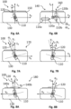
- Figs. 3A to 3E are schematic views of an electronics device 500 according to some embodiments.
- the electronics device 500 comprises at least one orientation sensor 520.
- the at least one orientation sensor 520 may comprise an angle sensor arranged between the at least one second device part 532 and the first device part 531.
- the angle sensor may be configured to generate angle sensor measurement data between the first device part 531 and the at least one second device part 532.
- the angle sensor may be arranged on or in the at least one hinge 533. Angle sensor measurement data may be indicative of a rotation and/or an orientation of the at least one second device part 532 relative to the first device part 531.
- the at least one orientation sensor 520 may comprise at least one magnetic object 521 arranged in the first device part 531 and one or more of the plurality of magnetometers 300 arranged in the at least one second device part 532.
- the at least one orientation sensor 520 may be configured to generate magnetic field measurement data associated with the at least one magnetic object 521.
- Magnetic field measurement data associated with the at least one magnetic object 521 may be indicative of a rotation and/or an orientation of the at least one second device part 532 relative to the first device part 531.
- the at least one orientation sensor 520 may comprise at least one accelerometer arranged in the at least one second device part 532 and/or the first device part 531. More specifically, the at least one orientation sensor 520 may be configured to generate accelerometer measurement data.
- the accelerometer may be configured to measure a physical acceleration experienced by a rotation and/or an orientation of the at least one second device part 532 relative to the first device part 531.
- an accelerometer may be arranged in the at least one second device part 532 and another accelerometer may be arranged in the first device part 531.
- the measurement data of the respective accelerometers may be compared to each other.
- the compared accelerometer measurement data may be indicative of a rotation and/or an orientation of the at least one second device part 532 relative to the first device part 531.
- the plurality of magnetometers 300 may be a first plurality of magnetometers 300a.
- the created magnetic field measurements (measured with the plurality of magnetometers 300) may be first magnetic field measurements.
- the electronics device 500 may comprise a second plurality of magnetometers 300b.
- the second plurality of magnetometers 300 may be arranged in the first device part 531.
- the at least one orientation sensor 520 may comprise the first plurality of magnetometers 300a and the second plurality of magnetometers 300b.
- the at least one orientation sensor 520 may be configured to generate first magnetic field measurement data associated with the at least one magnetic object 110 with the first plurality of magnetometers 300a, and second magnetic field measurement data associated with the at least one magnetic object 110 with the second plurality of magnetometers 300b.
- First magnetic field measurement data and second magnetic field measurement data may be evaluated and/or compared with respect to each other.
- the compared magnetic field measurement data may be indicative of a rotation and/or an orientation of the at least one second device part 532 relative to the first device part 531.
- the at least one orientation sensor 520 may comprise the plurality of magnetometers 310.
- the at least one orientation sensor 520 may be configured to generate magnetic field measurement data associated with the at least one magnetic object 110. More specifically, magnetic field measurement data associated with the at least one magnetic object 110 may be indicative of an interaction surface normal N3, particularly in an initial state of the at least one user-borne device 100. Based on the magnetic field measurement data indicative of the interaction surface normal N3, an orientation and/or a rotation of the at least one second device part 532 relative to the at least one first device part 531 may be determined.
- Fig. 11 schematically illustrates the steps of a computer-implemented method 600 for determining a user-borne device location according to aspects of the present disclosure.
- Fig. 12 schematically illustrates the steps of the computer-implemented method 600 in more detail.
- the computer-implemented method 600 comprises obtaining magnetic field measurements 610 associated with at least one magnetic object 110 with a plurality of magnetometers 300.
- the at least one magnetic object 110 is coupled to at least one user-borne device 100.
- the at least one user-borne device 100 is associated with an interaction reference coordinate system Xs, Ys, Zs.
- the computer-implemented method 600 comprises obtaining orientation data 620 from at least one orientation sensor 520, wherein the at least one orientation sensor 520 is arranged in an electronics device 500.
- the plurality of magnetometers 300 is arranged in the electronics device 500. Furthermore, the computer-implemented method 600 comprises determining an orientation and a position 630 of the plurality of magnetometers 300 relative to the interaction reference coordinate system Xs, Ys, Zs based on the obtained orientation data. In addition, the computer-implemented method 600 comprises determining a user-borne device location 640 (more specifically, of the at least one user-borne device 100) relative to the interaction reference coordinate system Xs, Ys, Zs based on the obtained magnetic field measurements and the determined orientation and position.
- the plurality of magnetometers 300 arranged in the electronics device 500 may be movable, more specifically rotatable, relative to the interaction reference coordinate system Xs, Ys, Zs, particularly to the interaction surface 210.
- the determination and/or tracking of the location of the at least one user-borne device 100 relative to the interaction reference coordinate system Xs, Ys, Zs can be enabled although the plurality of magnetometers may be moved (e.g., rotated) to different positions and/or orientations relative to the interaction reference coordinate system Xs, Ys, Zs, more specifically relative to the interaction surface 210.
- the determined orientation and position may include an inclination, an orthogonal orientation, a parallel orientation, a rotation and/or a position of the plurality of magnetometers 300 relative to the interaction reference coordinate system Xs, Ys, Zs.
- the plurality of magnetometers 300 may be arranged in a movable part (i.e., the at least one second device part 532) of the electronics device 500. Furthermore, the determination of the user-borne borne device location relative to the interaction reference coordinate system Xs, Ys, Zs may be automatically adapted even when the plurality of magnetometers 300 is rotated relative to the interaction reference coordinate system Xs, Ys, Zs, more specifically to the interaction surface 210.
- the location of a at least one user-borne device 100 can be determined and/or tracked with increased accuracy and/or reliability.
- a representation of the at least one user-borne device 100 as a virtual object on at least one output device 510 can be provided with increased accuracy and reliability.
- the order, in which the data or measurements as described above are obtained, may vary.
- the at least one user-borne device 100 may be operable on an interaction surface 210. More specifically, the vertical interaction reference axis Zs of the interaction reference coordinate system Xs, Ys, Zs may be orthogonal to the interaction surface 210. In embodiments, the first interaction reference axis Xs and the second interaction reference axis Ys may be defined on the interaction surface 210.
- the first device part 531 may comprise a top surface 534. In some embodiments, the interaction reference coordinate system Xs, Ys, Zs may be defined on the top surface 534. In some embodiments, the vertical interaction reference axis Zs may be orthogonal to the first device part 531, more specifically to the top surface 534.
- the plurality of magnetometers 300 may be configured to create a sensing volume M (as indicated, e.g., in Fig. 5 ).
- the interaction reference coordinate system Xs, Ys, Zs and/or the interaction surface 210 may be defined within the sensing volume M.
- the sensing volume M may have an ellipsoidal form.
- the plurality of magnetometers 300 may be associated with a magnetometer plane 310 as described above.
- the method 600 may comprise defining a measurement reference coordinate system Xm, Ym, Zm relative to the plurality of magnetometers 300 (see, e.g., Figs. 1 to 4 ).
- the measurement reference coordinate system Xm, Ym, Zm may be associated with a location of at least one magnetometer of the plurality of magnetometers 300 as mentioned above.
- the at least one user-borne device 100 may be electrically and/or electronically passive. More specifically, electrically passive means that the at least one user-borne device 100 may not comprise a power source (e.g., batteries) and/or means to receive power (e.g., wireless power transmission via an inductive coil) for powering a feature (e.g., an electronic feature) of the at least one user-borne device 100. Electronically passive means that no computation or processing occurs (or happens) on the at least one user-borne device 100.
- a power source e.g., batteries
- power e.g., wireless power transmission via an inductive coil
- Electronically passive means that no computation or processing occurs (or happens) on the at least one user-borne device 100.
- the term "at least one magnetic object” may refer to an object which may comprise components made of magnetic material, i.e., a material that has magnetic properties measurable by the plurality of magnetometers 300.
- the at least one user-borne device 100 and/or the at least one magnetic object 210 may be mobile, i.e., freely movable with respect to the measurement reference coordinate system Xm, Ym, Zm.
- the location of the at least one user-borne device 100 within the sensing volume M and/or relative to the interaction reference coordinate system Xs, Ys, Zs may be manipulated by a user within the sensing volume M.
- the at least one magnetic object 110 may be a permanent magnet. In embodiments, the at least one magnetic object 110 may be configured to generate a non-zero magnetic field. It may comprise a paramagnetic or diamagnetic material. In embodiments, the at least one magnetic object 110 may comprise a ferromagnetic material or a ferrimagnetic material.
- the method 600 may further comprise defining a user-borne device coordinate system (see, e.g., Figs. 6A to 8B ).
- the device coordinate system may comprise a first device axis x d , a second device axis y d orthogonal to the first device axis x d , and a vertical device axis z d .
- the vertical device axis z d may be orthogonal to a device contact surface or point 130 and/or orthogonal to a plane defined by the first device axis x d and the second device axis y d .
- the device contact surface or point 130 may be the part of the at least one user-borne device 100 which, during a user operation, may be in contact with the interaction surface 210.
- the at least one user-borne device 100 may comprise a contact surface 130 contacting an interaction surface 210.
- the at least one user-borne device 100 may comprise a contact point 130 (e.g., a stylus or other writing device comprising a writing tip which contacts an interaction surface 210 during a writing operation).
- the at least one user-borne device 100 may be operated within a sensing volume M but not on an interaction surface 210.
- the at least one user-borne device 100 may be used, e.g., as a pointer.
- the pointer may be operable relative to an interaction surface 210 (e.g., pointing on a portion of the interaction surface 210), but being at a distance to the interactions surface 210 (i.e., having no contact with the interaction surface 210).
- the device coordinate system may be defined within a geometric center of the at least one user-borne device 100.
- the determined orientation may comprise a rotation and/or an inclination of the plurality of magnetometers 300 relative to the interaction reference coordinate system Xs, Ys, Zs. More specifically, the determined orientation and position may include an inclination, an orthogonal orientation, a parallel orientation, a rotation and/or a position of the plurality of magnetometers 300 relative to the interaction reference coordinate system Xs, Ys, Zs. More specifically, in case the interaction reference coordinate system Xs, Ys, Zs is defined on the interaction surface 210, the determined orientation and position may comprise a rotation and/or an inclination of the plurality of magnetometers 300 relative to the interaction surface 210.
- the rotation may be defined by at least one rotation axis R defined relative to the plurality of magnetometers 300, more specifically the measurement reference coordinate system Xm, Ym, Zm, and defined relative to the interaction reference coordinate system Xs, Ys, Zs.
- Determining an orientation and a position 630 may comprise determining an orientation and a position of the measurement reference coordinate system Xm, Ym, Zm relative to the interaction reference coordinate system Xs, Ys, Zs based on the obtained orientation data. More specifically, determining an orientation and a position 630 may comprise determining an orientation and a position of the second device part 532 relative to the first device part 531.
- determining an orientation and a position 630 may comprise detecting a rotation 631 of the plurality of magnetometers 300, more specifically of the measurement reference coordinate system Xm, Ym, Zm, relative to the interaction reference coordinate system Xs, Ys, Zs, particularly relative to the first device part 532, based on the obtained orientation data. Additionally or alternatively, determining an orientation and a position 630 may comprise determining 632 an orientation angle ⁇ between the plurality of magnetometers 300, more specifically between the measurement reference coordinate system Xm, Ym, Zm, and the interaction reference coordinate system Xs, Ys, Zs, particularly the first device part 531, based on the obtained orientation data.
- the rotation of the measurement reference coordinate system Xm, Ym, Zm to the interaction reference coordinate system Xs, Ys, Zs may be detected.
- the orientation angle ⁇ between the measurement reference coordinate system Xm, Ym, Zm and the interaction reference coordinate system Xs, Ys, Zs may be determined.
- a rotation of the at least one second device part relative to the first device part 531 may be detected.
- an orientation angle ⁇ between the at least one second device part 532 and the first device part 531 may be determined.
- the detected orientation angle ⁇ may be between 0° and 360°.
- the detected orientation angle ⁇ may be 0°, 90°, 180° or 270°. In this case, the orientation angle ⁇ may depend on the position of the data and/or power transmission port 535 between the first device part 531 and the at least one second device part 532.
- determining an orientation and a position 630 may comprise determining 633 a first normal vector N1 orthogonal to the interaction surface 210 based on the determined orientation angle ⁇ . More specifically, the first normal vector N1 may be parallel to the vertical interaction reference axis Zs.
- the first device part 531 may comprise a top surface 534 and the first normal vector N1 may be defined on the top surface 534. Determining 633 a first normal vector N1 orthogonal to the interaction surface 210 may comprise defining a second normal vector N2 associated with the at least one second device part 532.
- the second normal vector N2 may be substantially parallel to the vertical measurement reference axis Zm of the measurement reference coordinate system Xm, Ym, Zm and/or to a side surface of the at least one second device part 532.
- Determining 633 a first normal vector N1 orthogonal to the interaction surface 210 may comprise obtaining position data of a rotation axis R between the measurement reference coordinate system Xm, Ym, Zm, more specifically the at least one second device part 532, and the interaction reference coordinate system Xs, Ys, Zs, more specifically the first device part 531.
- Determining 633 a first normal vector N1 orthogonal to the interaction surface 210 may comprise calculating the first normal vector N1 based on the obtained position data and the determined orientation angle ⁇ .
- the first normal vector N1 may be calculated by applying Rodrigues' rotation formula. Calculating the first normal vector N1 may be based on the defined second normal vector N2, the determined orientation angle ⁇ , and the obtained rotation axis R position data. As shown in Fig. 3A , the second normal vector N2 may extend from a second position point P2 defined on the at least one second device part 532, which may be at a second distance l2 to the at least one rotation axis R. The second distance l2 and/or the second position point P2 may be obtained from a data base.
- the first normal vector N1 may extend from a first position point P1 (e.g., on a top surface 534 of the first device part 531), which may be at a first distance l1 to the at least one rotation axis R.
- the first distance l1, the first position point P1, and the first normal vector N1 may be determined based on applying Rodrigues' rotation formula.
- the at least one orientation sensor 520 may comprise an angle sensor arranged between the at least one second device part 532 and the first device part 531.
- the obtained orientation data may comprise angle sensor measurement data.
- Angle sensor measurement data may be indicative of a rotation and/or an orientation of the at least one second device part 532 relative to the first device part 531. Based on angle sensor measurement data, the rotation may be detected and/or the orientation angle ⁇ may be determined.
- the at least one orientation sensor 520 may comprise at least one magnetic object 521 arranged in the first device part 531 and one or more of the plurality of magnetometers 300 arranged in the at least one second device part 532. More specifically, the at least one magnetic object 110 coupled to the at least one user-borne device 100 may be at least one first magnetic object 110. The at least one magnetic object 521 arranged in (and/or coupled to) the first device part 531 may be at least one second magnetic object 521.
- the determination of the absolute magnetic object location 641 as described below for the at least one magnetic object 110 coupled to the at least one user-borne device 100 can be applied analogously for determining an absolute magnetic object location of the at least one magnetic object 521 arranged in (and/or coupled to) the first device part 531.
- the absolute magnetic object location of the at least one magnetic object 521 may be indicative of an absolute magnetic object position and/or an absolute magnetic object orientation of the at least one magnetic object 521 relative to the measurement reference coordinate system Xm, Ym, Zm.
- the obtained orientation data may comprise magnetic field measurement data associated with the at least one magnetic object 521 arranged in the first device part 531 and measured with the one or more magnetometers of the plurality of magnetometers 300.
- the magnetic field of the at least one magnetic object 521 may be measured and magnetic field measurement data may be used to determine the orientation and position.
- Magnetic field measurement data associated with the at least one magnetic object 521 may be indicative of a rotation and/or an orientation of the at least one second device part 532 relative to the first device part 531.
- the rotation may be detected and/or the orientation angle ⁇ may be determined.
- the at least one orientation sensor 520 may comprise at least one accelerometer arranged in the at least one second device part 532 and/or the first device part 531.
- the obtained orientation data may comprise accelerometer measurement data as described above. Accelerometer measurement data may be indicative of a rotation and/or an orientation of the at least one second device part 532 relative to the first device part 531.
- an accelerometer may be arranged in the at least one second device part 532 and another accelerometer may be arranged in the first device part 531. The accelerometer measurement data of the respective accelerometers may be compared to each other.
- the (compared) accelerometer measurement data may be indicative of a rotation and/or an orientation of the at least one second device part 532 relative to the first device part 531. Based on the accelerometer measurement data, the rotation may be detected and/or the orientation angle ⁇ may be determined.
- the plurality of magnetometers 300 may be a first plurality of magnetometers 300a.
- the obtained magnetic field measurements (measured with the plurality of magnetometers 300) may be first magnetic field measurements.
- the electronics device 500 may comprise a second plurality of magnetometers 300b.
- the second plurality of magnetometers 300 may be arranged in the first device part 531.
- the computer-implemented method 600 may further comprise obtaining second magnetic field measurements associated with the at least one magnetic object 110 with the second plurality of magnetometers 300b.
- the at least one orientation sensor 520 may comprise the first plurality of magnetometers 300a and the second plurality of magnetometers 300b.
- the obtained orientation data may comprise first magnetic field measurement data associated with the at least one magnetic object 110 from the first plurality of magnetometers 300a and second magnetic field measurement data associated with the at least one magnetic object 110 from the second plurality of magnetometers 300b. More specifically, first magnetic field measurement data and second magnetic field measurement data may be evaluated and/or compared to each other. The (evaluated and/or compared) first magnetic field measurement data and/or second magnetic field measurement data associated with the at least one magnetic object 100 may be indicative of a rotation and/or an orientation of the at least one second device part 532 relative to the first device part 531. Based on first magnetic field measurement data and/or second magnetic field measurement data associated with the at least one magnetic object 100, the rotation may be detected and/or the orientation angle ⁇ may be determined.
- detecting a rotation 631 and/or determining 632 an orientation angle ⁇ may comprise determining an absolute magnetic object location indicative of an absolute magnetic object position and/or an absolute magnetic object orientation of the at least one magnetic object 110 relative to the measurement reference coordinate system Xm, Ym, Zm and based on the obtained orientation data.
- a first absolute magnetic object location of the at least one magnetic object 110 may be determined relative to the first plurality of magnetometers 300b, and a second magnetic object location of the at least one magnetic object 110 may be determined relative to the second plurality of magnetometers 300b. Determining an orientation and a position 630 may be based on the first and second magnetic object locations.
- the electronics device 500 may comprise (or may be) a board, a foldable smartphone or a foldable tablet.
- the board may be e.g., a whiteboard, a blackboard, a digital board (on which a stylus may be operated), a drawing and/or writing board, or a presentation board.
- the first device part 531 may be connected to a wall or a stand, and the at least one second device part 532 may be rotatably coupled to the first device part 531.
- the at least one orientation sensor 520 may comprise the plurality of magnetometers 310.
- the obtained orientation data may comprise magnetic field measurement data associated with the at least one magnetic object 110.
- Magnetic field measurement data associated with the at least one magnetic object 110 may be indicative of an interaction surface normal N3, more specifically in an initial state of the at least one user-borne device 100 (the initial state will be described in detail below).
- the at least one magnetic object 110 may be arranged in the at least one user-borne device 100 parallel to the vertical device axis z d .
- the magnetic object moment vector 120 may be arranged orthogonal with respect to the interaction surface 210 and/or parallel to the vertical device axis z d in the initial state of the at least one user-borne device 100. This may be the case when the at least one user-borne device 100 is operated on the interaction surface 210 and comprises a contact surface 130 relative to the interaction surface 210.
- Detecting a rotation 631 and/or determining 632 an orientation angle ⁇ may comprise determining an absolute magnetic object location indicative of an absolute magnetic object position and/or an absolute magnetic object orientation of the at least one magnetic object 110 relative to the plurality of magnetometers 300, more specifically to the measurement reference coordinate system Xm, Ym, Zm, and based on the obtained orientation data.
- the absolute magnetic object location may include a magnetic object moment vector 120 and/or a magnetic object position vector associated with the at least one magnetic object 110. Based on the magnetic field measurement data associated with the at least one magnetic object 110, more specifically the magnetic object moment vector 120 and/or a magnetic object position vector associated with the at least one magnetic object 110, the rotation may be detected and/or the orientation angle ⁇ may be determined.
- the computer-implemented method 600 may further comprise, in response to detecting a rotation 633, determining at least one rotation trigger event 634 associated with the detected rotation.
- the electronics device 500 may comprise a sleep mode and an active mode. Determining at least one rotation trigger event 634 may comprise determining a sleep mode event in response to detecting a rotation 633 in a first direction (e.g., a clockwise rotation about the rotation axis R). The sleep mode event may cause a transition of the electronics device 500 from an active mode to the sleep mode.
- determining at least one rotation trigger event 634 may comprise determining an active mode event in response to detecting a rotation 633 in a second direction (e.g., a counter-clockwise rotation about the rotation axis R).
- the active mode event may cause a transition of the electronics device 500 from the sleep mode to the active mode.
- the electronics device 500 may comprise a specific threshold orientation angle associated with the orientation of the at least one second device part 532 relative to the first device part 531 at which the respective mode may be activated.
- the sleep mode may be a power save mode of the electronics device 500.
- the electronics device 500 may comprise (or may be) a notebook, a laptop, a foldable smartphone, a foldable tablet, and/or an electronic device sleeve.
- determining an orientation and a position 630 may comprise determining an interaction surface location 650.
- the interaction surface location may be indicative of an interaction surface position, an interaction surface orientation and/or an interaction surface distance c relative to the electronics device 500, more specifically to the first device part 531.
- the interaction surface distance c may be measured between the interaction surface 210 and the top surface 534.
- the interaction surface location 650 may be defined based on a first set of geometric parameters associated with the interaction surface 210, more specifically wherein the first set of geometric parameters may be indicative of a geometry of the interaction surface 210.
- the first set of geometric parameters may comprise predefined geometric parameters associated with the interaction surface 210.
- the first set of parameters may be obtained from a database.
- Determining an interaction surface location 650 may comprise deriving a first interaction surface configuration 210a being indicative of a location of the interaction surface 210 substantially parallel to and on the electronics device 500, more specifically on the top surface 534 of the first device part 531. In some embodiments, determining an interaction surface location 650 may comprise deriving a second interaction surface configuration 210b being indicative of a location of the interaction surface 210 substantially parallel to and distanced to the electronics device 500, more specifically to the top surface 534 of the first device part 531. The distance may be interaction surface distance c as described above.
- the location of the interaction surface 210 relative to the first device part 531 may be known and the orientation of the first device part 531 relative to the at least one second device part 532 (in which the plurality of magnetometers 300 is arranged) may be determined, it is possible to determine the position and orientation of the plurality of magnetometers 300 relative to the interaction reference coordinate system Xs, Ys, Zs, more specifically to the interaction surface 210.
- determining a user-borne device location 640 may comprise determining an absolute magnetic object location 641.
- the absolute magnetic object location may be indicative of an absolute magnetic object position and/or an absolute magnetic object orientation of the at least one magnetic object 110 relative to the plurality of magnetometers 300, more specifically to the measurement reference coordinate system Xm, Ym, Zm. More specifically, the absolute magnetic object location may be determined based on the obtained magnetic field measurements.
- the obtained magnetic field measurements may be indicative of a magnetic field associated with the at least one magnetic object 110.
- determining an absolute magnetic object location 641 may comprise generating magnetic field measurement data 642 based on the obtained magnetic field measurements.
- the magnetic field measurement data may be indicative of a magnetic field position, a magnetic field orientation and/or a magnetic field strength relative to the measurement reference coordinate system Xm, Ym, Zm.
- Determining an absolute magnetic object location 641 may further comprise processing magnetic field measurement data 643 to relate magnetic field measurement data to an absolute magnetic object location (i.e., the absolute magnetic object location as described above).
- the absolute magnetic object location may include a magnetic object moment vector 120 and/or a magnetic object position vector associated with the at least one magnetic object 110.
- the magnetic moment vector 120 may be indicative of a magnetic object orientation and/or a magnetic field strength of the least one magnetic object 110 with respect to the measurement reference coordinate system Xm, Ym, Zm.
- the magnetic object position vector may be indicative of a magnetic object position with respect to the measurement reference coordinate system Xm, Ym, Zm.
- the absolute magnetic object orientation may be defined by a first set of magnetic object inclination angles ⁇ 1, ⁇ 2, ⁇ 3 measured between the measurement reference coordinate system Xm, Ym, Zm (and/or in some embodiments the magnetometer plane 310) and a projection of the magnetic moment vector 120 on (or relative to) the measurement reference coordinate system Xm, Ym, Zm (and/or in some embodiments the magnetometer plane 310).
- the absolute magnetic object orientation may be defined by a first set of cartesian coordinates defined within the measurement reference coordinate system Xm, Ym, Zm.
- the first set of magnetic object orientation angles ⁇ 1 , ⁇ 2 , ⁇ 3 may be measured relative to the measurement reference coordinate axes Xm, Ym, Zm, more specifically between or a projection of the magnetic object moment vector 120 and the respective axes Xm, Ym, Zm of the measurement reference coordinate system Xm, Ym, Zm.
- the first magnetic object orientation angle ⁇ 1 may be defined between the first measurement reference axis Xm and the projection of the magnetic object moment vector 120, more specifically in the Xm-Zm-plane.
- the magnetic object moment vector 120 and/or the magnetic object position vector may be determined based on the obtained magnetic field measurements.
- the magnetic object moment vector 120 and/or the magnetic object position vector may be determined based on an implementation of a mathematical model associating each measurement of a magnetometer of the plurality of magnetometers 300 with a location of the at least one magnetic object 110 in the measurement reference coordinate system Xm, Ym, Zm.
- the model may be typically constructed from physical equations of electromagnetism, more specifically equations of magnetostatics. To establish this model, the at least one magnetic object 110 may be approximated by a magnetic dipole.
- Each magnetometer of the plurality of magnetometers 300 may be a vector magnetometer and may be configured to measure the magnetic field in one, two or three dimensions as described above.
- determining a user-borne device location 640 may comprise determining a relative magnetic object location 644 indicative of a relative magnetic object position and/or a relative magnetic object orientation of the at least one magnetic object 110 relative to the at least one user-borne device 110, more specifically to the device coordinate system.
- the relative magnetic object orientation may be defined based on a second set of magnetic object inclination angles ⁇ 1, ⁇ 2, ⁇ 3. More specifically, the second set of inclination angles ⁇ 1, ⁇ 2, ⁇ 3 may be measured between the magnetic object moment vector 120 and the respective axes of the device coordinate system (see, e.g., Figs. 6A, 7A and 7B ).
- Determining a relative magnetic object location 644 may be based on the absolute magnetic object location as described above and a second set of geometric parameters.
- the second set of geometric parameters may comprise predefined geometric parameters indicative of a geometric position and/or a geometric orientation of the at least one magnetic object 100 relative to the at least one user-borne device 100, more specifically in an initial state of the at least one user-borne device 100 (the initial state will be described in more detail below).
- the second set of geometric parameters may be obtained from a database. In other words, based on the determined absolute location of the at least one magnetic object 110 and the knowledge of the arrangement of the at least one magnetic object 110 in the at least one user-borne device 100 (more specifically relative to the device coordinate system), the user-borne device location may be known.
- determining a relative magnetic object location 644 may comprise detecting a position and/or orientation deviation 645 of the relative magnetic object position and/or a relative magnetic object orientation caused by a translation and/or a rotation of the at least one magnetic object 110 relative to the at least one user-borne device 100, more specifically wherein the at least one user-borne device 100 may be in an actuated state.
- the device coordinate system may be defined in a geometric center of the user-borne device 100.
- the at least one magnetic object 110 In the initial state, the at least one magnetic object 110 may be in an initial location, e.g., inclined and/or distanced with respect to the device coordinate system and/or to the geometric center of the at least one user-borne device 100.
- the at least one user-borne device 100 may be in an actuated state, when the at least one magnetic object 110 is in an actuated location relative to the initial location (and/or relative to the at least one user-borne device 100 and/or to the housing 150).
- the at least one user-borne device 100 may be in an actuated state, when the at least one magnetic object 110 is rotated and/or translated relative to the at least one user-borne device 100, more specifically from the initial location.
- the magnetic object orientation and/or the magnetic object position of the at least one magnetic object 110 relative to the device coordinate system may be different compared to the initial state. As indicated in Fig.
- the method 600 may comprise, in response to detecting the position and/or orientation deviation, determining at least one interaction trigger event 646 associated with the position and/or the orientation deviation. Based on the detected specific translation and/or rotation, the method 600 may comprise transforming the detected position and/or orientation deviation to an interaction trigger event associated with the respective translation and/or rotation.
- the method 600 may obtain data from a database.
- the database may comprise data associating the at least one interaction trigger event with a specific translation and/or rotation of the at least one magnetic object 110 from the initial location to the actuated location. Examples of the at least one interaction trigger event will be described in detail below.
- the determined user-borne device location may comprise a user-borne device position and/or a user-borne device orientation of the at least one user-borne device 100 relative to the interaction reference coordinate system Xs, Ys, Zs, more specifically relative to the interaction surface 210.
- determining an absolute magnetic object location 641 may comprise determining, based on the magnetic object moment vector 120 and/or the magnetic object position vector, whether the at least one magnetic object 110 is located on a side of the measurement reference coordinate system Xm, Ym, Zm facing towards a user U during operation of the at least one user-borne device 100 and/or the electronics device 500, or, on a side of the measurement reference coordinate system Xm, Ym, Zm facing away from a user U during operation of the at least one user-borne device 100 and/or the electronics device 500 (see, e.g., Fig. 4 ). More specifically this may be defined relative to the magnetometer plane 310 and/or the second device part 532.
- Determining an absolute magnetic object location 641 may comprise determining, based on the magnetic object moment vector 120 and/or the magnetic object position vector, whether the at least one magnetic object 110 is located on a side of the magnetometer plane 310 facing towards a user U during operation of the at least one user-borne device 100 and/or the electronics device 500, or, on a side of the magnetometer plane 310 facing away from a user U during operation of the at least one user-borne device 100 and/or the electronics device 500. In other words, based on these features, it may be determined whether the at least one user-borne device 100 is operated in front or behind the second device part 532, more specifically in front or behind the magnetometer plane 310.
- determining a user-borne device location 640 may comprise deriving the magnetic object moment vector 120 and/or the magnetic object position vector from the absolute magnetic object location. Determining a user-borne device location 640 may further comprise deriving the determined interaction surface location relative to the electronics device 500. Determining a user-borne device location 640 may further comprise determining a first virtual intersection point of a projection of the magnetic object moment vector 120 and the interaction surface 210.
- determining a user-borne device location 640 may comprise assuming a user-borne device contact 646 between the at least one user-borne device 100 and the interaction surface 210. More specifically, assuming a user-borne device contact 646 may comprise determining a second virtual intersection point between the vertical device axis z d and the interaction surface 210. Assuming a user-borne device contact 646 between the at least one user-borne device 100 and the interaction surface 210 may be based on the determined interaction surface location and the determined relative magnetic object location. Furthermore, assuming a user-borne device contact 646 between the at least one user-borne device 100 and the interaction surface 210 may be based on the determined absolute magnetic object location and/or the determined position and orientation.
- the computer-implemented method may further comprise representing 660 the at least one user-borne device 100 as a virtual object on the at least one output device 510 (and/or the at least one additional output device) based on the determined user-borne device location. More specifically, a movement of the virtual object on the at least one output device 510 may be based on a virtual reproduction of the location of the at least one user-borne device 100 relative to the interaction reference coordinate system Xs, Ys, Zs, more specifically relative to the interaction surface 210. A manipulation of the user-borne device location during a user operation may thus be represented as a virtual object on the at least one output device 510 (and/or the at least one additional output device).
- the at least one user-borne device 100 may be visually reproduced as a virtual object.
- the at least one output device 510 (and/or the at least one additional output device) may be configured to visually reproduce the virtual object.
- Representing 660 the at least one user-borne device 100 may comprise reproducing a movement of the at least one user-borne device 100 within the sensing volume M as a movement of the virtual object on the at least one output device 510.
- the movement of the at least one user-borne device 100 within the sensing volume M may be caused by a manipulation of the user-borne device 100 during a user operation (i.e., by a user manipulating the location of the at least one user-borne device 100).
- the movement of the user-borne location may be determined and reproduced as a movement of the virtual object on the at least one output device 510 (and/or the at least one additional output device).
- the visual reproduction may be a motion of a cursor on the at least one output device 510 (and/or the at least one additional output device).
- the visual reproduction may not be identical to the design of the at least one user-borne device 100 but may be any icon (e.g., an arrow, a picture).
- the visual reproduction may be a drawing or letters.
- the visual reproduction may be a color change and/or a brightness change of the at least one output device 510 (e.g., the at least one output device 510 may become brighter or darker).
- the at least one output device 510 (and/or the at least one additional output device) may be a visual screen or a display. In some embodiments, the at least one output device 510 (and/or the at least one additional output device) may be a light indicator device or an audio device.
- the computer-implemented method 600 may further comprise initializing the plurality of magnetometers 300 and the at least one user-borne device 100, more specifically when a user starts a user operation.
- the at least one user-borne device 100 may be tracked over a time period comprising multiple time samples.
- the computer-implemented method 600 may comprise determining the user-borne device location 640, and may store the determined locations (or interactions) for each time sample.
- the computer-implemented method 600 may further comprise applying a filter for filtering the determined user-borne device location.
- a filter for filtering the determined user-borne device location.
- Magnetic and electronic noise, as well as environmental variations may lead to non-smooth location determinations over time.
- a smooth location trajectory of the at least one user-borne device 100 relative to the measurement reference coordinate system Xm, Ym, Zm and/or to the interaction reference coordinate system Xs, Ys, Zs may be achieved.
- the filter may be a low-pass filter or a Kalman filter, more specifically an extended Kalman filter or an unscented Kalman filter.
- the filter may use the magnetic field measurements of the plurality of magnetometers 300 as an input and may implement the mathematical model as described above to approximate the at least one magnetic object 110 by a magnetic dipole.
- the above-described computer-implemented method 600 can comprise or be executable via a computer or a network of computers, the computer or network of computers comprising at least one processing unit (e.g., a processor) and at least one data storage (i.e., memory).
- the described procedural logic may be held in the form of executable code in at least one data storage and executed by the at least one processing unit.
- the systems and subsystems may send data to the at least one processing unit and, in examples, they may also receive instructions from the at least one processing unit.
- the processing unit may thereby direct user-initiated and/or automatically generated queries to the system 10 and/or the electronics device 500.
- the system 10 and/or the electronics device 500 is not limited to a particular hardware environment.
- distributed devices coupled via a network may perform the techniques described herein.
- the disclosure also includes electrical signals and computer-readable media defining instructions that, when executed by a processing unit, implement the techniques described herein.
- the system 10 and/or the electronics device 500 may comprise at least one database.
- the system 10 and/or the electronics device 500 may access a database in a cloud (via a communication interface).
- the system 10 and/or the electronics device 500 may comprise a (at least one) communication interface to couple to plurality of magnetometers, the processing unit and/or the database.
- the communication interface may comprise one or more of a network, internet, a local area network, a wireless local area network, a broadband cellular network, and/or a wired network.
- the system 10 and/or the electronics device 500 may couple to one or more features via a server hosted in a cloud.
- a computer system may be configured to execute the computer-implemented method 600 as described above.
- a computer program may be configured to execute the computer-implemented method 600 as described above.
- a computer-readable medium or signal storing the computer program may be provided.
- the system 10 and/or the electronics device may be configured to track a movement of the at least one magnetic object 110 and/or the at least one user-borne device 100 in at least five degrees of freedom.
- the at least five degrees of freedom may include a translation of the at least one magnetic object 110 along the first measurement reference axis Xm, the second measurement reference axis Ym and the vertical measurement reference axis Zm, a first rotation about a first rotation axis, and a second rotation about a second rotation axis.
- the system 10 and/or the electronics device 500 may be configured to assume a contact between the user-borne device 100 and the interaction surface 210.
- the system 10 and/or the electronics device 500 may be configured to track a movement of the at least one user-borne device 100 within the sensing volume M and/or relative to the interaction surface 210 over a time period. More specifically the system 10 may be configured to determine a trajectory of the user-borne device 100 within the sensing volume M and/or relative to the interaction reference coordinate system Xs, Ys, Zs, more specifically the interaction surface 210. As already mentioned above, the at least one user-borne device 100 may be tracked over a time period comprising multiple time samples. At each time sample, the location of the at least one user-borne device 100 within the sensing volume M and/or relative to the interaction reference coordinate system Xs, Ys, Zs may be determined.
- the at least one user-borne device 100 may be a computer mouse.
- the at least one user-borne device 100 may be moved on the interaction surface 210 from a position x d , y d , to a position dx d , dy d .
- the system 10 and/or the electronics device 500 may be configured to track this movement based on determining the user-borne device location.
- the electronics device 500 may comprise a user interface configured to interact with a user U and/or receive a user input.
- the plurality of magnetometers 300 may be configured to receive data from and/or transmit data to the processing unit 400 and/or the external processing unit.
- the system 10 and/or the electronics device 500 may comprise a data storage connected to the processing unit 400.
- the data storage may comprise a primary data storage, e.g., a RAM, and a secondary data storage.
- the data storage may be integrated in and/or connected to the electronics device 500.
- the system 10 may comprise an interaction support 200 having an interaction support surface 230.
- the interaction surface 210 may be at least a partial surface of the interaction support surface 230.
- the interaction support 200 may not comprise ferromagnetic properties, e.g., ferromagnetic particles.
- the interaction support 200 may be a furniture (e.g., a table), an electronics device 500 as described above (e.g., a notebook, a laptop or a tablet), a screen, a wall, or a mouse pad.
- the interaction surface 210 may be defined based on the first set of geometric parameters associated with the interaction support 200. More specifically, the type of interaction support 200 may be known, e.g., a notebook or mouse pad.
- Such an interaction support 200 may be defined by the first set of geometric parameters as described above.
- a partial surface of the interaction support surface 230 may be used as interaction surface 210.
- the plurality of magnetometers 300 may be electrically (e.g., via wires or a data bus) or wirelessly connected to the processing unit 400, the external processing unit and/or to the electronics device 500.
- the at least one user-borne device 100 may comprise a housing 150.
- the at least one magnetic object 110 may be arranged in the housing 150.
- the at least one magnetic object 110 may be coupled to the housing 150.
- the relative magnetic object orientation relative to the at least one user-borne device 100 may be defined based on the second set of inclination angles ⁇ 1 , ⁇ 2 , ⁇ 3 as described above. More specifically, the second set of inclination angles ⁇ 1 , ⁇ 2 , ⁇ 3 may be measured between the magnetic moment vector 120 and the respective axes of the device coordinate system. In an example as shown in Figs.
- ⁇ 1 may be measured between the vertical device axis z d and the magnetic moment vector 120.
- the magnetic moment vector 120 may be inclined with respect to the vertical device axis z d .
- the magnetic moment vector 120 may extend substantially parallel to the vertical device axis z d .
- the at least one magnetic object 110 in the initial state of the at least one user-borne device 100, may be arranged in the housing 150 such that the vertical device axis z d extends through the magnetic moment vector 120.
- the at least one magnetic object 110 in the initial state of the at least one user-borne device 100, may be arranged in the housing 150 such that the magnetic moment vector 120 is parallel but distanced to the vertical device axis z d (see, e.g., Fig. 6B ).
- the at least one magnetic object 110 may be movable relative to the at least one user-borne device 100, more specifically wherein the at least one magnetic object 110 may be rotatable and/or translatable relative to the at least one user-borne device 100 (and/or to the housing 150).
- the at least one user-borne device 100 may be in an initial state, when the at least one magnetic object 110 is in an initial location relative to the at least one user-borne device 100, more specifically to the housing 150.
- the user-borne device 100 may be in an initial state, when the at least one magnetic object 110 is not rotated and/or translated relative to the at least one user-borne device 100.
- the device coordinate system may be defined in a geometric center of the at least one user-borne device 100.
- the at least one magnetic object 110 may be inclined and/or distanced with respect to the device coordinate system and/or to the geometric center of the at least one user-borne device 100.
- the user-borne device 100 may be in an actuated state, when the at least one magnetic object 110 is in an actuated location relative to the initial location (and/or relative to the at least one user-borne device 100 and/or to the housing 150).
- the at least one user-borne device 100 may be in an actuated state, when the at least one magnetic object 110 is rotated and/or translated relative to the at least one user-borne device 100, more specifically from the initial location.
- the magnetic object orientation and/or the magnetic object position of the at least one magnetic object 110 relative to the device coordinate system may be different compared to the initial state.
- the at least one user-borne device 100 may comprise at least two magnetic objects 110a, 110b having different relative orientations to each other.
- the system 10 and/or the electronics device 500 may be configured to determine relative magnetic object orientations of each of the at least two magnetic objects 110a, 110b. More specifically, the system 10 and/or the electronics device 500 may be configured to determine a magnetic moment vector 120a, 120b of each of the at least two magnetic objects 110a, 110b.
- the system 10 and/or the electronics device 500 may be configured to determine a magnetic object position, a magnetic object orientation and/or a magnetic object distance of each of the at least two magnetic objects 110a, 110b relative to the reference coordinate system XYZ, more specifically the magnetometer plane 310, and/or to the interaction surface 210.
- a first magnetic object 110a may comprise a first magnetic moment vector 120a.
- a second magnetic object 110b may comprise a second magnetic moment vector 120b.
- the first magnetic moment vector 120a may be inclined with respect to the second magnetic moment vector 120b.
- the first magnetic moment vector 120a may be substantially orthogonal to the second magnetic moment vector 120b.
- the first magnetic object 110a may be fixedly coupled to the at least one user-borne device 100. This means that the first magnetic object 110a may not be rotatable and/or translatable with respect to the at least one user-borne device 100.
- the first magnetic object 110b may be arranged in the housing 150.
- the second magnetic object 110b may be rotatable and/or translatable relative to the at least one user-borne device 100 and/or to the first magnetic object 110a.
- the system 10 and/or the electronics device 500 may be configured to track a movement of the at least two magnetic objects 110a, 110b in at least six degrees of freedom.
- the at least one user-borne device 100 comprising at least two magnetic objects 110a, 110b allows to determine a relative position and/or a relative orientation deviation of the two at least two magnetic objects 110a, 110b with respect to each other.
- Fig. 6B illustrates a translation 160 of the at least one magnetic object relative to the device coordinate system from an initial location to an actuated location.
- a second magnetic object 110b may arranged in the housing 150, which is translated from an initial location to an actuated location.
- the second magnetic object 110b is translated in the direction of the first device axis x d and in the direction of the vertical device axis z d .
- Such a translation 160 from the initial location to the actuated location may be described by dx m and dz m as indicated in Fig. 6B .
- the features described above may analogously apply for the at least one magnetic object 110.
- the at least one magnetic object 110 may be fixedly arranged in the housing 150. In this case, the at least one magnetic object 110 may not be translatable 160 and/or rotatable with respect to the at least one user-borne device 100 (and/or the housing 150).
- a rotation of the at least one magnetic object 110 relative to the at least one user-borne device 100 and/or to the housing 150 is shown.
- the at least one magnetic object 110 may be rotated by a first rotation 170 from the initial location to an actuated location about the second device axis y d .
- the at least one magnetic object 110 in the initial state, is inclined by angle ⁇ 1 measured between the magnetic moment vector 120 and the vertical device axis z d .
- the at least one magnetic object 110 in its initial location, the at least one magnetic object 110 may be arranged inclined with respect to the vertical device axis z d .
- the first rotation 170 may be defined by a first rotation angle ⁇ 1 measured between the initial location (i.e., an initial position and/or orientation of the magnetic moment vector in the initial state) and the magnetic moment vector 120.
- the first rotation angle ⁇ 1 may comprise a positive value.
- the first rotation angle ⁇ 1 may comprise a negative value.
- the at least one magnetic object 110 in its initial location and/or state, may comprise a magnetic moment vector 120 which is parallel to the vertical device axis z d .
- an inclination angle ⁇ 2 about the first device axis x d may be zero.
- the at least one magnetic object 110 may be rotated by a second rotation 180 from the initial location to an actuated location about the first device axis x d .
- Such a second rotation 180 may be defined by a second rotation angle ⁇ 2 measured between the vertical device axis z d and the magnetic moment vector 120.
- the second rotation angle ⁇ 2 may comprise a positive value
- the second rotation angle ⁇ 2 may comprise a negative value.
- a combination of a rotation 170, 180 and/or a translation 160 as described above is also possible.
- the translation 160 of the at least one magnetic object 110 from the initial location to the actuated location is only shown in the example of Fig. 6B in the direction of the first device axis x d and the vertical device axis z d .
- any combination of translations with respect to the device axes x d , y d , z d may be possible, more specifically along the first device axis x d , the second device axis y d and/or the vertical device axis z d .
- the system 10 and/or the electronics device 500 may be configured to detect the translation 160 and/or rotation 170, 180 of the at least one magnetic object 110 relative to the at least one user-borne device 100.
- the at least one user-borne device 100 may comprise at least one manipulation feature 140, more specifically coupled to the housing 150.
- the at least one manipulation feature 140 may be translatable and/or rotatable with respect to the at least one user-borne device 100, more specifically to the housing 150.
- the at least one magnetic object 110 may be coupled to the at least one manipulation feature 140. More specifically, the at least one magnetic object 110 may be operationally, e.g., mechanically, coupled to the at least one manipulation feature 140.
- a translation and/or rotation of the at least one manipulation feature 140 relative to the housing 150 may cause a translation and/or a rotation of the at least one magnetic object 110 relative to the housing 150.
- the at least one manipulation feature 140 may be actuated by a user.
- the at least one manipulation feature 140 and/or the at least one magnetic object 110 may be in the initial location.
- the at least one manipulation feature 140 and/or the at least one magnetic object 110 may be in the actuated location.
- the user-borne device may be in the initial state. More specifically, in the initial state, the at least one manipulation feature 140 and/or the at least one magnetic object 110 may be in the initial location.
- the at least one user-borne device 100 may be in the actuated state. More specifically, in the actuated state, the at least one manipulation feature 140 and/or the at least one magnetic object 110 may be in the actuated location. Referring to the examples shown in Figs. 7A and 7B , an actuation of the at least one manipulation feature 140 may lead to the first rotation 170 about the second device axis y d as described above. Depending on a direction of an actuation of the at least one manipulation feature 140, the first rotation angle ⁇ 1 may have a positive value or the negative value. Additionally or alternatively, referring to Figs.
- an actuation of the at least one manipulation feature 140 may lead to the second rotation 180 about the first device axis x d as described above.
- the second rotation angle ⁇ 2 may have a positive value or a negative value.
- an actuation of the at least one manipulation feature 140 may lead to a translation 160 of the at least one magnetic object 110 along the first device axis x d , the second device axis y d , and/or the vertical device axis z d .
- the method 600 comprises detecting a position and/or orientation deviation 635.
- the detected orientation deviation may be the first rotation angle ⁇ 1 and/or the second rotation angle ⁇ 2 .
- the at least one user-borne device 100 may comprise a biasing element (not shown), configured to urge the at least one manipulation feature 140 and/or at least one magnetic object 110 from the actuated location to the initial location, more specifically when the at least one manipulation feature 140 is not actuated. More specifically, when a user actuates (e.g., applies a force on) the at least one manipulation feature 140, the at least one manipulation feature 140 and at least one magnetic object 110 may be moved from the initial location to the actuated location. In this case, the biasing element may be biased. When a user releases the force on the at least one manipulation feature 140, the at least one manipulation feature 140 and the at least one magnetic object 140 may be urged from the actuated location to the initial location.
- a biasing element not shown
- the at least one manipulation feature 140 may be associated with at least one interaction trigger event.
- the system 10 and/or the electronics device 500 may be configured to determine the respective interaction trigger event based on a translation 160 and/or rotation 170, 180 of the at least one magnetic object 110 relative to the at least one user-borne device 100 as described above, more specifically caused by a translation of the at least one manipulation feature 140 being operationally coupled to the at least one magnetic object 110.
- the electronics device 500 and/or the system 10 may be configured to determine a position and/or rotation deviation between the initial location and the actuated location.
- a specific translation and/or rotation of the at least one magnetic object 110 relative to the at least one user-borne device 100 may be detectable by the system 10, more specifically by the electronics device 500.
- the system 10 and/or the electronics device 500 may be configured to transform this movement to a trigger event associated with the translation and/or rotation.
- the system 10 and/or the electronics device 500 may be coupled to (and/or include) a database.
- the database may comprise data associating at least one interaction trigger event with a specific translation and/or rotation of the at least one magnetic object 110 from the initial location to the actuated location.
- the system 10 and/or the electronics device 500 may be configured to transmit to and/or receive data from the database.
- the first rotation 170 may be associated with a first trigger event.
- the second rotation 180 may be associated with a second trigger event.
- the respective trigger event may be, e.g., a click event, a scroll event, and/or a selection event.
- additional trigger events may be determined based on a rotation and/or translation of the magnetic objects relative to each other and detectable by the system 10 and/or the electronics device 500.
- the at least one interaction trigger event may be initiated by a user manipulation of the at least one user-borne device 100, more specifically the at least one electrically and/or electronically passive user-borne device 100, within the sensing volume M.
- the at least one interaction trigger event may cause an action and/or may be used to control an action in a digital environment (i.e., an environment which is controlled by a computer or a network of computers), e.g., a virtual environment, based on a user input. More specifically, the at least one interaction trigger event may implement a user input on the at least one user-borne device 100 as an action in the digital environment.
- a digital environment i.e., an environment which is controlled by a computer or a network of computers
- the at least one interaction trigger event may implement a user input on the at least one user-borne device 100 as an action in the digital environment.
- the at least one user-borne device 100 may be used together with the electronics device 500 which may be or may comprise e.g., a tablet, a cell phone, a smartphone, a laptop, a computer, a virtual reality (VR) set, a notebook, a foldable smartphone, a foldable tablet, an electronics device sleeve and/or a television.
- the at least one interaction trigger event may cause an action on the electronics device 500 and/or may be used to control an action on the electronics device 500 based on a user input on the at least one user-borne device 100.
- the at least one interaction trigger event may be a scroll event and/or a click event.
- a scroll event and/or a click event may be applied to various different application fields.
- a scroll event may trigger a scroll action in a digital environment, more specifically a virtual environment, based on a user input, e.g., "scroll up” and “scroll down” on a display.
- a scroll event may cause or provide a control of a rotational and/or translational movement of a virtual object in a digital environment, more specifically a virtual environment, that is associated with a user input.
- a scroll event may trigger a scroll action including scrolling of files or data, a rotational or translational movement of the virtual object associated with a selection of a choice from a plurality of choices.
- the scroll action may also include rotating a body in a virtual environment and/or changing a perspective in a virtual environment.
- a scroll action may include one or more of moving a cursor in two opposing directions (e.g., horizontal or vertical on an output device), moving a displayed element (e.g. a page, a cursor), which may be controlled by the at least one user-borne device 100, a step in a direction, flipping through a menu, flipping through a selection list, or adjusting (e.g. increasing or decreasing) a parameter (e.g.
- a click event may trigger a click action (more specifically of a virtual object) in a digital environment, more specifically a virtual environment, based on a user input.
- a click event may include, e.g., a selection of an object (like a button, a file, an icon or another object), a selection of an item, a selection of a list, a selection of an item on a list.
- a click event may trigger a following action.
- a click event may trigger an action that provides additional information and/or properties of an object, an item or a text (e.g., letter, word, phrase) selected.
- a click event may trigger a single click action, a double click action, a triple click action, a right click action and/or a click-and-drag action within a digital environment, more specifically a virtual environment.
- a single click action may refer to selection of an object within a virtual environment.
- a double click action may open a file or execute a program within a virtual environment.
- a click-and-drag action may include clicking, holding and moving an object, e.g., which may be used to highlight or drag-select a text or an object.
- a triple click action may be used to select a paragraph of a text.
- a right click action may perform a special action, e.g., opening a list with additional information and/or properties for a selected object as mentioned above.
- the action that is triggered by the click event depends on the user's input on the at least one user-borne device 100.
- the click event may cause a double-click action when a user provides two quick and successive inputs on the at least one user-borne device 100.
- the above-mentioned features enable various new application fields for the at least one user-borne device 100, for example a computer-mouse, a keyboard, a dial, a mouse scroll element (e.g. a wheel), a joystick, a control for an electronic device (e.g. an audio control or a visual control), a control of software settings or visualizations (e.g. graphic software or design software), or a control of a computer game.
- a first manipulation feature 140a may be provided and a second manipulation feature 140b may be provided.
- Each of the first and second manipulation features 140a, 140b may be operationally coupled to the at least one magnetic object 110.
- the at least one user-borne device 100 may be, e.g., a computer mouse.
- the first manipulation feature 140a may be a click manipulation feature and the second manipulation feature 140b may be a scroll manipulation feature. Actuating the first manipulation feature 140a may lead to the first rotation 170 of the at least one magnetic object 110.
- the first rotation angle ⁇ 1 may comprise a positive value or a negative value.
- the system 10 and/or the electronics device 500 may be configured to detect the first rotation angle ⁇ 1 and may transform this rotation into a click event comprising a first click event or a second click event, depending on the first rotation angle value.
- the first click event may trigger a left click action more specifically a single click action, a double click action, a triple click action, and/or a click-and-drag action as described above.
- the second click event may trigger the right click action as described above.
- Actuating the second manipulation feature 140b may lead to the second rotation 180 of the at least one magnetic object 110.
- the second rotation angle ⁇ 2 may comprise a positive value or a negative value.
- the system 10 and/or the electronics device 500 may be configured to detect the second rotation angle ⁇ 2 and may transform this rotation into a scroll event.
- the scroll event may comprise a first scroll event or a second scroll event.
- the respective scroll event may depend on the second rotation angle value.
- the first rotation 170 may be associated with a click event. In case the first rotation angle ⁇ 1 has a positive value, this may be associated with a first click event. In case the first rotation angle ⁇ 1 has a negative value, this may be associated with a second click event.
- the second rotation 180 may be associated with a scroll event. In case the second rotation angle ⁇ 2 has a positive value, this may be associated with a first scroll event (e.g.. a "scroll up"). In case the second rotation angle ⁇ 2 has a negative value, this may be associated with a second scroll event (e.g., a "scroll down").
- more than one user-borne devices 100 may be provided and operated (e.g., manipulated by a user U) within the sensing volume M created by the plurality of magnetometers 300.
- the computer-implemented method 600, the electronics device 500 and the system 10 according to the present disclosure have been described for the at least one user-borne device 100.
- the features as described above may also be applicable to every additional or other user-borne device 100 operated within the sensing volume M.
- more than one electronics device 500 may be provided and operated together with the at least one user-borne device 100 as described above and any additional user-borne device 100.
- the features as described above according to aspects of the present disclosure may also be applicable to every additional or other electronics device 500.
Landscapes
- Engineering & Computer Science (AREA)
- Theoretical Computer Science (AREA)
- Computer Hardware Design (AREA)
- Physics & Mathematics (AREA)
- General Engineering & Computer Science (AREA)
- General Physics & Mathematics (AREA)
- Human Computer Interaction (AREA)
- Remote Sensing (AREA)
- Life Sciences & Earth Sciences (AREA)
- Mathematical Physics (AREA)
- Electromagnetism (AREA)
- Computer Networks & Wireless Communication (AREA)
- Environmental & Geological Engineering (AREA)
- Geology (AREA)
- General Life Sciences & Earth Sciences (AREA)
- Geophysics (AREA)
- Position Input By Displaying (AREA)
Claims (15)
- Procédé mis en œuvre par ordinateur (600) destiné à déterminer un emplacement d'au moins un dispositif porté par l'utilisateur (100), comprenant :- l'obtention de mesures de champ magnétique (610) associées à au moins un objet magnétique (110) avec une pluralité de magnétomètres (300), dans lequel l'au moins un objet magnétique (110) est accouplé à au moins un dispositif porté par l'utilisateur (100), et dans lequel l'au moins un dispositif porté par l'utilisateur (100) est associé à un système de coordonnées de référence d'interaction (Xs, Ys, Zs),- l'obtention de données d'orientation (620) à partir d'au moins un capteur d'orientation (520), dans lequel l'au moins un capteur d'orientation (520) est agencé dans un dispositif électronique (500), et dans lequel la pluralité de magnétomètres (300) est agencée dans le dispositif électronique (500),- la détermination d'une orientation et d'une position (630) de la pluralité de magnétomètres (300) par rapport au système de coordonnées de référence d'interaction (Xs, Ys, Zs) sur la base des données d'orientation obtenues, et- la détermination d'un emplacement de dispositif porté par l'utilisateur (640) par rapport au système de coordonnées de référence d'interaction (Xs, Ys, Zs) sur la base des mesures de champ magnétique obtenues et de l'orientation et de la position déterminées.
- Procédé mis en œuvre par ordinateur (600) selon la revendication 1, dans lequel l'au moins un dispositif porté par l'utilisateur (100) peut être utilisé sur une surface d'interaction (210), plus spécifiquement dans lequel un axe de référence d'interaction vertical (Zs) du système de coordonnées de référence d'interaction (Xs, Ys, Zs) est orthogonal à la surface d'interaction (210).
- Procédé mis en œuvre par ordinateur (600) selon la revendication 1 ou la revendication 2, comprenant : la définition d'un système de coordonnées de référence de mesure (Xm, Ym, Zm) par rapport à la pluralité de magnétomètres (300), plus spécifiquement dans lequel le système de coordonnées de référence de mesure (Xm, Ym, Zm) est associé à un emplacement d'au moins un magnétomètre de la pluralité de magnétomètres (300).
- Procédé mis en œuvre par ordinateur (600) selon l'une quelconque des revendications précédentes, dans lequel l'orientation déterminée comprend une rotation et/ou une inclinaison de la pluralité de magnétomètres (300) par rapport au système de coordonnées de référence d'interaction (Xs, Ys, Zs).
- Procédé mis en œuvre par ordinateur (600) selon l'une quelconque des revendications précédentes, dans lequel le dispositif électronique (500) comprend une première partie de dispositif (531) et au moins une seconde partie de dispositif (532) accouplée à la première partie de dispositif (531), plus spécifiquement dans lequel la pluralité de magnétomètres (300) est fournie dans l'au moins une seconde partie de dispositif (532), en particulier dans lequel la détermination d'une orientation et d'une position (630) comprend la détermination d'une orientation et d'une position de la seconde partie de dispositif (532) par rapport à la première partie de dispositif (531).
- Procédé mis en œuvre par ordinateur (600) selon la revendication 5, dans lequel la détermination d'une orientation et d'une position (630) comprend :la détection d'une rotation (631) de la pluralité de magnétomètres (300), plus spécifiquement d'un système de coordonnées de référence de mesure (Xm, Ym, Zm), par rapport au système de coordonnées de référence d'interaction (Xs, Ys, Zs), en particulier par rapport à la première partie de dispositif (532), sur la base des données d'orientation obtenues, et/oula détermination (632) d'un angle d'orientation (β) entre la pluralité de magnétomètres (300), plus spécifiquement entre un système de coordonnées de référence de mesure (Xm, Ym, Zm), et le système de coordonnées de référence d'interaction (Xs, Ys, Zs), en particulier la première partie de dispositif (531), sur la base des données d'orientation obtenues.
- Procédé mis en œuvre par ordinateur (600) selon la revendication 5 ou la revendication 6, dans lequel la détermination d'une orientation et d'une position (630) comprend :
la détermination d'un emplacement de surface d'interaction (650), dans lequel l'emplacement de surface d'interaction indique une position de surface d'interaction, une orientation de surface d'interaction et/ou une distance de surface d'interaction (c) par rapport au dispositif électronique (500), plus spécifiquement à la première partie de dispositif (531). - Procédé mis en œuvre par ordinateur (600) selon l'une quelconque des revendications 5 à 7, dans lequel l'au moins une seconde partie de dispositif (532) est accouplée de manière rotative à la première partie de dispositif (531), plus spécifiquement dans lequel l'au moins une seconde partie de dispositif (532) est accouplée de manière rotative par le biais d'au moins une charnière (533) définissant au moins un axe de rotation (R) à la première partie de dispositif (531), en particulier dans lequel l'au moins une seconde partie de dispositif (532) comprend au moins un dispositif de sortie (510).
- Procédé mis en œuvre par ordinateur (600) selon l'une quelconque des revendications 5 à 7, dans lequel l'au moins une seconde partie de dispositif (532) comprend une partie de dispositif de sortie (536) et au moins une partie de dispositif auxiliaire (537), plus spécifiquement, dans lequel la partie de dispositif de sortie (536) est accouplée de manière rotative par le biais d'au moins une charnière (533) définissant au moins un axe de rotation (R) à la première partie de dispositif (531), et dans lequel l'au moins une partie de dispositif auxiliaire (537) est accouplée de manière amovible à la première partie de dispositif (531) au moins par le biais d'un port de transmission de données et/ou d'énergie (535).
- Procédé mis en œuvre par ordinateur (600) selon l'une quelconque des revendications 5 à 7, dans lequel au moins une seconde partie de dispositif (532) est accouplée de manière amovible à la première partie de dispositif (531) au moins par le biais d'un port de transmission de données et/ou d'énergie (535), plus spécifiquement dans lequel la première partie de dispositif (531) comprend au moins un dispositif de sortie (510).
- Procédé mis en œuvre par ordinateur (600) selon l'une quelconque des revendications précédentes, dans lequel la détermination de l'emplacement de dispositif porté par l'utilisateur (640) comprend : la détermination d'un emplacement d'objet magnétique absolu (641) indiquant un emplacement d'objet magnétique absolu et/ou une orientation d'objet magnétique absolu de l'au moins un objet magnétique (110) par rapport à un système de coordonnées de référence de mesure (Xm, Ym, Zm), plus spécifiquement dans lequel l'emplacement d'objet magnétique absolu est déterminé sur la base des mesures de champ magnétique obtenues.
- Procédé mis en œuvre par ordinateur (600) selon l'une quelconque des revendications précédentes, dans lequel la détermination d'un emplacement de dispositif porté par l'utilisateur (640) comprend :
la détermination d'un emplacement relatif d'obj et magnétique (644) indiquant un emplacement relatif d'objet magnétique et/ou une orientation relative d'objet magnétique (110) par rapport à l'au moins un dispositif porté par l'utilisateur (110), plus spécifiquement par rapport à un système de coordonnées de dispositif. - Procédé mis en œuvre par ordinateur (600) selon l'une quelconque des revendications précédentes, dans lequel au moins un dispositif porté par l'utilisateur (100) est électriquement et/ou électroniquement passif.
- Dispositif électronique (500) permettant la détermination d'un emplacement d'au moins un dispositif porté par l'utilisateur (100), comprenant :une pluralité de magnétomètres (300), etau moins un capteur d'orientation (520),dans lequel le dispositif électronique (500) est configuré pour exécuter un procédé mis en œuvre par ordinateur (600) selon l'une quelconque des revendications précédentes.
- Système (10) permettant la détermination d'un emplacement d'au moins un dispositif porté par l'utilisateur (100), comprenant :au moins un dispositif porté par l'utilisateur (100) associé à un système de coordonnées de référence d'interaction (Xs, Ys, Zs), dans lequel l'au moins un dispositif porté par l'utilisateur (110) comprend au moins un objet magnétique (110), etun dispositif électronique (500) selon la revendication 14.
Priority Applications (3)
| Application Number | Priority Date | Filing Date | Title |
|---|---|---|---|
| EP22307015.2A EP4390467B1 (fr) | 2022-12-22 | 2022-12-22 | Accessoires passifs |
| PCT/EP2023/085943 WO2024132880A1 (fr) | 2022-12-22 | 2023-12-14 | Accessoires passifs |
| CN202380084455.3A CN120322650A (zh) | 2022-12-22 | 2023-12-14 | 无源附件 |
Applications Claiming Priority (1)
| Application Number | Priority Date | Filing Date | Title |
|---|---|---|---|
| EP22307015.2A EP4390467B1 (fr) | 2022-12-22 | 2022-12-22 | Accessoires passifs |
Publications (2)
| Publication Number | Publication Date |
|---|---|
| EP4390467A1 EP4390467A1 (fr) | 2024-06-26 |
| EP4390467B1 true EP4390467B1 (fr) | 2025-05-14 |
Family
ID=85036407
Family Applications (1)
| Application Number | Title | Priority Date | Filing Date |
|---|---|---|---|
| EP22307015.2A Active EP4390467B1 (fr) | 2022-12-22 | 2022-12-22 | Accessoires passifs |
Country Status (3)
| Country | Link |
|---|---|
| EP (1) | EP4390467B1 (fr) |
| CN (1) | CN120322650A (fr) |
| WO (1) | WO2024132880A1 (fr) |
Families Citing this family (2)
| Publication number | Priority date | Publication date | Assignee | Title |
|---|---|---|---|---|
| KR102825288B1 (ko) * | 2019-11-29 | 2025-06-26 | 삼성전자주식회사 | 위치를 탐지하는 전자 장치 및 그 방법 |
| EP4675297A1 (fr) * | 2024-07-05 | 2026-01-07 | Advanced Magnetic Interaction, AMI | Intégration de capteur dans un champ technique à environnement magnétique fort |
Family Cites Families (3)
| Publication number | Priority date | Publication date | Assignee | Title |
|---|---|---|---|---|
| US10228428B2 (en) * | 2012-03-22 | 2019-03-12 | Stylaero Ab | Method and device for pose tracking using vector magnetometers |
| FR2988872B1 (fr) * | 2012-03-29 | 2014-03-28 | Commissariat Energie Atomique | Ecran avec localisation d'objet magnetique |
| IT202000009937A1 (it) * | 2020-05-05 | 2021-11-05 | St Microelectronics Srl | Metodo di controllo di un apparecchio elettronico eseguito tramite il calcolo di un angolo di apertura, relativo apparecchio elettronico e prodotto software |
-
2022
- 2022-12-22 EP EP22307015.2A patent/EP4390467B1/fr active Active
-
2023
- 2023-12-14 WO PCT/EP2023/085943 patent/WO2024132880A1/fr not_active Ceased
- 2023-12-14 CN CN202380084455.3A patent/CN120322650A/zh active Pending
Also Published As
| Publication number | Publication date |
|---|---|
| CN120322650A (zh) | 2025-07-15 |
| EP4390467A1 (fr) | 2024-06-26 |
| WO2024132880A1 (fr) | 2024-06-27 |
Similar Documents
| Publication | Publication Date | Title |
|---|---|---|
| US12073008B2 (en) | Three-dimensional object tracking to augment display area | |
| TWI545471B (zh) | 用於使用者介面物件操縱之電腦實施方法、非暫時性電腦可讀儲存媒體及電子器件 | |
| US20140210748A1 (en) | Information processing apparatus, system and method | |
| CN103123525A (zh) | 附件设备 | |
| EP4390467B1 (fr) | Accessoires passifs | |
| US20080284730A1 (en) | Device, method, and computer readable medium for mapping a graphics tablet to an associated display | |
| CN103914145A (zh) | 输入装置、显示装置以及控制它们的方法 | |
| US9195322B2 (en) | Input apparatus and input controlling method thereof | |
| KR20150011885A (ko) | 디바이스의 사용자 인터페이스 제공 방법 및 그 디바이스 | |
| US9235338B1 (en) | Pan and zoom gesture detection in a multiple touch display | |
| US10474108B2 (en) | Magnetic sensor array for crown rotation | |
| EP4375815B1 (fr) | Représentation dépendante du mode d'un dispositif magnétique porté par l'utilisateur | |
| EP4375814B1 (fr) | Procédés et systèmes de commande de dispositifs à sorties multiples ou de localisation d'accessoires passifs dans de multiples espaces | |
| EP4375812B1 (fr) | Détection d'un emplacement d'un dispositif porté par l'utilisateur avec une pluralité de magnétomètres | |
| EP4502772A1 (fr) | Accessoires passifs | |
| EP4375813A1 (fr) | Détection d'une rotation d'un aimant dans un dispositif porté par l'utilisateur avec une pluralité de magnétomètres | |
| EP4668079A1 (fr) | Dispositif, système et procédé de détection et/ou de détermination d'entrée | |
| EP4375816A1 (fr) | Événement de défilement contrôlé par détection magnétique de la rotation d'un appareil porté par l'utilisateur | |
| EP4375811A1 (fr) | Dispositif porté par l'utilisateur avec détection magnétique du contrôle de défilement | |
| US12578809B2 (en) | Input device including optical sensor | |
| CN115239798A (zh) | 数据标记方法、装置、电子设备及计算机存储介质 |
Legal Events
| Date | Code | Title | Description |
|---|---|---|---|
| PUAI | Public reference made under article 153(3) epc to a published international application that has entered the european phase |
Free format text: ORIGINAL CODE: 0009012 |
|
| STAA | Information on the status of an ep patent application or granted ep patent |
Free format text: STATUS: THE APPLICATION HAS BEEN PUBLISHED |
|
| AK | Designated contracting states |
Kind code of ref document: A1 Designated state(s): AL AT BE BG CH CY CZ DE DK EE ES FI FR GB GR HR HU IE IS IT LI LT LU LV MC ME MK MT NL NO PL PT RO RS SE SI SK SM TR |
|
| STAA | Information on the status of an ep patent application or granted ep patent |
Free format text: STATUS: REQUEST FOR EXAMINATION WAS MADE |
|
| 17P | Request for examination filed |
Effective date: 20241126 |
|
| RBV | Designated contracting states (corrected) |
Designated state(s): AL AT BE BG CH CY CZ DE DK EE ES FI FR GB GR HR HU IE IS IT LI LT LU LV MC ME MK MT NL NO PL PT RO RS SE SI SK SM TR |
|
| GRAP | Despatch of communication of intention to grant a patent |
Free format text: ORIGINAL CODE: EPIDOSNIGR1 |
|
| STAA | Information on the status of an ep patent application or granted ep patent |
Free format text: STATUS: GRANT OF PATENT IS INTENDED |
|
| RIC1 | Information provided on ipc code assigned before grant |
Ipc: G06F 1/16 20060101ALN20241218BHEP Ipc: G06F 3/0346 20130101ALN20241218BHEP Ipc: G06F 3/0362 20130101ALI20241218BHEP Ipc: G01B 7/004 20060101ALI20241218BHEP Ipc: G01V 3/08 20060101AFI20241218BHEP |
|
| INTG | Intention to grant announced |
Effective date: 20250115 |
|
| GRAS | Grant fee paid |
Free format text: ORIGINAL CODE: EPIDOSNIGR3 |
|
| GRAA | (expected) grant |
Free format text: ORIGINAL CODE: 0009210 |
|
| STAA | Information on the status of an ep patent application or granted ep patent |
Free format text: STATUS: THE PATENT HAS BEEN GRANTED |
|
| AK | Designated contracting states |
Kind code of ref document: B1 Designated state(s): AL AT BE BG CH CY CZ DE DK EE ES FI FR GB GR HR HU IE IS IT LI LT LU LV MC ME MK MT NL NO PL PT RO RS SE SI SK SM TR |
|
| REG | Reference to a national code |
Ref country code: GB Ref legal event code: FG4D |
|
| REG | Reference to a national code |
Ref country code: CH Ref legal event code: EP |
|
| REG | Reference to a national code |
Ref country code: DE Ref legal event code: R096 Ref document number: 602022014626 Country of ref document: DE |
|
| REG | Reference to a national code |
Ref country code: IE Ref legal event code: FG4D |
|
| REG | Reference to a national code |
Ref country code: NL Ref legal event code: MP Effective date: 20250514 |
|
| PG25 | Lapsed in a contracting state [announced via postgrant information from national office to epo] |
Ref country code: PT Free format text: LAPSE BECAUSE OF FAILURE TO SUBMIT A TRANSLATION OF THE DESCRIPTION OR TO PAY THE FEE WITHIN THE PRESCRIBED TIME-LIMIT Effective date: 20250915 Ref country code: FI Free format text: LAPSE BECAUSE OF FAILURE TO SUBMIT A TRANSLATION OF THE DESCRIPTION OR TO PAY THE FEE WITHIN THE PRESCRIBED TIME-LIMIT Effective date: 20250514 Ref country code: ES Free format text: LAPSE BECAUSE OF FAILURE TO SUBMIT A TRANSLATION OF THE DESCRIPTION OR TO PAY THE FEE WITHIN THE PRESCRIBED TIME-LIMIT Effective date: 20250514 |
|
| REG | Reference to a national code |
Ref country code: LT Ref legal event code: MG9D |
|
| PG25 | Lapsed in a contracting state [announced via postgrant information from national office to epo] |
Ref country code: NO Free format text: LAPSE BECAUSE OF FAILURE TO SUBMIT A TRANSLATION OF THE DESCRIPTION OR TO PAY THE FEE WITHIN THE PRESCRIBED TIME-LIMIT Effective date: 20250814 Ref country code: GR Free format text: LAPSE BECAUSE OF FAILURE TO SUBMIT A TRANSLATION OF THE DESCRIPTION OR TO PAY THE FEE WITHIN THE PRESCRIBED TIME-LIMIT Effective date: 20250815 |
|
| PG25 | Lapsed in a contracting state [announced via postgrant information from national office to epo] |
Ref country code: PL Free format text: LAPSE BECAUSE OF FAILURE TO SUBMIT A TRANSLATION OF THE DESCRIPTION OR TO PAY THE FEE WITHIN THE PRESCRIBED TIME-LIMIT Effective date: 20250514 Ref country code: NL Free format text: LAPSE BECAUSE OF FAILURE TO SUBMIT A TRANSLATION OF THE DESCRIPTION OR TO PAY THE FEE WITHIN THE PRESCRIBED TIME-LIMIT Effective date: 20250514 |
|
| REG | Reference to a national code |
Ref country code: AT Ref legal event code: MK05 Ref document number: 1795238 Country of ref document: AT Kind code of ref document: T Effective date: 20250514 |
|
| PG25 | Lapsed in a contracting state [announced via postgrant information from national office to epo] |
Ref country code: BG Free format text: LAPSE BECAUSE OF FAILURE TO SUBMIT A TRANSLATION OF THE DESCRIPTION OR TO PAY THE FEE WITHIN THE PRESCRIBED TIME-LIMIT Effective date: 20250514 |
|
| PG25 | Lapsed in a contracting state [announced via postgrant information from national office to epo] |
Ref country code: HR Free format text: LAPSE BECAUSE OF FAILURE TO SUBMIT A TRANSLATION OF THE DESCRIPTION OR TO PAY THE FEE WITHIN THE PRESCRIBED TIME-LIMIT Effective date: 20250514 |
|
| PG25 | Lapsed in a contracting state [announced via postgrant information from national office to epo] |
Ref country code: AT Free format text: LAPSE BECAUSE OF FAILURE TO SUBMIT A TRANSLATION OF THE DESCRIPTION OR TO PAY THE FEE WITHIN THE PRESCRIBED TIME-LIMIT Effective date: 20250514 |
|
| PG25 | Lapsed in a contracting state [announced via postgrant information from national office to epo] |
Ref country code: RS Free format text: LAPSE BECAUSE OF FAILURE TO SUBMIT A TRANSLATION OF THE DESCRIPTION OR TO PAY THE FEE WITHIN THE PRESCRIBED TIME-LIMIT Effective date: 20250814 |
|
| PG25 | Lapsed in a contracting state [announced via postgrant information from national office to epo] |
Ref country code: IS Free format text: LAPSE BECAUSE OF FAILURE TO SUBMIT A TRANSLATION OF THE DESCRIPTION OR TO PAY THE FEE WITHIN THE PRESCRIBED TIME-LIMIT Effective date: 20250914 |
|
| PG25 | Lapsed in a contracting state [announced via postgrant information from national office to epo] |
Ref country code: LV Free format text: LAPSE BECAUSE OF FAILURE TO SUBMIT A TRANSLATION OF THE DESCRIPTION OR TO PAY THE FEE WITHIN THE PRESCRIBED TIME-LIMIT Effective date: 20250514 |
|
| PG25 | Lapsed in a contracting state [announced via postgrant information from national office to epo] |
Ref country code: DK Free format text: LAPSE BECAUSE OF FAILURE TO SUBMIT A TRANSLATION OF THE DESCRIPTION OR TO PAY THE FEE WITHIN THE PRESCRIBED TIME-LIMIT Effective date: 20250514 Ref country code: SM Free format text: LAPSE BECAUSE OF FAILURE TO SUBMIT A TRANSLATION OF THE DESCRIPTION OR TO PAY THE FEE WITHIN THE PRESCRIBED TIME-LIMIT Effective date: 20250514 |
|
| PGFP | Annual fee paid to national office [announced via postgrant information from national office to epo] |
Ref country code: FR Payment date: 20251218 Year of fee payment: 4 |
|
| PG25 | Lapsed in a contracting state [announced via postgrant information from national office to epo] |
Ref country code: CZ Free format text: LAPSE BECAUSE OF FAILURE TO SUBMIT A TRANSLATION OF THE DESCRIPTION OR TO PAY THE FEE WITHIN THE PRESCRIBED TIME-LIMIT Effective date: 20250514 |
|
| PG25 | Lapsed in a contracting state [announced via postgrant information from national office to epo] |
Ref country code: EE Free format text: LAPSE BECAUSE OF FAILURE TO SUBMIT A TRANSLATION OF THE DESCRIPTION OR TO PAY THE FEE WITHIN THE PRESCRIBED TIME-LIMIT Effective date: 20250514 |
|
| PG25 | Lapsed in a contracting state [announced via postgrant information from national office to epo] |
Ref country code: SK Free format text: LAPSE BECAUSE OF FAILURE TO SUBMIT A TRANSLATION OF THE DESCRIPTION OR TO PAY THE FEE WITHIN THE PRESCRIBED TIME-LIMIT Effective date: 20250514 |
|
| PG25 | Lapsed in a contracting state [announced via postgrant information from national office to epo] |
Ref country code: IT Free format text: LAPSE BECAUSE OF FAILURE TO SUBMIT A TRANSLATION OF THE DESCRIPTION OR TO PAY THE FEE WITHIN THE PRESCRIBED TIME-LIMIT Effective date: 20250514 |
|
| REG | Reference to a national code |
Ref country code: DE Ref legal event code: R097 Ref document number: 602022014626 Country of ref document: DE |
|
| PG25 | Lapsed in a contracting state [announced via postgrant information from national office to epo] |
Ref country code: RO Free format text: LAPSE BECAUSE OF FAILURE TO SUBMIT A TRANSLATION OF THE DESCRIPTION OR TO PAY THE FEE WITHIN THE PRESCRIBED TIME-LIMIT Effective date: 20250514 |
|
| PLBE | No opposition filed within time limit |
Free format text: ORIGINAL CODE: 0009261 |
|
| STAA | Information on the status of an ep patent application or granted ep patent |
Free format text: STATUS: NO OPPOSITION FILED WITHIN TIME LIMIT |
|
| REG | Reference to a national code |
Ref country code: CH Ref legal event code: L10 Free format text: ST27 STATUS EVENT CODE: U-0-0-L10-L00 (AS PROVIDED BY THE NATIONAL OFFICE) Effective date: 20260325 |
|
| PGFP | Annual fee paid to national office [announced via postgrant information from national office to epo] |
Ref country code: DE Payment date: 20251222 Year of fee payment: 4 |
|
| 26N | No opposition filed |
Effective date: 20260217 |