EP4390574A1 - Chronographenmechanismus für uhrwerk und uhr mit einem solchen mechanismus - Google Patents
Chronographenmechanismus für uhrwerk und uhr mit einem solchen mechanismus Download PDFInfo
- Publication number
- EP4390574A1 EP4390574A1 EP22215514.5A EP22215514A EP4390574A1 EP 4390574 A1 EP4390574 A1 EP 4390574A1 EP 22215514 A EP22215514 A EP 22215514A EP 4390574 A1 EP4390574 A1 EP 4390574A1
- Authority
- EP
- European Patent Office
- Prior art keywords
- hammer
- reset
- guide
- chronograph
- movement
- Prior art date
- Legal status (The legal status is an assumption and is not a legal conclusion. Google has not performed a legal analysis and makes no representation as to the accuracy of the status listed.)
- Pending
Links
Images




Classifications
-
- G—PHYSICS
- G04—HOROLOGY
- G04F—TIME-INTERVAL MEASURING
- G04F7/00—Apparatus for measuring unknown time intervals by non-electric means
- G04F7/04—Apparatus for measuring unknown time intervals by non-electric means using a mechanical oscillator
- G04F7/08—Watches or clocks with stop devices, e.g. chronograph
- G04F7/0804—Watches or clocks with stop devices, e.g. chronograph with reset mechanisms
- G04F7/0809—Watches or clocks with stop devices, e.g. chronograph with reset mechanisms with single hammers, i.e. one hammer acts on each counter
-
- G—PHYSICS
- G04—HOROLOGY
- G04F—TIME-INTERVAL MEASURING
- G04F7/00—Apparatus for measuring unknown time intervals by non-electric means
- G04F7/04—Apparatus for measuring unknown time intervals by non-electric means using a mechanical oscillator
- G04F7/08—Watches or clocks with stop devices, e.g. chronograph
- G04F7/0804—Watches or clocks with stop devices, e.g. chronograph with reset mechanisms
-
- G—PHYSICS
- G04—HOROLOGY
- G04F—TIME-INTERVAL MEASURING
- G04F7/00—Apparatus for measuring unknown time intervals by non-electric means
- G04F7/04—Apparatus for measuring unknown time intervals by non-electric means using a mechanical oscillator
- G04F7/08—Watches or clocks with stop devices, e.g. chronograph
- G04F7/0866—Special arrangements
Definitions
- the present invention relates to a chronograph mechanism for a clock movement.
- the invention relates to a chronograph mechanism comprising a reset mechanism.
- the invention also relates to a timepiece comprising such a chronograph mechanism.
- Chronograph mechanisms allow time to be measured on demand via multiple chronograph counters, for example minutes and seconds.
- Chronograph mechanisms conventionally include a reset mechanism for resetting the chronograph counters to zero, that is to say repositioning them in a reference position, to be able to measure time again on demand.
- such a reset mechanism consists of a reset control that can be manipulated by the user, for example via a pusher, an actuation pad accessible from outside the middle in which the movement clockwork is mounted.
- the reset command cooperates directly or indirectly with a reset hammer which strikes the reset cams carried by the different chronograph counters.
- the return to zero of the chronograph counter and the hand associated is carried out by pressing the hammer on the surface of the reset cam generating a motor torque modifying the position of the chronograph counter in question until its return to a reference position determined by the geometry of the hammer and the reset cam.
- Resetting cams which have the shape of an eccentric or “snail” formed by a single spiral implying a resetting always in the same direction.
- Such a reset cam from the state of the art is illustrated by way of example in figure 1 .
- snail cams lack precision and do not guarantee a reset of the counter whatever the angular position of the cam. Indeed, when the snail cam is in an angular position very close to its reference position, for example in an angular position corresponding to a rotation of the needle by a fraction of a second, the clearances existing between the different parts can imply a sliding of the hammer on the cam causing a recoil of the needle, visible to the user, instead of a drive in the direction of resetting the needle to zero.
- heart-shaped reset cams have been developed having two identical spirals but described in opposite directions, hence the shape of a heart, as indicated in the reference manual of THAT. Reymondin et al, “Watchmaking theory”, Federation of Technical Schools, Edition 2015, p.238 .
- Such a reset cam is shown in figure 2 .
- the hammer for resetting such a heart has an arm in the shape of a horse's hoof (visible at the figure 2 ).
- the arm comes at the end of the stroke of the hammer (linear or circular) to rest on a double boss formed by the heart to ensure that it is maintained in a stable position corresponding to the reset position of the counter and the corresponding needle .
- the positioning of the hand, and in particular the seconds hand, during the reset is often random and lacks precision. This is particularly detrimental in the case of a jumping seconds hand, which is supposed to find itself every second in a precise angular position to be opposite a graduation on a dial.
- the inertia of the heart acquired during its rotation means that it is not immediately blocked in the reference position at the end of the hammer's stroke, but remains, before settling, animated by damped oscillations which harm the perception of precision expected by an informed user.
- one of the objectives of the invention is to propose a chronograph mechanism making it possible to resolve at least one of the problems raised previously.
- One of the objectives of the invention is to propose a zeroing mechanism which offers precise zeroing, in particular of a chronograph seconds hand, exactly opposite a predetermined graduation of the dial.
- One of the objectives of the invention is to propose a reliable and secure reset mechanism allowing a reset in the direction of movement of the chronograph while avoiding the phenomena of the hands moving backward when the reset hammer hits the reset cams.
- the return trajectory (that is to say the second trajectory) is different from the outward trajectory (that is to say the first trajectory), so that the return trajectory is at least significantly deviated from the first path.
- the difference between the forward trajectory and the return trajectory of the hammer, particularly at the level of the portion coming into contact with the cam path, makes it possible to guarantee a sufficient bearing surface when resetting the chronograph counter to zero, particularly when the counter is stopped in a position corresponding to the start of the timed minute. This ensures that cam hammer contact is made on a surface of the spiral and not on the tip of the cam. Thus, the return to the reference position of the counter on the correct side is ensured.
- Another aspect of the invention relates to a movement clockwork comprising such a chronograph mechanism according to the invention.
- Another aspect of the invention relates to a timepiece comprising such a timepiece movement according to the invention comprising a chronograph mechanism according to the invention.
- the timepiece is preferably a wristwatch comprising a watch case configured to receive and house the timepiece movement according to the invention.
- FIG. 3 shows a schematic representation in plan view of a chronograph mechanism 10 integrated into a watch movement 1 according to the invention.
- FIG. 3 particularly represents the chronograph mechanism 10 in a neutral position, that is to say in a non-activated position. Note that the chronograph counters are in their reference position for example.
- FIG. 5 illustrates the same chronograph mechanism 10 in an activated reset position in which the counters are repositioned in their reference position, whatever their initial position.
- the watch movement 1 conventionally comprises a plate 2 serving as a support for the different elements of the watch movement 1, in particular for a time train (not shown) dedicated to the division of time which is driven by a source of time. energy (not shown).
- the energy source is for example a barrel constituting an energy reserve to power the time train.
- the time train drives the hands of a time display, in particular an hour hand cooperating with an hour graduation, a minute hand cooperating with a minute graduation and a seconds hand, or second hand, cooperating with a seconds graduation.
- the time train is classically regulated by a regulating organ.
- the regulating organ traditionally comprises an oscillator and an exhaust.
- the oscillator can be a mechanical or electrical oscillator.
- the oscillator is a mechanical oscillator of the balance-spring type.
- a sprung balance has for example an oscillation frequency of between 2.5 and 4 Hz.
- the oscillator is a high frequency mechanical or electrical oscillator, that is to say oscillating at a frequency greater than 4Hz.
- the oscillator is a high-frequency mechanical or electrical oscillator, that is to say oscillating at a frequency greater than or equal to 5Hz.
- the chronograph mechanism 10 comprises a chronograph train 20 which can be connected kinematically, and on request, with the time train, via a clutch (not shown) controlled by a chronograph start/stop control member 30 .
- the clutch is a rocker clutch allowing the pivoting of a clutch wheel.
- the clutch is a vertical clutch.
- the clutch is a differential clutch cooperating with a clutch rocker controlled by the chronograph start/stop control member to block one of the inputs of the differential clutch.
- the chronograph train 20 comprises at least one chronograph counter.
- the chronograph train 20 comprises a first chronograph counter formed by a seconds counter 22 and a second chronograph counter formed by a minute counter 21.
- the minute counter 21 comprises a minute counter wheel 211 coupled to a shaft 213, called the minute counter shaft, driving a chronograph minute hand 214 (shown in dotted lines on the Figure 3 ).
- the seconds counter 22 comprises a seconds counter wheel 221 coupled to a shaft 223, called the seconds counter shaft, driving a chronograph seconds hand 224 (shown in dotted lines on the Figure 3 ).
- the minutes counter wheel 211 is integral with the shaft 213 of the minutes counter 21, and the seconds counter wheel 221 is frictionally mounted on the shaft 223 of the seconds counter 22.
- the seconds counter wheel 221 is frictionally mounted on the shaft 223 of the seconds counter 22.
- the minutes counter wheel 211 and the seconds counter wheel 221 are mounted in friction on their respective shafts 213, 223.
- the chronograph train 20 can also include an additional fractions of a second counter (not shown), also called lightning seconds counter.
- the chronograph train 20 may include intermediate chronograph wheels 23, 24, 25 to obtain the desired ratios between the different counters 21, 22 of the chronograph mechanism 10.
- the chronograph train 20 may include more intermediate wheels depending on the needs and the architectures of the movement and the installation of the minutes 21, seconds 22 and possibly lightning seconds counters, on the plate 2 of the watch movement 1.
- the chronograph mechanism 10 also includes a reset mechanism 40 of the minutes 21 and seconds 22 counters, and more particularly of the hands 214, 224 associated with these counters 21, 22.
- the reset mechanism 40 comprises reset members 215, 225 secured to the shafts 213, 223 of the chronograph counters 21, 22.
- the reset members 215, 225 cooperate with a hammer 50 for their positioning in a reference position and the resetting of the needles 214, 224 of the counters 21, 22.
- the reset members 215, 225 of the minutes 21 and seconds 22 counters are for example reset cams in the shape of a snail, heart, or other, the shape of which allows repositioning in a reference position of the needles 214, 224, at the end of the stroke of the hammer 50.
- the reset member 215 of the chronograph minute counter 21 is for example a heart having two identical spirals but described in opposite directions. In the remainder of the description, the reset member 215 of the minute counter 21 will simply be called heart cam 215.
- the reset member 225 of the chronograph seconds counter 22 is a spiral cam, or snail, having a unique spiral shape.
- the resetting member 225 of the seconds counter 22 will simply be called snail cam 225.
- the snail cam 225 delimits a cam path 226 extending radially in a spiral around the shaft 223 of the seconds counter 22, from a proximal end 227, defining a zone of minimum radius of the cam path 226 relative to the shaft 223, up to a distal end 228, defining a zone of maximum radius of the cam path 226 relative to the shaft 223.
- the cam path 226 defines the external path of the snail cam 225 on which the hammer 50 comes to bear to impose a motor torque on the shaft 223.
- connection portion 230 has a general shape in S extending in a radial direction relative to the shaft 223 of the seconds counter 22.
- connection portion 230 includes a recess 232 located near the proximal end 227.
- the recess 232 makes it possible to create a clearance adapted to receive a portion of the hammer 50 at the end of its stroke (reset position), and in particular a projecting end of a first arm 510.
- connection portion 230 may also include an additional bearing surface 231 located near the distal end 228, so as to extend the zone intended to come into abutment support against the hammer 50 when resetting the snail cam 225.
- the reset mechanism 40 includes a reset control 60 that can be manipulated by the user, for example via a pusher or an actuation pad 61.
- the reset control 60 is movable in rotation around an axis rotation 66 and cooperates directly or indirectly with the reset hammer 50, itself acting on the cams 215, 225 to reset the needles 214, 224 of the associated counters 21, 22.
- the reset command 60 cooperates with an elastic reset element 62 configured to reposition the reset command 60 in the neutral rest position ( Figure 3 ) between each user request. Repositioning the reset control 60, under the elastic effect of the elastic element, repositions the hammer 50 in the neutral position.
- the reset mechanism 40 also includes a retainer 64 to secure the reset mechanism 40 and ensure complete actuation of the hammer 50 to its reset position.
- the retaining member 64 is configured to momentarily retain the activation of the zeroing command 60, and therefore of the hammer 50, as long as a certain force is not applied to the zeroing command 60.
- the retaining member 64 is a safety member preventing unwanted resetting of the hands 214, 224 of the chronograph mechanism 10.
- the retaining member 64 exhibits dynamic behavior similar to a mechanical fuse.
- the retaining member 64 comprises a portion secured to the plate 2 and an elastic portion arranged to exert the retaining force against the actuation of the reset control 60.
- the elastic portion is configured to deform when a force greater than the holding force is applied to the reset control 60, thus releasing the complete movement of the reset control 60 allowing the movement of the hammer 50 to its reset position to zero ( Figure 5 ).
- the reset command 60 comprises for example a stud 65 intended to rest on the elastic portion of the retaining member 64.
- the stud 65 rests at the level of a retaining notch provided at the level of the free end of the elastic portion of the retaining member 64.
- the retaining notch has a retaining surface and a point of tilting beyond which the retaining member 64 authorizes the rapid and straightforward activation of the reset command 60, thus making it possible to completely actuate the hammer 50 until the hammer 50 comes into contact with the reset cams 215, 225 of the chronograph counters 21, 22 and the repositioning of these cams in their reference position.
- the hammer 50 comprises a first arm 510 having at its free end an inclined face 512 forming a first bearing surface configured to come into inclined support on the cam path 226 of the snail cam 225 of the seconds counter 22.
- the first arm 510 of hammer 50 is shown in more detail in figures 4 And 5 .
- FIG. 4 particularly illustrates the first arm 510 of the hammer 50 in its neutral rest position
- Figure 6 illustrates the same arm 510 of the hammer 50 in its reset position at the end of the stroke of the hammer 50.
- the first arm 510 includes a stopping surface 513 forming a positioning stop serving as a reference for the angular positioning of the snail cam 225.
- the stopping surface 513 makes it possible to stop the rotation of the snail cam 225 when it is replaced to zero, when the bearing surface 231 and/or the distal end 228 of the cam path 226 comes into contact with the stopping surface 513, thus positioning the snail cam 225 in its reference position.
- the inclined face 512 of the first arm 510 delimits with the stopping surface 513 an end nose 514.
- the end nose 514 forms a protrusion extending the inclined face 512 projecting relative to the stopping surface 513.
- the first arm 510 of the hammer 50 has a shape different from the shape of a horse's hoof known from the state of the art.
- the end nose 514 ensures sufficient overlap between the inclined face 512 of the arm 510 and the cam path 226 during the resetting operation, in particular when the snail cam 225 is in a critical position , that is to say when it is already in its reference position or in a position extremely close to its reference position. Indeed, in these particular positions, and with a hammer in the classic shape of a horse's hoof, the arm 510 can "rip" and push the cam into a snail instead of causing it to rotate in the direction normal reset. This phenomenon can be perceived by the user by a counter needle which moves backwards instead of rotating in the normal reset direction, here the clockwise direction.
- the recess 232 of the connecting portion 230 of the snail cam 225 makes it possible to receive and accommodate the end beak 514 of the first arm 510, when the snail cam 225 is in its reference position and the hammer 50 is at the end of the stroke, as visible figure 5 .
- the hammer 50 comprises a second arm 520 configured to cooperate with the heart cam 215 of the minute counter 21.
- the second arm 520 comprises a support surface 521 having two inclined sides forming a V, the support surface 521 being configured to cooperate with the heart cam 215 of the minute counter 21.
- each inclined section of the support surface 521 makes it possible to cooperate with one of the two spirals of the core of the core cam 215 as a function of its relative position during actuation of the reset command 60.
- the inclination of each inclined face is configured to generate a motor torque at the level of the shaft 213 secured to the chronograph minute hand 214 and to reposition the heart cam 215 in its reference position, in the clockwise or counterclockwise direction.
- the heart cam 215 has a notch between the two spirals making it possible to receive the point formed by the two inclined sides of the support surface 521, in order to maintain the heart cam 215 in a stable position, and therefore the chronograph minute hand 214, in its reset position, thus avoiding the phenomena of bouncing of the needle 214.
- the operation of the chronograph mechanism 10, and in particular the resetting of the hands 214, 224 of the counters 21, 22, is as follows.
- the hammer 50 then moves from its neutral rest position illustrated in Figure 3 , in which the hammer is not in contact with the reset members 215, 225 of the counters 21, 22, and at a reset position illustrated in Figure 5 , by repositioning the reset members 215, 225 of the counters 21, 22 in their reference position, and maintaining them in a stable position until the reset command 60 is released by the user.
- the hammer 50 cooperates with guide members 140 shaped to guide the hammer 50 when the reset command 60 is actuated and when the reset command 60 is released by the user, under the action of the elastic reset element 62, repositioning the reset control 60 in the neutral rest position.
- the guide members 140 make it possible to define and guide the hammer 50 in a forward movement, according to a first trajectory, and in a return movement according to a second trajectory.
- the forward movement of the hammer 50 corresponding to the path of the hammer 50 from its neutral rest position to its reset position, and conversely the return movement of the hammer 50 corresponds to the path of the hammer 50 from its reset position to its neutral rest position.
- the return movement of the hammer 50 under the elastic return effect of the elastic reset element 62 presents a trajectory different from the trajectory of the forward movement. This is particularly necessary to release the end nose 514 housed in the recess 232, in the reset position, without modifying the angular position of the snail cam 225 during the return movement of the hammer 50. Thus, the reset of the cam is not affected.
- the trajectory of the hammer 50 during the forward movement is unidirectional and the trajectory during the return movement is at least two directions.
- the trajectory of the hammer 50 during the forward movement is rectilinear and unidirectional, and the trajectory during the return movement is rectilinear and in at least two different directions.
- trajectory of the hammer 50 during the forward movement is circular, and the trajectory during the return movement is perhaps curvilinear so as to have a different trajectory from the forward movement.
- the guide members 140 comprise a guide rocker 142 which can be disengaged depending on the outward or return movement of the hammer 50, and which cooperates with a guide pin 55 secured to the hammer 50.
- the disengageable guide rocker 142 is configured to be disengaged, that is to say inactive, during the forward movement of the hammer 50, and to modify the unidirectional trajectory of the hammer 50 during the return movement. , in particular to release the end nozzle 514 from the recess 232, and to move it aside enough of the snail cam 225 to avoid any contact between the end beak 514 and the distal end 228 of the cam.
- the disengageable guide rocker 142 is movable in rotation in a plane parallel to the plate 2, around its axis of rotation 12.
- a guide rocker spring 143 tends to reposition the guide rocker 142 in its neutral equilibrium position, in abutment support against a fixed rocker stop 144, also limiting its angular movement in a first direction of rotation of the guide rocker 142.
- the guide rocker 142 carries a guide cam 145 cooperating with the guide pin 55 of the hammer 50.
- the guide cam 145 comprises a first portion 146 configured to allow the disengagement of the guide rocker 142, moving it away from the rocker stop 144, under the advancement of the guide pin 55 when the control is actuated reset 60.
- the guide cam 145 comprises a second portion 147 configured to deflect the trajectory of the hammer 50 when releasing the reset control 60.
- the guide cam 145 has for example a general diamond shape of which the first portion 146 comprises a first inclined surface 146a to receive the guide pin 55 during the outward journey of the hammer 50.
- the first portion 146 comprises a first inclined surface 146a to receive the guide pin 55 during the outward journey of the hammer 50.
- the first portion 146 also includes a first flat 146b of a predetermined length, configured to maintain the disengagement rocker in this disengaged position, as long as the guide pin 55 has not passed the guide cam 145.
- the second portion 147 comprises a second inclined surface 147a forming a gradual gentle slope to receive and guide the guide pin during the return movement of the hammer 50.
- the second portion 147 also comprises a second flat 147b of a predetermined length and configured to keep the hammer 50 away from the snail cam 225, as long as the guide pin 55 has not exceeded the cam guide 145 during the return movement of the hammer 50.
- the hammer 50 comprises a first guide light 51, of oblong shape, cooperating with a first guide pin 71 secured to the reset control 60.
- the orientation of the first guide light 51 is determined to transform the movement of rotation of the reset control 60 in substantially linear movement of the hammer 50 while allowing a certain angular clearance between the hammer 50 and the reset control 60.
- the first guide light 51 and the first guide pin 71 belong to the guide members 140. This first light 51 is provided at a first end of the hammer 50.
- the hammer 50 comprises a second guide light 52, of oblong shape, oriented substantially in the direction of movement of the hammer 50.
- the second guide light 52 is provided at the end of the hammer 50 opposite the reset control 60.
- the second guide light 52 cooperates with a second fixed guide pin 72, for example secured to the plate 2.
- the second guide light 52 and the second guide pin 72 belong to the guide members 140. They form a pivot-sliding connection, guiding and authorizing a translation movement along the oblong shape of the second guide light 52 and a rotational movement of the hammer 50 around the pivot formed by the second guide pin 72.
- the hammer 50 further comprises a third guide light 53 whose external contour delimits the angular movement of the hammer 50 during the forward movement and the return movement.
- the third guide light 53 cooperates with a third fixed guide pin 73, for example secured to the plate 2.
- the reset command 60 initiates a linear movement of the hammer 50.
- the hammer 50 is guided in translation both by the second guide pin 72 cooperating with the second guide light 52 as well as by the third guide pin 73 cooperating with the third guide light 53.
- a hammer spring can be used to exert a force tending to hold the hammer 50 against the third guide pin 73 during the outward journey, so that the third guide pin 73 is kept in contact against the lower contour (according to the representation of the Figure 3 ) of the third guide light 73.
- the movement, here linear, of the guide pin 55 during the forward movement of the hammer 50 modifies the position angular of the guide rocker 142, by deflecting the guide cam 145 when the linear advancement of the guide pin 55.
- the disengageable guide rocker 72 returns to its rest position under the effect of the guide rocker spring 143.
- the two arms 510, 520 strike the reset members 215, 225 imposing a motor torque on the respective shafts 213, 223 as mentioned previously.
- the reset members 215, 225 are repositioned in their reference position.
- the hammer 50 When the user releases the reset rocker 60, under the effect of the elastic reset element 62, the hammer 50 initially moves along a linear trajectory similar to the forward path until the guide pin 55 comes into contact with the second portion 147 of the guide cam 145 of the disengageable guide rocker 142.
- This angular offset of the hammer 50 imposed by the shape of the guide cam 145 is made possible in particular by the presence of the third guide light 53 which allows angular freedom of the hammer 50 around the pivot-sliding connection formed by the second light of guide 52 and the second guide pin 72.
- the Figure 3 illustrates the chronograph mechanism 10 according to the invention and in particular the hammer 50 in its neutral rest position, without requesting the reset command 60.
- FIG 8 illustrates the chronograph mechanism 10 according to the invention in an intermediate position between the neutral rest position and the reset position of the hammer 50 during the forward movement of the hammer 50.
- the rotation of the reset control 60 has linearly moved the hammer 50 towards the counters 21, 22.
- the guide pin 55 deflects the guide rocker 142 by moving it away from the rocker stop 144.
- the inclined face 512 of the first arm 510 is in contact with the cam path 226 and has initiated a reset of the snail cam 225.
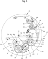
- THE figures 9 And 10 illustrate two intermediate positions of the chronograph mechanism 10 according to the invention between the reset position of the figure 5 and the neutral rest position of the Figure 3 , during the return movement of the hammer 50.
- Figure 9 corresponds to the position of the hammer 50 when it is deflected by the slope of the second inclined surface 147a of the second portion 147 of the guide cam 145.
- the hammer then makes a trajectory in a first direction t1.
- FIG 10 corresponds to the position of the hammer 50 when it is held apart by the second flat 147b of the second portion 147 of the guide cam 145. From this position, when the guide pin 55 is no longer deflected by the cam guide 145, under the effect of the hammer spring (not shown), the hammer 50 returns to abut against the third guide pin 73 by performing a trajectory in a second direction t2 to then return to its initial neutral rest position shown over there Figure 3 .
- the invention has been particularly described with a rectilinear trajectory of the hammer in one direction during the forward movement, and in at least two directions during the return movement.
- the invention is also applicable with a hammer configured to cooperate with the reset control and guide members allowing the hammer to have a circular, curvilinear or complex trajectory during the back and forth movement, with a trajectory according to several directions during the return movement so as to create an offset in the return trajectory of the first arm by the use of a disengageable guide cam.
- the chronograph mechanism 10 comprises a column wheel 63 to control the different movements of various levers which are supported against a column or between two columns.
- the operation of a chronograph mechanism 10 with such a column wheel 63 being widely known, it is not necessary to further explain the operation of such a wheel.
- chronograph mechanism 10 can also be a chronograph mechanism with cam replacing the column wheel 63 without departing from the context of the invention.
- the invention also relates to a timepiece, for example a wristwatch, comprising such a clockwork movement.
Landscapes
- Physics & Mathematics (AREA)
- General Physics & Mathematics (AREA)
- Measurement Of Unknown Time Intervals (AREA)
Priority Applications (4)
| Application Number | Priority Date | Filing Date | Title |
|---|---|---|---|
| EP22215514.5A EP4390574A1 (de) | 2022-12-21 | 2022-12-21 | Chronographenmechanismus für uhrwerk und uhr mit einem solchen mechanismus |
| US18/508,304 US12613497B2 (en) | 2022-12-21 | 2023-11-14 | Chronograph mechanism for a horological movement and timepiece comprising such a mechanism |
| JP2023199038A JP7638356B2 (ja) | 2022-12-21 | 2023-11-24 | 時計ムーブメント用クロノグラフ機構及び当該機構を備えた時計 |
| CN202311710171.9A CN118226733A (zh) | 2022-12-21 | 2023-12-13 | 用于钟表机芯的计时机构和包括这种机构的钟表 |
Applications Claiming Priority (1)
| Application Number | Priority Date | Filing Date | Title |
|---|---|---|---|
| EP22215514.5A EP4390574A1 (de) | 2022-12-21 | 2022-12-21 | Chronographenmechanismus für uhrwerk und uhr mit einem solchen mechanismus |
Publications (1)
| Publication Number | Publication Date |
|---|---|
| EP4390574A1 true EP4390574A1 (de) | 2024-06-26 |
Family
ID=84569426
Family Applications (1)
| Application Number | Title | Priority Date | Filing Date |
|---|---|---|---|
| EP22215514.5A Pending EP4390574A1 (de) | 2022-12-21 | 2022-12-21 | Chronographenmechanismus für uhrwerk und uhr mit einem solchen mechanismus |
Country Status (4)
| Country | Link |
|---|---|
| US (1) | US12613497B2 (de) |
| EP (1) | EP4390574A1 (de) |
| JP (1) | JP7638356B2 (de) |
| CN (1) | CN118226733A (de) |
Citations (3)
| Publication number | Priority date | Publication date | Assignee | Title |
|---|---|---|---|---|
| CH585432B5 (de) * | 1971-08-20 | 1977-02-28 | Smiths Industries Ltd | |
| EP1960848B1 (de) * | 2005-11-24 | 2012-06-13 | Vaucher Manufacture Fleurier S.A. | Hammer einer uhr |
| EP1746471B1 (de) * | 2005-07-20 | 2019-09-18 | Breitling AG | Null-Rückstellungsvorrichtung für zwei Zeitzähler |
Family Cites Families (4)
| Publication number | Priority date | Publication date | Assignee | Title |
|---|---|---|---|---|
| CH500273A4 (de) * | 1973-04-06 | 1975-05-30 | ||
| CH707233A1 (de) | 2012-11-22 | 2014-05-30 | Eterna Ag Uhrenfabrik | Minutzenzähler einer Uhr, insbesondere eines Chronographen. |
| EP3324245A1 (de) | 2016-11-17 | 2018-05-23 | Nogerah SA | System zum sofortantrieb und chronographenmechanismus, der mit einem solchen system ausgestattet ist |
| CH718458A9 (fr) * | 2021-03-18 | 2022-11-30 | Mft Dhorlogerie Audemars Piguet Sa | Mécanisme d'actionnement pour mouvement horloger, en particulier mécanisme de chronographe comportant un tel mécanisme d'actionnement. |
-
2022
- 2022-12-21 EP EP22215514.5A patent/EP4390574A1/de active Pending
-
2023
- 2023-11-14 US US18/508,304 patent/US12613497B2/en active Active
- 2023-11-24 JP JP2023199038A patent/JP7638356B2/ja active Active
- 2023-12-13 CN CN202311710171.9A patent/CN118226733A/zh active Pending
Patent Citations (3)
| Publication number | Priority date | Publication date | Assignee | Title |
|---|---|---|---|---|
| CH585432B5 (de) * | 1971-08-20 | 1977-02-28 | Smiths Industries Ltd | |
| EP1746471B1 (de) * | 2005-07-20 | 2019-09-18 | Breitling AG | Null-Rückstellungsvorrichtung für zwei Zeitzähler |
| EP1960848B1 (de) * | 2005-11-24 | 2012-06-13 | Vaucher Manufacture Fleurier S.A. | Hammer einer uhr |
Non-Patent Citations (1)
| Title |
|---|
| C.-A. REYMONDIN ET AL.: "Théorie d'horlogerie", FÉDÉRATION DES ECOLES TECHNIQUES, 2015, pages 238 |
Also Published As
| Publication number | Publication date |
|---|---|
| US12613497B2 (en) | 2026-04-28 |
| JP7638356B2 (ja) | 2025-03-03 |
| CN118226733A (zh) | 2024-06-21 |
| US20240210893A1 (en) | 2024-06-27 |
| JP2024089632A (ja) | 2024-07-03 |
Similar Documents
| Publication | Publication Date | Title |
|---|---|---|
| EP3545370B1 (de) | Rotierender resonator mit flexiblem führungssystem auf basis einer abgelösten ankerhemmung | |
| CH709328A2 (fr) | Echappement, mouvement de pièce d'horlogerie et pièce d'horlogerie. | |
| EP3059642B1 (de) | Uhrmechanismus | |
| EP3040783A1 (de) | Untereinheit für einen mechanismus zur einstellung der geschwindigkeit in einem uhrwerk, und ein solcher mechanismus | |
| CH710925A2 (fr) | Mécanisme d'échappement. | |
| EP3770696B1 (de) | Anschlagkäfig für uhr mit aufzugstift und anschlagstift | |
| EP3770693B1 (de) | Anschlagmechanismus für uhrenkäfig mit anschlagrad | |
| CH720361A2 (fr) | Mécanisme de chronographe pour mouvement d'horlogerie | |
| EP3770694B1 (de) | Anschlagkäfig für uhr mit zwei elastischen anschlagelementen | |
| CH714361A2 (fr) | Résonateur rotatif à guidage flexible entretenu par un échappement libre à ancre. | |
| EP4047425A1 (de) | Vorrichtung zum vorübergehenden anhalten des betriebs einer mechanischen uhr | |
| WO2025012772A1 (fr) | Mécanisme horloger | |
| EP1960843B1 (de) | Uhrwerk | |
| EP4451066B1 (de) | Uhrwerk, das einen chronographenmechanismus umfasst, insbesondere mit sekundenbruchteilen | |
| CH716423B1 (fr) | Ensemble limiteur d'horlogerie pour une montre comportant au moins un tourbillon ou un carrousel. | |
| EP1960846B1 (de) | Uhrwerk | |
| CH720711A2 (fr) | Mouvement d'horlogerie comportant un mécanisme de chronographe, notamment à seconde foudroyante | |
| EP3770695B1 (de) | Anschlagkäfig für uhr mit käfiganschlagblatt | |
| EP4421567A1 (de) | Auslösemechanismus eines uhrwerksmechanismus und uhr mit solch einem auslösemechanismus | |
| EP4564106A1 (de) | Reguliersystem für eine uhr | |
| WO2025037233A1 (fr) | Mécanisme horloger pour chronographe à rattrapante | |
| EP4390555A1 (de) | Konstantkrafthemmungsmechanismus für uhrwerk | |
| EP4498175A1 (de) | Uhreinstellorgan mit hakenbetätigungssystem | |
| CH716424B1 (fr) | Ensemble limiteur d'horlogerie pour une montre comportant au moins un tourbillon ou un carrousel. | |
| CH718362A2 (fr) | Dispositif pour effectuer un arrêt momentané du fonctionnement d'une montre mécanique. |
Legal Events
| Date | Code | Title | Description |
|---|---|---|---|
| PUAI | Public reference made under article 153(3) epc to a published international application that has entered the european phase |
Free format text: ORIGINAL CODE: 0009012 |
|
| STAA | Information on the status of an ep patent application or granted ep patent |
Free format text: STATUS: THE APPLICATION HAS BEEN PUBLISHED |
|
| AK | Designated contracting states |
Kind code of ref document: A1 Designated state(s): AL AT BE BG CH CY CZ DE DK EE ES FI FR GB GR HR HU IE IS IT LI LT LU LV MC ME MK MT NL NO PL PT RO RS SE SI SK SM TR |
|
| P01 | Opt-out of the competence of the unified patent court (upc) registered |
Free format text: CASE NUMBER: APP_50348/2024 Effective date: 20240905 |
|
| STAA | Information on the status of an ep patent application or granted ep patent |
Free format text: STATUS: REQUEST FOR EXAMINATION WAS MADE |
|
| 17P | Request for examination filed |
Effective date: 20241206 |
|
| GRAP | Despatch of communication of intention to grant a patent |
Free format text: ORIGINAL CODE: EPIDOSNIGR1 |
|
| STAA | Information on the status of an ep patent application or granted ep patent |
Free format text: STATUS: GRANT OF PATENT IS INTENDED |
|
| INTG | Intention to grant announced |
Effective date: 20260306 |