EP4390701A1 - Überwachungsvorrichtung zur kommunikation mit einer edge-computing-vorrichtung an bord eines flugzeugs und elektronisches system zur ausführung von softwareanwendungen dafür - Google Patents
Überwachungsvorrichtung zur kommunikation mit einer edge-computing-vorrichtung an bord eines flugzeugs und elektronisches system zur ausführung von softwareanwendungen dafür Download PDFInfo
- Publication number
- EP4390701A1 EP4390701A1 EP23218560.3A EP23218560A EP4390701A1 EP 4390701 A1 EP4390701 A1 EP 4390701A1 EP 23218560 A EP23218560 A EP 23218560A EP 4390701 A1 EP4390701 A1 EP 4390701A1
- Authority
- EP
- European Patent Office
- Prior art keywords
- board
- execution
- calculation
- computing device
- peripheral
- Prior art date
- Legal status (The legal status is an assumption and is not a legal conclusion. Google has not performed a legal analysis and makes no representation as to the accuracy of the status listed.)
- Pending
Links
Images


Classifications
-
- G—PHYSICS
- G06—COMPUTING OR CALCULATING; COUNTING
- G06F—ELECTRIC DIGITAL DATA PROCESSING
- G06F11/00—Error detection; Error correction; Monitoring
- G06F11/30—Monitoring
- G06F11/32—Monitoring with visual or acoustical indication of the functioning of the machine
- G06F11/323—Visualisation of programs or trace data
-
- G—PHYSICS
- G05—CONTROLLING; REGULATING
- G05B—CONTROL OR REGULATING SYSTEMS IN GENERAL; FUNCTIONAL ELEMENTS OF SUCH SYSTEMS; MONITORING OR TESTING ARRANGEMENTS FOR SUCH SYSTEMS OR ELEMENTS
- G05B19/00—Program-control systems
- G05B19/02—Program-control systems electric
- G05B19/18—Numerical control [NC], i.e. automatically operating machines, in particular machine tools, e.g. in a manufacturing environment, so as to execute positioning, movement or co-ordinated operations by means of program data in numerical form
- G05B19/4155—Numerical control [NC], i.e. automatically operating machines, in particular machine tools, e.g. in a manufacturing environment, so as to execute positioning, movement or co-ordinated operations by means of program data in numerical form characterised by program execution, i.e. part program or machine function execution, e.g. selection of a program
-
- G—PHYSICS
- G06—COMPUTING OR CALCULATING; COUNTING
- G06F—ELECTRIC DIGITAL DATA PROCESSING
- G06F11/00—Error detection; Error correction; Monitoring
- G06F11/30—Monitoring
- G06F11/3003—Monitoring arrangements specially adapted to the computing system or computing system component being monitored
- G06F11/302—Monitoring arrangements specially adapted to the computing system or computing system component being monitored where the computing system component is a software system
-
- G—PHYSICS
- G05—CONTROLLING; REGULATING
- G05B—CONTROL OR REGULATING SYSTEMS IN GENERAL; FUNCTIONAL ELEMENTS OF SUCH SYSTEMS; MONITORING OR TESTING ARRANGEMENTS FOR SUCH SYSTEMS OR ELEMENTS
- G05B2219/00—Program-control systems
- G05B2219/30—Nc systems
- G05B2219/31—From computer integrated manufacturing till monitoring
- G05B2219/31112—Interface, SIOMS standard I-O for mechatronic systems, device drivers
Definitions
- the present invention relates to a supervision device configured to communicate with a peripheral computing device on board an aircraft, as well as an associated electronic software application execution system.
- the invention lies in the field of avionics, and more particularly in the field of executing software applications on board an aircraft.
- the invention applies to any type of aircraft, with or without a pilot on board, both in a civil or military context.
- aircraft include on-board electronic devices (or on-board computers) with certified operation according to an avionics certification standard.
- any software application embedded in this type of device must be compliant and certified.
- on-board software applications which are useful for navigation, for controlling on-board equipment, for example various sensors, e.g. optical or thermal cameras, radars, etc., are limited in number, because they are expensive to develop and maintain. certify.
- the computing resources e.g. CPU, ROM, RAM
- certified on-board computers are generally pre-allocated, to guarantee security and limit any risk of hacking or external intrusion.
- the hardware and software structure of certified operating on-board computers is rigid, any development or modification being slow and costly.
- the supervision device allows an operator to follow, in real time or in offset time, the progress of a mission of execution of a plurality of software applications by an aircraft, for example from a base located on the ground. This makes it possible to detect possible operating problems and to improve or apply predictive maintenance for the on-board peripheral computing device and/or on-board electronic devices with certified operation.
- the supervision device according to the invention may also have one or more of the characteristics below, taken independently or in all technically conceivable combinations.
- the supervision device is configured, for a mission of executing a plurality of software applications on a trajectory of the aircraft, to display on the human machine interface a plurality of trajectory portions, each trajectory portion corresponding to an operating state of the peripheral computing device and/or on-board electronic devices.
- the supervision device is further configured to display information relating to each portion of trajectory, indicating said operating state and a root cause of the operating state.
- the root cause is received from the on-board peripheral device or determined, by calculation, by said supervisory device, based on said observability signals and additional information including environment information and connectivity information.
- the supervision device is configured to perform the calculation a) and the display b) either substantially in real time, upon receipt of said observability signals from the on-board calculation device, or subsequently.
- the supervision device is configured to implement a digital twin of the aircraft.
- the invention relates to an electronic system for executing software applications comprising a calculation system onboard an aircraft, and at least one remote calculation system located on the ground, the onboard calculation system comprising at least one on-board electronic device operating certified according to an avionics certification standard, and a peripheral computing device, the remote computing system comprising a supervision device as briefly described above.
- the electronic system for executing software applications may also have one or more of the characteristics below, taken independently or in any technically conceivable combination.
- the supervision device is configured to display, following the determination of the execution, for a software application, in two parts, respectively a first part executed by the on-board peripheral calculation device and a second part executed by the remote calculation system , to display information relating to said first and second parts.
- the supervisor is further configured to display a root cause of the two-part execution determination.
- the electronic system for executing software applications, on board an aircraft finds applications in all types of aircraft, and more particularly for lightweight aircraft such as drones, carrying equipment such as image sensors, such as optical cameras, thermal cameras, imaging radars, positioning sensors (GNSS, inertial units, anemo-barometric sensors, radio navigation beacons, triangulation), measuring systems such as telemeters, sensors and monitoring systems weather, traffic or terrain, radio or digital communications systems, radio frequency (RF) antennas, etc.
- image sensors such as optical cameras, thermal cameras, imaging radars, positioning sensors (GNSS, inertial units, anemo-barometric sensors, radio navigation beacons, triangulation
- GNSS positioning sensors
- inertial units inertial units
- anemo-barometric sensors anemo-barometric sensors
- radio navigation beacons triangulation
- measuring systems such as telemeters, sensors and monitoring systems weather, traffic or terrain, radio or digital communications systems, radio frequency (RF) antennas, etc.
- RF radio frequency
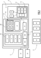
- FIG. 1 schematically illustrates a system 2 which is an electronic system for executing embedded software.
- System 2 is a system allowing on-board-ground cooperation.
- the system 2 comprises on the one hand an on-board calculation system 4, comprising devices on board an aircraft 6, and on the other hand, one or more ground calculation systems 8.
- the on-board calculation system 4 comprises a set 10 of on-board electronic devices operating certified according to an avionics certification standard, comprising at least one on-board computer 12, and on-board equipment 14, e.g. sensors, for example cameras, radars, actuator, navigation system, autopilot system, flight controls, geolocation system, certified monitoring systems (terrain traffic, weather), certified communication systems (e.g. Radios).
- sensors for example cameras, radars, actuator, navigation system, autopilot system, flight controls, geolocation system, certified monitoring systems (terrain traffic, weather), certified communication systems (e.g. Radios).
- certified operating on-board devices comply with one or more of the following standards: RTCA DO178B for the software certification level and RTCA DO160 for the hardware certification part, AEEC Arinc 702A for the flight management system (Flight Management System) , etc.
- the on-board computer 12 is configured to implement certified software applications, for example applications for aiding navigation, controlling the operation of the sensors 14 and receiving and processing data from sensors 14.
- the on-board computer 12 comprises hardware resources, in particular a central processing unit comprising in particular one or more processors 15, adapted to execute computer program instructions when the processing unit is powered on.
- the on-board computer 12 also includes information storage units 16, including in particular random access memory units (RAM memory), ROM type memory units, adapted to store data and executable code instructions, a communication interface 18 and a man-machine interface 17.
- RAM memory random access memory units
- ROM type memory units adapted to store data and executable code instructions
- communication interface 18 adapted to store data and executable code instructions
- man-machine interface 17 man-machine interface
- the on-board computing system 4 advantageously comprises an on-board peripheral computing device 20.
- This peripheral computing device 20 advantageously makes it possible to increase the on-board computing capacity, in a more flexible manner, allowing easier and less costly software and hardware updates than for the on-board computer 12.
- the peripheral computing device 20 comprises a first communication interface 22 configured to communicate, according to a first communication protocol, with the on-board electronic device(s) with certified operation, and in particular with the on-board computer 12.
- the first communication interface 22 is configured to communicate, using bidirectional communication, with the communication interface 18 of the on-board computer 12.
- the communication between the peripheral computing device 20 and the on-board computer 12 is a wired communication.
- the communication between the peripheral computing device 20 and the on-board computer 12 is a wireless communication, for example of the Wifi or Bluetooth type.
- the peripheral calculation device 20 comprises a second radio communication interface 24, configured to communicate, according to a second radio communication protocol, with the remote calculation system(s) 8 located on the ground.
- the second communication protocol is a radio communication protocol, for example a standard 4G or 5G mobile telephone protocol, the SATCOM satellite communication protocol, the Datalink AOC/ATC protocol (for “Aeronautical Operation Control” / “Air Traffic Control”). ").
- the peripheral calculation device 20 comprises several second radio communication interfaces 24, according to several radio communication protocols, making it possible to communicate with external devices, via a second radio communication interface 24A making it possible to communicate with the calculation system 8 and a second radio communication interface 24B making it possible to communicate according to another radio communication protocol, for example with one or more external control devices 25, configured to send commands for implementing software applications by the peripheral computing device 20 and to receive data, in particular data from on-board sensors, in return.
- An external control device 25 is for example a tablet, a laptop, a smartphone (or smartphone).
- Such an external control device 25 is for example also on board the aircraft.
- such an external control device 25 is operated by an operator on board the aircraft, for example a pilot of the aircraft, via a man-machine interface, eg a touch screen or any other suitable type of man-machine interface (not shown here).
- a man-machine interface eg a touch screen or any other suitable type of man-machine interface (not shown here).
- the peripheral computing device 20 is configured to communicate, bidirectionally, with the remote computing system 8 and with at least one external control device 25.
- the peripheral computing device 20 further comprises a processing unit 26, comprising one or more processors (CPU or GPU), and at least one electronic memory unit 28, these elements being adapted to communicate via a communication bus (not shown ).
- a processing unit 26 comprising one or more processors (CPU or GPU), and at least one electronic memory unit 28, these elements being adapted to communicate via a communication bus (not shown ).
- the electronic memory unit 28 notably comprises RAM, ROM type memories, any type of non-volatile memory (for example EPROM, EEPROM, FLASH, NVRAM).
- RAM random access memory
- ROM type memories any type of non-volatile memory (for example EPROM, EEPROM, FLASH, NVRAM).
- All the processing unit(s) 26 and electronic memory unit(s) 28 form the local computing resources of the peripheral computing device 20.
- the peripheral computing device 20 is modular, several processing and memory units can be added, which allows a dynamic increase in the available resources, depending on needs.
- the dynamic increase in available resources is limited, in practice, in certain embodiments, by the consumption of electrical energy and/or the total weight of such a peripheral computing device 20. Indeed, the total weight can be limited for certain types of aircraft, for example for drones, depending on the aerodynamic lift of the drone, and/or its maneuverability. Likewise, the consumption of electrical energy when the peripheral computing device executes software applications with maximum occupation of computing and storage resources 26, 28, must be taken into account, in order to ensure the achievement of a planned mission. , over a planned mission duration.
- mission means a set of tasks to be carried out, for example by on-board sensors, linked to associated flight indications (trajectories, durations, waypoints, etc.).
- the electronic memory unit 28 is configured in particular to store a library of software applications 35, comprising a variable number of software applications APP 1 , APP 2 ... APP i .
- Each software application is stored as executable program code.
- executable application is also used to refer to such a software application.
- software applications are obtained by downloading (in English “Dataloading”), from an external control device 25 or from a ground calculation system 8.
- an APP i software application can be obtained from a computer-readable medium, for example a medium capable of memorizing electronic instructions and being coupled to a bus of a computer system (eg USB key , non-volatile memory (e.g. EPROM, EEPROM, FLASH, NVRAM), a magnetic card or an optical card).
- a computer-readable medium for example a medium capable of memorizing electronic instructions and being coupled to a bus of a computer system (eg USB key , non-volatile memory (e.g. EPROM, EEPROM, FLASH, NVRAM), a magnetic card or an optical card).
- the electronic memory unit 28 is also configured to store data and results 37, in particular data obtained from on-board electronic devices with certified operation (for example, images obtained by on-board sensors, operating data, data relating to the trajectory or performance of the aircraft), and the results obtained by executing the APP i software applications.
- data and results 37 can be transmitted to the ground as “observability signals”, allowing a human operator or a system to monitor the proper functioning of the overall system, ensure debugging, and perform simulations or replay ( in English “replay”) of mission.
- the electronic memory unit 28 is configured to store parameters useful for the implementation of a method of executing software applications as described below, in particular parameters relating to the allocation of resources calculations per software application, where applicable, a table of execution priorities or a set of static rules defining execution priorities of software applications.
- the modules 30, 32, 34, 36 are adapted to cooperate, as described in more detail below, to implement a method of executing software applications as described in more detail below.
- the modules 30, 32, 34, 36 are produced in the form of software instructions forming a computer program, which, when executed by a computer, implements a method of executing software applications according to the invention.
- the computer program comprising software instructions is further capable of being recorded on a non-transitory computer-readable medium.
- the computer-readable medium is, for example, a medium capable of storing electronic instructions and of being coupled to a bus of a computer system.
- the readable medium is an optical disk, a magneto-optical disk, a ROM memory, a RAM memory, any type of non-volatile memory (for example EPROM, EEPROM, FLASH, NVRAM), a magnetic card or an optical card.
- the modules 30, 32, 34, 36 are each produced in the form of programmable logic components, such as FPGAs (from the English Field Programmable Gate Array ), microprocessors, GPGPU components (from the English General-purpose processing on graphics processing ), or even dedicated integrated circuits, such as ASICs ( Application Specifies Integrated Circuit ).
- programmable logic components such as FPGAs (from the English Field Programmable Gate Array ), microprocessors, GPGPU components (from the English General-purpose processing on graphics processing ), or even dedicated integrated circuits, such as ASICs ( Application Specifies Integrated Circuit ).
- the peripheral computing device 20 is thus configured to locally execute a first part of the applications to be executed, and to delegate, where appropriate, a second execution part to the remote computing system 8. Indeed, in certain cases, the first part is equal to 100% of the software application to be executed, in which case there is no need to delegate a second execution part to the remote calculation system.
- the remote computing system 8 comprises one or more interconnected electronic computing devices.
- the remote computing system 8 comprises or is connected to a cloud of computers or “cloud” in English.
- the remote calculation system 8 comprises a processing unit 40, comprising one or more calculation processors, an electronic memory unit 42, a ground communication interface 44, adapted to communicate with the second communication interface 24 of the on-board peripheral computing device 20, and a man-machine interface 46.
- the processing unit 40 is configured to execute parts of the APPi software applications, by executing a corresponding part of the executable code, stored in the electronic memory unit 42, upon request from the peripheral computing device 20, at memorize data and calculation results and transmit these calculation results, via the communication interface 44, to the peripheral calculation device 20 and/or to an external control device 25.
- the remote calculation system 8 located on the ground is also configured to transmit data and calculation results to another aircraft 6, for example as part of a mission involving a plurality of aircraft.
- execution stack management is dynamic and flexible, and makes it possible to take into account one or more criteria among: a criterion of availability of computational resources, a criterion of connectivity, a criterion of criticality of the data, a criterion of priority, as explained in more detail below.
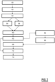
- FIG. 2 is a block diagram of the main stages of a method for executing software applications, implemented in the electronic system 2 for executing software applications, in a first embodiment.
- the method comprises a set of steps implemented by a processing unit, comprising at least one processor, of an on-board peripheral computing device 20. These steps are executed after power on the peripheral computing device.
- the method includes an initialization step 50, which is a preliminary step, executed in a delayed time compared to the other steps of the method.
- the first and second communication interfaces are initialized, in particular configured with respective communication addresses, so as to allow communications, on the one hand with the on-board electronic devices 10 with certified operation, on the other hand with external devices 25, and with the ground calculation system 8.
- the peripheral computing device executes the initialization of the communication interfaces following a request, for example transmitted by an operator or by an external application via an external control device 25.
- first configuration structures e.g. first configuration tables are received from at least one computer. edge 12, and stored in a local electronic memory unit of the peripheral computing device.
- second configuration structures e.g. second configuration tables are received from at least one remote calculation system 8, and stored in a local electronic memory unit of the peripheral computing device.
- the first and second configuration structures notably contain connectivity information (e.g. identifiers and communication addresses).
- the APP i software application library is re-initialized.
- the data and results 37 stored in the memory unit of the peripheral computing device are erased during initialization 50.
- the APP i applications and/or the data and results stored during prior use of the peripheral computing device are retained.
- parameters useful for implementing the method of executing software applications are obtained and stored. These parameters include in particular parameters relating to the allocation of resources per software application, for example for a minimum allocation per software application, a maximum allocation or an average allocation, and/or a table of execution priorities or a set of rules statics defining execution priorities of software applications.
- the resource allocation parameters contain for example: computing power, for example expressed in processor clock frequency (e.g. in GHz), and/or an associated storage capacity, expressed for example in kilobytes, and/or a percentage of first communication bandwidth with the certified operating on-board electronic devices, and/or a percentage of second communication bandwidth with the remote computing system.
- computing power for example expressed in processor clock frequency (e.g. in GHz)
- an associated storage capacity expressed for example in kilobytes, and/or a percentage of first communication bandwidth with the certified operating on-board electronic devices, and/or a percentage of second communication bandwidth with the remote computing system.
- a vector comprising only a subpart of the allocation parameters is defined.
- the method comprises a step 52 of receiving a software application addition/deletion command, coming from an external control device, or from the ground calculation system or from one of the on-board devices.
- a deletion command is received from an external control device or an authorized operator, for example owner of the software application to be deleted.
- authorized operator authentication is implemented, by an authentication method, numerous variants of such authentication methods being known.
- the addition/update of an application is carried out by an operator, preferably an authorized operator, by means of a data storage medium (e.g. USB key).
- a data storage medium e.g. USB key
- the method includes an application management step 54, which updates the library of software applications according to the commands received.
- Step 54 includes receiving a new software application or an update of a previously stored software application, by means of a wired connection or to be downloaded by means of a radio communication link, then storing new APP j applications, and/or the deletion of APP i applications from the application library.
- the software applications stored in the application library 35 are adapted to provide at least one control parameter and/or receive at least one piece of data from at least one on-board electronic device.
- the method implements validations of integrity and validity of downloaded applications, by usual methods (authentication, cyclic redundancy check (CRC) validation, etc.).
- the method includes enabling execution 56 of one or more of the stored software applications, which then become software applications to be executed.
- Execution activation is based on either receiving an execution request from at least one software application from an external device or on validating an execution activation condition.
- condition for activating the execution of a software application APP i is the end of execution of a software application APP j or corresponds to a reduction in the resource requirement of the software application Appj compatible with its functioning.
- commands to pause or stop execution of one or more software applications can also be received (step 58), their management being carried out directly.
- Stopping execution frees up resources and therefore redistributes available resources. As with execution, automatic validation of the stopping condition also makes it possible to trigger the stopping or pausing of the execution of an application.
- Steps 54, 56, 58 are preferably executed in the background, substantially in parallel, so as to constantly take into account the reception of new software applications or the updating of existing software applications, as well as the activations of execution and commands to stop or pause execution.
- the method further comprises a step 60 of managing an execution stack of the software applications to be executed. This step is repeated regularly, at predetermined time intervals or upon event (for example request to start a new application, event which terminates or significantly modifies the computational resource requirements of an application).
- the management step 60 implements, for each application to be executed APP k , an allocation of resources, in particular of computational resources (processor and memory) of the peripheral computing device, called local resources, to execute all or part of the application to run APP k .
- the same quantity of local resources is allocated to each APP k , the quantity being predetermined in initialization step 50.
- the resources are allocated dynamically, for example according to an expected response time per application, which makes it possible to dynamically define execution priorities.
- the allocation of resources is carried out according to priorities, defined in a previously recorded execution priority table or according to a previously programmed set of static rules.
- the priorities are dynamically updated by means of an external control device.
- the management module also implements a priority criterion.
- a criterion of availability of computational resources is implemented to determine the local or remote execution of each software application.
- the communication conditions according to the second radio communication protocol may vary depending on the movement, weather conditions, etc.
- Detection can be done using cameras embedded in the drone, whose resolution, width of field and frame rate will have a direct impact on the need for resources:
- a video sequence in 4K definition/resolution, wide field, at 50 images/sec will, for example, require much more storage resources (RAM/ROM) and CPU (or GPU) resources for its processing, than a low resolution video sequence (480p for example), or with a narrower field width or at 25 frames/sec.
- the electricity consumption of the drone will also be a function of the bandwidth communication between the board and the ground, and the quality of the network, which determines the means of communication used and the power necessary to power the transmitting and receiving antennas.
- the system may choose to have all of the mapping and detection and geo-referencing calculations carried out locally by the APP k,1 application.
- the system may choose to have the mapping and detection and geo-referencing calculations carried out locally by the APP k,21 application by sending images taken locally by the camera to the ground device.
- the first and second parts to be executed locally/remotely respectively are for example defined in terms of percentage of code to be executed.
- the first part is equal to 100% of the application to be executed, in which case there is no need to transfer part of the execution to the ground calculation system.
- software applications are coded to be executed in parts.
- all or part of each software application is also previously stored in the electronic memory 42 of the remote calculation system 8, which facilitates the delegation of calculations.
- a data criticality criterion is implemented to determine the second APP part k,2 , to be executed on the ground, thus making it possible to avoid transmitting data or results considered sensitive or confidential to the calculation system on the ground, via the second transmission interface.
- Such data considered confidential, and therefore to be protected are for example data relating to the performance of the aircraft, or even confidential data of the client who owns the application to be executed (e.g. airline, institution, company).
- the method includes a remote execution request 62, comprising the transmission of associated information (e.g. execution point, data to be used, intermediate results).
- associated information e.g. execution point, data to be used, intermediate results.
- the executable code forming the second part APP k,2 is transmitted to the remote calculation system during step 62.
- the remote calculation system executes the second part APP k,2 of software application (step 64), and transmits the results of the calculations to the on-board peripheral calculation device (step 66).
- the peripheral computing device receives the results in step 68.
- the results are consolidated in consolidation step 70.
- the consolidation involves the temporal and/or spatial synchronization of the results, and/or a fusion of data, for example a fusion of inertial sensor data with positions calculated by software processing from camera data. view.
- the consolidated results are stored and/or transmitted (step 72) to the external control device, initiator of the execution of the software application.
- FIG. 3 illustrates a second embodiment of the application execution method implemented in the application execution system 2.
- a supervision device which is either one of the external control devices, or a device of the calculation system remote on the ground, implements real-time supervision of the operation of the on-board peripheral computing device.
- the supervision device is part of the remote ground computing system and includes a man-machine interface, allowing the display of information to an operator and the reception of commands from the operator.
- the method includes supervision 80 implemented by the supervision device.
- a schematic representation of a supervision device 82 is provided in the Figure 4 .
- the supervision device 82 is a programmable electronic device, comprising a communication interface 84 adapted to communicate with the second communication interface 24 of the on-board peripheral computing device 20.
- Man-machine interface 85 comprising in particular one or more display screens, touchscreen(s) or not, and means (keyboard, mouse, etc.), allowing interaction with an operator.
- the supervision device 82 also includes a processing unit (e.g. one or more processors) 86 and an electronic memory unit 88.
- the units 84, 85, 86, 88 are adapted to communicate via an internal communication bus.
- the processor 86 is configured to implement a calculation module 90, configured to calculate an operating state of said peripheral computing device and an execution state of said at least one software application from observability signals received from the device peripheral calculation 6, and a module 92 for displaying, in graphic form, on the man-machine interface 85, the operating/execution states, in particular during a mission requiring the execution of software applications along 'a trajectory, or after the execution of the mission.
- a calculation module 90 configured to calculate an operating state of said peripheral computing device and an execution state of said at least one software application from observability signals received from the device peripheral calculation 6, and a module 92 for displaying, in graphic form, on the man-machine interface 85, the operating/execution states, in particular during a mission requiring the execution of software applications along 'a trajectory, or after the execution of the mission.
- the modules 90, 92 are adapted to cooperate, as described in more detail below, to implement the supervision step 80 described in detail below.
- the modules 90, 92 are produced in the form of software instructions forming a computer program, which, when executed by a computer, implements the supervision method described.
- the computer program comprising software instructions is further capable of being recorded on a non-transitory computer-readable medium.
- the media readable by computer is for example, a medium capable of memorizing electronic instructions and of being coupled to a bus of a computer system.
- the readable medium is an optical disk, a magneto-optical disk, a ROM memory, a RAM memory, any type of non-volatile memory (for example EPROM, EEPROM, FLASH, NVRAM), a magnetic card or an optical card.
- the modules 90, 92 are each produced in the form of programmable logic components, such as FPGAs (from the English Field Programmable Gate Array ), microprocessors, GPGPU components (from the English General-purposeprocessing on graphics processing ), or even dedicated integrated circuits, such as ASICs (from the English Application Specifies Integrated Circuit ).
- programmable logic components such as FPGAs (from the English Field Programmable Gate Array ), microprocessors, GPGPU components (from the English General-purposeprocessing on graphics processing ), or even dedicated integrated circuits, such as ASICs (from the English Application Specifies Integrated Circuit ).
- Supervision 80 is carried out continuously, the supervision device comprising a man-machine interface and being configured to receive observability signals from the peripheral calculation device 20.
- observability signals from the peripheral computing device include data relating to local computing resources and information relating to the execution of at least one of the software applications.
- the observability signals include in particular information relating to the use of local resources of the peripheral computing device and the stack of applications to be executed/being executed.
- the supervision device 82 is configured to calculate an operating state of the peripheral computing device and an execution state of the or each software application from the observability signals received.
- the supervision device 82 then implements, for example, displays on the man-machine interface 85, representative of the operating state of the peripheral computing device (state of local resources, connectivity) and the execution state of the applications , optionally with additional data and results from these applications. These displays follow, in one embodiment, substantially in real time, the operation of the peripheral computing device. This allows an operator to set execution priorities in real time, allowing execution of certain software applications to be prioritized and other software applications to be low priority or paused, and/or resource allocations to be changed. in real time.
- Commands relating to the execution priorities of the software applications and/or modifications to the allocation of resources are then transmitted via the supervision device to the on-board peripheral computing device.
- the supervision extends to all on-board devices, including devices with certified operation, then allowing supervision overall use of on-board resources. Indeed, via the on-board peripheral computing device, data provided by sensors or on-board devices are also transmitted to the supervision device for display.
- execution reports e.g. files, tables
- additional information including environmental information and connectivity information
- the set of information recorded in the report(s) includes the observability signals, also transmitted to the supervision device progressively.
- the set of information includes all the states of the execution stack, and the computational/hardware resources of the peripheral computing device, for example the software applications executed, the description of the computational resources allocated, the data and results, as well as additional information such as: the meteorological situation, the availability of communication interfaces, the bandwidth available for communications with the ground computing system, internal operating data of the systems, the energy consumption taken by each application, and by the other systems of the aircraft, the flight profile.
- the execution report(s) containing this set of information are transmitted to the ground supervision device.
- the supervision device is configured to display, in cooperation with graphic representation mechanisms on the man-machine interface 85, a complete progress of the mission (replay), in particular successive states of the peripheral computing device and, optionally, on-board electronic devices, which allows maintenance and debugging operations.
- a replay phase also makes it possible to recalculate the parameters provided in the initialization step 50 such as the minimum, maximum or average allocation of the resources of the peripheral computing device.
- FIG. 5 illustrates an example of display 85 on a human machine interface of a supervision device, hereinafter called supervision HMI, in the context of a mission carried out by a drone equipped with a peripheral computing device 20 as described above.
- supervision HMI a supervision device
- the illustrated example is based on the example of the mission of capturing images by the onboard sensors of a drone, detecting and mapping obstacles such as electricity pylons.
- the trajectory carried out by the drone is illustrated, and divided into several portions of different operating trajectory, as well as information Info1, ..., Info5 relating to the operating states of the peripheral computing device, to the operating states. execution of software applications, and optionally additional connectivity and/or context information (e.g. meteorological) for each portion of trajectory.
- the mission takes place between a starting point D and an ending point A, which can be confused.
- the scales are for example latitude (ordinate) and longitude (abscissa).
- the supervision HMI thus makes it possible to follow the evolution of the drone's trajectory, on which information obtained from other observability signals is superimposed.
- the graphic aspect of the trajectory is a means of illustrating the events linked to the mission.
- the trajectory referenced T D,1 in solid lines, starting from the starting point D and up to the point P1, corresponds to nominal operation in which the image capture is carried out entirely on board by the APP application k,1 .
- the drone has just started its mission, its batteries are full, connectivity is good, the CPU and storage memory capacity (local resources of the onboard peripheral device) are correct and therefore allow high resolution images to be taken and processed on board .
- a trajectory “hole” indicates that the information relating to this part of the trajectory could not be transmitted, in the absence of means of communication, for example in the event of loss of the signal.
- GNSS satellite positioning For example, a peripheral computing device has received and recorded information about loss of the GNSS satellite positioning signal from one or more on-board electronic devices with certified operation.
- Info1 information is displayed, indicating the reason for the anomaly observed, for example in the form of a framed message, indicating "satellite location lost", and as an optional complement, a root cause, for example "GNSS Masked ”, when the root cause has been determined.
- the GNSS satellite positioning signal is restored, for example the peripheral computing device has received and recorded information on correct reception of the GNSS satellite positioning signal from one or more on-board electronic devices with certified operation , and can therefore retransmit its position.
- trajectory referenced T 2.3 is illustrated in thin lines, indicating an operating mode for sharing calculations between the on-board peripheral calculation device and the remote calculation system, ie the execution of software applications, for example digital image processing, divided into two parts APP k,1 . and APP k,2 ,, one carried out on board, the other on the ground.
- software applications for example digital image processing
- the allocation of the execution of a part on the ground is due to reaching a threshold of use of the random access memory (RAM) of the peripheral computing device.
- RAM random access memory
- Info2 information relating to the state of the peripheral computing device eg “RAM saturation”
- the sharing of execution between onboard and ground is displayed in connection with the trajectory portion T 2,3 .
- trajectory referenced T 3.4 is represented in the form of thick dotted lines, which indicates that the peripheral calculation device has entered a degraded calculation mode of the video sequences, and has for example chosen to store the sequences on board rather than sending them to the ground.
- the reason for the anomaly can be explained on the supervision HMI in the form of Info3 information, for example in textual form to indicate that the calculation is suspended, and also indicate the root cause of this degraded mode, for example a loss connection between the communication interface of the on-board peripheral computing device and the communication interface of the remote computing device (eg “LTE Lost”).
- This mode corresponds to the case where the Drone cannot carry out the calculations alone and must delegate a part externally (from point P2), but cannot communicate correctly with the remote computing device.
- trajectory referenced T 4.5 is represented in thick solid lines, to indicate a return to nominal mode (identical to the mode between starting point D and point P1).
- a thin dotted line indicates that the drone's mission (here obstacle detection and mapping) has been interrupted.
- associated information Info5 is displayed, for example textually indicating the termination of the mission, as well as the root cause "user command" which indicates that a human operator has manually terminated the shooting application/ obstacle detection and APP k mapping.
- the on-board hardware resources of an aircraft are increased dynamically and flexibly, and the implementation of client software applications is then possible, while ensuring execution security.
- an aircraft carrying a peripheral computing device as described can be used as a mobile data capture means, like satellites.
- an on-board peripheral device makes it possible to carry out calculations with complex algorithms, which would not be achievable by certified on-board devices due to the limitations imposed by the certifications.
- the flexibility introduced by the possibility of deporting parts of the execution of applications to the ground makes it possible to adapt to the constraints of the aircraft, in particular the constraints of on-board weight and electrical energy consumption.
- the supervision device allows monitoring and supervision, in real time or in shifted time, which allows improvement of the implementation of the on-board calculation device by feedback from the operator, for example debugging as well as judicious management of onboard resources by intervention of an operator.
- commands relating to the implementation of on-board software applications, judiciously chosen are then sent by the supervision device to the on-board peripheral computing device.
Landscapes
- Engineering & Computer Science (AREA)
- Physics & Mathematics (AREA)
- Theoretical Computer Science (AREA)
- General Physics & Mathematics (AREA)
- Computing Systems (AREA)
- Quality & Reliability (AREA)
- General Engineering & Computer Science (AREA)
- Manufacturing & Machinery (AREA)
- Human Computer Interaction (AREA)
- Automation & Control Theory (AREA)
- Mathematical Physics (AREA)
- Data Mining & Analysis (AREA)
- Debugging And Monitoring (AREA)
- Selective Calling Equipment (AREA)
- Stored Programmes (AREA)
Applications Claiming Priority (1)
| Application Number | Priority Date | Filing Date | Title |
|---|---|---|---|
| FR2214318A FR3144330B1 (fr) | 2022-12-22 | 2022-12-22 | Dispositif de supervision configuré pour communiquer avec un dispositif de calcul périphérique embarqué à bord d’un aéronef et système électronique d’exécution d’applications logicielles associé |
Publications (1)
| Publication Number | Publication Date |
|---|---|
| EP4390701A1 true EP4390701A1 (de) | 2024-06-26 |
Family
ID=86007038
Family Applications (1)
| Application Number | Title | Priority Date | Filing Date |
|---|---|---|---|
| EP23218560.3A Pending EP4390701A1 (de) | 2022-12-22 | 2023-12-20 | Überwachungsvorrichtung zur kommunikation mit einer edge-computing-vorrichtung an bord eines flugzeugs und elektronisches system zur ausführung von softwareanwendungen dafür |
Country Status (3)
| Country | Link |
|---|---|
| US (1) | US20240210918A1 (de) |
| EP (1) | EP4390701A1 (de) |
| FR (1) | FR3144330B1 (de) |
Families Citing this family (1)
| Publication number | Priority date | Publication date | Assignee | Title |
|---|---|---|---|---|
| US20250046197A1 (en) * | 2023-08-04 | 2025-02-06 | Microavia International Limited | Generating a flight path when the uav is offline based on terrain data |
Citations (2)
| Publication number | Priority date | Publication date | Assignee | Title |
|---|---|---|---|---|
| US20160117853A1 (en) * | 2014-10-27 | 2016-04-28 | SZ DJI Technology Co., Ltd | Uav flight display |
| CN110868455A (zh) * | 2019-10-29 | 2020-03-06 | 北京邮电大学 | 一种基于空天地远程物联网的计算卸载方法及系统 |
Family Cites Families (2)
| Publication number | Priority date | Publication date | Assignee | Title |
|---|---|---|---|---|
| US11775633B2 (en) * | 2018-12-04 | 2023-10-03 | The Boeing Company | Computer system integrity through a combination of certifiable and qualifiable software |
| US20230333552A1 (en) * | 2022-04-13 | 2023-10-19 | Rotor Technologies, Inc. | Methods and systems for human-in-the-loop vehicular command and control using immersive synthetic vision |
-
2022
- 2022-12-22 FR FR2214318A patent/FR3144330B1/fr active Active
-
2023
- 2023-12-17 US US18/542,743 patent/US20240210918A1/en active Pending
- 2023-12-20 EP EP23218560.3A patent/EP4390701A1/de active Pending
Patent Citations (2)
| Publication number | Priority date | Publication date | Assignee | Title |
|---|---|---|---|---|
| US20160117853A1 (en) * | 2014-10-27 | 2016-04-28 | SZ DJI Technology Co., Ltd | Uav flight display |
| CN110868455A (zh) * | 2019-10-29 | 2020-03-06 | 北京邮电大学 | 一种基于空天地远程物联网的计算卸载方法及系统 |
Also Published As
| Publication number | Publication date |
|---|---|
| FR3144330A1 (fr) | 2024-06-28 |
| FR3144330B1 (fr) | 2025-04-11 |
| US20240210918A1 (en) | 2024-06-27 |
Similar Documents
| Publication | Publication Date | Title |
|---|---|---|
| US9202318B2 (en) | Ground fleet operations quality management system | |
| US11689623B2 (en) | Adaptive real-time streaming for autonomous vehicles | |
| US20220018971A1 (en) | Accuracy of a gnss receiver that has a non-directional antenna | |
| KR101280066B1 (ko) | 선박 운항 시스템, 선박 운항정보 표시방법, 및 그 기록매체 | |
| US20190196061A1 (en) | Weather forecasting system and methods | |
| US8565943B2 (en) | Fleet operations quality management system | |
| GB2601584A (en) | Path planning using forecasts of obscuration and multipath | |
| US20220380048A1 (en) | Recording data associated with an unmanned aerial vehicle | |
| US20180046172A1 (en) | Method, device and system for presenting operation information of a mobile platform | |
| US12517264B2 (en) | Architecture for providing forecasts of low earth orbit (LEO) satellite obscuration and multipath | |
| US20210304621A1 (en) | Utilizing unmanned aerial vehicles for emergency response | |
| US12298409B2 (en) | GNSS forecast and background obscuration prediction | |
| US12425815B2 (en) | System for selectively managing and sharing information based upon telematic information related to mobile devices | |
| US12429599B2 (en) | GNSS forecast and spoofing/jamming detection | |
| US20230128817A1 (en) | Gnss forecast impacting receiver startup | |
| US11945582B2 (en) | Coordinating an aerial search among unmanned aerial vehicles | |
| WO2021046021A1 (en) | Determining whether to service an unmanned aerial vehicle | |
| US20230118232A1 (en) | Gnss forecast and line of sight detection | |
| EP4390701A1 (de) | Überwachungsvorrichtung zur kommunikation mit einer edge-computing-vorrichtung an bord eines flugzeugs und elektronisches system zur ausführung von softwareanwendungen dafür | |
| CN115083037A (zh) | 用于更新地图路网数据的方法、装置、电子设备和车辆 | |
| WO2022250858A1 (en) | Unmanned aerial vehicle module management | |
| FR3072816A1 (fr) | Procede de determination de point(s) limite (s) de decision relative au declenchement d'une manoeuvre d'evitement par un aeronef, dispositif et programme d'ordinateur associes | |
| WO2023168186A1 (en) | Geofence management with an unmanned aerial vehicle | |
| FR3070773A1 (fr) | Systeme de suivi d'un drone, procede et programme d'ordinateur associes | |
| EP4390692A1 (de) | Fahrzeuginterne peripherieberechnungsvorrichtung, elektronisches system zur ausführung von softwareanwendungen und verfahren zur ausführung von softwareanwendungen dafür |
Legal Events
| Date | Code | Title | Description |
|---|---|---|---|
| PUAI | Public reference made under article 153(3) epc to a published international application that has entered the european phase |
Free format text: ORIGINAL CODE: 0009012 |
|
| STAA | Information on the status of an ep patent application or granted ep patent |
Free format text: STATUS: THE APPLICATION HAS BEEN PUBLISHED |
|
| AK | Designated contracting states |
Kind code of ref document: A1 Designated state(s): AL AT BE BG CH CY CZ DE DK EE ES FI FR GB GR HR HU IE IS IT LI LT LU LV MC ME MK MT NL NO PL PT RO RS SE SI SK SM TR |
|
| STAA | Information on the status of an ep patent application or granted ep patent |
Free format text: STATUS: REQUEST FOR EXAMINATION WAS MADE |
|
| 17P | Request for examination filed |
Effective date: 20241128 |
|
| RBV | Designated contracting states (corrected) |
Designated state(s): AL AT BE BG CH CY CZ DE DK EE ES FI FR GB GR HR HU IE IS IT LI LT LU LV MC ME MK MT NL NO PL PT RO RS SE SI SK SM TR |