EP4390761A1 - Etikettenlokalisierungssystem - Google Patents
Etikettenlokalisierungssystem Download PDFInfo
- Publication number
- EP4390761A1 EP4390761A1 EP23218766.6A EP23218766A EP4390761A1 EP 4390761 A1 EP4390761 A1 EP 4390761A1 EP 23218766 A EP23218766 A EP 23218766A EP 4390761 A1 EP4390761 A1 EP 4390761A1
- Authority
- EP
- European Patent Office
- Prior art keywords
- printed circuit
- label
- flexible
- communication module
- module
- Prior art date
- Legal status (The legal status is an assumption and is not a legal conclusion. Google has not performed a legal analysis and makes no representation as to the accuracy of the status listed.)
- Granted
Links
Images

Classifications
-
- G—PHYSICS
- G06—COMPUTING OR CALCULATING; COUNTING
- G06K—GRAPHICAL DATA READING; PRESENTATION OF DATA; RECORD CARRIERS; HANDLING RECORD CARRIERS
- G06K19/00—Record carriers for use with machines and with at least a part designed to carry digital markings
- G06K19/06—Record carriers for use with machines and with at least a part designed to carry digital markings characterised by the kind of the digital marking, e.g. shape, nature, code
- G06K19/067—Record carriers with conductive marks, printed circuits or semiconductor circuit elements, e.g. credit or identity cards also with resonating or responding marks without active components
- G06K19/07—Record carriers with conductive marks, printed circuits or semiconductor circuit elements, e.g. credit or identity cards also with resonating or responding marks without active components with integrated circuit chips
- G06K19/0701—Record carriers with conductive marks, printed circuits or semiconductor circuit elements, e.g. credit or identity cards also with resonating or responding marks without active components with integrated circuit chips at least one of the integrated circuit chips comprising an arrangement for power management
- G06K19/0702—Record carriers with conductive marks, printed circuits or semiconductor circuit elements, e.g. credit or identity cards also with resonating or responding marks without active components with integrated circuit chips at least one of the integrated circuit chips comprising an arrangement for power management the arrangement including a battery
- G06K19/0704—Record carriers with conductive marks, printed circuits or semiconductor circuit elements, e.g. credit or identity cards also with resonating or responding marks without active components with integrated circuit chips at least one of the integrated circuit chips comprising an arrangement for power management the arrangement including a battery the battery being rechargeable, e.g. solar batteries
-
- G—PHYSICS
- G06—COMPUTING OR CALCULATING; COUNTING
- G06K—GRAPHICAL DATA READING; PRESENTATION OF DATA; RECORD CARRIERS; HANDLING RECORD CARRIERS
- G06K19/00—Record carriers for use with machines and with at least a part designed to carry digital markings
- G06K19/06—Record carriers for use with machines and with at least a part designed to carry digital markings characterised by the kind of the digital marking, e.g. shape, nature, code
- G06K19/067—Record carriers with conductive marks, printed circuits or semiconductor circuit elements, e.g. credit or identity cards also with resonating or responding marks without active components
- G06K19/07—Record carriers with conductive marks, printed circuits or semiconductor circuit elements, e.g. credit or identity cards also with resonating or responding marks without active components with integrated circuit chips
- G06K19/077—Constructional details, e.g. mounting of circuits in the carrier
- G06K19/07749—Constructional details, e.g. mounting of circuits in the carrier the record carrier being capable of non-contact communication, e.g. constructional details of the antenna of a non-contact smart card
- G06K19/07758—Constructional details, e.g. mounting of circuits in the carrier the record carrier being capable of non-contact communication, e.g. constructional details of the antenna of a non-contact smart card arrangements for adhering the record carrier to further objects or living beings, functioning as an identification tag
Definitions
- a certain number of solutions have been proposed for geolocating objects in such a context. For example, we can provide a geolocated label (technology referenced under the acronym “GPS” for “Ground Positioning System”) associated with the object to be located. By monitoring the location of this label, we can obtain information on the positioning of the object.
- GPS Global Positioning System
- One of the drawbacks of this solution is that it is energy intensive.
- the tags in question are powered by a built-in battery whose charge level cannot be controlled. If the tag's battery is empty, the associated object can no longer be located. This results in reliability issues for the solution as a whole. To solve this problem, it is necessary to regularly inspect all the labels for individual battery changes, or plan campaigns to change the batteries of the labels, which is complex to implement.
- the invention thus aims to provide a robust solution to this monitoring need.
- the object to be monitored can be monitored without risk of battery depletion. This results in increased system reliability and, therefore, greater acceptability.
- the flexible printed circuit comprises at least one capacitor in parallel with the supercapacitor.
- the flexible printed circuit comprises an analog comparator circuit between the supercapacitor and the label communication module, and having a hysteresis triggering the power supply of the label communication module for a first input voltage, and suspending powering the tag communication module for a second input voltage lower than the first input voltage.
- the flexible printed circuit comprises an electronic protection circuit between the photovoltaic module and the supercapacitor.
- the label further comprises a flexible housing assembled to the flexible printed circuit and to the flexible photovoltaic module, the flexible printed circuit being interposed between the housing and the flexible photovoltaic module.
- the flexible printed circuit comprises a processor adapted to implement processing depending on a power supply parameter of the flexible printed circuit by the photovoltaic module.
- the location system further comprises a processor adapted to determine a position of the tag from a communication received at the anchor communication module.
- the processor includes a computerized control module adapted to issue a notification after comparing the communications received with a checklist or a route programmed for a label.
- FIG. 1 schematically represents an environment 1 in which the invention, according to one embodiment, is implemented.
- Environment 1 is for example a covered place. It may in particular be a place closed by an enclosure 31.
- the enclosure 31 thus makes it possible to define an interior and an exterior.
- Such a closed place may include openings, where appropriate temporarily closable, for transfer into or out of environment 1.
- environment 1 typically has a surface area of the order of 'at least 10 square meters (m 2 ).
- Environment 1 is for example typically a factory, a warehouse, a workshop, a railway or bus station, an airport, a place for holding events, such as for example a museum, a stadium, or the like.
- the environment 1 may have an enclosure 31 that is at least partially translucent, allowing the entry of sunlight into the interior of the enclosure.
- the enclosure 31 includes translucent surfaces 32, made of glass or plastic, such as glass doors, windows, roof windows, etc. If necessary, only part of the interior is exposed to sunlight, and part of the interior receives no sunlight, temporarily or permanently.
- a place does not receive any sunlight when, in this place, the light intensity is less than a predetermined threshold.
- Natural local illumination within the location is likely to vary over time, due on the one hand to the cycle of illumination by the sun (daily cycle, but also depending on the seasons) and on the other part of the blocking of access routes to sunlight, by the partial or total closure of doors, shutters, curtains or other devices obscuring the environment 1.
- the environment 1 may include artificial lighting 4.
- the artificial lighting 4 may include one or more objects capable of emitting light, in particular when they receive energy, in particular electrical.
- the artificial lighting 4 may include, for example, one or more bulbs, neon lights, light-emitting diodes or the like.
- the artificial lighting 4 can be controlled by an interruption system 33, thus making it possible to alternately turn off or turn on all or part of the artificial lighting 4.
- the invention is applicable to an environment 1 comprising natural lighting and/or artificial lighting.
- Object 2 is notably mobile relative to environment 1.
- Object 2 is not necessarily attached to environment 1, and can enter and/or leave it.
- object 2 is created in environment 1, then leaves; object 2 enters environment 1 and is deconstructed or destroyed there; object 2 enters environment 1, stays there for a certain time, then leaves; object 2 is created in environment 1 (or is already present there), and is used there without leaving it.
- the environment 1 is a factory comprising several workstations 3.
- the references “3a” and “3b” designate two workstations distinct from each other and spaced apart from each other. the other.
- Object 2 is likely to be found successively in one then in another workstation 3a, 3b.
- object 2 can be stored and/or transformed.
- the object 2 is movable from a workstation 3a to another workstation 3b by any appropriate means, for example by being moved manually and/or via a mechanized conveyor or the like.
- a method of processing the object 2 which requires that it spend a first instant of duration d1 at the first workstation 3a, then be transported to the second workstation 3b where a second instant of duration d2 passes.
- the transfer between the first workstation 3a and the second workstation 3b can typically be of duration d3.
- the steps undergone by the object 2 before the first workstation 3a and after the second workstation 3b are not described here.
- object 2 enters environment 1 before the first workstation 3a and leaves environment 1 after the second workstation 3b.
- other alternatives are possible.
- the location system comprises at least one processor 6.
- the location system comprises at least one anchor 5.
- This anchor 5 is fixed in the environment 1.
- the anchor 5 comprises a first module of communication adapted to communicate with the processor 6. Any mode of communication can be used to allow communication between the anchor 5 and the processor 6, such as GSM, TCP/IP or other.
- the anchor 5 can also be mobile, if the position of the anchor is determined or determinable by itself or the processor 6.
- the anchor 5 is for example implemented in a smart mobile telephone.
- the location of anchor 5 is known.
- the location of the anchor 5 can be stored in a memory 7 accessible to the processor 6, during configuration of the system.
- the anchor 5 can be characterized by an identifier. This can be particularly useful if the location system includes several anchors. In this case, the identifier of each anchor is associated with its location.
- the location system includes for example an anchor 5a fixed to the ceiling to the right of the workstation 3a, and an anchor 5b fixed to the ceiling to the right of the workstation 3b.
- the anchor 5 further comprises a second communication module 9.
- the second communication module 9 is adapted to communicate by radio waves with a label 8 described below.
- the location system further comprises at least one label 8, as shown for example on the figure 2 .
- Such a label 8 is flexible.
- flexible we mean that the radius of curvature of the label 8 is less than 8 centimeters. The flexibility of the label 8 allows it to adapt more easily to different types of environments or objects 2, and to be able to undergo significant mechanical stress without deterioration.
- the label 8 is typically an object whose thickness is of the order of 1 to 3 millimeters (mm) and whose dimensions in the two other directions are of the order of 1 to 10 centimeters (cm), or even more as needed.
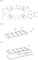
- the label 8 comprises a main face 10 intended to be turned facing light radiation.
- the label 8 comprises a flexible photovoltaic module 11 and a flexible printed circuit 12.
- the photovoltaic module 11 and the flexible printed circuit 12 are integral with each other. We can for example provide that they are both secured to a flexible housing 34 of the label 8, for example made of foam.
- the photovoltaic module 11 and the flexible printed circuit 12 are superimposed on one another.
- the photovoltaic module 11 is glued to the housing 34, and the flexible printed circuit 12 is sandwiched between these two components.
- the flexible photovoltaic module 11 comprises one or more photovoltaic cells 13.
- organic photovoltaic cells are provided, also designated by the acronym “OPV”.
- These photovoltaic cells 13 comprise a layer of material transforming the incident light radiation into electricity, a series of first electrodes on a first face, for example the main face 10 of the label 8, and a series of second electrodes on a second face 16 opposite the first face 10.
- the series of first electrodes is electrically connected to a first electrical contact 17, and the series of second electrodes is electrically connected to a second contact 18.
- the flexible printed circuit 12 comprises a flexible insulating substrate 19 carrying electronic components 20.
- the substrate 19 comprises a first face 21 and a second face 22 opposite the first face 21. In the example presented, the second face 22 is turned to opposite the photovoltaic module, and carries the electronic components 20.
- the electronic components 20 are thus arranged between the housing 34 and the flexible substrate 19, and are thus protected.
- the substrate 19 also carries electronic tracks for the electrical connection of the electronic components 20.
- the flexible printed circuit 12 comprises a first electrical contact 23 intended to be electrically connected to the first electrical contact 17 of the module photovoltaic 11. This electrical connection is made for example via an electric wire 24 or a conductive ribbon.
- the flexible printed circuit 12 comprises a second electrical contact 25 intended to be electrically connected to the second electrical contact 18 of the photovoltaic module 11.
- This electrical connection is made for example by means of an electrically conductive glue, if the electrical contacts 18 and 25 are juxtaposed.
- the electronic components 20 are arranged on the face 21 of the flexible printed circuit 12 facing the photovoltaic module 11. It is then possible to provide a layer of foam interposed between the flexible printed circuit 12 and the photovoltaic module 11.
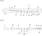
- the flexible printed circuit 12 carries an electronic circuit which comprises a load 29 comprising at least one processor 26 and a communication module 27 adapted to communicate by radio waves with the second communication module 9 of the anchors 5.
- the load 29 can also include a sensor (not shown). It can for example be an ambient temperature sensor.
- the load 29 may also include one or more light-emitting diodes (LEDs).
- the communication module 27 includes an antenna 36 drawn on the flexible printed circuit 12.
- the load 29 is dimensioned to consume a very low electrical intensity. For example, the average current consumed by the load is less than 10 micro-Amps ( ⁇ A).
- the average electrical intensity includes episodes of peak consumption and episodes of very low consumption. Peak consumption episodes are spaced out over time.
- the duty cycle of load 29, from active time duration to operating period is less than 0.01.
- the electrical intensity consumed in the active period, corresponding to the emission of the signal is very low, for example less than 10 milliAmperes (mA).
- the communication module 27 of the label 8 and the second module communication 9 of the anchor 5 are complementary modules, allowing wireless communication, by radio waves, between these two modules.
- the load 29 of the electronic circuit carried by the flexible printed circuit 12 does not include a battery, nor is it connected to a battery nor to a charging connector capable of being connected to an external charger.
- the flexible printed circuit 12 is supplied with electrical energy by the photovoltaic module 11. More precisely, the photovoltaic module 11 charges a supercapacitor 30 which is used to power the load 29 (comprising at least the processor 26 and the communication module 27).
- the supercapacitor 30 is for example an electrochemical double layer capacitor (known by the acronym “EDLC” for “Electrochemical double layer capacitor”).
- EDLC electrochemical double layer capacitor
- This capacitor is for example another supercapacitor 30, or even, as shown, two other supercapacitors 30, or a capacitor having a low internal resistance. This makes it possible to reduce the equivalent resistance of this portion of the circuit, and therefore to reduce the risk that the input voltage of the downstream analog comparator circuit drops below V_UVLO-.
- An electronic protection circuit 37 is interposed between the photovoltaic module 11 and the supercapacitor 30 so as not to discharge the supercapacitor 30 towards the photovoltaic module 11 and to protect the photovoltaic module 11 when the voltage across the supercapacitor 30 is greater than the voltage delivered by the photovoltaic module 11.
- TRCB a circuit called “TRCB”, an acronym for the expression “True reverse current blocking”, for “True Reverse Current Blocking”, as for example described in US2013/063,116 , incorporated herein by reference in its entirety for any purpose.
- An analog comparator circuit 28 is interposed between the supercapacitor 30 and the load 29.
- the analog comparator circuit 28 is used to only allow the photovoltaic module 11 to power the load 29 if the voltage delivered is greater than a predetermined minimum threshold voltage V_UVLO+.
- the initial supply of energy to the load 29 in fact creates a demand for energy which causes the voltage delivered by the supercapacitor 30 to drop and, if this demand causes this voltage to drop to a value lower than a predetermined value V_UVLO-, the load 29 would no longer be powered correctly, and the load 29 cannot start correctly, and risks being damaged.
- the value of the predetermined minimum threshold voltage V_UVLO+ is such that the voltage drop due to the start of the load 29 does not cause the voltage delivered by the photovoltaic module 11 to drop below said predetermined value V_UVLO-.
- the supercapacitor 30 supplies the charge with an input voltage greater than V_UVLO-, as long as it is sufficiently charged.
- FIG. 6 thus illustrates a power cycle of the load during variation in ambient illumination.
- the photovoltaic module 11 charges the supercapacitor 30, and the voltage across the latter increases until it reaches the voltage V_UVLO+ .
- This step can typically last at least 15 minutes, especially in the case of a sunrise.
- the analog comparator circuit 28 detects that the voltage Vin is greater than V_UVLO+, and authorizes the power supply of the load 29, which allows it to start. Due to starting, the voltage Vin drops to a value V_Qinit greater than V_UVLO-. Load 29 then operates.
- the processor 26 commands the communication module 27 to transmit.
- the frequency of communications is for example of the order of one communication every second to one communication every hour, or even from one communication every second to one communication every minute.
- the communication module 27 communicates for example an identifier of the label 8. If the label 8 includes a sensor, the communication module 27 can also communicate the value of at least one recent measurement of the sensor.
- the second communication module 9 of an anchor 5 detects the transmitted signal. This is particularly the case if an anchor 5 is close to the label 8. If the system includes several anchors 5, it is possible that only some, or even only one, of the anchors 5 detect the signal emitted by the label 8.
- the light power arriving on the photovoltaic module is greater than a threshold power, and the load 29 is powered by the photovoltaic module 11.
- the available light power becomes lower than the threshold power. This is for example a sunset, an extinction of the light, or a masking of the photovoltaic module 11 (for example covered by an opaque object).
- the supercapacitor 30 then continues to power the load 29. As long as the voltage drops while remaining greater than V_UVLO-, the load 29 continues to be powered and to operate.
- the analog comparator circuit 28 detects that the voltage Vin is lower than V_UVLO-, and cuts the supply of the load 29.
- the analog comparator circuit 28 implements a hysteresis to compare the voltage Vin to a threshold voltage V_UVLO+ for the supply of the load 29 and to a threshold voltage V_UVLO- lower than V_UVLO+ , to cut off the power supply to the load 29.
- the load 29 is no longer powered and no longer operates. Despite everything, for example, the brightness remains sufficient for the supercapacitor 30 to continue to deliver a non-zero voltage.
- the supercapacitor 30 is sized according to environment 1, so that the cases where the voltage Vin becomes lower than V_UVLO- remain exceptional.
- a fifth phase P5 the photovoltaic module 11 receives light again.
- this light power is low, and lower than the power necessary for the operation of the load 29.
- the voltage Vin increases while remaining lower than V_UVLO+, and the load 29 remains off.
- the analog comparator circuit 28 detects that the voltage Vin is greater than V_UVLO+, and authorizes the supply of the load 29, which allows it to start. Due to starting, the voltage Vin drops to a value V_Qinit greater than V_UVLO-. Load 29 then operates, in this sixth phase P6.
- the voltage Vin drops, in this sixth phase P6, to V_UVLO-.
- the analog comparator circuit 28 detects that the voltage Vin is lower than V_UVLO-, and cuts off the power supply to the load 29.
- the processor 26 can be programmed to control the power supply of one or more LEDs of the label according to certain predefined conditions. For example, if sufficient energy is available, the processor 26 controls the lighting of an LED, for example periodically.
- the processor 26 is programmed to implement processing according to a power supply parameter.
- the power supply parameter is for example a value of the voltage delivered by the photovoltaic module 11, which can be supplied as an analog input to the processor 26.
- the processor 26 can implement the one and/or the other of the functions below.
- the processor 26 can modify the communication frequency of the communication module 27, for example spacing out the communications if the power parameter is representative of a drop in power.
- the processor 26 can modify the nature of the information communicated, for example reducing the information communicated to the strict minimum (the label identifier) if the power parameter is representative of a drop in power.
- the processor 26 can modify the activation parameters of a light-emitting diode, for example triggering the power supply of a light-emitting diode if the power parameter is representative of a drop in power.
- the processor 26 can modify the operation of the electronic components, for example interrupting the power supply to a sensor if the power parameter is representative of a drop in power supply.
- Label 8 is therefore not very sensitive to variations in illumination in the environment (day/night or summer/winter alternation, cloudy periods, complementary use or not of artificial lighting, frequency of use and nature thereof, distance from the label to light sources, etc.).
- the electronic circuit carried by the flexible printed circuit 12 comprises an electronic safety component 38 adapted to limit the output voltage of the photovoltaic module 11 applied to the supercapacitor 30.
- the electronic circuit carried by the flexible printed circuit 12 comprises a solid state battery mounted on the surface, upstream of the supercapacitor 30.
- the electronic circuit carried by the flexible printed circuit 12 comprises a passive component 39 between the analog comparator circuit 28 and the load 29.
- This passive component 39 of the diode type for example, makes it possible to prevent an uncontrolled low voltage from power the load 29, outside the operating ranges.
- the anchors 5 communicate to the processor 6, via their communication module, the signals that they have received from the labels 8 and the identifiers thereof.
- the processor 6 determines the position of a label 8 from the known position of an anchor 5 or the anchors 5 having detected it.
- the system described above can be used in an environment 1 in which it is desired to regularly determine the position of objects 2.
- an object 2 is attached to a label 8.
- the face of the label 8 comprising the photovoltaic module 11 remains facing accessible to ambient light during this attachment.
- object 2 is placed in a tray, and label 8 is secured to the tray.
- the pocket is for example fixed on the exterior face of the side of the tray, thus allowing the trays to be stacked while allowing the labels 8 access to the light.
- the label 8 may include an adhesive face (the face opposite the face 10) which can be secured by gluing to the object 2 or an object secured thereto.
- the label 8 can then include a peelable film (not shown) which is removed before securing by gluing to the object 2.
- the flexibility of the label 8 makes it possible to stick it on a non-flat and/or rough surface of object 2, and therefore adapt for different uses.
- the processor 6 includes a computerized control module adapted to control the labels 8 present in the environment 1.
- the computerized control module accesses a checklist of the identifiers of labels 8 entered by an operator, and likely to be present in the environment, and compares with the identifiers of the labels 8 whose position has been determined for a predetermined prior period of time. If the computerized control module determines that the position of a label 8 of the checklist has not been determined, this may mean that the label 8 is, unexpectedly, outside of environment 1 or more powered by solar energy. The computerized control module can then emit a signal or an alarm notification comprising at least the identifier of this label 8.
- the notification can include the last position determined for the label 8.
- object 2 when object 2 enters the environment, we associate it with a label 8, and we add label 8 to the identifier checklist.
- object 2 leaves the environment we deassociate it from label 8, and we remove it from the list of identifiers.
- the computerized control module compares the route of a label with a route programmed for this label.
- a programmed route includes a maximum duration spent by a label in a position. From a plurality of position detections of a label 8, the computerized control module determines the route of the label, and compares it with the programmed route. If there is a difference between the detected route and the programmed route, an alarm signal or notification may be issued. This notification may include the position of a label concerned, or even its identifier.
- an alarm can be issued with the identified position.
Landscapes
- Engineering & Computer Science (AREA)
- Computer Hardware Design (AREA)
- Microelectronics & Electronic Packaging (AREA)
- Physics & Mathematics (AREA)
- General Physics & Mathematics (AREA)
- Theoretical Computer Science (AREA)
- Life Sciences & Earth Sciences (AREA)
- Sustainable Development (AREA)
- Sustainable Energy (AREA)
- Photovoltaic Devices (AREA)
- Radar Systems Or Details Thereof (AREA)
- Details Of Aerials (AREA)
Applications Claiming Priority (1)
| Application Number | Priority Date | Filing Date | Title |
|---|---|---|---|
| FR2214093A FR3144355B1 (fr) | 2022-12-21 | 2022-12-21 | Système de localisation d’étiquettes |
Publications (3)
| Publication Number | Publication Date |
|---|---|
| EP4390761A1 true EP4390761A1 (de) | 2024-06-26 |
| EP4390761C0 EP4390761C0 (de) | 2025-11-05 |
| EP4390761B1 EP4390761B1 (de) | 2025-11-05 |
Family
ID=85570165
Family Applications (1)
| Application Number | Title | Priority Date | Filing Date |
|---|---|---|---|
| EP23218766.6A Active EP4390761B1 (de) | 2022-12-21 | 2023-12-20 | Etikettenlokalisierungssystem |
Country Status (2)
| Country | Link |
|---|---|
| EP (1) | EP4390761B1 (de) |
| FR (1) | FR3144355B1 (de) |
Citations (5)
| Publication number | Priority date | Publication date | Assignee | Title |
|---|---|---|---|---|
| US20050148121A1 (en) * | 2003-12-19 | 2005-07-07 | Shunpei Yamazaki | Manufacturing method of thin film integrated circuit device and manufacturing method of non-contact type thin film integrated circuit device |
| US20130063116A1 (en) | 2011-09-14 | 2013-03-14 | Fairchild Semiconductor Corporation | True reverse current blocking system |
| WO2015136146A1 (en) * | 2014-03-11 | 2015-09-17 | Mariella Labels Oy | Electronic price label and electronic price label system |
| CN110070166A (zh) * | 2019-04-19 | 2019-07-30 | 中国科学院上海高等研究院 | 提高超高频rfid标签芯片最大工作场强的电路及方法 |
| US11232390B1 (en) * | 2021-06-29 | 2022-01-25 | Ferret Systems Inc. | Item tracking system with electronic tracking labels containing sensors |
-
2022
- 2022-12-21 FR FR2214093A patent/FR3144355B1/fr active Active
-
2023
- 2023-12-20 EP EP23218766.6A patent/EP4390761B1/de active Active
Patent Citations (5)
| Publication number | Priority date | Publication date | Assignee | Title |
|---|---|---|---|---|
| US20050148121A1 (en) * | 2003-12-19 | 2005-07-07 | Shunpei Yamazaki | Manufacturing method of thin film integrated circuit device and manufacturing method of non-contact type thin film integrated circuit device |
| US20130063116A1 (en) | 2011-09-14 | 2013-03-14 | Fairchild Semiconductor Corporation | True reverse current blocking system |
| WO2015136146A1 (en) * | 2014-03-11 | 2015-09-17 | Mariella Labels Oy | Electronic price label and electronic price label system |
| CN110070166A (zh) * | 2019-04-19 | 2019-07-30 | 中国科学院上海高等研究院 | 提高超高频rfid标签芯片最大工作场强的电路及方法 |
| US11232390B1 (en) * | 2021-06-29 | 2022-01-25 | Ferret Systems Inc. | Item tracking system with electronic tracking labels containing sensors |
Also Published As
| Publication number | Publication date |
|---|---|
| EP4390761C0 (de) | 2025-11-05 |
| FR3144355B1 (fr) | 2024-11-22 |
| EP4390761B1 (de) | 2025-11-05 |
| FR3144355A1 (fr) | 2024-06-28 |
Similar Documents
| Publication | Publication Date | Title |
|---|---|---|
| WO1993021614A1 (fr) | Systeme de surveillance d'un objet meuble ou mobile | |
| EP4390761B1 (de) | Etikettenlokalisierungssystem | |
| EP3896469B1 (de) | Isolator für elektrische hochspannungsleitungen mit einer leckstrommesseinrichtung mit verlängerter reichweite | |
| EP3649732A1 (de) | Vorrichtung zum testen einer satellitensolaranordnung | |
| EP2977286A1 (de) | Kabeltransportausrüstung | |
| EP0393774B1 (de) | Überwachungsschaltung und mit einer solchen Schaltung ausgerüstete Datenübertragungseinrichtung | |
| EP2036128B1 (de) | Anzeigevorrichtung und ihre verwendung | |
| EP0265328A1 (de) | Autonomes Stromversorgungssystem | |
| EP3190681A1 (de) | Verfahren und vorrichtung zum aufladen einer batterie | |
| EP2544345A1 (de) | Spannungsverstärkungsschaltkreis | |
| FR2725084A1 (fr) | Alimentation electrique autonome | |
| EP2584873B1 (de) | Drahtlose Erkennungsvorrichtung | |
| FR2945072A1 (fr) | Systeme d'occultation energetiquement multifonctionnel | |
| EP4111851B1 (de) | Verfahren und agrivoltaik-vorrichtung zum schutz einer pflanze vor frost | |
| FR3024617A1 (fr) | Module photoactif plurifonctionnel integre dans un ecran d'un appareil eletronique et son organe de gestion | |
| EP4390565A1 (de) | Vorrichtung zur übertragung einer nachricht von einer armbanduhr | |
| FR3017974A1 (fr) | Dispositif d'interconnexion et de gestion d'elements photovoltaiques | |
| FR2944143A1 (fr) | Detection de salissure | |
| EP2540569A1 (de) | Betriebsverfahren einer Signalisierungsvorrichtung eines Kraftfahrzeugs | |
| CH720368A2 (fr) | Cadran de montre comprenant un dispositif autonome de transmission d'un message | |
| EP1494489A1 (de) | Funkkommunikationsvorrichtung mit mindestens einer durch ein Digitalsignal kontrollierten Lichtquelle | |
| FR3107942A1 (fr) | Procédé de gestion d’un éclairage et éclairage correspondant | |
| WO2004105211A1 (fr) | Dispositif comprenant un appareil domotique muni d'un panneau photovoltaique | |
| WO2026068476A1 (fr) | Systeme de gestion d'un pack batterie pour l'alimentation d'un actionneur en veille | |
| FR2868660A1 (fr) | Procede de pilotage d'un dispositif d'eclairage a duree et puissance ajustables et dispositif associe |
Legal Events
| Date | Code | Title | Description |
|---|---|---|---|
| PUAI | Public reference made under article 153(3) epc to a published international application that has entered the european phase |
Free format text: ORIGINAL CODE: 0009012 |
|
| STAA | Information on the status of an ep patent application or granted ep patent |
Free format text: STATUS: THE APPLICATION HAS BEEN PUBLISHED |
|
| AK | Designated contracting states |
Kind code of ref document: A1 Designated state(s): AL AT BE BG CH CY CZ DE DK EE ES FI FR GB GR HR HU IE IS IT LI LT LU LV MC ME MK MT NL NO PL PT RO RS SE SI SK SM TR |
|
| STAA | Information on the status of an ep patent application or granted ep patent |
Free format text: STATUS: REQUEST FOR EXAMINATION WAS MADE |
|
| 17P | Request for examination filed |
Effective date: 20241215 |
|
| GRAP | Despatch of communication of intention to grant a patent |
Free format text: ORIGINAL CODE: EPIDOSNIGR1 |
|
| STAA | Information on the status of an ep patent application or granted ep patent |
Free format text: STATUS: GRANT OF PATENT IS INTENDED |
|
| INTG | Intention to grant announced |
Effective date: 20250617 |
|
| RIC1 | Information provided on ipc code assigned before grant |
Ipc: G06K 19/07 20060101AFI20250606BHEP Ipc: G06K 19/077 20060101ALI20250606BHEP |
|
| GRAS | Grant fee paid |
Free format text: ORIGINAL CODE: EPIDOSNIGR3 |
|
| GRAA | (expected) grant |
Free format text: ORIGINAL CODE: 0009210 |
|
| STAA | Information on the status of an ep patent application or granted ep patent |
Free format text: STATUS: THE PATENT HAS BEEN GRANTED |
|
| AK | Designated contracting states |
Kind code of ref document: B1 Designated state(s): AL AT BE BG CH CY CZ DE DK EE ES FI FR GB GR HR HU IE IS IT LI LT LU LV MC ME MK MT NL NO PL PT RO RS SE SI SK SM TR |
|
| REG | Reference to a national code |
Ref country code: CH Ref legal event code: F10 Free format text: ST27 STATUS EVENT CODE: U-0-0-F10-F00 (AS PROVIDED BY THE NATIONAL OFFICE) Effective date: 20251105 Ref country code: GB Ref legal event code: FG4D Free format text: NOT ENGLISH |
|
| REG | Reference to a national code |
Ref country code: DE Ref legal event code: R096 Ref document number: 602023008304 Country of ref document: DE |
|
| REG | Reference to a national code |
Ref country code: IE Ref legal event code: FG4D Free format text: LANGUAGE OF EP DOCUMENT: FRENCH |
|
| U01 | Request for unitary effect filed |
Effective date: 20251126 |
|
| U07 | Unitary effect registered |
Designated state(s): AT BE BG DE DK EE FI FR IT LT LU LV MT NL PT RO SE SI Effective date: 20251204 |
|
| PGFP | Annual fee paid to national office [announced via postgrant information from national office to epo] |
Ref country code: AT Payment date: 20260113 Year of fee payment: 3 |
|
| U20 | Renewal fee for the european patent with unitary effect paid |
Year of fee payment: 3 Effective date: 20251223 |
|
| PG25 | Lapsed in a contracting state [announced via postgrant information from national office to epo] |
Ref country code: ES Free format text: LAPSE BECAUSE OF FAILURE TO SUBMIT A TRANSLATION OF THE DESCRIPTION OR TO PAY THE FEE WITHIN THE PRESCRIBED TIME-LIMIT Effective date: 20251105 |
|
| PG25 | Lapsed in a contracting state [announced via postgrant information from national office to epo] |
Ref country code: NO Free format text: LAPSE BECAUSE OF FAILURE TO SUBMIT A TRANSLATION OF THE DESCRIPTION OR TO PAY THE FEE WITHIN THE PRESCRIBED TIME-LIMIT Effective date: 20260205 |
|
| PGFP | Annual fee paid to national office [announced via postgrant information from national office to epo] |
Ref country code: IE Payment date: 20260330 Year of fee payment: 3 |
|
| PG25 | Lapsed in a contracting state [announced via postgrant information from national office to epo] |
Ref country code: HR Free format text: LAPSE BECAUSE OF FAILURE TO SUBMIT A TRANSLATION OF THE DESCRIPTION OR TO PAY THE FEE WITHIN THE PRESCRIBED TIME-LIMIT Effective date: 20251105 |
|
| PG25 | Lapsed in a contracting state [announced via postgrant information from national office to epo] |
Ref country code: RS Free format text: LAPSE BECAUSE OF FAILURE TO SUBMIT A TRANSLATION OF THE DESCRIPTION OR TO PAY THE FEE WITHIN THE PRESCRIBED TIME-LIMIT Effective date: 20260205 |
|
| PG25 | Lapsed in a contracting state [announced via postgrant information from national office to epo] |
Ref country code: IS Free format text: LAPSE BECAUSE OF FAILURE TO SUBMIT A TRANSLATION OF THE DESCRIPTION OR TO PAY THE FEE WITHIN THE PRESCRIBED TIME-LIMIT Effective date: 20260305 |
|
| PG25 | Lapsed in a contracting state [announced via postgrant information from national office to epo] |
Ref country code: PL Free format text: LAPSE BECAUSE OF FAILURE TO SUBMIT A TRANSLATION OF THE DESCRIPTION OR TO PAY THE FEE WITHIN THE PRESCRIBED TIME-LIMIT Effective date: 20251105 |