EP4391220A1 - Antennenanordnung und elektronische vorrichtung - Google Patents
Antennenanordnung und elektronische vorrichtung Download PDFInfo
- Publication number
- EP4391220A1 EP4391220A1 EP22866425.6A EP22866425A EP4391220A1 EP 4391220 A1 EP4391220 A1 EP 4391220A1 EP 22866425 A EP22866425 A EP 22866425A EP 4391220 A1 EP4391220 A1 EP 4391220A1
- Authority
- EP
- European Patent Office
- Prior art keywords
- antenna
- side frame
- gps
- lateral
- signal
- Prior art date
- Legal status (The legal status is an assumption and is not a legal conclusion. Google has not performed a legal analysis and makes no representation as to the accuracy of the status listed.)
- Pending
Links
Images


Classifications
-
- H—ELECTRICITY
- H01—ELECTRIC ELEMENTS
- H01Q—ANTENNAS, i.e. RADIO AERIALS
- H01Q21/00—Antenna arrays or systems
- H01Q21/28—Combinations of substantially independent non-interacting antenna units or systems
-
- H—ELECTRICITY
- H01—ELECTRIC ELEMENTS
- H01Q—ANTENNAS, i.e. RADIO AERIALS
- H01Q1/00—Details of, or arrangements associated with, antennas
- H01Q1/12—Supports; Mounting means
- H01Q1/22—Supports; Mounting means by structural association with other equipment or articles
- H01Q1/24—Supports; Mounting means by structural association with other equipment or articles with receiving set
- H01Q1/241—Supports; Mounting means by structural association with other equipment or articles with receiving set used in mobile communications, e.g. GSM
- H01Q1/242—Supports; Mounting means by structural association with other equipment or articles with receiving set used in mobile communications, e.g. GSM specially adapted for hand-held use
- H01Q1/243—Supports; Mounting means by structural association with other equipment or articles with receiving set used in mobile communications, e.g. GSM specially adapted for hand-held use with built-in antennas
-
- H—ELECTRICITY
- H01—ELECTRIC ELEMENTS
- H01Q—ANTENNAS, i.e. RADIO AERIALS
- H01Q1/00—Details of, or arrangements associated with, antennas
- H01Q1/12—Supports; Mounting means
- H01Q1/22—Supports; Mounting means by structural association with other equipment or articles
-
- H—ELECTRICITY
- H01—ELECTRIC ELEMENTS
- H01Q—ANTENNAS, i.e. RADIO AERIALS
- H01Q1/00—Details of, or arrangements associated with, antennas
- H01Q1/12—Supports; Mounting means
- H01Q1/22—Supports; Mounting means by structural association with other equipment or articles
- H01Q1/24—Supports; Mounting means by structural association with other equipment or articles with receiving set
- H01Q1/241—Supports; Mounting means by structural association with other equipment or articles with receiving set used in mobile communications, e.g. GSM
-
- H—ELECTRICITY
- H01—ELECTRIC ELEMENTS
- H01Q—ANTENNAS, i.e. RADIO AERIALS
- H01Q1/00—Details of, or arrangements associated with, antennas
- H01Q1/44—Details of, or arrangements associated with, antennas using equipment having another main function to serve additionally as an antenna, e.g. means for giving an antenna an aesthetic aspect
-
- H—ELECTRICITY
- H01—ELECTRIC ELEMENTS
- H01Q—ANTENNAS, i.e. RADIO AERIALS
- H01Q1/00—Details of, or arrangements associated with, antennas
- H01Q1/48—Earthing means; Earth screens; Counterpoises
-
- H—ELECTRICITY
- H01—ELECTRIC ELEMENTS
- H01Q—ANTENNAS, i.e. RADIO AERIALS
- H01Q21/00—Antenna arrays or systems
-
- H—ELECTRICITY
- H01—ELECTRIC ELEMENTS
- H01Q—ANTENNAS, i.e. RADIO AERIALS
- H01Q21/00—Antenna arrays or systems
- H01Q21/29—Combinations of different interacting antenna units for giving a desired directional characteristic
-
- H—ELECTRICITY
- H01—ELECTRIC ELEMENTS
- H01Q—ANTENNAS, i.e. RADIO AERIALS
- H01Q21/00—Antenna arrays or systems
- H01Q21/30—Combinations of separate antenna units operating in different wavebands and connected to a common feeder system
-
- H—ELECTRICITY
- H01—ELECTRIC ELEMENTS
- H01Q—ANTENNAS, i.e. RADIO AERIALS
- H01Q23/00—Antennas with active circuits or circuit elements integrated within them or attached to them
-
- H—ELECTRICITY
- H01—ELECTRIC ELEMENTS
- H01Q—ANTENNAS, i.e. RADIO AERIALS
- H01Q5/00—Arrangements for simultaneous operation of antennas on two or more different wavebands, e.g. dual-band or multi-band arrangements
- H01Q5/30—Arrangements for providing operation on different wavebands
- H01Q5/307—Individual or coupled radiating elements, each element being fed in an unspecified way
-
- H—ELECTRICITY
- H01—ELECTRIC ELEMENTS
- H01Q—ANTENNAS, i.e. RADIO AERIALS
- H01Q9/00—Electrically-short antennas having dimensions not more than twice the operating wavelength and consisting of conductive active radiating elements
- H01Q9/04—Resonant antennas
- H01Q9/0407—Substantially flat resonant element parallel to ground plane, e.g. patch antenna
- H01Q9/0421—Substantially flat resonant element parallel to ground plane, e.g. patch antenna with a shorting wall or a shorting pin at one end of the element
-
- H—ELECTRICITY
- H01—ELECTRIC ELEMENTS
- H01Q—ANTENNAS, i.e. RADIO AERIALS
- H01Q9/00—Electrically-short antennas having dimensions not more than twice the operating wavelength and consisting of conductive active radiating elements
- H01Q9/04—Resonant antennas
- H01Q9/30—Resonant antennas with feed to end of elongated active element, e.g. unipole
- H01Q9/42—Resonant antennas with feed to end of elongated active element, e.g. unipole with folded element, the folded parts being spaced apart a small fraction of the operating wavelength
Definitions
- the present disclosure relates to the technical field of antennas, and in particular to an antenna assembly and an electronic device.
- GPS global positioning system
- a dual-band GPS antenna (for example, involving a GPS L1 antenna and a GPS L5 antenna) is generally used for the positioning.
- one antenna is generally shared by both a L1 frequency band and a L5 frequency band.
- performance of the L1 antenna and performance of L5 antenna cannot be considered simultaneously, thereby greatly affecting the positioning accuracy.
- Embodiments of the present disclosure provide an antenna assembly and an electronic device.
- the embodiments of the present disclosure provide an antenna assembly.
- the antenna assembly includes a housing, a radio frequency circuit, a first antenna, a second antenna and a third antenna, where the first antenna, the second antenna and the third antenna are provided on the housing.
- the first antenna is configured to radiate a first radio frequency signal at a GPS L1 frequency band
- each of the second antenna and the third antenna is configured to radiate a second radio frequency signal at a GPS L5 frequency band.
- the radio frequency circuit includes a first GPS module and a second GPS module.
- the first GPS module is connected with the first antenna, and configured to support receipt and transmission of the first radio frequency signal.
- the second GPS module is switchable between being connected to the second antenna and being connected to the third antenna, and is configured to determine a target antenna based on network information of a received second radio frequency signal, and control a radio frequency path between the target antenna and the second GPS module to be turned on, where the target antenna is one of the second antenna and the third antenna.
- the embodiments of the present disclosure provide an electronic device, and the electronic device includes the foregoing antenna assembly.
- a housing, a radio frequency circuit, a first antenna, a second antenna and a third antenna are included, where the first antenna, the second antenna and the third antenna are provided on the housing.
- the first antenna is configured to radiate a first radio frequency signal at a GPS L1 frequency band
- each of the second antenna and the third antenna is configured to radiate a second radio frequency signal at a GPS L5 frequency band.
- the radio frequency circuit includes a first GPS module and a second GPS module. The first GPS module is connected with the first antenna and configured to support receipt and transmission of the first radio frequency signal.
- the second GPS module is switchable between being connected to the second antenna and being connected to the third antenna, and is configured to determine a target antenna based on network information of a received second radio frequency signal, and control a radio frequency path between the target antenna and the second GPS module to be switched on.
- GPS antennas of two frequency bands are used in the antenna assembly, in which the first antenna is assisted by the second antenna and the third antenna, and the positioning accuracy can be improved.
- two GPS L5 antennas each configured to radiate a signal at the GPS L5 frequency band are provided, this can avoid a case in the related art that the GPS L5 antenna fails to work when the user holds the electronic device, and can effectively increase the radiation efficiency of the GPS L5 antenna. Therefore, the GPS positioning accuracy of the antenna assembly and the electronic device can be improved.
- orientational or positional relationship indicated by terms such as “center”, “longitudinal”, “transverse”, “length”, “width”, “thickness”, “upper”, “lower”, “front”, “rear”, “left”, “right”, “top”, “bottom”, “axial”, “radial”, and “circumferential”, are based on orientational or positional relationship illustrated in the drawings, which is merely for the purpose of ease of describing the present disclosure and simplifying the description, and itis not intended to indicate or imply that the device or element referred to must have a specific orientation, or be constructed and operated in the specific orientation, therefore it cannot be understood as a limitation on the present disclosure.
- first, second are merely for a descriptive purpose and cannot be understood as indicating or implying relative importance or implicitly indicating the number of technical features indicated.
- a feature defined by “first”, or “second” may explicitly or implicitly indicate that at least one such feature is included.
- a plurality of means at least two, for example, two, three, or more, unless otherwise specified specifically.
- a first feature is “above” or “below” a second feature may be a case that the first feature is in direct contact with the second feature, or the first feature and the second feature are in indirect contact through an intermediate medium.
- the first feature being “on”, “over”, and “above” the second feature may mean that the first feature is directly above or diagonally above the second feature, or merely indicate that level height of the first feature is higher than the level height of the second feature.
- the first feature being “under”, “below” and “beneath” the second feature may mean that the first feature is directly below or diagonally below the second feature, or merely represents that level height of the first feature is less than the level height of the second feature.
- the antenna assembly in the embodiments of the present disclosure may be applied to an electronic device having a wireless communication function, and the electronic device may be a handheld device, a vehicle-mounted device, a wearable device, a computing device, or other processing device connected to a wireless modem, and various user equipment (UE) (for example, a mobile phone), a mobile station (MS), and the like.
- UE user equipment
- MS mobile station
- the above-mentioned devices are all referred to as an electronic device.
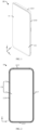
- the electronic device includes a display screen assembly 11 and a housing 12.
- the housing 12 includes a frame 121 and a rear cover 123.
- the display screen assembly 11 includes a display screen 111.
- the display screen 111 may be an organic light-emitting diode (OLED) screen, or a liquid crystal display (LCD) screen.
- the display screen 11 may be configured to display information and provide an interactive interface for a user.
- the display screen 111 may be in a rectangle shape or an arc-angle rectangle shape, and the arc-angle rectangle may sometimes be referred to as a rounded rectangle, that is, four corners of a rectangle each are of an arc for transition, and the four sides of the rectangle are generally straight segments.
- the frame 121 may be made of a metal material such as an aluminum alloy, a magnesium alloy or stainless steel, or may be made of an insulating material such as plastic.
- the frame 121 is provided on a periphery of the display screen assembly 11 for supporting and protecting the display screen assembly 11.
- the display screen assembly 11 may be fixedly connected with the frame 121 through for example a dispensing process.
- the frame 121 may further extend towards the interior of the electronic device to form a middle plate, and the middle plate and the frame 121 which are integrally formed are referred to as a middle frame.
- the display screen assembly 11 may be fixedly connected with the frame 121 or the middle plate through for example the dispensing process. As illustrated in FIG.
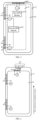
- the frame 121 is substantially rectangular, and the frame 121 includes a top-side frame 1213, a bottom-side frame 1215, a first lateral-side frame 1217 and a second lateral-side frame 1219. Both the first lateral-side frame 1217 and the second lateral-side frame 1219 are connected between the top-side frame 1213 and the bottom-side frame 1215. The first lateral-side frame 1217 and the second lateral-side frame 1219 are provided opposite to each other.
- the top-side frame 1213, the first lateral-side frame 1217, the bottom-side frame 1215, and the second lateral-side frame 1219 are sequentially connected end to end, and provided at the periphery of the middle plate.
- the various side frames may be in a right-angle connection or an arc-shaped transition connection.
- a plurality of metal frame antennas may be provided in the frame 121.
- the metal frame antennas may be defined by a slit(s) provided on the frame.
- the rear cover 123 is provided on a side of the display screen 111 that faces away from a display area of the display screen 111, and is connected with the frame 121. Further, the display screen assembly 11 and the rear cover 123 are located on opposite sides of the middle plate, respectively.
- the rear cover 123 may be made of a metal material such as an aluminum alloy, a magnesium alloy or stainless steel, or may be made of an insulating material, such as plastic, glass, ceramic, leather, denim, or bamboo. Further, the rear cover 123 is connected with the frame 121 to define an accommodating cavity, which is a mounting space, for mounting electronic components such as a battery, a motherboard, and a camera module of the electronic device. As illustrated in FIG. 3 , electronic components, such as a processor, a storage unit, a power management module, a baseband chip, a camera, a sensor, and a receiver, of the electronic device are integrated on a main board 14.
- the main board 14 is provided on the side of the display screen 111 that faces away from the display area, and the main board 14 may be fixedly connected to the frame through a structural member such as a screw.
- the main board 14 may be a printed circuit board (PCB) or a flexible printed circuit (FPC).
- a part of a radio frequency circuit for processing radio frequency signals may be integrated on the substrate, and a controller capable of controlling operation of the electronic device and the like may also be integrated on the main board.
- the radio frequency circuit includes, but is not limited to, an antenna assembly, at least one amplifier, a transceiver, a coupler, a low noise amplifier (LNA), a duplexer, and the like.
- the radio frequency circuit may further communicate with a network and other devices through wireless communication.
- the wireless communication may use any communication standard or protocol, including but not limited to Global System for Mobile communication (GSM), General Packet Radio Service (GPRS), Code Division Multiple Access (CDMA), Wideband Code Division Multiple Access (WCDMA), Long Term Evolution (LTE), Global Positioning System (GPS), email, Short Messaging Service (SMS), and the like.
- GSM Global System for Mobile communication
- GPRS General Packet Radio Service
- CDMA Code Division Multiple Access
- WCDMA Wideband Code Division Multiple Access
- LTE Long Term Evolution
- GPS Global Positioning System
- email Short Messaging Service
- the embodiments of the present disclosure provide an antenna assembly, and the antenna assembly may include the foregoing housing 12, a radio frequency circuit 15, and a plurality of antennas provided on the housing 12.
- the antennas provided on the housing 12 may include at least a first antenna 161 for radiating a first radio frequency signal at a GPS L1 frequency band, and a plurality of antennas for radiating a second radio frequency signal at a GPS L5 frequency band, for example, a second antenna 162 and a third antenna 163.
- the first antenna 161 may be referred to as a GPS L1 antenna
- each of the second antenna 162 and the third antenna 163 may be referred to as a GPS L5 antenna.
- Each of the first antenna 161, the second antenna 162, and the third antenna 163 may be one of a metal frame antenna, an FPC antenna, and an LDS antenna.
- the FPC antenna refers to a radiator provided on the FPC, and the FPC antenna may be fixed on a non-appearance surface of the rear cover 123 through for example bonding, embedding, or welding.
- the LDS antenna refers to a radiator that is directly plated, through a laser technology, on the non-appearance surface of the rear cover 123 made of an insulating material.
- the radio frequency circuit 15 may include a first GPS module 151 and a second GPS module 152.
- the first GPS module 151 is connected with the first antenna 161, and may be configured to support control over receipt and transmission of the first radio frequency signal at the GPS L1 frequency band.
- the first GPS module 151 includes, but is not limited to, a power amplifier, a filter, a low noise amplifier, a radio frequency switch, and the like.
- the second GPS module 152 is switchable between being connected to the second antenna 162 and being connected to the third antenna 163.
- a target antenna may be determined based on network information of the received second radio frequency signal, and a radio frequency path between the target antenna and the second GPS module 152 may be controlled to be switched on, where the target antenna is one of the second antenna 162 and the third antenna 163.
- the network information may include original and processed information associated with the wireless performance metrics of the received antenna signal, such as received power, transmitted power, reference signal received power (RSRP), reference signal received quality (RSRQ), received signal strength indication (RSSI), signal to noise ratio (SNR), rank of a MIMO channel matrix, carrier to interference plus noise ratio (RS-CINR), frame error rate, bit error rate, channel quality measurements based on signal quality data (such as Ec/lo or c/No data), information regarding to whether a response (reply) corresponding to a request from a mobile terminal is being received from a base station, information regarding to whether a network access procedure is successful, and so on.
- RSRP reference signal received power
- RSSI received signal strength indication
- SNR signal to noise ratio
- rank of a MIMO channel matrix such as Ec/lo or c/No data
- RS-CINR carrier to interference plus noise ratio
- the network information is received signal strength indication.
- the second GPS module 152 may measure the received signal strength indication of the second radio frequency signal received by the second antenna 162, and compare the received signal strength indication with a preset value. If the received signal strength indication is lower than the preset value, it may be determined that the second antenna 162 is blocked.
- the third antenna 163 may be recognized as the target antenna, and a radio frequency path between the second GPS module 152 and the third antenna 163 may be controlled to be switched on, and then the unblocked third antenna 163 is used to receive and transmit the second radio frequency signal at the GPS L5 frequency band, so as to improve the performance of the second radio frequency signal at the GPS L5 frequency band.
- the antenna assembly includes the first antenna 161 for radiating a signal at the GPS L1 frequency band (1575MHz), as well as the second antenna 162 and the third antenna 163 each for radiating a signal at the GPS L5 frequency band (1175MHz).
- GPS antennas of two frequency bands are used in the antenna assembly, in which the first antenna 161 is assisted by the second antenna 162 and the third antenna 163, and the positioning accuracy can be improved.
- two GPS L5 antennas each configured to radiate a signal at the GPS L5 frequency band are provided, this can avoid a case in the related technology that the GPS L5 antenna fails to work when the user holds the electronic device, and can effectively increase the radiation efficiency of the GPS L5 antenna. Therefore, the GPS positioning accuracy of the antenna assembly can be improved.
- the rear cover 123 is an insulating rear cover, for example, the rear cover 123 is made of a plastic material, a ceramic material, a glass material, a leather material, or the like.
- the first antenna 161 is an FPC antenna attached onto the non-appearance surface of the rear cover 123, or is an LDS antenna provided on the non-appearance surface of the rear cover 123 through a laser technology.
- the first antenna 161 is provided close to the top-side frame 1213.
- the FPC antenna and the LDS antenna are simple in arrangement and convenient to install.
- the radiator of the first antenna 161 may be in a straight shape, a bent shape or a curved shape, and the curved shape may include at least a spiral shape, an S shape, a W shape, or the like.
- the radiator of the first antenna 161 includes a first radiating portion 1611, a second radiating portion 1612 and a third radiating portion 1613 that are sequentially connected, where each of the first radiating portion 1611 and the third radiating portion 1613 is provided in parallel to the top-side frame.
- the second radiating portion 1612 is connected with each of the first radiating portion 1611 and the third radiating portion 1613.
- the second radiating portion 1612 may be connected to any position of the third radiating portion 1613 and the first radiating portion 1611.
- the second radiating portion 1612 may be connected to any one end of the third radiating portion 1613, and the second radiating portion 1612 may be connected to any one end of the first radiating portion 1611.
- the second radiating portion 1612 is connected to one end of the first radiating portion 1611 and one end of the third radiating portion 1613, and the second radiating portion 1612 may be perpendicular to the first radiating portion 1611 and the third radiating portion 1613.
- the third radiating portion 1613 is provided close to the top-side frame, and the first radiating portion 1611 is provided thereon with a first feeding point S 1 and a first grounding point G1 that is grounded.
- the first feeding point S1 may be connected with the first GPS module 151, and configured to receive a first feeding current output by the first GPS module 151; and the first feeding current is fed to the first radiating portion 1611 through the first feeding point S 1. Since the first feeding point S1 is provided on the first radiating portion 1611 that is away from the top-side frame, the radiation current of the first antenna 161 flows in a direction from the bottom-side frame to the top-side frame, that is, the radiation current of the first antenna 161 flows upward, and there is a good upward radiation effect.
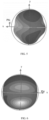
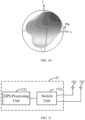
- the free space efficiency and the upper hemisphere efficiency of the first antenna 161 are illustrated in Table 1, and a perspective view illustrating the three-dimensional radiation of the first antenna 161 is presented in FIG. 5 and FIG. 6 .
- Table 1 the free space efficiency and the upper hemisphere efficiency of the first antenna 161 radiating a signal at a preset frequency.
- the free space efficiency of the first antenna 161 is -4.5 dB
- the upper hemisphere efficiency thereof is -7.5 dB
- the upper hemisphere efficiency accounts for 50%.
- the satellite is located on space, and by improving the upper hemisphere radiation efficiency of the GPS L1 antenna, and the upper hemisphere directivity of the GPS L1 antenna can be improved.
- the satellite transmits a signal When the satellite transmits a signal, the signal is transmitted in space and is interfered by various other scene signals; the signal of the antenna assembly corresponds to the signal of satellite, and the GPS L1 antenna (a directional antenna, whose beam points upward) having good upper hemisphere directivity enables the signal reception capability to be significantly improved, in which the energy is concentrated on the upper hemisphere and a strong anti-interference capability is enabled. Therefore, the positioning quality obtained by searching a satellite is greatly improved.
- two GPS L5 antennas are provided to assist the GPS L1 antenna, and the GPS positioning accuracy of the electronic device can be improved.
- the shape of the radiator of the first antenna 161 is not limited to the above illustration, and it may also be other shapes.
- the parallel arrangement may mean that an angle between the first radiating portion 1611 and the third radiating portion 1613 is less than or equal to 5 degrees, and the perpendicular arrangement may mean that an angle between the first radiating portion 1611 and the second radiating portion 1612 is within a preset range, for example, between 85 degrees and 95 degrees.
- the first antenna 161 may also be a metal frame antenna, that is, the first antenna 161 may be the metal frame antenna provided on the top-side frame 1213.
- the top-side frame 1213 is provided with a slit(s) 1211 to divide the top-side frame 1213 into a plurality of top conductive branches.
- the first antenna 161 is provided on at least one of the top conductive branches, and a first feeding point configured to be connected with a feeding source and a first grounding point configured to be grounded are also provided on this top conductive branch.
- the first feeding point may be connected with the first GPS module 151 and configured to receive a first feeding current output by the first GPS module 151; and the first feeding current is fed to the top conductive branch through the first feeding point, so that the top conductive branch may radiate the first radio frequency signal.
- a specific structure of the first antenna 161 is not limited to the foregoing illustration, and it may also be an antenna of other types.
- the second antenna 162 is provided on the first lateral-side frame 1217 or the second lateral-side frame 1219 at a position close to the top-side frame 1213
- the third antenna 163 is provided on the first lateral-side frame 1217or the second lateral-side frame 1219 at a position close to the bottom-side frame 1215.
- the radiation current of the second antenna 162 and the radiation current of the third antenna 163 all flow in the direction from the bottom-side frame to the top-side frame.
- the position of the lateral-side frame close to the top-side frame 1213 may be understood as an upper half part of the lateral-side frame of the electronic device, and the position of the lateral-side frame close to the bottom-side frame may be understood as a lower half part of the lateral-side frame of the electronic device. That is, the second antenna 162 may be provided on the upper half part of the lateral-side frame of the electronic device, and the third antenna 163 may be provided on the lower half part of the lateral-side frame of the electronic device. The second antenna 162 and the third antenna 163 may be provided on a same lateral-side frame of the electronic device, or may be provided on different lateral-side frames.
- a slit 1211 may be provided in the lateral-side frame, so that the lateral-side frame may be divided into the upper half part of the lateral-side frame and the lower half part of the lateral-side frame.
- the slit 1211 may be provided in an intermediate region of the first lateral-side frame 1217, or in an intermediate region of the second lateral-side frame 1219.
- the intermediate region of the first lateral-side frame 1217 may be understood as a region of the first lateral-side frame 1217 that is at a distance of 1/3 to 2/3 from the top-side frame.
- the intermediate region of the second lateral-side frame 1219 may be understood as a region of the second lateral-side frame 1219 that is at a distance of 1/3 to 2/3 from the top-side frame.
- the second antenna 162 is provided on the upper half part of the lateral-side frame of the electronic device and the third antenna 163 is provided on the lower half part of the lateral-side frame of the electronic device, that is, two GPS L5 antennas are respectively provided on the upper half part of the lateral-side frame and the lower half part of the lateral-side frame.
- the antenna assembly is applied to the electronic device, if the electronic device is hold in landscape, the second antenna 162 and the third antenna 163 are not completely blocked.
- the antenna assembly provided in the embodiments of the present disclosure can avoid a case in the related art that the GPS L5 antenna fails to work when the electronic device is hold by the user, and can effectively increase the upper hemisphere radiation efficiencies of the second antenna 162 and the third antenna 163, and then improve the GPS positioning accuracy of the antenna assembly.
- the frame is a conductive frame
- at least one of the first lateral-side frame 1217 and the second lateral-side frame 1219 is provided with slits 1211 to divide the metal frame into a plurality of side conductive branches.
- the second antenna is provided on a side conductive branch close to the top-side frame 1213
- the third antenna is provided on a side conductive branch close to the bottom-side frame.
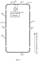
- three slits 1211 may be provided in the first lateral-side frame 1217, and they may divide the first lateral-side frame 1217 into four first side conductive branches.
- two first side conductive branches close to the top-side frame 1213 may use as the upper half part of the lateral-side frame of the electronic device
- two first side conductive branches close to the bottom-side frame may use as the lower half part of the lateral-side frame of the electronic device.
- four antennas may be provided on the four first side conductive branches respectively, which may be denoted as Ant1, Ant2, Ant3, and Ant4 respectively.
- the antenna Ant1 is a WiFi antenna for radiating a WiFi signal.
- the antenna Ant2 is a cellular antenna for radiating a 4G or 5G signal, or a GPS L5 antenna for radiating a signal at a GPS L5 frequency band.
- the antenna Ant3 is a cellular antenna for radiating a 4G or 5G signal, or a GPS L5 antenna for radiating a signal at the GPS L5 frequency band.
- the antenna Ant4 is a cellular antenna for radiating a 4G or 5G signal.
- Three slits 1211 may be provided on the second lateral-side frame 1219, and they may divide the second lateral-side frame 1219 into four second side conductive branches.
- two second side conductive branches close to the top-side frame 1213 may use as the upper half part of the lateral-side frame of the electronic device
- two second side conductive branches close to the bottom-side frame may use as the lower half part of the lateral-side frame of the electronic device.
- four antennas may be provided on the four conductive branches of the second lateral-side frame 1219 respectively, which may be denoted as Ant5, Ant6, Ant7, and Ant8 respectively.
- the antenna Ant5 is a cellular antenna for radiating a 4G or 5G signal.
- the antenna Ant6 is a cellular antenna for radiating a 4G or 5G signal, or a GPS L5 antenna for radiating a signal at the GPS L5 frequency band.
- the antenna Ant7 is a cellular antenna for radiating a 4G or 5G signal, or a GPS L5 antenna for radiating a signal at the GPS L5 frequency band.
- the antenna Ant8 is a cellular antenna for radiating a 4G or 5G signal.
- the network type of the radio frequency signal radiated by the antenna Ant2 is different from the network type of the radio frequency signal radiated by the antenna Ant6.
- the antenna Ant2 is a cellular antenna
- the antenna Ant6 is a GPS L5 antenna
- the antenna Ant2 is a GPS L5 antenna
- the antenna Ant6 is a cellular antenna
- the network type of the radio frequency signal radiated by the antenna Ant3 is different from the network type of the radio frequency signal radiated by the antenna Ant7.
- the conductive branch where the antenna Ant4 is located and the conductive branch where the antenna Ant8 is located may all extend along the bottom-side frame 1215, and are connected to be a whole body. That is, the cellular antennas Ant4 and Ant8 may be configured to radiate signals at the same frequency band. It is notable that, in the embodiments of the present disclosure, the frequency bands of the cellular signals radiated by the plurality of cellular antennas may be partially the same, or completely different. Exemplary, the cellular signals may include a low-frequency signal, a medium-high frequency signal, and a Sub-6G frequency band signal. The number of the cellular antennas is not limited to the above illustration, and in the embodiments of the present disclosure, the cellular antennas may further include a plurality of cellular antennas provided on the top-side frame 1213 and the bottom-side frame 1215.
- each side conductive branch may be provided thereon with a second feeding point S2 for feeding a current signal and a second grounding point G2 for being grounded, so that each side conductive branch may use as a radiator to radiate a radio frequency signal at a different frequency band.
- the side conductive branch where the second feeding point S2 is provided is configured to radiate a signal at the GPS L5 frequency band; if the second feeding point S2 is connected to the WiFi module, the side conductive branch where the second feeding point S2 is provided is configured to radiate a WiFi signal; and if the second feeding point S2 is connected to a cellular mobile module, the side conductive branch which the second feeding point S2 is provided is configured to radiate a cellular signal which is the 4G or 5G signal.
- the second feeding point S2 is provided on a side conductive branch close to the bottom-side frame 1215, and the second grounding point G2 is provided on the side conductive branch on a side of the second feeding point S2 away from the bottom-side frame 1215.
- a first side conductive branch it is illustrated by taking a first side conductive branch as an example, the second feeding point S2 on the first side conductive branch is connected with the second GPS module 152, that is, this first side conductive branch may be used as the radiator of the GPS L5 antenna.
- the slit 1211 for the radiator of the GPS L5 antenna is provided in the middle position of the first lateral-side frame 1217, and the opening of the slit 1211 is located above, that is, the slit 1211 is provided at a position above both the second feeding point S2 and the second grounding point G2.
- the slit 1211 is provided at a position above both the second feeding point S2 and the second grounding point G2. Therefore, the radiation current in the third antenna 163 flows upward, that is, the radiation current flows in a direction from the bottom-side frame 1215 to the top-side frame 1213, and the upward radiation effect is good.
- the free space efficiency and the upper hemisphere efficiency of the third antenna 163 are illustrated in Table 2, and a perspective view illustrating the three-dimensional radiation of the third antenna 163 is presented in FIG. 9 (where the third antenna 163 is provided on the first lateral-side frame 1217) and FIG. 10 (where the third antenna 163 is provided on the second lateral-side frame 1219).
- Table 2 the free space efficiency and the upper hemisphere efficiency of the third antenna 163 radiating a signal at a preset frequency.
- the free space efficiency of the third antenna 163 may be -8.5 dB, the upper hemisphere efficiency thereof may be -11dB, and the upper hemisphere efficiency accounts for about 65%.
- the third antenna 163 may enable a free space efficiency of -8.5dB and an upper hemisphere efficiency of -11dBm without affecting the other cellular antenna(s) and WiFi antenna(s). That is, the upper hemisphere efficiency of the third antenna accounts for a high proportion.
- the GPS L5 antenna having high upper hemisphere efficiency may assist the GPS L1 antenna, and the positioning accuracy can be further improved.
- the third antenna 163 could not be completely blocked, that is, the user does not block the end (that is, close to the top-side frame 1213) of the third antenna 163, and the influence on the third antenna 163 is small. Even if the user blocks a part of the third antenna 163, the second antenna 162 located on the upper half part of the lateral-side frame may be used to radiate the signal at the GPS L5 frequency band, which effectively increases the upper hemisphere radiation efficiency of the GPS L5 antenna.
- the satellite is located on space, and by improving the upper hemisphere radiation efficiency of the GPS L5 antenna, and the upper hemisphere directivity of the GPS L5 antenna can be improved.
- the satellite transmits a signal the signal is transmitted in space and is interfered by various other scene signals; the signal of the antenna assembly corresponds to the signal of the satellite, and the GPS L5 antenna (a directional antenna, whose beam points upward) having good upper hemisphere directivity enables the signal reception capability to be significantly improved, in which the energy is concentrated on the upper hemisphere and a strong anti-interference capability is enabled. Therefore, the positioning quality obtained by searching a satellite is greatly improved, and the GPS positioning accuracy of the antenna assembly can be improved.
- a WiFi antenna for example, a plurality of low-frequency antennas, a plurality of medium-high frequency antennas, a plurality of Sub-6G frequency band antennas
- GPS antennas of two frequency bands for example, the first antenna 161, the second antenna 162, and the third antenna 163 may be provided on the conductive frame, in which performance of each antenna is good, mutual influence among the antennas is small, and frequency bands of global operators can be covered.
- the frame is an insulating frame, such as a plastic frame.
- Each of the second antenna 162 and the third antenna 163 may be an FPC antenna attached onto the non-appearance surface of the frame, or an LDS antenna provided on the non-appearance surface of the frame through a laser technology.
- the radiator of the second antenna 162 and the radiator of the third antenna 163 may be straight.
- the second antenna 162 may be provided on the non-appearance surface of the upper half part of the first lateral-side frame 1217 or the second lateral-side frame 1219
- the third antenna 163 may be provided on the non-appearance surface of the upper half part of the first lateral-side frame 1217 or the second lateral-side frame 1219.
- the non-appearance surface is opposite to the appearance surface, and the appearance surface may be understood as an exposed surface that may be intuitively felt by the user.
- the rear cover 123 is an insulating rear cover, such as a plastic rear cover, a glass rear cover, a ceramic rear cover, or a leather rear cover.
- Each of the second antenna 162 and the third antenna 163 may be an FPC antenna or an LDS antenna attached onto a non-appearance surface of the rear cover 123.
- the FPC antenna or the LDS antenna may be provided at an edge position of the rear cover 123.
- the second antenna 162 may be provided at an edge position of the insulating rear cover that is adjacent to the upper half part of the lateral-side frame.
- the third antenna 163 may be provided at an edge position of the insulating rear cover that is adjacent to the lower half part of the lateral-side frame.
- each of the second antenna 162 and the third antenna 163 may be an FPC antenna or an LDS antenna, which is simple in structure and is convenient to install.
- the second GPS module 152 includes a GPS processing unit 1521 and a switch unit 1522.
- the GPS processing unit 1521 is configured to support transmission and receipt of the second radio frequency signal.
- the GPS processing unit 1521 may include radio frequency components such as a power amplifier, a low noise amplifier, a filter, and a radio frequency switch, and may be configured to perform receiving process and the transmitting process for the received second radio frequency signal.
- the switch unit 1522 includes one first end and two second ends, where the first end is connected with the GPS processing unit 1521, one second end is connected with the second antenna 162 and another second end is connected with the third antenna 163.
- the switch unit 1522 may switch the GPS processing unit 1521 between being connected to the second antenna 162 and being connected to the third antenna 163.
- the switch unit 1522 may be a single-pole double-throw switch, that is, an SPDT switch, where the single terminal of the SPDT switch is connected to the GPS processing unit 1521, one selecting terminal of the SPDT switch is connected to the second antenna 162 and another selecting terminal of the SPDT switch is connected to the third antenna 163.
- the GPS processing unit 1521 is further configured to determine a target antenna based on the network information of the received second radio frequency signal, and control the switch unit 1522 to switch on a radio frequency path where the target antenna is located.
- the second antenna 162 is provided on the upper half part of the housing 12
- the third antenna 163 is provided on the lower half part of the housing 12, and each of the second antenna 162 and the third antenna 163 may be connected to the second GPS module 152 through the switch unit 1522.
- the network information of a blocked GPS antenna attenuates largely, and the network information of the unblocked GPS antenna does not attenuate.
- the GPS processing unit 1521 may measure first network information of a second radio frequency signal received by the third antenna 163, and compare the first network information with preset information. If the first network information is lower than the preset information, it indicates that the third antenna 163 is partially or completely blocked. In this case, the second antenna 162 may be used as the target antenna, and the switch unit 1522 is controlled to switch on a radio frequency path between the second antenna 162 and the GPS processing unit 1521.
- the second antenna 162 is used to transmit and receive a signal at the GPS L5 frequency band, which assists the first antenna 161 in the GPS positioning, so as to improve the GPS positioning accuracy.
- the preset information may be understood as network information of a second radio frequency signal that is received by the second antenna 162 when being not blocked.
- the target antenna may also be determined based on the foregoing manner, and the switch unit 1522 is controlled to switch on the radio frequency path between the target antenna and the GPS processing unit 1521, so as to assist the first antenna 161 in the GPS positioning, and improve the GPS positioning accuracy.
- the switch unit 1522 may further be controlled to cause a first radio frequency path between the third antenna 163 and the GPS processing unit 1521 and a second radio frequency path between the second antenna 162 and the GPS processing unit 1521 to be switched on in a time division manner.
- the GPS processing unit 1521 may determine first network information of a second radio frequency signal received by the third antenna 163 based on the first radio frequency path, and determine second network information of a second radio frequency signal received by the second antenna 162 based on the second radio frequency path.
- the value of the first network information is compared with the value of the second network information, and an antenna with the largest value of network information is determined as the target antenna for receipt.
- the manner of determining the target antenna from the second antenna 162 and the third antenna 163 is not limited to the foregoing illustration, and the target antenna may also be determined in other manners.
- the switch unit 1522 selects to separately switch on the radio frequency path between the second antenna 162 located on the upper half part of the housing and the GPS processing unit, and the radio frequency path between the third antenna 163 located on the lower half part of the housing and the GPS processing unit, and the target antenna is determined based on the network information of the second radio frequency signals received respectively by the second antenna 162 and the third antenna 163. Then, the switch unit 1522 is controlled to switch on the radio frequency path between the target antenna and the GPS processing unit. This can avoid a case in the related art that the GPS L5 antenna fails to work when the electronic device is hold by the user, and can effectively increase the upper hemisphere radiation efficiency of the GPS L5 antenna, and then improve the GPS positioning accuracy of the antenna assembly.
- the embodiments of the present disclosure further provide an electronic device, and the electronic device may include the antenna assembly in any one of the foregoing embodiments.
- the electronic device includes the first antenna 161 configured to radiate a signal at the GPS L1 frequency band (1575MHz), as well as a second antenna 162 and a third antenna 163 each configured to radiate a signal at the GPS L5 frequency band (1175MHz). GPS antennas of two frequency bands are used, in which the first antenna 161 is assisted by the second antenna 162 and the third antenna 163, and the positioning accuracy can be improved.
- GPS L5 antennas each configured to radiate a signal at the GPS L5 frequency band are provided, this can avoid a case in the related art that the GPS L5 antenna fails to work when the electronic device is hold by the user, and can effectively increase the radiation efficiency of the GPS L5.
- the second antenna 162 is provided on the upper half part of the lateral-side frame of the electronic device and the third antenna 163 is provided on the lower half part of the lateral-side frame of the electronic device.
- the second antenna 162 and the third antenna 163 are not completely blocked.
- the antenna assembly provided in the embodiments of the present disclosure can avoid a case in the related art that the GPS L5 antenna fails to work when the electronic device is hold by the user, and can effectively increase the upper hemisphere radiation efficiency of the GPS L5 antenna.
- the satellite is located on space, and by improving the upper hemisphere radiation efficiency of the GPS L5 antenna, and the upper hemisphere directivity of the GPS L5 antenna can be improved.
- the satellite transmits a signal the signal is transmitted in space and is interfered by various other scene signals; the signal of the antenna assembly corresponds to the signal of the satellite, and the GPS L5 antenna (a directional antenna, whose beam points upward) having good upper hemisphere directivity enables the signal reception capability to be significantly improved, in which the energy is concentrated on the upper hemisphere part, and a strong anti-interference capability is enabled. Therefore, the positioning quality obtained by searching a satellite is greatly improved.
- Table 3 A table of data of the static satellite search quality tests Static Satellite Search Quality Test Types East South West North TOP4 TOP4 TOP4 TOP4 Antenna assembly of the present disclosure First antenna 43.71 43.73 43.84 43.27 Third Antenna 36.41 38.45 40.1 40.68 Related Art 1 First antenna 43.37 42.62 43.1 43.12 Third Antenna 30.96 25.3 20.73 31.31 Related Art 2 First antenna 42.56 41.98 42.13 42.4 Third Antenna 34.76 36.86 34.59 3529
- each of the related art 1 and the related art 2 has only one GPS L5 antenna, and the GPS L5 antenna is provided on the upper half part of the frame.
- the electronic device may sense data of a pedestrian, such as an acceleration, an angular velocity, a magnetic force, and a pressure, during a traveling process, based on pedestrian dead reckoning (PDR), that is, an inertial measurement unit (IMU) is used in a non-beacon environment for such sensing.
- PDR pedestrian dead reckoning
- IMU inertial measurement unit
- the electronic device obtains data of these information, and uses such data to estimate a walking trajectory, a position, and other information of the pedestrian.
- a purpose of positioning and tracking the pedestrian is enabled, and the positioning accuracy can be effectively improved, thereby achieving "track-level" navigation.
- the mobile phone 10 may include a memory 21 (which optionally includes one or more computer-readable storage media), a processing circuit 22, a radio frequency circuit 15, and an input/output (I/O) sub-system 24. These components optionally communicate with each other over one or more communication buses or signal lines 29.
- a person skilled in the art may understand that the mobile phone 10 illustrated in FIG. 12 does not constitute a limitation on the mobile phone, and it may include more or fewer components than those illustrated in the figure, or combine some components, or arrange the components differently.
- the various components illustrated in FIG. 12 are implemented in hardware, software, or a combination of both hardware and software, including one or more signal processing circuits and/or specific integrated circuits.
- the memory 21 optionally includes high-speed random access memory, and also optionally includes a non-volatile memory, such as one or more magnetic disk storage devices, flash memory devices, or other non-volatile solid state memory devices.
- exemplary, software components stored in the memory 21 include an operating system 211, a communication module (or instruction set) 212, a global positioning system (GPS) module (or instruction set) 213, and the like.
- GPS global positioning system
- the processing circuit 22 may be configured to control the operation of the mobile phone 10.
- the processing circuitry 22 may include one or more microprocessors, microcontrollers, digital signal processors, baseband processors, power management units, audio codec chips, application-specific integrated circuits, and the like.
- the I/O sub-system 26 couples input/output peripherals on the mobile phone 10, such as keypad and other input control devices, to the peripheral interface.
- the I/O sub-system 26 optionally includes a touch screen, keys, a tone generator, an accelerometer (a motion sensor), an ambient light sensor and other sensors, a light emitting diode and other status indicators, data ports, and the like.
- the user may control the operation of the mobile phone 10 by inputting commands via the I/O sub-system 26, and may use the output resources of the I/O sub-system 26 to receive status information and other outputs from the mobile phone 10.
- the user may start the mobile phone or turn off the mobile phone by pressing a button 261.
Landscapes
- Engineering & Computer Science (AREA)
- Computer Networks & Wireless Communication (AREA)
- Position Fixing By Use Of Radio Waves (AREA)
- Support Of Aerials (AREA)
Applications Claiming Priority (2)
| Application Number | Priority Date | Filing Date | Title |
|---|---|---|---|
| CN202111069517.2A CN113851816B (zh) | 2021-09-13 | 2021-09-13 | 天线组件和电子设备 |
| PCT/CN2022/114648 WO2023035956A1 (zh) | 2021-09-13 | 2022-08-25 | 天线组件和电子设备 |
Publications (2)
| Publication Number | Publication Date |
|---|---|
| EP4391220A1 true EP4391220A1 (de) | 2024-06-26 |
| EP4391220A4 EP4391220A4 (de) | 2024-12-04 |
Family
ID=78974038
Family Applications (1)
| Application Number | Title | Priority Date | Filing Date |
|---|---|---|---|
| EP22866425.6A Pending EP4391220A4 (de) | 2021-09-13 | 2022-08-25 | Antennenanordnung und elektronische vorrichtung |
Country Status (4)
| Country | Link |
|---|---|
| US (1) | US12500357B2 (de) |
| EP (1) | EP4391220A4 (de) |
| CN (1) | CN113851816B (de) |
| WO (1) | WO2023035956A1 (de) |
Families Citing this family (5)
| Publication number | Priority date | Publication date | Assignee | Title |
|---|---|---|---|---|
| EP4113741A4 (de) * | 2020-03-12 | 2023-08-02 | Guangdong Oppo Mobile Telecommunications Corp., Ltd. | Antennenanordnung und elektronische vorrichtung |
| CN113851816B (zh) * | 2021-09-13 | 2024-03-12 | RealMe重庆移动通信有限公司 | 天线组件和电子设备 |
| CN116845533A (zh) * | 2022-03-24 | 2023-10-03 | 北京小米移动软件有限公司 | 天线组件和终端设备 |
| CN115377676B (zh) * | 2022-09-23 | 2024-11-26 | Oppo广东移动通信有限公司 | 天线组件及可穿戴设备 |
| CN119341588B (zh) * | 2023-07-18 | 2025-12-05 | 荣耀终端股份有限公司 | 射频模组及控制方法和电子设备 |
Family Cites Families (22)
| Publication number | Priority date | Publication date | Assignee | Title |
|---|---|---|---|---|
| JP5042698B2 (ja) * | 2007-04-26 | 2012-10-03 | アンテナ技研株式会社 | 多周波共用送受信装置 |
| CN106299598B (zh) * | 2015-05-27 | 2020-08-21 | 富泰华工业(深圳)有限公司 | 电子装置及其多馈入天线 |
| CN106790795A (zh) * | 2016-12-09 | 2017-05-31 | 联想(北京)有限公司 | 一种天线控制方法及电子设备 |
| CN208873875U (zh) * | 2018-08-01 | 2019-05-17 | Oppo广东移动通信有限公司 | 天线组件和电子设备 |
| CN109103569B (zh) * | 2018-08-24 | 2021-03-12 | Oppo广东移动通信有限公司 | 天线组件和电子设备 |
| CN109728443B (zh) * | 2018-12-10 | 2021-08-13 | 深圳市万普拉斯科技有限公司 | 双频天线架构及移动智能设备 |
| EP4032146B1 (de) * | 2019-09-15 | 2025-09-24 | Calian GNSS Ltd. | Gnss-antennensysteme, elemente und verfahren |
| KR20210059523A (ko) * | 2019-11-15 | 2021-05-25 | 엘지전자 주식회사 | 파드 및 파드가 구비된 식물 재배장치 |
| CN210607607U (zh) | 2019-11-22 | 2020-05-22 | 广东小天才科技有限公司 | 一种可改变电流流向的天线装置及其可穿戴设备 |
| CN110994156B (zh) | 2019-12-20 | 2021-06-15 | 惠州Tcl移动通信有限公司 | 天线组件及移动终端 |
| WO2021179810A1 (zh) * | 2020-03-12 | 2021-09-16 | Oppo广东移动通信有限公司 | 天线组件和电子设备 |
| EP4113741A4 (de) * | 2020-03-12 | 2023-08-02 | Guangdong Oppo Mobile Telecommunications Corp., Ltd. | Antennenanordnung und elektronische vorrichtung |
| CN211957929U (zh) * | 2020-05-25 | 2020-11-17 | Oppo广东移动通信有限公司 | 天线装置及电子装置 |
| WO2021238398A1 (zh) * | 2020-05-25 | 2021-12-02 | Oppo广东移动通信有限公司 | 天线装置及电子装置 |
| CN112216965B (zh) * | 2020-09-30 | 2022-02-01 | Oppo广东移动通信有限公司 | 天线组件及电子设备 |
| US12181587B2 (en) * | 2021-01-29 | 2024-12-31 | Horizon Technologies Space Limited | Systems and methods for using a satellite for detecting spoof attempts and geolocating spoofers |
| EP4089833B1 (de) * | 2021-05-14 | 2025-04-02 | Polar Electro Oy | Antennenanordnung für einen am handgelenk getragenen trainingsrechner |
| EP4089837A1 (de) * | 2021-05-14 | 2022-11-16 | u-blox AG | Antenne mit mehreren elementen |
| US12191560B2 (en) * | 2021-06-29 | 2025-01-07 | Samsung Electronics Co., Ltd | Binding member including antenna and electronic device including the same |
| CN113851816B (zh) * | 2021-09-13 | 2024-03-12 | RealMe重庆移动通信有限公司 | 天线组件和电子设备 |
| US12107335B2 (en) * | 2021-09-13 | 2024-10-01 | Apple Inc. | Electronic devices with distributed slot antenna structures |
| US12230899B2 (en) * | 2021-09-23 | 2025-02-18 | Rogers Corporation | Dual band antenna |
-
2021
- 2021-09-13 CN CN202111069517.2A patent/CN113851816B/zh active Active
-
2022
- 2022-08-25 EP EP22866425.6A patent/EP4391220A4/de active Pending
- 2022-08-25 WO PCT/CN2022/114648 patent/WO2023035956A1/zh not_active Ceased
-
2024
- 2024-02-07 US US18/435,826 patent/US12500357B2/en active Active
Also Published As
| Publication number | Publication date |
|---|---|
| US12500357B2 (en) | 2025-12-16 |
| WO2023035956A1 (zh) | 2023-03-16 |
| CN113851816B (zh) | 2024-03-12 |
| CN113851816A (zh) | 2021-12-28 |
| EP4391220A4 (de) | 2024-12-04 |
| US20240178577A1 (en) | 2024-05-30 |
Similar Documents
| Publication | Publication Date | Title |
|---|---|---|
| EP4391220A1 (de) | Antennenanordnung und elektronische vorrichtung | |
| EP3514982B1 (de) | Elektronische vorrichtung und antennensteuerungsverfahren | |
| EP3213369B1 (de) | Mehrbandantenne auf der oberfläche von drahtloskommunikationsvorrichtungen | |
| CN112448146B (zh) | 天线装置、电子设备及天线切换方法 | |
| US9331391B2 (en) | Mobile device | |
| CN216057092U (zh) | 电子设备 | |
| US7193569B2 (en) | Double-layer antenna structure for hand-held devices | |
| CN113839186A (zh) | 一种伸缩天线及其调节方法、电子设备 | |
| CN116345124B (zh) | 超宽带天线阵列及电子设备 | |
| EP3514981B1 (de) | Antennenanordnung, elektronische vorrichtung und verfahren zum umschalten der antenne | |
| CN110323544B (zh) | 电子设备及电子设备的控制方法 | |
| WO2025035861A1 (zh) | 天线组件以及移动终端 | |
| CN116345118B (zh) | 电子设备 | |
| KR102139079B1 (ko) | 슬롯 안테나가 설치된 전자 장치 | |
| CN215869779U (zh) | 天线组件以及移动终端 | |
| US20250392040A1 (en) | Full hemisphere millimeter coverage using efficient module placement | |
| US10193212B2 (en) | Digital tacho graph apparatus having embedded radio frequency antenna | |
| CN119726068A (zh) | 电子设备及控制波束方向的方法 | |
| CN121216104A (zh) | 一种电子设备及天线切换方法 | |
| CN119495928A (zh) | 电子设备 | |
| CN208479772U (zh) | 相机 | |
| CN119651204A (zh) | 电子设备 | |
| KR101898061B1 (ko) | 슬롯 안테나가 설치된 전자 장치 | |
| CN121172443A (zh) | 电子设备 | |
| CN119447819A (zh) | 可折叠的电子设备、控制天线的方法 |
Legal Events
| Date | Code | Title | Description |
|---|---|---|---|
| STAA | Information on the status of an ep patent application or granted ep patent |
Free format text: STATUS: THE INTERNATIONAL PUBLICATION HAS BEEN MADE |
|
| PUAI | Public reference made under article 153(3) epc to a published international application that has entered the european phase |
Free format text: ORIGINAL CODE: 0009012 |
|
| STAA | Information on the status of an ep patent application or granted ep patent |
Free format text: STATUS: REQUEST FOR EXAMINATION WAS MADE |
|
| 17P | Request for examination filed |
Effective date: 20240319 |
|
| AK | Designated contracting states |
Kind code of ref document: A1 Designated state(s): AL AT BE BG CH CY CZ DE DK EE ES FI FR GB GR HR HU IE IS IT LI LT LU LV MC MK MT NL NO PL PT RO RS SE SI SK SM TR |
|
| REG | Reference to a national code |
Ref country code: DE Ref legal event code: R079 Free format text: PREVIOUS MAIN CLASS: H01Q0001220000 Ipc: H01Q0001240000 |
|
| A4 | Supplementary search report drawn up and despatched |
Effective date: 20241105 |
|
| RIC1 | Information provided on ipc code assigned before grant |
Ipc: H01Q 21/30 20060101ALI20241029BHEP Ipc: H01Q 21/29 20060101ALI20241029BHEP Ipc: H01Q 9/42 20060101ALI20241029BHEP Ipc: H01Q 9/04 20060101ALI20241029BHEP Ipc: H01Q 5/307 20150101ALI20241029BHEP Ipc: H01Q 1/24 20060101AFI20241029BHEP |
|
| DAV | Request for validation of the european patent (deleted) | ||
| DAX | Request for extension of the european patent (deleted) |