EP4391298A1 - Système et procédé de transport d'énergie par navire - Google Patents
Système et procédé de transport d'énergie par navire Download PDFInfo
- Publication number
- EP4391298A1 EP4391298A1 EP22858424.9A EP22858424A EP4391298A1 EP 4391298 A1 EP4391298 A1 EP 4391298A1 EP 22858424 A EP22858424 A EP 22858424A EP 4391298 A1 EP4391298 A1 EP 4391298A1
- Authority
- EP
- European Patent Office
- Prior art keywords
- transportation
- power
- electricity
- ship
- facility
- Prior art date
- Legal status (The legal status is an assumption and is not a legal conclusion. Google has not performed a legal analysis and makes no representation as to the accuracy of the status listed.)
- Pending
Links
Images



Classifications
-
- B—PERFORMING OPERATIONS; TRANSPORTING
- B63—SHIPS OR OTHER WATERBORNE VESSELS; RELATED EQUIPMENT
- B63B—SHIPS OR OTHER WATERBORNE VESSELS; EQUIPMENT FOR SHIPPING
- B63B35/00—Vessels or similar floating structures specially adapted for specific purposes and not otherwise provided for
- B63B35/44—Floating buildings, stores, drilling platforms, or workshops, e.g. carrying water-oil separating devices
-
- B—PERFORMING OPERATIONS; TRANSPORTING
- B63—SHIPS OR OTHER WATERBORNE VESSELS; RELATED EQUIPMENT
- B63B—SHIPS OR OTHER WATERBORNE VESSELS; EQUIPMENT FOR SHIPPING
- B63B35/00—Vessels or similar floating structures specially adapted for specific purposes and not otherwise provided for
-
- H—ELECTRICITY
- H02—GENERATION; CONVERSION OR DISTRIBUTION OF ELECTRIC POWER
- H02J—ELECTRIC POWER NETWORKS; CIRCUIT ARRANGEMENTS OR SYSTEMS FOR SUPPLYING OR DISTRIBUTING ELECTRIC POWER; SYSTEMS FOR STORING ELECTRIC ENERGY
- H02J15/00—Systems for storing electric energy specially adapted for power networks
- H02J15/30—Systems for storing electric energy specially adapted for power networks using storage of inertial or mechanical energy, e.g. using flywheels
-
- H—ELECTRICITY
- H02—GENERATION; CONVERSION OR DISTRIBUTION OF ELECTRIC POWER
- H02J—ELECTRIC POWER NETWORKS; CIRCUIT ARRANGEMENTS OR SYSTEMS FOR SUPPLYING OR DISTRIBUTING ELECTRIC POWER; SYSTEMS FOR STORING ELECTRIC ENERGY
- H02J15/00—Systems for storing electric energy specially adapted for power networks
- H02J15/50—Systems for storing electric energy specially adapted for power networks using stored hydrogen
-
- B—PERFORMING OPERATIONS; TRANSPORTING
- B63—SHIPS OR OTHER WATERBORNE VESSELS; RELATED EQUIPMENT
- B63B—SHIPS OR OTHER WATERBORNE VESSELS; EQUIPMENT FOR SHIPPING
- B63B35/00—Vessels or similar floating structures specially adapted for specific purposes and not otherwise provided for
- B63B35/44—Floating buildings, stores, drilling platforms, or workshops, e.g. carrying water-oil separating devices
- B63B2035/4433—Floating structures carrying electric power plants
-
- B—PERFORMING OPERATIONS; TRANSPORTING
- B63—SHIPS OR OTHER WATERBORNE VESSELS; RELATED EQUIPMENT
- B63B—SHIPS OR OTHER WATERBORNE VESSELS; EQUIPMENT FOR SHIPPING
- B63B35/00—Vessels or similar floating structures specially adapted for specific purposes and not otherwise provided for
- B63B35/44—Floating buildings, stores, drilling platforms, or workshops, e.g. carrying water-oil separating devices
- B63B2035/4486—Floating storage vessels, other than vessels for hydrocarbon production and storage, e.g. for liquid cargo
-
- B—PERFORMING OPERATIONS; TRANSPORTING
- B63—SHIPS OR OTHER WATERBORNE VESSELS; RELATED EQUIPMENT
- B63B—SHIPS OR OTHER WATERBORNE VESSELS; EQUIPMENT FOR SHIPPING
- B63B25/00—Load-accommodating arrangements, e.g. stowing, trimming; Vessels characterised thereby
- B63B25/02—Load-accommodating arrangements, e.g. stowing, trimming; Vessels characterised thereby for bulk goods
- B63B25/08—Load-accommodating arrangements, e.g. stowing, trimming; Vessels characterised thereby for bulk goods fluid
- B63B25/12—Load-accommodating arrangements, e.g. stowing, trimming; Vessels characterised thereby for bulk goods fluid closed
- B63B25/14—Load-accommodating arrangements, e.g. stowing, trimming; Vessels characterised thereby for bulk goods fluid closed pressurised
-
- B—PERFORMING OPERATIONS; TRANSPORTING
- B63—SHIPS OR OTHER WATERBORNE VESSELS; RELATED EQUIPMENT
- B63B—SHIPS OR OTHER WATERBORNE VESSELS; EQUIPMENT FOR SHIPPING
- B63B25/00—Load-accommodating arrangements, e.g. stowing, trimming; Vessels characterised thereby
- B63B25/02—Load-accommodating arrangements, e.g. stowing, trimming; Vessels characterised thereby for bulk goods
- B63B25/08—Load-accommodating arrangements, e.g. stowing, trimming; Vessels characterised thereby for bulk goods fluid
- B63B25/12—Load-accommodating arrangements, e.g. stowing, trimming; Vessels characterised thereby for bulk goods fluid closed
- B63B25/16—Load-accommodating arrangements, e.g. stowing, trimming; Vessels characterised thereby for bulk goods fluid closed heat-insulated
-
- B—PERFORMING OPERATIONS; TRANSPORTING
- B63—SHIPS OR OTHER WATERBORNE VESSELS; RELATED EQUIPMENT
- B63H—MARINE PROPULSION OR STEERING
- B63H21/00—Use of propulsion power plant or units on vessels
- B63H2021/003—Use of propulsion power plant or units on vessels the power plant using fuel cells for energy supply or accumulation, e.g. for buffering photovoltaic energy
-
- B—PERFORMING OPERATIONS; TRANSPORTING
- B63—SHIPS OR OTHER WATERBORNE VESSELS; RELATED EQUIPMENT
- B63H—MARINE PROPULSION OR STEERING
- B63H21/00—Use of propulsion power plant or units on vessels
- B63H21/12—Use of propulsion power plant or units on vessels the vessels being motor-driven
- B63H21/17—Use of propulsion power plant or units on vessels the vessels being motor-driven by electric motor
-
- B—PERFORMING OPERATIONS; TRANSPORTING
- B63—SHIPS OR OTHER WATERBORNE VESSELS; RELATED EQUIPMENT
- B63J—AUXILIARIES ON VESSELS
- B63J3/00—Driving of auxiliaries
- B63J2003/001—Driving of auxiliaries characterised by type of power supply, or power transmission, e.g. by using electric power or steam
- B63J2003/002—Driving of auxiliaries characterised by type of power supply, or power transmission, e.g. by using electric power or steam by using electric power
-
- B—PERFORMING OPERATIONS; TRANSPORTING
- B63—SHIPS OR OTHER WATERBORNE VESSELS; RELATED EQUIPMENT
- B63J—AUXILIARIES ON VESSELS
- B63J3/00—Driving of auxiliaries
- B63J3/04—Driving of auxiliaries from power plant other than propulsion power plant
- B63J2003/043—Driving of auxiliaries from power plant other than propulsion power plant using shore connectors for electric power supply from shore-borne mains, or other electric energy sources external to the vessel, e.g. for docked, or moored vessels
-
- H—ELECTRICITY
- H02—GENERATION; CONVERSION OR DISTRIBUTION OF ELECTRIC POWER
- H02J—ELECTRIC POWER NETWORKS; CIRCUIT ARRANGEMENTS OR SYSTEMS FOR SUPPLYING OR DISTRIBUTING ELECTRIC POWER; SYSTEMS FOR STORING ELECTRIC ENERGY
- H02J2101/00—Supply or distribution of decentralised, dispersed or local electric power generation
- H02J2101/20—Dispersed power generation using renewable energy sources
-
- H—ELECTRICITY
- H02—GENERATION; CONVERSION OR DISTRIBUTION OF ELECTRIC POWER
- H02J—ELECTRIC POWER NETWORKS; CIRCUIT ARRANGEMENTS OR SYSTEMS FOR SUPPLYING OR DISTRIBUTING ELECTRIC POWER; SYSTEMS FOR STORING ELECTRIC ENERGY
- H02J2101/00—Supply or distribution of decentralised, dispersed or local electric power generation
- H02J2101/20—Dispersed power generation using renewable energy sources
- H02J2101/22—Solar energy
-
- H—ELECTRICITY
- H02—GENERATION; CONVERSION OR DISTRIBUTION OF ELECTRIC POWER
- H02J—ELECTRIC POWER NETWORKS; CIRCUIT ARRANGEMENTS OR SYSTEMS FOR SUPPLYING OR DISTRIBUTING ELECTRIC POWER; SYSTEMS FOR STORING ELECTRIC ENERGY
- H02J2101/00—Supply or distribution of decentralised, dispersed or local electric power generation
- H02J2101/20—Dispersed power generation using renewable energy sources
- H02J2101/28—Wind energy
-
- H—ELECTRICITY
- H02—GENERATION; CONVERSION OR DISTRIBUTION OF ELECTRIC POWER
- H02J—ELECTRIC POWER NETWORKS; CIRCUIT ARRANGEMENTS OR SYSTEMS FOR SUPPLYING OR DISTRIBUTING ELECTRIC POWER; SYSTEMS FOR STORING ELECTRIC ENERGY
- H02J2105/00—Networks for supplying or distributing electric power characterised by their spatial reach or by the load
- H02J2105/30—Networks for supplying or distributing electric power characterised by their spatial reach or by the load the load networks being external to vehicles, i.e. exchanging power with vehicles
- H02J2105/31—Networks for supplying or distributing electric power characterised by their spatial reach or by the load the load networks being external to vehicles, i.e. exchanging power with vehicles for ships or vessels
-
- Y—GENERAL TAGGING OF NEW TECHNOLOGICAL DEVELOPMENTS; GENERAL TAGGING OF CROSS-SECTIONAL TECHNOLOGIES SPANNING OVER SEVERAL SECTIONS OF THE IPC; TECHNICAL SUBJECTS COVERED BY FORMER USPC CROSS-REFERENCE ART COLLECTIONS [XRACs] AND DIGESTS
- Y02—TECHNOLOGIES OR APPLICATIONS FOR MITIGATION OR ADAPTATION AGAINST CLIMATE CHANGE
- Y02E—REDUCTION OF GREENHOUSE GAS [GHG] EMISSIONS, RELATED TO ENERGY GENERATION, TRANSMISSION OR DISTRIBUTION
- Y02E60/00—Enabling technologies; Technologies with a potential or indirect contribution to GHG emissions mitigation
- Y02E60/10—Energy storage using batteries
-
- Y—GENERAL TAGGING OF NEW TECHNOLOGICAL DEVELOPMENTS; GENERAL TAGGING OF CROSS-SECTIONAL TECHNOLOGIES SPANNING OVER SEVERAL SECTIONS OF THE IPC; TECHNICAL SUBJECTS COVERED BY FORMER USPC CROSS-REFERENCE ART COLLECTIONS [XRACs] AND DIGESTS
- Y02—TECHNOLOGIES OR APPLICATIONS FOR MITIGATION OR ADAPTATION AGAINST CLIMATE CHANGE
- Y02E—REDUCTION OF GREENHOUSE GAS [GHG] EMISSIONS, RELATED TO ENERGY GENERATION, TRANSMISSION OR DISTRIBUTION
- Y02E60/00—Enabling technologies; Technologies with a potential or indirect contribution to GHG emissions mitigation
- Y02E60/30—Hydrogen technology
- Y02E60/32—Hydrogen storage
Definitions
- the present invention mainly relates to a system and method for transporting energy between onshore facilities by a ship via a sea route.
- Patent Literature 1 discloses a wiring system in which, in order to lay a power transmission line regardless of the topography of the ocean floor, the power transmission line is installed in a floating state between a plurality of offshore power generation facilities.
- Patent Literature 2 discloses that in order to stably supply power generated offshore nationwide, a ring-shaped power transportation network is provided surrounding the land and connecting offshore power generation facilities, and discloses that a power transportation network system includes power transmission lines from this offshore transportation network to land.
- Patent Literature 1 JP 2014-093902 A
- Patent Literature 2 JP 2014-158363 A
- a power transmission cable is installed on the ocean floor or under the sea in order to transmit electricity generated by an offshore power generation facility to a reception facility onshore, and electricity is transported by this power transmission cable.
- a power transmission cable is installed on the ocean floor or under the sea in order to transmit electricity generated by an offshore power generation facility to a reception facility onshore, and electricity is transported by this power transmission cable.
- such conventional systems have the following various problems.
- a main object of the present invention is to provide a method for efficiently transporting an energy source such as electricity to an arbitrary reception facility without using a supply line such as an ocean floor power transmission cable.
- the inventor of the present invention has obtained knowledge that various problems faced by energy transportation methods using power transmission cables and the like can be solved by transporting energy by a ship via a sea route from a supply facility to a reception facility. Based on the above knowledge, the inventor of the present invention came up with an idea that the problems of the prior art could be solved, and completed the present invention. More specifically, the present invention has the following configurations or steps.
- a first aspect of the present invention relates to an energy transportation system.
- the system according to the present invention basically includes: a transportation ship provided with holding means for holding an energy source; a supply facility located outside the transportation ship and configured to supply an energy source to the holding means of the transportation ship; and a reception facility located outside the transportation ship and configured to receive a supply of an energy source from the holding means of the transportation ship.
- the "energy source” includes in addition to electricity, energy sources that are compatible with electricity.
- energy sources include hydrogen, heat, potential energy, kinetic energy, and the like that are compatible with electricity and can be maintained for a certain period of time at a practical operational efficiency.
- the energy source supplied from the supply facility to the transportation ship and the energy source supplied from the transportation ship to the reception facility do not necessarily have to be of the same type.
- hydrogen may be supplied from a supply facility to a transportation ship, electricity may be generated from the hydrogen on the transportation ship, and electricity may be supplied from the transportation ship to a reception facility.
- the "supply facility” is a facility that can supply energy sources to transportation ships.
- a power transformer that is connected to a public power system and has the function of supplying power to a transportation ship and the like correspond to the supply facility referred to here.
- the "reception facility” is a facility that is capable of receiving an energy source from a transportation ship, and includes onshore facilities as well as ships, vehicles, trains, aircraft, and the like that are driven by an energy source supplied from a transportation ship.
- a power transformer that receives a supply of electricity from a transportation ship and transmits that electricity to a public power system and the like correspond to a reception facility referred to here.
- the transportation ship may receive an energy source supplied from a power generation facility via a cable, or may supply an energy source to a reception facility via a cable.
- the transportation ship further includes a robot arm for suspending and holding the cable.
- the present invention also does not require an ocean floor power transmission cable, and thus the influence on the natural environment under the sea or on the ocean floor can be minimized.
- the energy source is transported by a transportation ship rather than a power transmission cable, and thus the destination for energy transportation from the supply facility can be freely selected.
- the destination for energy transportation from the supply facility can be freely selected.
- holding means for holding an energy source is installed on the transportation ship, and thus timing of selling the electricity to a destination can be selected with some degree of freedom.
- the unit sales price of an energy source can be increased by sending transportation ships to areas with high demand for electric power during times of high demand.
- the holding means of the transportation ship may be a storage battery (secondary battery).
- the electricity obtained by the power generation facility is supplied directly to the transportation ship after being transformed (voltage conversion and/or mutual conversion between direct current electricity and alternating current electricity) as necessary.
- Storage batteries include liquid batteries and all-solid-state batteries that convert electrical energy into chemical energy and store the energy, as well as mechanical batteries such as flywheel batteries and the like that convert electrical energy into physical energy such as rotational motion and store the energy.
- Mechanical batteries when compared to liquid batteries, and the like, have an advantage in that the energy storage method is not a chemical reaction, so there is less risk of fire or explosion, and the lifespan thereof is longer than normal lithium batteries.
- the holding means of the transportation ship may be a hydrogen tank.
- hydrogen gas is generated by water electrolysis equipment or the like using electricity obtained from the power generation facility, and the obtained hydrogen gas is supplied to the hydrogen tank of the transportation ship.
- hydrogen gas will be supplied from the transportation ship to the reception facility, where the hydrogen gas will be used to generate electricity using fuel cells, or the like.
- the water electrolysis equipment may be provided at a power generation facility, a supply facility, or on a transportation ship.
- the fuel cell may be provided at the reception facility or may be provided on the transportation ship.
- the energy transportation system further includes a power generation facility that supplies an energy source to the supply facility. Power is transmitted from the power generation facility to the supply facility, for example, via a known power system.
- a power generation facility equipment that generates power by known methods such as wind power generation, solar power generation, tidal power generation, geothermal power generation, hydropower generation, biomass power generation, thermal power generation, and nuclear power generation may be employed.
- the power generation facility includes various equipment necessary for supplying an energy source to a transportation ship, such as a power generator, a power transformer, power transmission equipment, power storage equipment, and energy source conversion equipment.
- the supply facility and the reception facility may be located onshore, such as on a remote island or on a coast.
- power generated by an onshore power generation facility is transmitted via a public power system to a supply facility installed on the coast, and the supply facility supplies power to a transportation ship.
- the transportation ship then transports power via a sea route to a reception facility installed on the coast. In this way, power can be transported from the onshore supply facility to the reception facility using a transportation ship.
- a second aspect of the present invention relates to an energy transportation method.
- an energy source is transported by a transportation ship provided with energy source holding means from a supply facility outside the transportation ship to a reception facility outside the transportation ship.
- the transportation method according to the present invention includes a step of supplying an energy source from a supply facility to a transportation ship, a step of transporting the energy source by the transportation ship, and a step of supplying the energy source from the transportation ship to a reception facility.
- an energy source such as electricity can be efficiently transported to an arbitrary reception facility without using a supply line such as a power transmission cable.
- FIG. 1 illustrates an embodiment of an energy transportation system and an energy transportation system according to the present invention.
- electricity is transported by a transportation ship 10 via a sea route from a coastal supply facility 20 to a reception facility 30 on another coast.
- the supply facility 20 includes, for example, a power transformer 21 and a power transmission cable 32.
- the power transformer 21 is connected to the power system 200 via the power transmission cable 32.
- the power transformer 21 converts, for example, power received from the power system 200 from alternating current (AC) electricity to direct current (DC) electricity.
- AC alternating current
- DC direct current
- the transportation ship 10 arrives near the supply facility 20, DC electricity is supplied from the power transformer 21 to a storage battery (energy source holding means) provided on the transportation ship 10 via a charging cable. In this way, it is preferable that the supply of electricity to the transportation ship 10 be performed offshore via a cable.
- the transportation ship 10 navigates toward a predetermined reception facility 30 via a sea route.
- the reception facility 30 includes, for example, a power transformer 31 and a power transmission cable 32.
- the DC electricity held by the storage battery is supplied to the power transformer 31 via a discharge cable.
- the power transformer 31 converts electricity from DC electricity to AC electricity, and transmits the electricity to a public power system 200 including a substation and the like.
- the present invention basically electrical energy is transported from an onshore supply facility 20 to a reception facility 30 on another shore, and eventually to a power system (power transmission network) by the transportation ship 10 provided with a storage battery.
- a power system power transmission network
- the transportation ship 10 provided with a storage battery.
- the distance from the supply facility 20 to the reception facility 30 can be approximately 300 to 500 km.
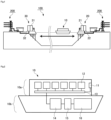
- FIG. 2 illustrates the main elements of the transportation ship 10.
- the transportation ship 10 is of a motor type that uses electricity as a power source.
- the transportation ship 10 may be of an internal combustion engine type using fossil fuel as a power source, or may be of a hybrid type that uses both a motor and an internal combustion engine.
- the transportation ship 10 may be powered by hydrogen as a power source.
- the transportation ship 10 may be of a fuel cell type that drives a motor using electricity generated by a fuel cell, or the transportation ship 10 may be of a hydrogen engine type that obtains power by burning hydrogen by an internal combustion engine.
- the transportation ship 10 includes a container 10a and a hull 10b.
- the container 10a is configured to be removable from the hull 10b.
- the hull 10b is configured to be able to navigate independently even when the container 10a is removed.
- the container 10a is an element for holding an energy source (specifically, electricity) to be transported from the supply facility 20 to the reception facility 30.
- the electricity stored in the container 10a is intended for transportation from the supply facility 20 to the reception facility 30, and thus during transportation, the electricity is basically held as is without being consumed as a power source for the transportation ship 10 and the equipment inside the ship.
- the electricity stored in the container 10a may also be used as a power source for the transportation ship 10, or the like.
- the container 10a includes a charging/discharging port 11, a plurality of battery cells 12, and a battery control device 13.
- the battery cells 12 are storage batteries installed within the container 10a. Depending on the number of battery cells 12 installed, the electrical capacity that can be stored in the container 10a of the transportation ship 10 can be adjusted. For example, depending on the size of the transportation ship 10, the container 10a is capable of securing an electrical capacity of 200 to 6000 MWh.
- the battery control device 13 is connected to each battery cell 12 and is a control circuit for controlling the amount of charge/discharge of electricity to each battery cell 12 and the rate of charge/discharge.
- the battery control device 13 includes, on a circuit board, a CPU, a memory for storing a control program, a communication device with an external server device, a sensor device for detecting, for example, a state of charge of the battery cells 12, and the like.
- the container 10a is configured to be removable from the hull 10b, but it may also be configured such that each battery cell 12 is removable from the container 10a.
- the container 10a itself may be fixed to the hull 10b in a non-removable manner.
- the battery control device 13 is installed inside the container 10a; however, instead of this configuration, the battery control device 13 may also be installed on the hull 10b side.
- the hull 10b of the transportation ship 10 basically has the same configuration as a general motor-type ship using electricity as a power source. That is, the hull 10b includes a drive battery 14, an inverter 15, and a motor 16.
- the drive battery 14 holds electricity that is consumed as a power source for the transportation ship 10 and internal equipment.
- the inverter 15 controls or converts the electricity output from the drive battery 14 and supplies the electricity to the motor 16.
- the motor 16 converts the electricity received from the inverter 15 into power. For example, the motor 16 obtains a propulsion force for the transportation ship 10 by rotating a screw propeller via a shaft (not illustrated).
- the hull 10b has the drive battery 14 that is separate from the battery cells 12 for storing electricity for transportation, and therefore navigating is possible without consuming the electricity in the battery cells 12.
- the drive battery 14 is electrically connected to the battery cells 12 via the battery control device 13. Therefore, in an emergency or the like, electricity in the battery cells 12 may be supplied to the drive battery 14.
- the transportation ship 10 is also able to navigate using the electricity in the battery cells 12 as a power source.
- the transportation ship 10 may transport hydrogen instead of electricity as an energy source.
- a hydrogen tank may be installed in the container 10a instead of the battery cells 12.
- the transportation ship 10 may be one that navigates using hydrogen as a power source.
- a fuel cell may be installed in the hull 10b instead of the drive battery 14. Note that hydrogen can be transported by the transportation ship 10 that uses electricity as a power source, and electricity can also be transported by the transportation ship 10 that uses hydrogen as a power source.
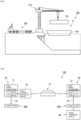
- FIG. 3 schematically illustrates a method of supplying electricity from the coastal supply facility 20 to the battery cells 12 of the transportation ship 10.
- the supply of electric power from the supply facility 20 to the transportation ship 10 is basically performed via the charging/discharging cable 40 while the transportation ship 10 remains at sea.
- the transportation ship 10 may be parked near the supply facility 20 by lowering the anchor, or may be parked near the supply facility 20 by controlling the motor and screw propeller without lowering the anchor.
- the charging/discharging cable 40 may be provided on the transportation ship 10 or may be provided at the supply facility 20.
- the supply of electric power from the supply facility 20 to the transportation ship 10 is basically performed for the purpose of supplying electric power (stored in the battery cells 12) as an energy source to be transported to the reception facility 30.
- electric power electric power to be stored in the drive battery 14
- this is not the main purpose.
- the transportation ship 10 includes a robot arm 50 for suspending and gripping the charging/discharging cable 40. By gripping the charging/discharging cable 40 with the robot arm 50, the transportation ship 10 can be charged without the charging/discharging cable 40 touching the sea surface.
- the robot arm 50 preferably includes a stabilizer mechanism for maintaining the spatial position (horizontal position and vertical position) of the gripped site of the charging/discharging cable 40 constant.
- the stabilizer mechanism may mechanically maintain the spatial position of the gripped site.
- the stabilizer mechanism may electronically perform control so as to maintain the spatial position of the gripped site based on detection information from a sensor device such as an acceleration sensor, a gyro sensor, or the like.
- the supply of electric power to the transportation ship 10 is performed at sea, and is easily affected by waves and tides.
- FIG. 4 schematically illustrates methods of supplying electricity from the transportation ship 10 to the coastal reception facility 30.
- the supply of electric power from the transportation ship 10 to the reception facility 30 be performed via the charging/discharging cable 40 while the transportation ship 10 remains offshore.
- the transportation ship 10 may be anchored at the port.
- the onshore reception facility 30 includes a power transformer 31.
- the electricity stored in the battery cells 12 of the transportation ship 10 is supplied to the power transformer 31 via the charging/discharging cable 40 gripped by the robot arm 50. Since DC electricity is stored in the battery cells 12, the power transformer 31 converts the DC electricity to AC electricity, and then transmits the AC electricity to the power system 200 via the power transmission cable 32. Note that although not illustrated, it is also possible to supply electricity from the transportation ship 10 to the power transformer 31 with the charging/discharging cable 40 floating on the sea surface and without the robot arm 50 being mounted on the transportation ship 10.
- power is supplied from the transportation ship 10 to another ship 34 on the sea.
- An example of the ship 34 is a motor-type ship that navigates using electricity as a power source.
- the ship 34 is able to charge the drive battery while offshore.
- the supply destination of the energy source from the transportation ship 10 is not limited to the onshore reception facility 30, but can also be a ship 34 on the ocean that requires an energy source such as electricity.
- the supply destination (reception facility) of the energy source from the transportation ship 10 may be a vehicle (EV or FCV) that is onshore, and it is also possible to directly supply an energy source to various locations such as commercial facilities, hospitals, residences, and public transportation facilities. In this manner, with the present invention, it becomes possible to freely select a destination for transporting the energy source by the transportation ship 10.
- EV or FCV vehicle
- FCV public transportation facilities
- FIG. 5 illustrates a method for removing the container 10a from the transportation ship 10 and delivering the container 10a individually.
- the transportation ship 10 is configured such that the container 10a containing the battery cells 12 can be removed from the hull 10b.
- the container 10a can be removed from the hull 10b by a crane 310, and the container 10a can be loaded onto a trailer 320.
- large-capacity containers 10a can be individually delivered to various regions and locations. For example, it is possible to freely deliver an energy source (electricity) to rural areas, to mountains and forests, to construction sites, and the like where power transmission lines are not installed.
- the method for delivering the container 10a is not limited to the trailer 320, and other land transportation methods such as trains, air transportation methods such as helicopters and airplanes, and sea transportation methods such as cargo ships may also be used. It is also possible to unload and store the container 10a as is at a port as a backup power source.
- FIG. 6 illustrates a power transmission scheme assumed in the present invention.
- AC electricity generated by the power generation facility 60 is transmitted to the supply facility 20 via the power system 200.
- the power transformer 21 converts the AC electricity into DC electricity.
- the power transformer 21 converts the electricity into high-voltage DC electricity (HVDC) of about 200 kV to 500 kV.
- HVDC high-voltage DC electricity
- This high-voltage DC electricity is then supplied from the power transformer 21 to the transportation ship 10. In this way, by charging the battery cells of the transportation ship 10 with high-voltage DC electricity, power loss during transportation can be suppressed.
- electric power is supplied from the transportation ship 10 to the reception facility 30 similarly using high-voltage DC electricity. Therefore, it is necessary to provide the current collector board 33 and the power transformer 31 for high-voltage DC electricity on the reception facility 30 side as well.
- the electricity held by the battery cells of the transportation ship 10 is supplied to the power transformer 31 via the current collector board 33.
- the power transformer 31 converts the high-voltage DC electricity into AC electricity of about 100V to 250V that meets the standards of each region, and then transmits the electricity to the power system 200 via the power transmission cable 32.
- the energy transportation system 100 includes the power generation facility 60.
- the power generation facility 60 includes a power generator 61 and a power transformer 62.
- the power generator 61 it is possible to employ a power generation method that uses renewable energy such as, not only a wind power generator 61a, but also a solar power generator 61b, a tidal power generator 61c, a geothermal power generator 61d, a hydroelectric power generator 61e, and a biomass power generator 61f.
- a thermal power generator or a nuclear power generator can also be used as the power generator 61.
- one type selected from among these types of power generators 61a to 61f or the like may be used for power generation, or a plurality of types of power generators may be combined and used for power generation. Note that, since each type of power generator is already well-known, the detailed structure of each type of power generator will not be explained. Electric power generated by the power generator 61 is supplied to the public power system 200 via the power transformer 62.
- electricity is used as an energy source for transportation. That is, the supply facility 20 supplies electricity acquired from the power system 200 to the transportation ship 10.
- the transportation ship 10 charges the battery cells 12 with electricity in this manner and transports the power via sea route. For this reason, as in the transportation system illustrated in the upper part of FIG. 7 , at the supply facility 20, the electricity is converted from AC electricity to DC electricity by the power transformer 21, and the battery cells 12 of the transportation ship 10 are charged, and then at the reception facility 30 as well, the electricity supplied from the battery cells 12 is converted from DC electricity to AC electricity by the power transformer 31 and transmitted to the power system 200.
- hydrogen may also be used as an energy source for transportation.
- the supply facility 20 supplies electricity acquired from the power system 200 to water electrolysis equipment 23.
- the water electrolysis equipment 23 electrolyzes water, using electricity to generate high purity hydrogen gas.
- Hydrogen gas generated by the water electrolysis equipment 23 is supplied to the transportation ship 10 anchored or parked offshore via a hydrogen gas supply nozzle (supply line).
- the transportation ship 10 is provided with a hydrogen tank 17, and the hydrogen gas supplied from the water electrolysis equipment 23 is stored in the hydrogen tank 17.
- the hydrogen gas supply line is preferably held by the robot arm 50 of the transportation ship 10, as in the example illustrated in FIG. 3 .
- the transportation ship 10 navigates toward the reception facility 30.
- a fuel cell 35 is provided at the reception facility 30.
- Hydrogen gas is supplied to the fuel cell 35 from the hydrogen tank 17 of the transportation ship 10 via a supply nozzle (supply line).
- the fuel cell 35 generates electricity by causing a chemical reaction between hydrogen supplied from the transportation ship 10 and oxygen in the air.
- the electricity obtained by the fuel cell 35 is transformed as necessary and then transmitted to the power system 200. In this way, by transporting hydrogen by the transportation ship 10, the energy source obtained at the supply facility 20 can be delivered to the reception facility 30.
- the energy transportation system 100 may include either the electricity transportation system (upper example) or the hydrogen transport system (lower example) illustrated in FIG. 7 , or may include both of these transportation systems. That is, it is possible to select and execute electricity transportation and hydrogen transportation as necessary.
- the present invention relates to an energy transportation system and an energy transportation method.
- the present invention may be suitably used in the power generation business and the power transmission business.
Landscapes
- Engineering & Computer Science (AREA)
- Power Engineering (AREA)
- Chemical & Material Sciences (AREA)
- Combustion & Propulsion (AREA)
- Mechanical Engineering (AREA)
- Ocean & Marine Engineering (AREA)
- Architecture (AREA)
- Civil Engineering (AREA)
- Structural Engineering (AREA)
- Charge And Discharge Circuits For Batteries Or The Like (AREA)
- Management, Administration, Business Operations System, And Electronic Commerce (AREA)
Applications Claiming Priority (2)
| Application Number | Priority Date | Filing Date | Title |
|---|---|---|---|
| JP2021132402 | 2021-08-16 | ||
| PCT/JP2022/030729 WO2023022103A1 (fr) | 2021-08-16 | 2022-08-12 | Système et procédé de transport d'énergie par navire |
Publications (2)
| Publication Number | Publication Date |
|---|---|
| EP4391298A1 true EP4391298A1 (fr) | 2024-06-26 |
| EP4391298A4 EP4391298A4 (fr) | 2025-08-27 |
Family
ID=85240719
Family Applications (1)
| Application Number | Title | Priority Date | Filing Date |
|---|---|---|---|
| EP22858424.9A Pending EP4391298A4 (fr) | 2021-08-16 | 2022-08-12 | Système et procédé de transport d'énergie par navire |
Country Status (10)
| Country | Link |
|---|---|
| US (1) | US20240326958A1 (fr) |
| EP (1) | EP4391298A4 (fr) |
| JP (1) | JPWO2023022103A1 (fr) |
| KR (1) | KR20240047339A (fr) |
| CN (1) | CN117426041A (fr) |
| AU (1) | AU2022330651A1 (fr) |
| CA (1) | CA3225424A1 (fr) |
| IL (1) | IL309398A (fr) |
| TW (1) | TW202310529A (fr) |
| WO (1) | WO2023022103A1 (fr) |
Family Cites Families (26)
| Publication number | Priority date | Publication date | Assignee | Title |
|---|---|---|---|---|
| JPS62281738A (ja) * | 1986-05-27 | 1987-12-07 | 川崎重工業株式会社 | 洋上電力貯蔵装置 |
| DE10224808A1 (de) * | 2002-06-05 | 2003-12-18 | Aloys Wobben | Verfahren zum Transportieren elektrischer Energie |
| JP2005220946A (ja) * | 2004-02-03 | 2005-08-18 | Mitsubishi Heavy Ind Ltd | 水素の輸送システム |
| JP5711133B2 (ja) * | 2008-10-07 | 2015-04-30 | プレミアム パワー コーポレイション | エネルギーを移送するためのシステムおよび方法 |
| US20100116684A1 (en) * | 2008-10-10 | 2010-05-13 | Mr. Carleton E. Sawyer | Wind to hydrogen energy conversion |
| JP5546122B2 (ja) * | 2008-12-08 | 2014-07-09 | ジャパンマリンユナイテッド株式会社 | 蓄電池パッケージ |
| DE102009051215A1 (de) * | 2009-10-29 | 2011-05-12 | Li-Tec Battery Gmbh | Windkraftanlage mit Batterieanordnung |
| US20120038210A1 (en) * | 2010-08-11 | 2012-02-16 | Seahorse Equipment Corp. | Apparatus and method for electric floating storage and offloading |
| KR101259817B1 (ko) * | 2011-09-22 | 2013-04-30 | 삼성중공업 주식회사 | 해상 풍력 단지의 송전 시스템 및 그 방법 |
| JP2013183521A (ja) * | 2012-03-01 | 2013-09-12 | Hitachi Ltd | 移動型蓄電媒体を用いた分散電源制御装置、方法、およびプログラム |
| KR101304913B1 (ko) * | 2012-03-23 | 2013-09-05 | 삼성중공업 주식회사 | 해상 풍력 단지의 송전 시스템 및 그 방법 |
| CN202616885U (zh) * | 2012-06-07 | 2012-12-19 | 高平唐一新能源科技有限公司 | 一种大容量锂电池储能电站 |
| JP6131569B2 (ja) * | 2012-11-06 | 2017-05-24 | 住友電気工業株式会社 | 洋上風力発電用配線システム及び洋上風力発電システム |
| JP5853969B2 (ja) | 2013-02-15 | 2016-02-09 | 三菱電機株式会社 | 電力輸送網システム |
| JP6445908B2 (ja) * | 2014-09-29 | 2018-12-26 | 積水化学工業株式会社 | 電力配送システム及び電力配送方法 |
| JP5921647B1 (ja) * | 2014-11-20 | 2016-05-24 | 有限会社板厚計測Bスコープ | 潮流又は海流を使用して発電する海域での発電設備 |
| DK201670190A1 (en) * | 2016-03-31 | 2017-10-09 | A P Møller - Mærsk As | Boat with connection to shore |
| CN106505689A (zh) * | 2016-12-23 | 2017-03-15 | 南通东源新能源科技发展有限公司 | 一种储能电站 |
| CN109412228A (zh) * | 2018-10-29 | 2019-03-01 | 中国船舶重工集团公司第七〇九研究所 | 深远海岛礁核储供电系统 |
| CN211376706U (zh) * | 2019-12-11 | 2020-08-28 | 银隆新能源股份有限公司 | 储能系统 |
| CN211744062U (zh) * | 2019-12-12 | 2020-10-23 | 比亚迪股份有限公司 | 储能电池集装箱 |
| JP6705071B1 (ja) * | 2020-03-04 | 2020-06-03 | 正通 亀井 | 広域電力供給システム |
| CN112161196A (zh) * | 2020-09-14 | 2021-01-01 | 浙江大学 | 一种基于现有海上风电场的海水制氢输送系统及方法 |
| CN111969153A (zh) * | 2020-09-21 | 2020-11-20 | 刘伟华 | 集装箱式储能系统 |
| TW202245375A (zh) * | 2021-05-10 | 2022-11-16 | 日商帕瓦艾克司股份有限公司 | 藉由船舶的能源輸送系統及能源輸送方法 |
| CN113764777B (zh) * | 2021-09-16 | 2023-01-31 | 远景能源有限公司 | 一种储能电池集装箱 |
-
2022
- 2022-08-12 EP EP22858424.9A patent/EP4391298A4/fr active Pending
- 2022-08-12 WO PCT/JP2022/030729 patent/WO2023022103A1/fr not_active Ceased
- 2022-08-12 AU AU2022330651A patent/AU2022330651A1/en active Pending
- 2022-08-12 JP JP2023542383A patent/JPWO2023022103A1/ja active Pending
- 2022-08-12 US US18/575,369 patent/US20240326958A1/en active Pending
- 2022-08-12 KR KR1020237044194A patent/KR20240047339A/ko active Pending
- 2022-08-12 CN CN202280039920.7A patent/CN117426041A/zh active Pending
- 2022-08-12 IL IL309398A patent/IL309398A/en unknown
- 2022-08-12 CA CA3225424A patent/CA3225424A1/fr active Pending
- 2022-08-15 TW TW111130599A patent/TW202310529A/zh unknown
Also Published As
| Publication number | Publication date |
|---|---|
| EP4391298A4 (fr) | 2025-08-27 |
| CN117426041A (zh) | 2024-01-19 |
| WO2023022103A1 (fr) | 2023-02-23 |
| KR20240047339A (ko) | 2024-04-12 |
| AU2022330651A1 (en) | 2024-01-04 |
| US20240326958A1 (en) | 2024-10-03 |
| TW202310529A (zh) | 2023-03-01 |
| JPWO2023022103A1 (fr) | 2023-02-23 |
| CA3225424A1 (fr) | 2023-02-23 |
| IL309398A (en) | 2024-02-01 |
Similar Documents
| Publication | Publication Date | Title |
|---|---|---|
| EP4340173A1 (fr) | Système et procédé de transport d'énergie par navire | |
| US20230012122A1 (en) | System and method for reduction of power consumption and emissions of marine vessels | |
| US20120038210A1 (en) | Apparatus and method for electric floating storage and offloading | |
| KR101259817B1 (ko) | 해상 풍력 단지의 송전 시스템 및 그 방법 | |
| CZ100099A3 (cs) | Energetický systém s palivovým článkem | |
| CN101478268B (zh) | 利用自然能向电动船舶供能的系统和方法 | |
| CN101412376B (zh) | 利用自然能向电动汽车供能的系统和方法 | |
| KR101644873B1 (ko) | 전력 운송 시스템 및 이를 이용한 전력 운송 방법 | |
| JP7814764B2 (ja) | 燃料電池システムを備えた電気車両用充電ステーション | |
| WO2022149000A1 (fr) | Station de charge en mer | |
| EP4391298A1 (fr) | Système et procédé de transport d'énergie par navire | |
| RU2852632C2 (ru) | Система и способ транспортировки электроэнергии морским судном | |
| JP2020099171A (ja) | 急速充電ステーション | |
| JP2020099128A (ja) | 急速充電ステーション | |
| KR101736375B1 (ko) | 이차전지를 이용하여 전력을 운송하는 전력 운송선 및 이를 활용한 전력 운송 시스템 및 방법 | |
| US20260034905A1 (en) | Moving body and power transmission method | |
| US20260039118A1 (en) | Power generation facility and power output method | |
| JP2026067586A (ja) | 電力輸送方法 | |
| KR101475916B1 (ko) | 전력 운송 시스템 및 이를 이용한 전력 운송 방법 | |
| EA050634B1 (ru) | Зарядный комплекс для электрических транспортных систем | |
| WO2023219515A1 (fr) | Système d'alimentation en énergie en mer |
Legal Events
| Date | Code | Title | Description |
|---|---|---|---|
| STAA | Information on the status of an ep patent application or granted ep patent |
Free format text: STATUS: THE INTERNATIONAL PUBLICATION HAS BEEN MADE |
|
| PUAI | Public reference made under article 153(3) epc to a published international application that has entered the european phase |
Free format text: ORIGINAL CODE: 0009012 |
|
| STAA | Information on the status of an ep patent application or granted ep patent |
Free format text: STATUS: REQUEST FOR EXAMINATION WAS MADE |
|
| 17P | Request for examination filed |
Effective date: 20240304 |
|
| AK | Designated contracting states |
Kind code of ref document: A1 Designated state(s): AL AT BE BG CH CY CZ DE DK EE ES FI FR GB GR HR HU IE IS IT LI LT LU LV MC MK MT NL NO PL PT RO RS SE SI SK SM TR |
|
| DAV | Request for validation of the european patent (deleted) | ||
| DAX | Request for extension of the european patent (deleted) | ||
| A4 | Supplementary search report drawn up and despatched |
Effective date: 20250725 |
|
| RIC1 | Information provided on ipc code assigned before grant |
Ipc: H02J 15/00 20060101AFI20250721BHEP Ipc: B63B 25/02 20060101ALI20250721BHEP Ipc: B63B 25/14 20060101ALN20250721BHEP Ipc: B63B 25/16 20060101ALN20250721BHEP Ipc: B63B 35/44 20060101ALN20250721BHEP Ipc: B63H 21/17 20060101ALN20250721BHEP Ipc: B63H 21/00 20060101ALN20250721BHEP Ipc: B63J 3/00 20060101ALN20250721BHEP |