EP0580049A1 - Piezo-elektrischer Motor - Google Patents
Piezo-elektrischer Motor Download PDFInfo
- Publication number
- EP0580049A1 EP0580049A1 EP93111102A EP93111102A EP0580049A1 EP 0580049 A1 EP0580049 A1 EP 0580049A1 EP 93111102 A EP93111102 A EP 93111102A EP 93111102 A EP93111102 A EP 93111102A EP 0580049 A1 EP0580049 A1 EP 0580049A1
- Authority
- EP
- European Patent Office
- Prior art keywords
- rotor
- stator
- support
- piezoelectric
- piezoelectric motor
- Prior art date
- Legal status (The legal status is an assumption and is not a legal conclusion. Google has not performed a legal analysis and makes no representation as to the accuracy of the status listed.)
- Granted
Links
Images


Classifications
-
- H—ELECTRICITY
- H02—GENERATION; CONVERSION OR DISTRIBUTION OF ELECTRIC POWER
- H02N—ELECTRIC MACHINES NOT OTHERWISE PROVIDED FOR
- H02N2/00—Electric machines in general using piezoelectric effect, electrostriction or magnetostriction
-
- H—ELECTRICITY
- H02—GENERATION; CONVERSION OR DISTRIBUTION OF ELECTRIC POWER
- H02N—ELECTRIC MACHINES NOT OTHERWISE PROVIDED FOR
- H02N2/00—Electric machines in general using piezoelectric effect, electrostriction or magnetostriction
- H02N2/10—Electric machines in general using piezoelectric effect, electrostriction or magnetostriction producing rotary motion, e.g. rotary motors
- H02N2/103—Electric machines in general using piezoelectric effect, electrostriction or magnetostriction producing rotary motion, e.g. rotary motors by pressing one or more vibrators against the rotor
-
- G—PHYSICS
- G04—HOROLOGY
- G04C—ELECTROMECHANICAL CLOCKS OR WATCHES
- G04C3/00—Electromechanical clocks or watches independent of other time-pieces and in which the movement is maintained by electric means
- G04C3/08—Electromechanical clocks or watches independent of other time-pieces and in which the movement is maintained by electric means wherein movement is regulated by a mechanical oscillator other than a pendulum or balance, e.g. by a tuning fork, e.g. electrostatically
- G04C3/12—Electromechanical clocks or watches independent of other time-pieces and in which the movement is maintained by electric means wherein movement is regulated by a mechanical oscillator other than a pendulum or balance, e.g. by a tuning fork, e.g. electrostatically driven by piezoelectric means; driven by magneto-strictive means
-
- H—ELECTRICITY
- H02—GENERATION; CONVERSION OR DISTRIBUTION OF ELECTRIC POWER
- H02N—ELECTRIC MACHINES NOT OTHERWISE PROVIDED FOR
- H02N2/00—Electric machines in general using piezoelectric effect, electrostriction or magnetostriction
- H02N2/0005—Electric machines in general using piezoelectric effect, electrostriction or magnetostriction producing non-specific motion; Details common to machines covered by H02N2/02 - H02N2/16
- H02N2/001—Driving devices, e.g. vibrators
- H02N2/0015—Driving devices, e.g. vibrators using only bending modes
-
- H—ELECTRICITY
- H02—GENERATION; CONVERSION OR DISTRIBUTION OF ELECTRIC POWER
- H02N—ELECTRIC MACHINES NOT OTHERWISE PROVIDED FOR
- H02N2/00—Electric machines in general using piezoelectric effect, electrostriction or magnetostriction
- H02N2/0005—Electric machines in general using piezoelectric effect, electrostriction or magnetostriction producing non-specific motion; Details common to machines covered by H02N2/02 - H02N2/16
- H02N2/005—Mechanical details, e.g. housings
- H02N2/0065—Friction interface
Definitions
- the present invention relates to a piezoelectric motor.
- the invention relates to a thin piezoelectric motor which can be fitted to a timepiece.
- FIG. 1 A small piezoelectric motor capable of satisfying such an application is described in patent application CH 02 553 / 91-0, filed on August 30, 1991 in the name of the applicant.
- This piezoelectric motor which is shown in Figures 1, 2 and 3 appended and which will be described in detail below, conventionally comprises, on the one hand, a stator associated with piezoelectric means, and on the other hand apart, a rotor which is rotatably mounted on this stator.
- the piezoelectric means consist of a polarized ceramic which can be electrically excited to involve a vibratory movement on the stator, while the rotor is provided with bending blades arranged in elastic support on the stator. These blades are shaped to ensure the transmission of this vibratory movement to the rotor.
- support means comprising a spring in the form of a cup.
- This spring is held axially by a head screw engaged in a stepped fixed axis which forms a support and which urges the rotor along this axis. Between the head of the screw and the spring is disposed a bearing allowing the concomitant rotation of the rotor-spring assembly.
- This motor has a space requirement in height such that it cannot be fitted to timepieces having by nature a small thickness.
- the present invention aims to overcome this drawback by providing a piezoelectric motor thin enough to equip a timepiece without affecting its dimensional characteristics.
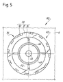
- This motor which is identified by the general reference M1, comprises a support 2 which is, in this example, constituted by a base 4 in which is embedded, in particular by force fitting of the hunting type, a stepped pin or tenon 6 protruding .
- the pin 6 materializes a geometric axis X1, forming a geometric axis of rotation around which a rotor R1 can rotate.
- the base 4 and the post 6 are made of a metallic material, such as brass or an alloy of the stainless steel type.
- the base assembly 4 - stud 6 therefore constitutes a fixed structure forming the support of this piezoelectric motor.
- the motor M1 also includes a stator S1 which is fixedly mounted, likewise by force fitting (driving) or by bonding, on the post 6.
- piezoelectric means 10 consisting, on the one hand, of a piezoelectric element 10a, such as a ceramic which is polarized uniformly according to its thickness, and on the other hand, of two electrodes 10b and 10c which are conventionally connected to a power supply AL, shown here schematically.
- the piezoelectric means 10 therefore form a transducer which, in response to an electrical excitation supplied by the supply AL via the electrodes 10b and 10c can take on a vibratory movement.
- the stator S1 is constituted by a disc 12 having in its center a through hole 14 which, in this example, is fixedly held on the post 6.
- the disc 12 which forms the framework of the stator S1 rests in axial support on a shoulder 16 of this post.
- a face F1 of the disc 12 disposed facing the base 4 and called the rear face, is hollowed out in its central part to reveal a blind recess or recess 18, opening towards the base 4.
- This recess 18 defines on the rear face F1 of the disc 12, an annular collar 20 on which are fixedly mounted the piezoelectric means 10 which have the same annular shape.
- the rotor R1 As for the rotor R1, it rests axially on a face F2 of the disc 12, opposite the face F1, while it is freely engaged by a central orifice 32 on the post 6.
- the rotor R1 comprises a body which is formed, in this embodiment, by a disc D1 of thin thickness made of a material such as metal, ceramic or hard plastic.
- the disc D1 forms a rigid and load-bearing structure which can mesh with coupling means, not shown.
- the piezoelectric motor M1 further comprises motion transmission means 36 shaped to transmit to the rotor R1 the vibratory movement of the stator S1 and to move the rotor R1 in rotation around its axis X1, in a normal plane of movement Pdm to the axis of rotation X1.
- These transmission means 36 are formed by elastically deformable members constituted by blades of flexion 38.
- the flexion blades 38 are, in the example of FIG. 1, embedded in the disc D1 forming the support structure or body of the rotor R1.
- the rotor R1 is biased in the axial direction towards the stator S1 by means of support means 39.
- These means 39 which allow the axial support of the rotor R1 on the stator S1 here consist of a cup-shaped spring 42 mounted on the post 6 and biased in the axial direction by a bearing 44 which is itself disposed on the post 6 and which is held thereon by a head screw V1 mounted at the free end of said post.
- These support means allow the adjustment of the support pressure of the rotor R1 on the stator S1, by screwing or unscrewing the screw V1.
- FIGS 2 and 3 show a particular embodiment of the rotor described in the aforementioned Swiss application.
- the elastically deformable members 36 are constituted by curved bending blades 50 (of which only one is referenced) formed on a solid disc 52 with which the latter come in one piece.
- the disc 52 is attached under the disc D1 forming the body of the rotor R1 and it is fixedly integral with the latter.
- the flexure blades 50 are formed at the periphery of the disc 52 by a cold deformation operation, and in particular by stamping.
- the motor M2 comprises a rotor R2 which is rotatably mounted, around the geometric axis X1, on a stator S2 embedded in the base 4.
- the stator S2 comprises a support structure ensuring the support of the rotor R2, this structure essentially consisting of a suspended annular plate P2 fixedly held in the base 4.
- the plate P2 is formed, on the one hand, by a disc 60 elastically deformable under which the piezoelectric means 10 are subjected and which has a low uniform thickness, of the order of 0.1 mm (0.1.10 ⁇ 3 meter)
- the plate P2 further comprises a cylindrical tubular barrel 62 projecting from the disc 60 and coming integrally with it.
- the barrel 62 is therefore fixedly removed by force fitting or by bonding in an orifice, not referenced, of the base 4.
- the barrel 62 has a central orifice opening 64 into which is driven a smooth cylindrical tenon with a head V2 which ensures the axial maintenance and the guiding in rotation of the rotor R2 around the axis X1, thanks to two coaxial bearing surfaces (not referenced) formed on this one.
- the rotor R2 comprises a stepped tubular hub 66 of rigid structure, mounted for rotation about the axis X1, on the stud V2.
- the hub 66 comprises mechanical drive means formed, for example, by an external toothing 67 formed at the periphery thereof.
- the toothing 67 is intended to mesh with a drive mechanism, not shown.
- the hub 66 furthermore comprises, under its toothing 67 (taking the motor M2 in its position shown in FIG. 4) a shouldered seat 68 on which the body of the rotor R2 is fixedly engaged.
- the rotor body R2 is, according to the invention, essentially constituted by a perforated flexible disc D2.
- the disc D2 has an annular central part 70 (FIG. 6) which has a central opening 72 and which is connected, by this opening, to the hub 66 while being fixedly engaged on the carried shoulder 68.
- the disc D2 also includes a peripheral ring 72 on which the flexure blades 50 are formed.
- the disc D2 comprises bending arms 74 (for example here four in number, only one being referenced) which resiliently connect the central part 70 and the peripheral ring 72.
- the transmission means 36 which are formed by the bending blades 50 extending from the peripheral ring 72 towards the stator S2, the bending arms 74, the central part 70, as well as the ring 72 are made of material and form a monolithic rotor part.
- the peripheral ring 72, the bending arms 74 and the central part 70 have the same thickness and are, in the rest state (FIGS. 7 and 9), arranged in the same plane (not referenced).
- the body of the rotor R2 is formed by a structure which is elastically deformable, at least in the direction of the stator S2, and which at least partly forms the elastic support means of the rotor R2 on the stator S2, these means being referenced 79.
- These means are also formed in part by the hub 66 which biases the disk D2 axially towards the stator in an axisymmetric manner (relative to the axis X1), while being held by the head, not referenced, of the embedded stud V2.
- the body of the rotor R2 is formed essentially by the elastically disc deformable D2 which forms in an integrated manner said transmission means 36 and said elastic support means 79.
- the hub 66 permanently deforms, under the action of the pin V2, the body of the rotor R2 which is prestressed and which takes the form of bowl.
- the electrodes 10b and 10c of the piezoelectric means 10 both in front projection a full and entire structure, that is to say not cut and not structured by polarized segments, as is the case in classical structures.
- the disc D2 forming the stator S2 is preferably made of a metallic material, such as brass, a stainless steel alloy or aluminum, possibly coated with a thin layer of a hard material, especially chromium or titanium nitride.
- the electrodes 10b and 10c are preferably made of nickel or silver.
- the flexure blades 50 therefore project from the rotor R2, and in particular from the disk D2, in the direction of the front face of the stator S2 at an angle of inclination ⁇ originating from a straight line parallel to the axis of rotation X1.
- the angle ⁇ is between 10 and 30 °.
- each bending blade 50 which has a planar shape of the parallelepiped type protrudes from the rotor R2 over a free length Lcs preferably chosen in values between 0.1 and 0.5 mm (0.1 and 0, 5.10 ⁇ 3 meters).
- each blade 50 has a thickness ec having a value between 0.025 and 0.1 mm (0.025 and 0.1.10 ⁇ 3 meters) and a width lc having a value lying between 0.1 and 0.3 mm (0 , 1 and 0.3.10 ⁇ 3 meters).
- the flexure blades 50 are made of a material, such as an alloy of the beryllium-copper type or of the stainless steel type.
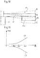
- stator S2 has a bending deformation on either side of its rest position identified by the reference A1. This deformation is very exaggerated by the extreme high and low positions B and C, and in reality it does not exceed a beat amplitude greater than 5 ⁇ m (5.10 ⁇ 6 meters), at the periphery of the stator (arrow). This deformation gives the stator S2 a bowl shape. This deformation in the bowl is due to bending stresses generated in the stator S2 thanks to the piezoelectric means 10. These bending stresses are due to the heterogeneous bimorph structure formed by the rigid assembly of the piezoelectric means 10 on the stator S2.
- a particular ceramic which is adapted to deform radially when a specific electrical excitation, via the electrodes, is applied to it. More particularly, a ceramic is chosen having a piezoelectric constant d, high, this constant representing the deformation obtained with respect to the applied field.
- this vibratory movement and this axisymmetric deformation are centered on the axis of rotation X1.
- a stepped planar motor that is to say having a stator and a rotor of essentially planar shape and superimposed, motor which thanks to the axisymmetric movement centered on the axis of rotation and oriented according to it, is of the essentially axial vibratory movement type, with reference to the axis X1.
- each point for example Pt1 to Pt3 (figure 9) of the stator S2 performs at least in projection on the axis X1, an essentially linear displacement, in a parallel direction to the axis of rotation X1, of the same amplitude for each circle registered rotor at a given radius (for example Rb1 to Rbn) and in phase.
- the axisymmetric vibration mode of the piezoelectric motor according to the invention provides speed components T (only three, T1 to T3, being represented in FIG. 9) essentially normal to the plane of movement Pdm of the rotor R2.
- the stator S2 therefore has no significant speed component in the displacement plane Pdm in view of the extremely low vibration amplitudes. It therefore has no significant radial, centrifugal or centripetal acceleration. It is also remarkable to note that this stator does not present any tangential acceleration, acceleration which one finds on the opposite in the stators of the classic piezoelectric motors having a vibratory mode with progressive waves or stationary.
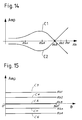
- FIG. 13 represents the deformation of the stator S2 when it is subjected to a second variant of the axisymmetric vibratory movement according to the invention, the reference D representing its rest position, while the references E and F represent the shape of the stator in its extreme positions of deformation when excited.
- This movement this time has a nodal circle, identified in particular at the radius Rb3 ( Figures 14 and 15). It is in fact noted that the curves C1 and C2 in FIG. 14 pass through an amplitude of zero value marking a vibration node in the stator.
- the disc 60 is in this case made of a stainless steel alloy, while the piezoelectric element 10a is made of a piezoelectric ceramic PZT type (Zirconium doped lead titanium).
- the vibration mode of the motor according to the invention can be generalized to a notation of the type B xo ; where x can vary from 0 to a number n.
- the piezoelectric means 10 are excited by the electrical supply AL, which makes them vibrate.
- the radial component of the vibration of the piezoelectric means 10 generates a bending vibration of the disc 60 by the principle of the heterogeneous bimorph, known to those skilled in the art.
- the power supply AL delivers an alternating signal of frequency F corresponding to the resonance frequency of the mode B X0 desired.
- stator S2 in its entirety is thus excited in resonance in mode B X0 corresponding to an axisymmetric vibratory movement as described above.
- the elastically deformable members 36 formed by the bending blades 50 therefore form movement transformation means capable of transmitting, and at the same time transforming, the essentially axial linear (or normal) movement of the stator, into a perpendicular rotary movement of the rotor. .
- the motor M3 comprises a stator S3 which is provided with the piezoelectric element 10 and the annular disc 60, described above. On this stator S3 is mounted a rotor R3 whose body which is identical to the rotor R2, comprises a perforated flexible disc D3 of the same structure as the disc D2.
- the rotor R3 differs in that it comprises a stepped hub 80 driven on a drive axis 82 passing through the stator S3, through a barrel 84 made in one piece with the disc 60 of the suspended plate P3.
- the hub 80 only supports the perforated flexible disk D3 to keep it stressed, as shown in FIG. 8, under elastic stress, towards the plate P3 of the rotor R3.
- the drive shaft 82 is mounted by a first guide means 86 formed by a pivot (same reference) rotatably mounted in a bearing 88 formed, in this example, by a driven stone in a second support 89 formed by a plate or by a bridge of a clockwork movement, shown here partially.
- This axis 82 is supported in rotation by a second guide means 90 constituted by a cylindrical bearing (same reference) formed on the axis 82, and mounted for rotation in a bearing 92 likewise formed by a stone which is driven into a recess , not referenced, formed in the barrel 84. It will be noted that the barrel 84 is itself driven into a plate or a bridge 94 which forms the support 2 of the stator S3.
- the drive axis 82 which is integral in rotation with the body of the rotor R3, via the hub 80, to ensure its guidance around the axis X1, is mounted for rotation at least inside the support 2 which it passes through to project outwardly therefrom and to cooperate with a mechanical engagement means 96 .
- This mechanical meshing means 96 is constituted, for example, by an externally toothed pinion shaped to come to mesh with a mechanism to be driven, not shown.
- the stator S3 has, by way of example, the same vibration modes as those previously described, the motors M3 and M2 having, for example, the same dimensions.
Landscapes
- Physics & Mathematics (AREA)
- General Physics & Mathematics (AREA)
- General Electrical Machinery Utilizing Piezoelectricity, Electrostriction Or Magnetostriction (AREA)
Applications Claiming Priority (2)
| Application Number | Priority Date | Filing Date | Title |
|---|---|---|---|
| CH2282/92 | 1992-07-20 | ||
| CH2282/92A CH684731B5 (fr) | 1992-07-20 | 1992-07-20 | Moteur piézo-électrique. |
Publications (2)
| Publication Number | Publication Date |
|---|---|
| EP0580049A1 true EP0580049A1 (de) | 1994-01-26 |
| EP0580049B1 EP0580049B1 (de) | 1998-04-01 |
Family
ID=4230130
Family Applications (1)
| Application Number | Title | Priority Date | Filing Date |
|---|---|---|---|
| EP93111102A Expired - Lifetime EP0580049B1 (de) | 1992-07-20 | 1993-07-12 | Piezo-elektrischer Motor |
Country Status (8)
| Country | Link |
|---|---|
| US (1) | US5418417A (de) |
| EP (1) | EP0580049B1 (de) |
| JP (1) | JP3436569B2 (de) |
| KR (1) | KR100281395B1 (de) |
| CN (1) | CN1035647C (de) |
| CH (1) | CH684731B5 (de) |
| DE (1) | DE69317707T2 (de) |
| TW (2) | TW261522B (de) |
Cited By (5)
| Publication number | Priority date | Publication date | Assignee | Title |
|---|---|---|---|---|
| EP0642065A1 (de) * | 1993-09-08 | 1995-03-08 | Asulab S.A. | Rotorpositionsdetektor für piezoelektrischen Motor |
| EP0740353A1 (de) * | 1995-04-26 | 1996-10-30 | Canon Kabushiki Kaisha | Vibrationswellengetriebene Anordnung und Vibrationselement und Verfahren zu dessen Herstellung |
| EP0774790A1 (de) | 1995-11-16 | 1997-05-21 | Asulab S.A. | Verfahren und Kontroll- und Antriebschaltung für einen piezoelektrischen Schrittmotor |
| EP1283591A1 (de) * | 2001-08-09 | 2003-02-12 | Asulab S.A. | Piezoelektrischer Motor |
| US6744176B2 (en) | 2001-08-09 | 2004-06-01 | Asulab S.A. | Piezoelectric motor |
Families Citing this family (8)
| Publication number | Priority date | Publication date | Assignee | Title |
|---|---|---|---|---|
| US5955820A (en) * | 1997-03-21 | 1999-09-21 | The Penn State Research Foundation | Ultrasonic motor |
| JP2002071840A (ja) * | 2000-08-29 | 2002-03-12 | Seiko Instruments Inc | 電子機器 |
| US20040113519A1 (en) * | 2002-12-12 | 2004-06-17 | Charles Mentesana | Micro-beam friction liner and method of transferring energy |
| US7019437B2 (en) * | 2003-09-04 | 2006-03-28 | Swe-Kai Chen | High-efficiency piezoelectric single-phase uni-polar ultrasonic actuators with a notched PZT back disc |
| EP1903363B1 (de) * | 2006-09-25 | 2010-03-17 | Dialog Imaging Systems GmbH | Kompaktes Kameramodul mit Uhrengangwerkschrittmotor |
| DE102007044750A1 (de) | 2007-09-19 | 2009-04-09 | Robert Bosch Gmbh | Ultraschallmotor |
| CN104238338B (zh) * | 2014-07-31 | 2017-12-12 | 厦门理工学院 | 振动型行波齿轮传动装置 |
| CN105281597A (zh) * | 2015-01-06 | 2016-01-27 | 长春工业大学 | 强力输出夹心式模态转换超声电机、驱动平台及其驱动方法 |
Citations (2)
| Publication number | Priority date | Publication date | Assignee | Title |
|---|---|---|---|---|
| US4548090A (en) * | 1979-03-19 | 1985-10-22 | Toshiiku Sashida | Supersonic vibration driven motor device |
| EP0294102A2 (de) * | 1987-06-04 | 1988-12-07 | Seiko Instruments Inc. | Wanderwellenmotor |
Family Cites Families (8)
| Publication number | Priority date | Publication date | Assignee | Title |
|---|---|---|---|---|
| US4655096A (en) * | 1984-08-31 | 1987-04-07 | Northrop Corporation | Flexure mount assembly for a dynamically tuned gyroscope |
| JPS62247775A (ja) * | 1986-04-21 | 1987-10-28 | Shinsei Kogyo:Kk | 超音波モ−タの回転子支持体の改良 |
| JP2629176B2 (ja) * | 1986-11-07 | 1997-07-09 | 株式会社ニコン | 振動モータ |
| JP2524346B2 (ja) * | 1987-03-27 | 1996-08-14 | オリンパス光学工業株式会社 | 超音波モ−タ |
| JP3008294B2 (ja) * | 1989-07-31 | 2000-02-14 | 株式会社フコク | 超音波モータの出力構造 |
| US5247220A (en) * | 1989-10-20 | 1993-09-21 | Seiko Epson Corporation | Ultrasonic motor |
| CH685183A5 (fr) * | 1991-08-30 | 1995-04-13 | Asulab Sa | Moteur piézo-électrique. |
| US5332941A (en) * | 1992-02-21 | 1994-07-26 | Honda Electronics Co., Ltd. | Ultrasonic driving motor |
-
1992
- 1992-07-20 CH CH2282/92A patent/CH684731B5/fr not_active IP Right Cessation
- 1992-07-28 TW TW081105942A patent/TW261522B/zh not_active IP Right Cessation
-
1993
- 1993-06-29 TW TW082105191A patent/TW225616B/zh active
- 1993-07-12 EP EP93111102A patent/EP0580049B1/de not_active Expired - Lifetime
- 1993-07-12 DE DE69317707T patent/DE69317707T2/de not_active Expired - Fee Related
- 1993-07-13 US US08/090,253 patent/US5418417A/en not_active Expired - Lifetime
- 1993-07-15 KR KR1019930013284A patent/KR100281395B1/ko not_active Expired - Fee Related
- 1993-07-16 JP JP19768193A patent/JP3436569B2/ja not_active Expired - Fee Related
- 1993-07-19 CN CN93108703A patent/CN1035647C/zh not_active Expired - Fee Related
Patent Citations (2)
| Publication number | Priority date | Publication date | Assignee | Title |
|---|---|---|---|---|
| US4548090A (en) * | 1979-03-19 | 1985-10-22 | Toshiiku Sashida | Supersonic vibration driven motor device |
| EP0294102A2 (de) * | 1987-06-04 | 1988-12-07 | Seiko Instruments Inc. | Wanderwellenmotor |
Non-Patent Citations (2)
| Title |
|---|
| PATENT ABSTRACTS OF JAPAN vol. 12, no. 118 (E-600)(2965) 13 Avril 1988 & JP-A-62 247 775 ( SHINSEI KOGYO K. K. ) * |
| PATENT ABSTRACTS OF JAPAN vol. 12, no. 369 (E-665)(3216) 4 Octobre 1988 & JP-A-63 121 478 ( NIKON CORP ) * |
Cited By (8)
| Publication number | Priority date | Publication date | Assignee | Title |
|---|---|---|---|---|
| EP0642065A1 (de) * | 1993-09-08 | 1995-03-08 | Asulab S.A. | Rotorpositionsdetektor für piezoelektrischen Motor |
| US5473215A (en) * | 1993-09-08 | 1995-12-05 | Asulab S.A. | Position detector of the rotor of a piezo-electric motor |
| EP0740353A1 (de) * | 1995-04-26 | 1996-10-30 | Canon Kabushiki Kaisha | Vibrationswellengetriebene Anordnung und Vibrationselement und Verfahren zu dessen Herstellung |
| US5949178A (en) * | 1995-04-26 | 1999-09-07 | Canon Kabushiki Kaisha | Vibration wave driving apparatus and a vibration member, and manufacturing method of the apparatus and the member |
| EP0774790A1 (de) | 1995-11-16 | 1997-05-21 | Asulab S.A. | Verfahren und Kontroll- und Antriebschaltung für einen piezoelektrischen Schrittmotor |
| EP1283591A1 (de) * | 2001-08-09 | 2003-02-12 | Asulab S.A. | Piezoelektrischer Motor |
| EP1283592A1 (de) * | 2001-08-09 | 2003-02-12 | Asulab S.A. | Piezoelektrischer Motor |
| US6744176B2 (en) | 2001-08-09 | 2004-06-01 | Asulab S.A. | Piezoelectric motor |
Also Published As
| Publication number | Publication date |
|---|---|
| US5418417A (en) | 1995-05-23 |
| JP3436569B2 (ja) | 2003-08-11 |
| KR940006332A (ko) | 1994-03-23 |
| DE69317707T2 (de) | 1998-10-22 |
| CH684731B5 (fr) | 1995-06-15 |
| JPH06189571A (ja) | 1994-07-08 |
| CN1083983A (zh) | 1994-03-16 |
| TW261522B (de) | 1995-11-01 |
| TW225616B (de) | 1994-06-21 |
| CH684731GA3 (fr) | 1994-12-15 |
| EP0580049B1 (de) | 1998-04-01 |
| DE69317707D1 (de) | 1998-05-07 |
| CN1035647C (zh) | 1997-08-13 |
| KR100281395B1 (ko) | 2001-02-01 |
Similar Documents
| Publication | Publication Date | Title |
|---|---|---|
| EP0587031B1 (de) | Uhr mit aus einem piezoelektrischen Motor bestehenden Antriebsmittel | |
| EP0537446B1 (de) | Piezoelektrischer Motor | |
| EP3559755B1 (de) | Flexible monolithisches bauteil für uhren | |
| EP0580049B1 (de) | Piezo-elektrischer Motor | |
| EP2290476B1 (de) | Isochronismuskorrektor für Uhrhemmungsmechanismus und mit einem solchen Korrektor ausgestatteter Hemmungsmechanismus | |
| EP3548973B1 (de) | Vorrichtung für uhren, uhrmechanismus und uhr mit einer solchen vorrichtung. | |
| EP3792700B1 (de) | Oszillator einer uhr mit flexiblem zapfen | |
| EP0505848B1 (de) | Piezoelektrischer Motor, insbesondere für Zeitmessgerät | |
| EP3839651B1 (de) | Mechanischer oszillator einer uhr mit flexibler führung | |
| EP2690507A1 (de) | Spiralfeder einer Uhr | |
| EP2908183B1 (de) | Spiralfeder einer Uhr | |
| EP2887156B1 (de) | Einstellvorrichtung | |
| EP0642065B1 (de) | Rotorpositionsdetektor für piezoelektrischen Motor | |
| EP4310605B1 (de) | Uhrwerk mit einem schlagwerk, das mit einer flexiblen führung ausgestattet ist | |
| EP3761122B1 (de) | Drehteil für uhrhemmung, entsprechender hemmungsmechanismus und entsprechendes uhrenteil | |
| EP4432020A1 (de) | Uhrwerk | |
| WO2019092664A1 (fr) | Organe moteur d'horlogerie. | |
| EP4391348B1 (de) | Piezoelektrischer resonator mit doppeltem rcc-schwenkpunkt, insbesondere für rotationsmotoren von uhrwerken | |
| EP4390557A1 (de) | Piezoelektrischer resonator mit spiralfeder, insbesondere für einen rotierenden uhrwerk | |
| EP3537228A1 (de) | Vorrichtung zur regulierung der schwingungsfrequenz der klangfarbe eines schlagwerkmechanismus | |
| CH702994B1 (fr) | Pièce d'horlogerie comprenant un barillet monté sur un pont de barillet. | |
| CH720393A2 (fr) | Résonateur piézoélectrique, moteur piézoélectrique et pièce d'horlogerie | |
| EP4391349B1 (de) | Stossfester piezoelektrischer rotationsmotor, insbesondere für uhrwerke | |
| EP3637196A1 (de) | Mechanischer oszillator | |
| CH720391A2 (fr) | Résonateur piézoélectrique, moteur piézoélectrique et pièce d'horlogerie |
Legal Events
| Date | Code | Title | Description |
|---|---|---|---|
| PUAI | Public reference made under article 153(3) epc to a published international application that has entered the european phase |
Free format text: ORIGINAL CODE: 0009012 |
|
| AK | Designated contracting states |
Kind code of ref document: A1 Designated state(s): DE FR GB IT NL |
|
| 17P | Request for examination filed |
Effective date: 19940211 |
|
| 17Q | First examination report despatched |
Effective date: 19960102 |
|
| GRAG | Despatch of communication of intention to grant |
Free format text: ORIGINAL CODE: EPIDOS AGRA |
|
| GRAG | Despatch of communication of intention to grant |
Free format text: ORIGINAL CODE: EPIDOS AGRA |
|
| GRAH | Despatch of communication of intention to grant a patent |
Free format text: ORIGINAL CODE: EPIDOS IGRA |
|
| GRAH | Despatch of communication of intention to grant a patent |
Free format text: ORIGINAL CODE: EPIDOS IGRA |
|
| GRAA | (expected) grant |
Free format text: ORIGINAL CODE: 0009210 |
|
| AK | Designated contracting states |
Kind code of ref document: B1 Designated state(s): DE FR GB IT NL |
|
| PG25 | Lapsed in a contracting state [announced via postgrant information from national office to epo] |
Ref country code: NL Free format text: LAPSE BECAUSE OF FAILURE TO SUBMIT A TRANSLATION OF THE DESCRIPTION OR TO PAY THE FEE WITHIN THE PRESCRIBED TIME-LIMIT Effective date: 19980401 Ref country code: IT Free format text: LAPSE BECAUSE OF FAILURE TO SUBMIT A TRANSLATION OF THE DESCRIPTION OR TO PAY THE FEE WITHIN THE PRE;WARNING: LAPSES OF ITALIAN PATENTS WITH EFFECTIVE DATE BEFORE 2007 MAY HAVE OCCURRED AT ANY TIME BEFORE 2007. THE CORRECT EFFECTIVE DATE MAY BE DIFFERENT FROM THE ONE RECORDED.SCRIBED TIME-LIMIT Effective date: 19980401 |
|
| REF | Corresponds to: |
Ref document number: 69317707 Country of ref document: DE Date of ref document: 19980507 |
|
| GBT | Gb: translation of ep patent filed (gb section 77(6)(a)/1977) |
Effective date: 19980625 |
|
| NLV1 | Nl: lapsed or annulled due to failure to fulfill the requirements of art. 29p and 29m of the patents act | ||
| PLBE | No opposition filed within time limit |
Free format text: ORIGINAL CODE: 0009261 |
|
| STAA | Information on the status of an ep patent application or granted ep patent |
Free format text: STATUS: NO OPPOSITION FILED WITHIN TIME LIMIT |
|
| 26N | No opposition filed | ||
| REG | Reference to a national code |
Ref country code: GB Ref legal event code: IF02 |
|
| PGFP | Annual fee paid to national office [announced via postgrant information from national office to epo] |
Ref country code: FR Payment date: 20080730 Year of fee payment: 16 |
|
| PGFP | Annual fee paid to national office [announced via postgrant information from national office to epo] |
Ref country code: GB Payment date: 20080630 Year of fee payment: 16 |
|
| PGFP | Annual fee paid to national office [announced via postgrant information from national office to epo] |
Ref country code: DE Payment date: 20090707 Year of fee payment: 17 |
|
| GBPC | Gb: european patent ceased through non-payment of renewal fee |
Effective date: 20090712 |
|
| REG | Reference to a national code |
Ref country code: FR Ref legal event code: ST Effective date: 20100331 |
|
| PG25 | Lapsed in a contracting state [announced via postgrant information from national office to epo] |
Ref country code: FR Free format text: LAPSE BECAUSE OF NON-PAYMENT OF DUE FEES Effective date: 20090731 |
|
| PG25 | Lapsed in a contracting state [announced via postgrant information from national office to epo] |
Ref country code: GB Free format text: LAPSE BECAUSE OF NON-PAYMENT OF DUE FEES Effective date: 20090712 |
|
| PG25 | Lapsed in a contracting state [announced via postgrant information from national office to epo] |
Ref country code: DE Free format text: LAPSE BECAUSE OF NON-PAYMENT OF DUE FEES Effective date: 20110201 |
|
| REG | Reference to a national code |
Ref country code: DE Ref legal event code: R119 Ref document number: 69317707 Country of ref document: DE Effective date: 20110201 |