EP4392219B1 - Méthode de rotation d'une partie rotative - Google Patents
Méthode de rotation d'une partie rotative Download PDFInfo
- Publication number
- EP4392219B1 EP4392219B1 EP22808664.1A EP22808664A EP4392219B1 EP 4392219 B1 EP4392219 B1 EP 4392219B1 EP 22808664 A EP22808664 A EP 22808664A EP 4392219 B1 EP4392219 B1 EP 4392219B1
- Authority
- EP
- European Patent Office
- Prior art keywords
- movement
- segment
- rotatable part
- machine
- tool
- Prior art date
- Legal status (The legal status is an assumption and is not a legal conclusion. Google has not performed a legal analysis and makes no representation as to the accuracy of the status listed.)
- Active
Links
Images



Classifications
-
- B—PERFORMING OPERATIONS; TRANSPORTING
- B29—WORKING OF PLASTICS; WORKING OF SUBSTANCES IN A PLASTIC STATE IN GENERAL
- B29C—SHAPING OR JOINING OF PLASTICS; SHAPING OF MATERIAL IN A PLASTIC STATE, NOT OTHERWISE PROVIDED FOR; AFTER-TREATMENT OF THE SHAPED PRODUCTS, e.g. REPAIRING
- B29C45/00—Injection moulding, i.e. forcing the required volume of moulding material through a nozzle into a closed mould; Apparatus therefor
- B29C45/03—Injection moulding apparatus
- B29C45/04—Injection moulding apparatus using movable moulds or mould halves
- B29C45/0441—Injection moulding apparatus using movable moulds or mould halves involving a rotational movement
- B29C45/045—Injection moulding apparatus using movable moulds or mould halves involving a rotational movement mounted on the circumference of a rotating support having a rotating axis perpendicular to the mould opening, closing or clamping direction
-
- B—PERFORMING OPERATIONS; TRANSPORTING
- B29—WORKING OF PLASTICS; WORKING OF SUBSTANCES IN A PLASTIC STATE IN GENERAL
- B29C—SHAPING OR JOINING OF PLASTICS; SHAPING OF MATERIAL IN A PLASTIC STATE, NOT OTHERWISE PROVIDED FOR; AFTER-TREATMENT OF THE SHAPED PRODUCTS, e.g. REPAIRING
- B29C45/00—Injection moulding, i.e. forcing the required volume of moulding material through a nozzle into a closed mould; Apparatus therefor
- B29C45/17—Component parts, details or accessories; Auxiliary operations
- B29C45/76—Measuring, controlling or regulating
- B29C45/80—Measuring, controlling or regulating of relative position of mould parts
-
- B—PERFORMING OPERATIONS; TRANSPORTING
- B29—WORKING OF PLASTICS; WORKING OF SUBSTANCES IN A PLASTIC STATE IN GENERAL
- B29C—SHAPING OR JOINING OF PLASTICS; SHAPING OF MATERIAL IN A PLASTIC STATE, NOT OTHERWISE PROVIDED FOR; AFTER-TREATMENT OF THE SHAPED PRODUCTS, e.g. REPAIRING
- B29C45/00—Injection moulding, i.e. forcing the required volume of moulding material through a nozzle into a closed mould; Apparatus therefor
- B29C45/03—Injection moulding apparatus
- B29C45/04—Injection moulding apparatus using movable moulds or mould halves
- B29C45/0441—Injection moulding apparatus using movable moulds or mould halves involving a rotational movement
-
- B—PERFORMING OPERATIONS; TRANSPORTING
- B29—WORKING OF PLASTICS; WORKING OF SUBSTANCES IN A PLASTIC STATE IN GENERAL
- B29C—SHAPING OR JOINING OF PLASTICS; SHAPING OF MATERIAL IN A PLASTIC STATE, NOT OTHERWISE PROVIDED FOR; AFTER-TREATMENT OF THE SHAPED PRODUCTS, e.g. REPAIRING
- B29C45/00—Injection moulding, i.e. forcing the required volume of moulding material through a nozzle into a closed mould; Apparatus therefor
- B29C45/16—Making multilayered or multicoloured articles
- B29C45/1615—The materials being injected at different moulding stations
- B29C45/1628—The materials being injected at different moulding stations using a mould carrier rotatable about an axis perpendicular to the opening and closing axis of the moulding stations
-
- B—PERFORMING OPERATIONS; TRANSPORTING
- B29—WORKING OF PLASTICS; WORKING OF SUBSTANCES IN A PLASTIC STATE IN GENERAL
- B29C—SHAPING OR JOINING OF PLASTICS; SHAPING OF MATERIAL IN A PLASTIC STATE, NOT OTHERWISE PROVIDED FOR; AFTER-TREATMENT OF THE SHAPED PRODUCTS, e.g. REPAIRING
- B29C45/00—Injection moulding, i.e. forcing the required volume of moulding material through a nozzle into a closed mould; Apparatus therefor
- B29C45/03—Injection moulding apparatus
- B29C45/04—Injection moulding apparatus using movable moulds or mould halves
- B29C2045/0466—Injection moulding apparatus using movable moulds or mould halves the axial movement of the mould being linked to the rotation of the mould or mould half
-
- B—PERFORMING OPERATIONS; TRANSPORTING
- B29—WORKING OF PLASTICS; WORKING OF SUBSTANCES IN A PLASTIC STATE IN GENERAL
- B29C—SHAPING OR JOINING OF PLASTICS; SHAPING OF MATERIAL IN A PLASTIC STATE, NOT OTHERWISE PROVIDED FOR; AFTER-TREATMENT OF THE SHAPED PRODUCTS, e.g. REPAIRING
- B29C45/00—Injection moulding, i.e. forcing the required volume of moulding material through a nozzle into a closed mould; Apparatus therefor
- B29C45/03—Injection moulding apparatus
- B29C45/04—Injection moulding apparatus using movable moulds or mould halves
- B29C2045/0491—Injection moulding apparatus using movable moulds or mould halves both mould halves being shifted to the injection unit for obtaining nozzle touch
-
- B—PERFORMING OPERATIONS; TRANSPORTING
- B29—WORKING OF PLASTICS; WORKING OF SUBSTANCES IN A PLASTIC STATE IN GENERAL
- B29C—SHAPING OR JOINING OF PLASTICS; SHAPING OF MATERIAL IN A PLASTIC STATE, NOT OTHERWISE PROVIDED FOR; AFTER-TREATMENT OF THE SHAPED PRODUCTS, e.g. REPAIRING
- B29C2945/00—Indexing scheme relating to injection moulding, i.e. forcing the required volume of moulding material through a nozzle into a closed mould
- B29C2945/76—Measuring, controlling or regulating
- B29C2945/76494—Controlled parameter
- B29C2945/76568—Position
- B29C2945/76578—Position angular position
-
- B—PERFORMING OPERATIONS; TRANSPORTING
- B29—WORKING OF PLASTICS; WORKING OF SUBSTANCES IN A PLASTIC STATE IN GENERAL
- B29C—SHAPING OR JOINING OF PLASTICS; SHAPING OF MATERIAL IN A PLASTIC STATE, NOT OTHERWISE PROVIDED FOR; AFTER-TREATMENT OF THE SHAPED PRODUCTS, e.g. REPAIRING
- B29C2945/00—Indexing scheme relating to injection moulding, i.e. forcing the required volume of moulding material through a nozzle into a closed mould
- B29C2945/76—Measuring, controlling or regulating
- B29C2945/76655—Location of control
- B29C2945/76732—Mould
-
- B—PERFORMING OPERATIONS; TRANSPORTING
- B29—WORKING OF PLASTICS; WORKING OF SUBSTANCES IN A PLASTIC STATE IN GENERAL
- B29C—SHAPING OR JOINING OF PLASTICS; SHAPING OF MATERIAL IN A PLASTIC STATE, NOT OTHERWISE PROVIDED FOR; AFTER-TREATMENT OF THE SHAPED PRODUCTS, e.g. REPAIRING
- B29C2945/00—Indexing scheme relating to injection moulding, i.e. forcing the required volume of moulding material through a nozzle into a closed mould
- B29C2945/76—Measuring, controlling or regulating
- B29C2945/76929—Controlling method
- B29C2945/76939—Using stored or historical data sets
- B29C2945/76949—Using stored or historical data sets using a learning system, i.e. the system accumulates experience from previous occurrences, e.g. adaptive control
Definitions
- the present invention is in the field of tools and machines for processing plastics and other plasticizable materials, in particular in the field of injection molding machines.
- the invention relates to a method for rotating at least one part about at least one axis of rotation according to the preamble of claim 1, a machine according to the preamble of claim 12 and a computer program product according to the preamble of claim 13.
- molded part refers to an injection-molded part partially or completely formed in a mold cavity or a mold cavity of a (molding) tool of a machine for processing plastics and other plasticizable materials and thus produced, or an injection-molded part formed or produced in this way. These terms can be used synonymously.
- Machines for processing plastics and other plasticizable masses are known from the prior art, which have one or more rotating parts, e.g. a central part, a cube, a tool or a cube tool, which are used to produce molded parts.
- Systems for the optimized operation of a cube tool on injection molding machines are known, for example.
- Cube tools usually consist of three tool segments, a first segment, which e.g. has a tool mold attached to a movable tool plate, a second segment, which has a tool mold attached to a fixed tool plate, and a third segment or the rotating part, e.g.
- the first segment can, for example, be moved along a linear axis with the movable tool plate.
- the third segment or the cube is rotatably mounted and can be attached to a sliding table.
- the sliding table can be moved linearly along an axis.
- the two linear movements of the movable tool plate and the sliding table are usually parallel to each other.
- the cube can be rotated in four steps of 90° each into positions A, B, C and D. For example, the cube surface A points in the direction of the second segment. After rotating twice (180° in total), this cube surface A then points in the direction of the first segment.
- the cube can also be rotated by 180°, in which case the cube is equipped with cavities on only two sides.
- the cube can be cut again in the horizontal plane into an upper and a lower cube half, which can be rotated separately with two drives. This means that the upper and lower halves of the cube can rotate in different directions.
- the function of the tool travel movements is described below using an ongoing process.
- the tool is in the closed position, i.e. the cube forms a mold cavity 2A with the cube surface A and the second segment (fixed tool plate).
- the cube surface C forms a mold cavity 1C with the first segment (movable tool plate).
- a plasticizable melt is injected simultaneously into the two mold cavities 2A and 1C via two injection units.
- the force applied via the movable plate forms the closing force on the tool.
- the first segment opens with the movable tool plate.
- the sliding table with the rotation axis of the cube segment moves to a position where the cube can be rotated without collision.
- the cube can now rotate by at least 90°. Rotation is usually either in one direction or alternately.
- the US 2005/0142244 A1 discloses an injection molding machine with a cooling device designed as a rotatable cooling tower and a rotatable tool. Material is injected into the tool, which then rotates into a position in which cooling pipes of the cooling device can enter the preforms. The preforms are cooled and pressurized. The tool then rotates again and the treated preforms are ejected.
- the cooling device is arranged on linear guides, which allows movement parallel to the linear guides. After injection, the tool is opened so wide that the rotation arc of the tool's cores is free.
- the injection molded parts are cooled by means of a fan of the cooling device, and the cooling device is then also opened so wide that there is sufficient space for the cooling pipes to rotate. Overall, the tool is thus opened so wide that the tool or cooling device can rotate without a collision occurring.
- a holding device for a rotatable mold center part in an injection molding machine is disclosed.
- a plate that is rotatable about a rotation axis and driven by a motor serves to hold the rotatable mold center part.
- the holding device comprises a lower cross member, which is supported on a machine bed of the injection molding machine via first bearing blocks and is mounted on guide rails so that it can be displaced in the longitudinal direction.
- the holding device also comprises second bearing blocks, by means of which the lower cross member is supported in the circumferential direction opposite the lower bars of the injection molding machine.
- the WO 2019/029984 A1 discloses an assembly device for mold parts of an injection molding tool, wherein the tool is mounted on a mounting plate which can be inserted into the injection molding machine and removed from it again if necessary, wherein a translational displacement of the mounting plate can be carried out via a guide system.
- the present invention is based on the object of providing a method for rotating a rotatable part about at least one axis of rotation of a machine for processing plastics and other plasticizable masses, in particular an injection molding machine, which optimizes the movements of the machine, in particular the tool movements, and saves cycle time while still operating safely, gently and with little wear.
- This object is achieved by a method for rotating a rotatable part of a machine for processing plastics and other plasticizable masses, in particular an injection molding machine, having the features of claim 1, a machine having the features of claim 12 and by a computer program product having the features of claim 13.
- a rotatable part such as a central part, a cube, a tool or a cube tool about at least one axis of rotation of a machine for processing plastics and other plasticizable masses, in particular an injection molding machine with at least one movable segment, e.g.
- a movable mold clamping plate for the production of at least one molded part
- the movement of the at least one segment is at least partially superimposed on the movement of the rotatable part, the movement of the rotatable part being started when the distance between the at least one segment and the rotatable part is greater than the height of a molded part to be produced on the machine.
- the molded part height corresponds to the dimension by which the preferably completely demolded molded part protrudes from the rotatable part. This advantageously saves time in terms of cycle time, while still ensuring safety with regard to a collision of the part.
- the rotatable part e.g. a center part, a cube, a tool or a cube tool
- the rotatable part can also perform any combination of a rotary movement, a rotational movement, a linear movement and/or a translational movement.
- the rotary movement or the rotational movement of the rotatable part can take place counterclockwise and/or clockwise and the linear movement and/or the translational movement of the rotatable part can take place horizontally and/or vertically.
- the movement of the rotatable part is a rotary movement and/or a rotational movement. More preferably, the movement of the rotatable part can also be any combination of a rotary movement, a rotational movement, a linear movement and/or a translatory movement.
- the rotatable part is attached to and/or on a movable table, e.g. a sliding table, and the movement of the table is at least partially superimposed on the movement of the at least one segment and/or the movement of the rotatable part.
- the movements of the table, the segment and/or the part are thus carried out at least partially simultaneously.
- the rotatable part begins its movement while at least part of the movement of the at least one segment is still in progress.
- the part carries out its movement and/or begins its movement while the table and/or the segment are moving at the same time.
- the movement of the table is preferably linear along an axis.
- the movement of the table can be realized servo-hydraulically via a piston system and/or servo-electrically via racks and spindles or a direct drive.
- the movements of the table and the segment can be essentially parallel to one another.
- the movement of at least one segment runs, for example, in the same direction as the movement of the table. It is conceivable also that with, for example, two movable segments, which are designed as movable plates, the table remains stationary.
- the movements of the at least one segment, the table and/or the rotating part are at least partially coupled to one another.
- the movement of the at least one segment can be coupled to the rotating part
- the movement of the at least one segment can be coupled to the table
- the movement of the table can be coupled to the rotating part
- the movement of the at least one segment can be coupled to the table and the rotating part.
- the movements of the segment, the table and/or the part are thus dependent on one another.
- Another advantage is that the tool can be operated safely. If, for example, the speed of the linear movement is changed during the process, the remaining axis movements are automatically adapted to this change.
- the movement of the table is coupled to the movement of the segment until a superimposed braking function intervenes and brakes the table to its final position for the corresponding work step.
- the coupled movement preferably causes the table and/or the rotatable part to move away from the segment and possibly also from another segment, e.g. a fixed or another movable tool plate. The increasing distance is then preferably identical on both sides.
- the movement of the at least one segment takes place along a linear axis.
- the movable tool plate can be connected via a toggle lever drive system, e.g. a drive spindle with a servo-electric drive, or a piston with a drive, e.g. a servo-hydraulic drive.
- segments e.g. two segments
- at least one segment is movable, such as a movable tool plate.
- one segment can be designed as a movable tool plate and one segment as a stationary tool plate.
- two segments can be movable, whereby both segments can be designed as movable plates, for example.
- the movement of the table is preferably limited to the movement of the at least one segment by a factor of less than or equal to one, preferably a factor of 0.1, 0.2, 0.3, 0.4, 0.5, 0.6, 0.7, 0.8, 0.9 or 1.0.
- the table undergoes a change in position due to its movement, which is multiplied by a factor less than or equal to one, preferably a factor of 0.5.
- the table preferably moves more slowly than the segment, so that the part attached to the table effectively moves away from the segment, e.g. a movable tool plate and optionally from another segment, e.g. from another movable or a stationary tool plate.
- the coupling of the movement of the at least one segment, the movable table and/or the rotatable part is preferably carried out electrically and/or mechanically.
- the movement of the at least one segment could be coupled to the movement of the table and the rotatable part via a mechanical shaft.
- An electrical coupling is also conceivable, e.g. via a controller that recognizes the respective positions of the at least one segment, the table and/or the rotatable part and coordinates and/or controls them accordingly.
- a mixed coupling is also possible, in which, for example, the coupling between the at least one segment and the table is carried out mechanically by means of a rack, for example, and the further coupling with respect to the rotatable part is carried out electronically.
- the movement of the at least one segment, the rotatable part and/or the table is preferably position-controlled.
- the position control can be carried out with a servo-electric and/or servo-hydraulic drive, e.g. a direct drive or a piston system.
- a servo-electric and/or servo-hydraulic drive e.g. a direct drive or a piston system.
- the movable tool plate is moved first when opening.
- the next position to be approached is cyclically specified as a target value via the position control. This target value is, for example, that of the linear tool position.
- the movement of the at least one segment, the rotatable part and/or the table is preferably linked to a mathematical function for position control.
- the mathematical function preferably takes into account the kinematics of the corresponding drive and/or the corresponding drives.
- the motor rotation angle and the linear movement of the movable tool plate are not linearly related.
- the desired form of movement is preferably linked to the kinematics of the drive by means of a mathematical function.
- the movement of the rotatable part is position-controlled in at least one angular position around the axis of rotation along a rotational collision curve, whereby the movement advantageously takes place as smoothly as possible, but still with maximum acceleration and later deceleration, in accordance with the programmed speed.
- the movement of the rotatable part via the rotational collision curve is closely coupled to the position control of the table and thus on a second level with the position control of the segment, e.g. with the movable tool plate.
- the rotational collision curve can be used to check whether rotation of the rotatable part is possible, which advantageously increases safety.
- the rotational collision curve is preferably dependent on at least one parameter of the part, e.g. the edge length of the rotatable part and/or the mold height of the molded part.
- the rotational collision curve of a cube tool is preferably described by a mathematical function which is dependent, for example, on the edge length of the cube tool and/or the mold height.
- the at least one parameter of the rotatable part e.g. the edge length of the rotatable part and/or the molded part height
- the parameters can be entered into the control system and/or read from the machine.
- the parameters it is also possible for the parameters to be automatically given to the control system based on the rotatable part used.
- the rotatable part it is also possible for the rotatable part to have the parameters and for the parameters to be transferred to the machine and/or control system when the rotatable part is installed in the machine.
- the movement of at least one peripheral system e.g. a robot system and/or a gripper
- the movement sequences of the Robot Systems can also be coupled with the movements of the table and the movement of the rotating part.
- the task is also solved by a machine for processing plastics and other plasticizable masses, in particular an injection molding machine.
- a machine for processing plastics and other plasticizable masses in particular an injection molding machine.
- the machine is set up, designed and/or constructed to carry out the method described above.
- the task is also solved by a computer program product.
- the computer program product is stored with a program code on a computer-readable medium for carrying out the method described above.
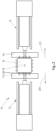
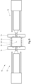
- a machine 10 for processing plastics and other plasticizable masses e.g. an injection molding machine with two injection units 12 and two segments 14, preferably movable segments 14, which e.g. each represent a movable tool plate, for the production of at least one molded part is shown.
- a machine 10 for processing plastics and other plasticizable masses e.g. an injection molding machine with two injection units 12 and two segments 14, preferably movable segments 14, which e.g. each represent a movable tool plate, for the production of at least one molded part is shown.
- only one movable segment 14 and/or only one injection unit 12 is provided.
- two segments 14 are provided, with e.g. one segment 14 being designed as a movable tool plate and one segment 14 as a stationary tool plate.
- a part 16 which can be rotated about at least one axis of rotation 18, e.g. a cube tool, is arranged between the segments 14.
- the rotatable part 16 is attached to and/or on a
- the rotatable part 16 e.g. the cube tool
- melt can be injected into the tool by the injection units 12.
- the cube tool can be rotated by an angle, e.g. by 90°, 180°, 270° or 360°.
- the rotatable part 16 can be rotated by any angle.
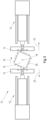
- the segments 14 are each moved in a direction 20, 22.
- the movements take place in opposite directions 20, 22, e.g. to the left and right. If in a further embodiment there is only one movable segment 14, the movement can in principle take place in any direction 20, 22, e.g. to the left or right.
- the movements take place in such a way that the rotatable part 16 is transferred to an open state.
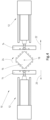
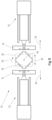
- Fig. 3 the movement of the segments 14 is not yet complete, but the movement of the rotating part 16 in a direction 24, e.g. as a clockwise rotation, already begins.
- the movement of the segments 14 is therefore at least partially superimposed on the movement of the rotating part 16.
- the rotating part 16 already performs its Movement already occurs while the movement of at least one segment 14 is still ongoing. This advantageously results in an optimization with regard to the movements of the machine, in particular the tool movements, and a saving in cycle time as well as a safe, gentle and low-wear operation.
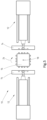
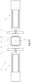
- Fig. 5 the movements of the segments 14 and the rotating part 16 are completed.
- the rotating part 16 is in Fig. 5 by 90° compared to the position in Fig. 1 rotated.
- any rotation around any axis and/or angle is possible, e.g. 90°, 180°, 270°, 360°, -90°, -180°, -270° or -360°. Alternating operation is also possible.
- a machine 10 for processing plastics and other plasticizable masses e.g. an injection molding machine with two injection units 12 and two movable segments 14, each of which represents a movable tool plate, for producing at least one molded part
- a machine 10 for processing plastics and other plasticizable masses e.g. an injection molding machine with two injection units 12 and two movable segments 14, each of which represents a movable tool plate, for producing at least one molded part.
- only one movable segment 14 and/or only one injection unit 12 is provided.
- two segments 14 are provided, with one segment 14 being designed as a movable tool plate and one segment 14 being designed as a stationary tool plate, for example.
- rotatable part 16 eg a cube tool
- melt can be injected into the tool by the injection units 12.
- Fig. 7 the segments 14 are each moved in a direction 20, 22.
- the movements take place in opposite directions 20, 22, e.g. to the left and right.
- the movement can in principle take place in any direction 20, 22, e.g. to the left or right.
- Fig. 2 differs Fig. 7 in that the table 30 is additionally moved in a direction 32, which is preferably parallel to at least one of the directions 20, 22 of the segment 14, e.g. to the left or right.
- Fig. 7 is the movement of the Table 30 at least partially superimposes the movement of the segments 14. In principle, however, in another embodiment it is also conceivable that the segments 14 move and the table does not move or remains stationary.
- Fig. 8 In addition to the movement of the segments 14 and the table 30, the movement of the rotating part 16 in a direction 24, e.g. a clockwise rotation, is also used. Fig. 8 the movement of the segments 14 and/or the movement of the rotatable part 16 is at least partially superimposed on the movement of the table 30.
- Fig. 10 the movements of the segments 14, the table 30 and the rotating part 16 are completed.
- the rotating part 16 is in Fig. 10 by 90° compared to the position in Fig. 6 rotated.
- any rotation around any axis and/or angle is possible, e.g. 90°, 180°, 270° or 360°.
- the movements of the at least one segment 14, the table 30 and/or the rotatable part 16 are at least partially coupled to one another.
- the movements are therefore preferably dependent on one another. For example, it is conceivable to start the movement of the table 30 only after a certain movement time of the segment 14 and/or as soon as the segment 14 has reached a certain position. It is also conceivable that the movement of the rotatable part 16 is only started when the table 30 and/or the segment 14 have reached a certain position and/or have moved for a certain time.
- the coupling can also be staggered.
- the system first waits until the segment 14 has reached a certain position and/or has been moved for a certain time. Then the movement of the table 30 is started. To start the movement of the rotating part 16, it then also waits until the segment 14 and/or the table 30 have reached a certain position and/or have been moved for a certain time.
- the movement of the table 30 is coupled to the movement of the segment 14 until a superimposed braking function intervenes and brakes the table 30 to its final position for this work step.
- the movement of the table 30 is multiplied by a factor less than or equal to one, preferably a factor of 0.1, 0.2, 0.3, 0.4, 0.5, 0.6, 0.7, 0.8, 0.9 or 1.0, compared to the movement of the at least one segment 14.
- the segment 14 and the table 30 start their movement at the same time, e.g. to the left in the direction 20.
- the movement of the table is multiplied by a factor less than or equal to one, so that the change in position of the table 30 is less than the change in position of the segment 14.
- the table 30 and thus the rotatable part 16 are guided along the segment 14 without being able to collide.
- the rotatable part 16 moves away from the segment 14.
- the rotatable part 16 moves away from both segments 14.
- the increasing distance is identical on both sides.
- the coupling is carried out electrically and/or mechanically.
- an electrical coupling for example, the positions of the segment 14, the table 30 and the rotating part 16 can be detected. The respective movements then take place at a correspondingly predetermined position, so that a simple and quick coupling can advantageously be carried out, especially when the rotating part 16 is replaced.
- a mixed coupling is also conceivable.
- the segment 14 could be coupled to the table 30 by means of a mechanical coupling, e.g. a rack, and the coupling to the rotating part 16 could take place electrically.
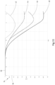
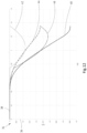
- FIG. 11 A diagram 34 is shown for a further embodiment, wherein an axis 36, e.g. the distance in meters, is plotted against a further axis 38, e.g. the time in seconds.
- a curve 48 describes the position and/or the distance covered by the at least one segment 14 at a specific time. For example, the distance corresponds to a value of approximately -0.45 after about 1.3 seconds.
- the values of the axes 36, 38 are to be understood as examples only.
- a curve 44 describes the translational movement of the rotatable part 16 due to the movement of the movable table 30. One can see there, for example, a factor of approximately 0.5 between the movement of the movable table 30 or the curve 44 and the at least one segment 14 or the curve 48.
- a curve 42 describes the movement of the rotatable part 16, e.g. along the X coordinate.
- a curve 46 the superimposed movement of the rotating part 16 with the movable table 30 along, for example, the X coordinate is shown.
- the curve 46 is obtained by summing the curves 44 and 42. recognizes that initially only the movable table 30 moves until, at about 0.85 seconds, the movement of the rotating part 16 along the X coordinate begins.
- the rotating part 16 leads in Fig. 11 only starts its movement when the gap between the rotating part 16 and the segment 14 is so large that the rotating part 16 fits into the gap and does not collide even in the worst case scenario, eg when rotating by 45°.
- the movement of the rotatable part 16 begins in contrast to Fig. 11 after about 0.75 seconds, which advantageously results in a shorter cycle time.
- the time according to curve 42 for the movement of the rotating part in Fig. 12 less than 1.4 seconds, while the time in Fig. 11 is greater than 1.4 seconds.
- the parameters in Fig. 11 correspond, takes place in Fig. 12 the movement of the rotating part 16 at a time when the gap between the rotating part 16 and the segment 14 is not yet large enough to prevent a collision in the worst case, e.g. with a rotation of 45°.
- the collision is preferably prevented by the segment 14 continuing to move during the movement of the rotating part 16 and thus the gap between the rotating part 16 and the segment 14 increasing so that when the worst case is reached the gap is large enough.
- the movement of the rotatable part 16, e.g. a rotation, is only started when the distance between the segment 14 and the rotatable part 16 is greater than a molded part height 29.
- the molded part height 29 corresponds to the dimension by which the preferably completely demolded molded part protrudes from the rotatable part 16. If, for example, with two segments 14 on both sides, the molded part height 29 is exceeded as a distance from the rotatable part 16, the movement of the rotatable part 16 is initiated.
- the rotatable part 16 begins to rotate while the table 30 and/or the segments 14 move at the same time.
- the movement of the at least one segment 14, the part 16 and/or the table 30 is position-controlled.
- the position control can be carried out with a servo-electric and/or servo-hydraulic drive, e.g. a direct drive or a piston system.
- a drive e.g. a motor rotation angle and a corresponding movement of at least one segment 14, the part 16 and/or the table 30 no linear relationship.
- the movements of the at least one segment 14, the part 16 and/or the table 30 are linked to a mathematical function for position control in order to advantageously realize the most efficient and fastest tool movement possible.
- the mathematical function takes into account the kinematics of the corresponding drive. For example, in a servo-electric drive, the motor rotation angle and the linear movement of the movable tool plate are not linearly related.
- the desired movement form is linked to the kinematics of the drive by means of a mathematical function.
- the movement of the part 16 is position-controlled in at least one angular position about the axis of rotation 18 along a rotational collision curve.
- a mathematical function is stored which describes the diagonal of the cube tool along the rotational movement.
- the rotational collision curve depends on at least one parameter of the part, e.g. the edge length 28 of the rotatable part 16 and/or the molded part height 29.
- the parameters edge length of the rotating part and molded part height can be entered into the control and/or taught. Teaching advantageously results in increased safety, as no collision can occur.
- the machine 10 often has additional peripheral systems, e.g. a robot system and/or a gripper, with which the molded parts are removed, for example.
- the movement of at least one peripheral system e.g. a robot system
- the movement sequences of the robot system can also be coupled with the movements of the table 30 and/or the movement of the rotatable part 16.
- a machine 10 for processing plastics and other plasticizable masses in particular an injection molding machine, is disclosed in a further embodiment, which is arranged, designed and/or constructed to carry out at least one of the previously described methods while achieving the stated advantages.
- a further embodiment forms a computer program product with a program code stored on a computer-readable medium for carrying out at least one of the methods described above while achieving the aforementioned advantages.
Landscapes
- Engineering & Computer Science (AREA)
- Manufacturing & Machinery (AREA)
- Mechanical Engineering (AREA)
- Moulds For Moulding Plastics Or The Like (AREA)
- Injection Moulding Of Plastics Or The Like (AREA)
Claims (11)
- Procédé pour faire tourner une pièce tournante (16) autour d'au moins un axe de rotation (18) d'une machine (10) pour la transformation de matières plastique et d'autres masses plastifiables, en particulier d'une machine de moulage par injection, comportant au moins un segment (14) mobile pour la fabrication d'au moins une pièce moulée, le mouvement du ou des segment(s) (14) étant au moins partiellement superposé au mouvement de la pièce tournante (16), caractérisé en ce que le mouvement de la pièce tournante (16) n'est démarré que lorsque la distance entre le ou les segment(s) (14) et la pièce tournante (16) est supérieure à la hauteur d'une pièce moulée à fabriquer sur la machine (10) et la pièce tournante (16) est appliquée au niveau de et/ou sur une table déplaçable (30) et le mouvement de la table (30) est superposé au moins partiellement au mouvement du ou des segment(s) (14) et/ou au mouvement de la pièce tournante (16) et les mouvements du ou des segment(s) (14), de la table déplaçable (30) et/ou de la pièce tournante (16) sont au moins partiellement couplés les uns aux autre et les mouvement du segment (14), de la table (30) et/ou de la pièce (16) sont dépendants les uns des autres.
- Procédé selon la revendication 1, caractérisé en ce que le mouvement de la table déplaçable (30) est multiplié par un facteur inférieur ou égal à un, de préférence par un facteur de 0,5, par rapport au mouvement du ou des segment(s) (14).
- Procédé selon la revendication 1 ou 2, caractérisé en ce que le couplage est effectué de manière électrique et/ou mécanique.
- Procédé selon l'une des revendications précédentes, caractérisé en ce que le mouvement du ou des segments (14), de la pièce tournante (16) et/ou de la table tournante (30) est réglé en position.
- Procédé selon la revendication 4, caractérisé en que le réglage de la position du mouvement du ou des segments (14), de la pièce tournante (16) et/ou de la table déplaçable (30) et lié à au moins une fonction mathématique.
- Procédé selon la revendication 4 ou 5, caractérisé en ce que le mouvement de la pièce tournante (16) est réglé en position dans au moins une position angulaire autour de l'axe de rotation (18) le long d'une courbe de collision de rotation.
- Procédé selon la revendication 6, caractérisé en ce que la courbe de collision de rotation est dépendante d'au moins un paramètre de la pièce tournante (16).
- Procédé selon la revendication 7, caractérisé en ce que le ou les paramètre(s) de la pièce tournante (16) est pris en compte.
- Procédé selon l'une des revendications précédentes, caractérisé en ce que le mouvement d'au moins un système périphérique avec les mouvements du ou des segment(s) (14), de la table déplaçable (30) et/ou de la partie tournante (16) sont couplés les uns aux autres au moins partiellement.
- Machine (10) pour la transformation de matières plastiques et d'autres masses plastifiables, en particulier, machine de moulage par injection, caractérisée en ce que la machine (10) est configurée, réalisée et/ou construite pour la mise en oeuvre du procédé selon l'une des revendications 1 à 9.
- Produit à programme d'ordinateur avec un code programme, qui est stocké sur un support lisible par un ordinateur, pour la mise en oeuvre du procédé selon l'une des revendications 1 à 9 avec une machine (10) pour la transformation de matières plastiques et d'autres masses plastifiables, en particulier une machine de moulage par injection.
Applications Claiming Priority (2)
| Application Number | Priority Date | Filing Date | Title |
|---|---|---|---|
| DE102021127214.9A DE102021127214A1 (de) | 2021-10-20 | 2021-10-20 | Verfahren zum Drehen eines drehbaren Teils |
| PCT/EP2022/079052 WO2023066969A1 (fr) | 2021-10-20 | 2022-10-19 | Méthode de rotation d'une partie rotative |
Publications (3)
| Publication Number | Publication Date |
|---|---|
| EP4392219A1 EP4392219A1 (fr) | 2024-07-03 |
| EP4392219B1 true EP4392219B1 (fr) | 2024-11-27 |
| EP4392219C0 EP4392219C0 (fr) | 2024-11-27 |
Family
ID=84360401
Family Applications (1)
| Application Number | Title | Priority Date | Filing Date |
|---|---|---|---|
| EP22808664.1A Active EP4392219B1 (fr) | 2021-10-20 | 2022-10-19 | Méthode de rotation d'une partie rotative |
Country Status (6)
| Country | Link |
|---|---|
| US (1) | US20250187244A1 (fr) |
| EP (1) | EP4392219B1 (fr) |
| CN (1) | CN118434554A (fr) |
| CA (1) | CA3235042A1 (fr) |
| DE (1) | DE102021127214A1 (fr) |
| WO (1) | WO2023066969A1 (fr) |
Family Cites Families (6)
| Publication number | Priority date | Publication date | Assignee | Title |
|---|---|---|---|---|
| DE19733667C2 (de) * | 1997-08-04 | 2002-02-07 | Ferromatik Milacron Maschb Gmb | Vorrichtung zur Herstellung von Spritzgießartikeln aus mindestens zwei Kunststoffschmelzen |
| AU2003218841B2 (en) * | 2002-05-17 | 2006-06-22 | Husky Injection Molding Systems Ltd. | Post mold cooling apparatus and method having rotational and transverse movement |
| DK1725386T3 (da) * | 2004-02-10 | 2011-02-21 | Foboha Gmbh Formenbau | Fremgangsmåde og apparat til sprøjtestøbning og montering af kunststofdele |
| CN102470580B (zh) * | 2009-12-07 | 2014-07-09 | 三菱重工塑胶科技有限公司 | 双材成型用注塑成型机 |
| CH707711A2 (de) | 2013-03-15 | 2014-09-15 | Foboha Gmbh | Haltevorrichtung für einen drehbaren Formmittelteil in einer Spritzgiessvorrichtung. |
| CH714057A1 (de) | 2017-08-11 | 2019-02-15 | Alpla Werke Alwin Lehner Gmbh & Co Kg | Montagevorrichtung für Formwerkzeugteile eines Spritzgiesswerkzeugs, Spritzgiesswerkzeug und Spritzgiessmaschine. |
-
2021
- 2021-10-20 DE DE102021127214.9A patent/DE102021127214A1/de not_active Withdrawn
-
2022
- 2022-10-19 CA CA3235042A patent/CA3235042A1/fr active Pending
- 2022-10-19 US US18/702,350 patent/US20250187244A1/en active Pending
- 2022-10-19 CN CN202280084419.2A patent/CN118434554A/zh active Pending
- 2022-10-19 EP EP22808664.1A patent/EP4392219B1/fr active Active
- 2022-10-19 WO PCT/EP2022/079052 patent/WO2023066969A1/fr not_active Ceased
Also Published As
| Publication number | Publication date |
|---|---|
| CA3235042A1 (fr) | 2023-04-27 |
| CN118434554A (zh) | 2024-08-02 |
| EP4392219A1 (fr) | 2024-07-03 |
| EP4392219C0 (fr) | 2024-11-27 |
| WO2023066969A1 (fr) | 2023-04-27 |
| DE102021127214A1 (de) | 2023-04-20 |
| US20250187244A1 (en) | 2025-06-12 |
Similar Documents
| Publication | Publication Date | Title |
|---|---|---|
| EP1673208B1 (fr) | Machine de moulage par injection horizontale pourvue d'un dispositif tournant | |
| EP2263855B1 (fr) | Machine de formage par soufflage entraînée de manière électrique et le procédé | |
| DE2659655B2 (de) | Spritzblasvorrichtung zum Herstellen von Hohlkörpern aus thermoplastischem Kunststoff | |
| DE3856197T2 (de) | Rotation-Formmaschine | |
| EP1174242A2 (fr) | Procédé et dispositif pour mouler par injection des articles en matière plastique à plusieurs composants | |
| EP3655225B1 (fr) | Unite de fermeture de moule pour machine de moulage par injection | |
| EP0767760B2 (fr) | Procede de fabrication de pieces moulees en verre par moulage par compression et dispositif particulierement approprie pour la mise en oeuvre de ce procede | |
| EP0074473A1 (fr) | Procédé et dispositif pour la fabrication de pièces de forme ou des objets en matière plastique | |
| AT525769B1 (de) | Schließeinheit für eine Formgebungsmaschine | |
| EP4392219B1 (fr) | Méthode de rotation d'une partie rotative | |
| DE69028634T2 (de) | Formschliesssystem | |
| DE2846989A1 (de) | Verfahren und vorrichtung zur herstellung eines behaelters aus kunststoff mittels spritzblasformen | |
| EP1053857B1 (fr) | Machine à souffler pour soufflage avec bavures réduites | |
| DE4418452A1 (de) | Metallgießform und Metall-Formgießvorrichtung | |
| DE102011015943B4 (de) | Verriegelungsvorrichtung für Säulen einer Kunststoffverarbeitungsmaschine | |
| EP1613461B1 (fr) | Ensemble moule | |
| WO2015121132A1 (fr) | Dispositif de traitement et dispositif de moulage par injection | |
| EP1954468A1 (fr) | Procede et systeme pour post-traitement de preformes | |
| EP1048435A1 (fr) | Procédé et appareil de moulage par injection-soufflage | |
| WO2014075883A1 (fr) | Module retourneur pour machine de moulage par injection | |
| WO2012055736A1 (fr) | Outil de moulage par injection et procédé de fabrication de pièces moulées multicomposantes | |
| DE2535367A1 (de) | Einrichtung und verfahren zum blasformen hohler gegenstaende | |
| AT8677U1 (de) | Form für spritzgiesswerkzeuge | |
| DE102011116148A1 (de) | Schließeinheit für eine Spritzgießmaschine | |
| DE102012006380A1 (de) | Saugblasverfahren |
Legal Events
| Date | Code | Title | Description |
|---|---|---|---|
| STAA | Information on the status of an ep patent application or granted ep patent |
Free format text: STATUS: UNKNOWN |
|
| STAA | Information on the status of an ep patent application or granted ep patent |
Free format text: STATUS: THE INTERNATIONAL PUBLICATION HAS BEEN MADE |
|
| PUAI | Public reference made under article 153(3) epc to a published international application that has entered the european phase |
Free format text: ORIGINAL CODE: 0009012 |
|
| STAA | Information on the status of an ep patent application or granted ep patent |
Free format text: STATUS: REQUEST FOR EXAMINATION WAS MADE |
|
| 17P | Request for examination filed |
Effective date: 20240326 |
|
| AK | Designated contracting states |
Kind code of ref document: A1 Designated state(s): AL AT BE BG CH CY CZ DE DK EE ES FI FR GB GR HR HU IE IS IT LI LT LU LV MC ME MK MT NL NO PL PT RO RS SE SI SK SM TR |
|
| GRAP | Despatch of communication of intention to grant a patent |
Free format text: ORIGINAL CODE: EPIDOSNIGR1 |
|
| STAA | Information on the status of an ep patent application or granted ep patent |
Free format text: STATUS: GRANT OF PATENT IS INTENDED |
|
| DAV | Request for validation of the european patent (deleted) | ||
| DAX | Request for extension of the european patent (deleted) | ||
| INTG | Intention to grant announced |
Effective date: 20240705 |
|
| GRAS | Grant fee paid |
Free format text: ORIGINAL CODE: EPIDOSNIGR3 |
|
| GRAA | (expected) grant |
Free format text: ORIGINAL CODE: 0009210 |
|
| STAA | Information on the status of an ep patent application or granted ep patent |
Free format text: STATUS: THE PATENT HAS BEEN GRANTED |
|
| AK | Designated contracting states |
Kind code of ref document: B1 Designated state(s): AL AT BE BG CH CY CZ DE DK EE ES FI FR GB GR HR HU IE IS IT LI LT LU LV MC ME MK MT NL NO PL PT RO RS SE SI SK SM TR |
|
| REG | Reference to a national code |
Ref country code: GB Ref legal event code: FG4D Free format text: NOT ENGLISH |
|
| REG | Reference to a national code |
Ref country code: CH Ref legal event code: EP |
|
| REG | Reference to a national code |
Ref country code: IE Ref legal event code: FG4D Free format text: LANGUAGE OF EP DOCUMENT: GERMAN |
|
| REG | Reference to a national code |
Ref country code: DE Ref legal event code: R096 Ref document number: 502022002258 Country of ref document: DE |
|
| U01 | Request for unitary effect filed |
Effective date: 20241223 |
|
| U07 | Unitary effect registered |
Designated state(s): AT BE BG DE DK EE FI FR IT LT LU LV MT NL PT RO SE SI Effective date: 20250114 |
|
| PG25 | Lapsed in a contracting state [announced via postgrant information from national office to epo] |
Ref country code: HR Free format text: LAPSE BECAUSE OF FAILURE TO SUBMIT A TRANSLATION OF THE DESCRIPTION OR TO PAY THE FEE WITHIN THE PRESCRIBED TIME-LIMIT Effective date: 20241127 Ref country code: IS Free format text: LAPSE BECAUSE OF FAILURE TO SUBMIT A TRANSLATION OF THE DESCRIPTION OR TO PAY THE FEE WITHIN THE PRESCRIBED TIME-LIMIT Effective date: 20250327 |
|
| PG25 | Lapsed in a contracting state [announced via postgrant information from national office to epo] |
Ref country code: ES Free format text: LAPSE BECAUSE OF FAILURE TO SUBMIT A TRANSLATION OF THE DESCRIPTION OR TO PAY THE FEE WITHIN THE PRESCRIBED TIME-LIMIT Effective date: 20241127 |
|
| PG25 | Lapsed in a contracting state [announced via postgrant information from national office to epo] |
Ref country code: NO Free format text: LAPSE BECAUSE OF FAILURE TO SUBMIT A TRANSLATION OF THE DESCRIPTION OR TO PAY THE FEE WITHIN THE PRESCRIBED TIME-LIMIT Effective date: 20250227 |
|
| PG25 | Lapsed in a contracting state [announced via postgrant information from national office to epo] |
Ref country code: GR Free format text: LAPSE BECAUSE OF FAILURE TO SUBMIT A TRANSLATION OF THE DESCRIPTION OR TO PAY THE FEE WITHIN THE PRESCRIBED TIME-LIMIT Effective date: 20250228 |
|
| PG25 | Lapsed in a contracting state [announced via postgrant information from national office to epo] |
Ref country code: PL Free format text: LAPSE BECAUSE OF FAILURE TO SUBMIT A TRANSLATION OF THE DESCRIPTION OR TO PAY THE FEE WITHIN THE PRESCRIBED TIME-LIMIT Effective date: 20241127 |
|
| PG25 | Lapsed in a contracting state [announced via postgrant information from national office to epo] |
Ref country code: RS Free format text: LAPSE BECAUSE OF FAILURE TO SUBMIT A TRANSLATION OF THE DESCRIPTION OR TO PAY THE FEE WITHIN THE PRESCRIBED TIME-LIMIT Effective date: 20250227 |
|
| PG25 | Lapsed in a contracting state [announced via postgrant information from national office to epo] |
Ref country code: SM Free format text: LAPSE BECAUSE OF FAILURE TO SUBMIT A TRANSLATION OF THE DESCRIPTION OR TO PAY THE FEE WITHIN THE PRESCRIBED TIME-LIMIT Effective date: 20241127 |
|
| PG25 | Lapsed in a contracting state [announced via postgrant information from national office to epo] |
Ref country code: SK Free format text: LAPSE BECAUSE OF FAILURE TO SUBMIT A TRANSLATION OF THE DESCRIPTION OR TO PAY THE FEE WITHIN THE PRESCRIBED TIME-LIMIT Effective date: 20241127 |
|
| PG25 | Lapsed in a contracting state [announced via postgrant information from national office to epo] |
Ref country code: CZ Free format text: LAPSE BECAUSE OF FAILURE TO SUBMIT A TRANSLATION OF THE DESCRIPTION OR TO PAY THE FEE WITHIN THE PRESCRIBED TIME-LIMIT Effective date: 20241127 |
|
| PLBE | No opposition filed within time limit |
Free format text: ORIGINAL CODE: 0009261 |
|
| STAA | Information on the status of an ep patent application or granted ep patent |
Free format text: STATUS: NO OPPOSITION FILED WITHIN TIME LIMIT |
|
| REG | Reference to a national code |
Ref country code: CH Ref legal event code: L10 Free format text: ST27 STATUS EVENT CODE: U-0-0-L10-L00 (AS PROVIDED BY THE NATIONAL OFFICE) Effective date: 20251008 |
|
| U20 | Renewal fee for the european patent with unitary effect paid |
Year of fee payment: 4 Effective date: 20250917 |
|
| REG | Reference to a national code |
Ref country code: CH Ref legal event code: U11 Free format text: ST27 STATUS EVENT CODE: U-0-0-U10-U11 (AS PROVIDED BY THE NATIONAL OFFICE) Effective date: 20251101 |
|
| 26N | No opposition filed |
Effective date: 20250828 |
|
| PGFP | Annual fee paid to national office [announced via postgrant information from national office to epo] |
Ref country code: CH Payment date: 20251101 Year of fee payment: 4 |