EP4392310B1 - Procédé pour commander un véhicule à l'intérieur d'un site confiné, unité de commande et véhicule - Google Patents
Procédé pour commander un véhicule à l'intérieur d'un site confiné, unité de commande et véhicule Download PDFInfo
- Publication number
- EP4392310B1 EP4392310B1 EP22757947.1A EP22757947A EP4392310B1 EP 4392310 B1 EP4392310 B1 EP 4392310B1 EP 22757947 A EP22757947 A EP 22757947A EP 4392310 B1 EP4392310 B1 EP 4392310B1
- Authority
- EP
- European Patent Office
- Prior art keywords
- vehicle
- steering
- path
- sbl
- automated
- Prior art date
- Legal status (The legal status is an assumption and is not a legal conclusion. Google has not performed a legal analysis and makes no representation as to the accuracy of the status listed.)
- Active
Links
Images

Classifications
-
- B—PERFORMING OPERATIONS; TRANSPORTING
- B62—LAND VEHICLES FOR TRAVELLING OTHERWISE THAN ON RAILS
- B62D—MOTOR VEHICLES; TRAILERS
- B62D11/00—Steering non-deflectable wheels; Steering endless tracks or the like
- B62D11/02—Steering non-deflectable wheels; Steering endless tracks or the like by differentially driving ground-engaging elements on opposite vehicle sides
- B62D11/06—Steering non-deflectable wheels; Steering endless tracks or the like by differentially driving ground-engaging elements on opposite vehicle sides by means of a single main power source
- B62D11/08—Steering non-deflectable wheels; Steering endless tracks or the like by differentially driving ground-engaging elements on opposite vehicle sides by means of a single main power source using brakes or clutches as main steering-effecting means
-
- B—PERFORMING OPERATIONS; TRANSPORTING
- B60—VEHICLES IN GENERAL
- B60T—VEHICLE BRAKE CONTROL SYSTEMS OR PARTS THEREOF; BRAKE CONTROL SYSTEMS OR PARTS THEREOF, IN GENERAL; ARRANGEMENT OF BRAKING ELEMENTS ON VEHICLES IN GENERAL; PORTABLE DEVICES FOR PREVENTING UNWANTED MOVEMENT OF VEHICLES; VEHICLE MODIFICATIONS TO FACILITATE COOLING OF BRAKES
- B60T8/00—Arrangements for adjusting wheel-braking force to meet varying vehicular or ground-surface conditions, e.g. limiting or varying distribution of braking force
- B60T8/17—Using electrical or electronic regulation means to control braking
- B60T8/1701—Braking or traction control means specially adapted for particular types of vehicles
- B60T8/1708—Braking or traction control means specially adapted for particular types of vehicles for lorries or tractor-trailer combinations
-
- B—PERFORMING OPERATIONS; TRANSPORTING
- B60—VEHICLES IN GENERAL
- B60T—VEHICLE BRAKE CONTROL SYSTEMS OR PARTS THEREOF; BRAKE CONTROL SYSTEMS OR PARTS THEREOF, IN GENERAL; ARRANGEMENT OF BRAKING ELEMENTS ON VEHICLES IN GENERAL; PORTABLE DEVICES FOR PREVENTING UNWANTED MOVEMENT OF VEHICLES; VEHICLE MODIFICATIONS TO FACILITATE COOLING OF BRAKES
- B60T8/00—Arrangements for adjusting wheel-braking force to meet varying vehicular or ground-surface conditions, e.g. limiting or varying distribution of braking force
- B60T8/17—Using electrical or electronic regulation means to control braking
- B60T8/1755—Brake regulation specially adapted to control the stability of the vehicle, e.g. taking into account yaw rate or transverse acceleration in a curve
-
- B—PERFORMING OPERATIONS; TRANSPORTING
- B60—VEHICLES IN GENERAL
- B60T—VEHICLE BRAKE CONTROL SYSTEMS OR PARTS THEREOF; BRAKE CONTROL SYSTEMS OR PARTS THEREOF, IN GENERAL; ARRANGEMENT OF BRAKING ELEMENTS ON VEHICLES IN GENERAL; PORTABLE DEVICES FOR PREVENTING UNWANTED MOVEMENT OF VEHICLES; VEHICLE MODIFICATIONS TO FACILITATE COOLING OF BRAKES
- B60T8/00—Arrangements for adjusting wheel-braking force to meet varying vehicular or ground-surface conditions, e.g. limiting or varying distribution of braking force
- B60T8/17—Using electrical or electronic regulation means to control braking
- B60T8/1755—Brake regulation specially adapted to control the stability of the vehicle, e.g. taking into account yaw rate or transverse acceleration in a curve
- B60T8/17551—Brake regulation specially adapted to control the stability of the vehicle, e.g. taking into account yaw rate or transverse acceleration in a curve determining control parameters related to vehicle stability used in the regulation, e.g. by calculations involving measured or detected parameters
-
- B—PERFORMING OPERATIONS; TRANSPORTING
- B60—VEHICLES IN GENERAL
- B60W—CONJOINT CONTROL OF VEHICLE SUB-UNITS OF DIFFERENT TYPE OR DIFFERENT FUNCTION; CONTROL SYSTEMS SPECIALLY ADAPTED FOR HYBRID VEHICLES; ROAD VEHICLE DRIVE CONTROL SYSTEMS FOR PURPOSES NOT RELATED TO THE CONTROL OF A PARTICULAR SUB-UNIT
- B60W30/00—Purposes of road vehicle drive control systems not related to the control of a particular sub-unit, e.g. of systems using conjoint control of vehicle sub-units
- B60W30/06—Automatic manoeuvring for parking
-
- B—PERFORMING OPERATIONS; TRANSPORTING
- B62—LAND VEHICLES FOR TRAVELLING OTHERWISE THAN ON RAILS
- B62D—MOTOR VEHICLES; TRAILERS
- B62D15/00—Steering not otherwise provided for
- B62D15/02—Steering position indicators ; Steering position determination; Steering aids
- B62D15/027—Parking aids, e.g. instruction means
- B62D15/0285—Parking performed automatically
-
- G—PHYSICS
- G05—CONTROLLING; REGULATING
- G05D—SYSTEMS FOR CONTROLLING OR REGULATING NON-ELECTRIC VARIABLES
- G05D1/00—Control of position, course, altitude or attitude of land, water, air or space vehicles, e.g. using automatic pilots
- G05D1/02—Control of position or course in two dimensions
- G05D1/021—Control of position or course in two dimensions specially adapted to land vehicles
- G05D1/0276—Control of position or course in two dimensions specially adapted to land vehicles using signals provided by a source external to the vehicle
- G05D1/028—Control of position or course in two dimensions specially adapted to land vehicles using signals provided by a source external to the vehicle using a RF signal
- G05D1/0282—Control of position or course in two dimensions specially adapted to land vehicles using signals provided by a source external to the vehicle using a RF signal generated in a local control room
-
- G—PHYSICS
- G08—SIGNALLING
- G08G—TRAFFIC CONTROL SYSTEMS
- G08G1/00—Traffic control systems for road vehicles
- G08G1/16—Anti-collision systems
- G08G1/164—Centralised systems, e.g. external to vehicles
-
- G—PHYSICS
- G08—SIGNALLING
- G08G—TRAFFIC CONTROL SYSTEMS
- G08G1/00—Traffic control systems for road vehicles
- G08G1/16—Anti-collision systems
- G08G1/168—Driving aids for parking, e.g. acoustic or visual feedback on parking space
-
- B—PERFORMING OPERATIONS; TRANSPORTING
- B62—LAND VEHICLES FOR TRAVELLING OTHERWISE THAN ON RAILS
- B62D—MOTOR VEHICLES; TRAILERS
- B62D9/00—Steering deflectable wheels not otherwise provided for
- B62D9/005—Emergency systems using brakes for steering
Definitions
- the invention relates to a method for controlling a vehicle, in particular a commercial vehicle, on a closed site, in particular a depot, a control unit for carrying out the method and a vehicle.
- Vehicles, especially commercial vehicles, that do not have an active automated steering system can only be integrated into an autonomously managed depot or freight forwarding yard as a closed area to a limited extent, as they cannot follow a predefined path from a starting area to a destination area fully automatically. This is only possible if a driver or operating personnel assumes the driving function, especially the steering function, which means that more personnel than necessary or desired are involved in the depot. However, this is undesirable for autonomously operating vehicles or depots. Retrofitting an active automated steering system is also expensive.
- EP 3 293 064 A1 and EP 3 293 065 A1 It is also intended to switch back and forth between steering via an automated steering system and steering via steering braking via a switching module, whereby the Automatic corrections should be carried out by the respective steering when carrying out autonomous driving maneuvers as part of a lane keeping or lane change assistance system.
- the DE102016116857A1 discloses a system for operating a driverless commercial vehicle in a restricted area, the restricted area having an entrance, an exit, and a predetermined destination.
- the system comprises a transfer module for transferring control of the commercial vehicle at the entrance from the driver of the commercial vehicle to the system, and at the exit and further from the system to the driver of the commercial vehicle.
- the system further comprises a movement module for autonomously moving the commercial vehicle from the entrance to the predetermined destination and from the predetermined destination to the exit, and an execution module for autonomously performing an action on the commercial vehicle while the commercial vehicle is at the predetermined destination to change a state of the commercial vehicle through the action.
- the object of the invention is to provide a method for controlling a vehicle on a closed site, which allows any vehicle to access an automated site without great effort.
- the object of the invention is also to provide a control unit and a vehicle.
- a method for controlling a vehicle on a closed site, in particular on a depot, wherein the vehicle has a control unit which is designed to automatically control a braking system and a drive system in the vehicle in order to move the vehicle automatically, i.e. driverless or autonomously, along a defined path.
- the "availability" includes both the presence and the functionality of such an automatically controllable steering system, which is thus initially determined.
- the determination preferably takes place in the starting area of the closed area, for example, after arriving at the closed premises.
- control unit for carrying out the method and a vehicle with the control unit are also provided.
- a steering brake function is thus implemented, allowing the vehicle, which in this case has no possibility of automated adjustment of the steering angle via a conventional steering system, to be steered automatically on the enclosed site.
- This steering is enabled via the steering brake control signal in that the brakes are controlled individually for each wheel when the braking system is automatically activated using this steering brake control signal, so that a differential brake pressure develops between the wheels of the same vehicle axle.
- This differential brake pressure results in a steering torque when the steering roll radius of the steered wheels in question is positive, whereupon a steering angle related to the differential brake pressure is established at the wheels of the steered vehicle axle.
- a vehicle with a defective or non-existent automated steering system can still be integrated into an automated, enclosed site, in particular a depot or a freight forwarding yard, without the need for manual control. which is undesirable on such automated farms for reasons of mutual and safe coordination.
- the path is defined in such a way that the steering angle at the wheels of the steered vehicle axle remains below a defined limit steering angle, for example, below 20°, during automated control of the braking system with the steering brake control signals to move the vehicle along the path.
- a defined limit steering angle for example, below 20°
- This can be taken into account when planning or defining the path, for example by specifying fewer curve sections and/or correspondingly smaller bends that are traversed with the maximum limit steering angle in the existing curve sections between the starting area and the destination area.
- the path is further defined by a management system of the enclosed area or by a control unit in the vehicle.
- the management system can access the infrastructure of the area to achieve more reliable path planning, or path planning can be performed autonomously from the vehicle, for example, if a management system is currently unavailable or not present.
- vehicle information relating to the vehicle is transmitted to the management system of the enclosed area for determining the path, so that the management system can determine in advance whether or not an automated steering system is available in the vehicle.
- a wireless network of the enclosed area can be used, for example. If an automated steering system is available, path planning can be carried out as usual without the additional restrictions resulting from steering braking. If no automated steering system is available, which can be determined from the vehicle information provided by the management system, path planning is carried out as described above. The management system can therefore automatically initiate the appropriate path planning routine depending on the detected vehicle equipment.
- the path and/or the target area is/are determined depending on obstacles and/or other vehicles on the enclosed terrain. It can be taken into account that, due to limitations such as the adjustable steering angle due to the steering brake function, certain maneuvers are more complex or even impossible. It should also be considered that the vehicle must be moving for a steering movement. The path and the target area can be determined or selected accordingly.
- a check is carried out to determine whether the vehicle mass of the vehicle falls below or exceeds a specified limit mass, for example 31 t. This can prevent excessive wear, which can occur with particularly heavy vehicles. It is preferably provided that release for the automated generation of the steering brake control signal and/or for the automated control of the vehicle's braking system with the steering brake control signal, i.e. steering braking, only occurs when the vehicle mass falls below the limit mass. Steering braking is therefore suppressed and the vehicle must move to the target area, if necessary manually controlled, until, for example, after unloading, the vehicle mass is again below the limit mass.
- a brake temperature of at least the brakes that are automatically controlled is monitored, wherein an automated generation of the steering brake control signal and/or an automated control of the vehicle's braking system with the steering brake control signal, i.e., a steering braking, is only maintained if the brake temperature is below a temperature limit.
- This allows for additional wear monitoring, which can be derived from an increased brake temperature.
- a steering brake period is determined, which indicates how long an automated control of the braking system with the steering brake control signal for automatically following the path via the steering brake has taken place, wherein an automated generation of the steering brake control signal and/or an automated control of the vehicle's braking system with the steering brake control signal, i.e. a steering brake, is only maintained until the steering brake period exceeds a specified limit period.
- an automated generation of the steering brake control signal and/or an automated control of the vehicle's braking system with the steering brake control signal i.e. a steering brake
- wear can also be estimated based solely on the steering brake period.
- the target area also includes a loading ramp, unloading area, or parking space.
- a loading ramp unloading area, or parking space. This allows for flexible use of the method, which can be applied not only at a depot or freight forwarding yard, but also at a rest area or port area.
- Figure 1a shows schematically a vehicle 1, which consists of a towing vehicle 1a and a trailer 1b coupled to it and which is arranged according to Fig. 1 is located on an enclosed site 2, for example a depot 2a (freight forwarding yard) or a rest area or a port area.
- the enclosed site 2a is controlled or coordinated by a management system 3, which ensures in particular that arriving vehicles 1 are guided from a starting area 4 along a defined path P to a defined destination area 5, for example to a defined loading ramp 5a.
- the path P is planned or determined by the management system 3 depending on certain vehicle information I1, which may contain, for example, a load, an authorization, a destination, vehicle equipment, etc., and transmitted via any communication system 6, for example a stationary and local wireless network 6a (e.g., WLAN), to a vehicle control unit 10 in the relevant vehicle 1.
- vehicle control unit 10 then ensures that the vehicle 1 moves automatically along the specified path P to the target area 5 by controlling the corresponding system components of the vehicle 1 via control signals.
- the path P is determined in particular depending on the vehicle equipment, from which it can be derived which system components the Vehicle control unit 10 can be controlled in order to follow the specified path P. This makes it possible to take into account the manner in which autonomous control of the vehicle 1 on the enclosed site 2 is possible. If, for example, there is no automatically controllable steering system 20 available in the vehicle 1 via which a steering angle d of the wheels 7 of a steerable vehicle axle 8, in particular the front axle of the vehicle 1, can be actively adjusted, this must be taken into account accordingly when planning the path P by the management system 3, so that such a vehicle 1 can also be integrated into the automated process at the depot 2a.
- the management system 3 uses the vehicle information I1 to determine whether an automatically controllable steering system 20 is available, i.e., whether it is present in the vehicle 1 and is therefore functional. If this is the case, the path P can be planned by the management system 3 as usual such that the vehicle 1 is moved along the path P by automated control of the automatically controllable steering system 20 via steering control signals SL, the automatically controllable drive system 30 via drive control signals SA, and the automatically controllable braking system 40 via braking control signals SB.
- the respective control signals SA, SB, SL are also automatically generated by the control unit 10 depending on the path P.
- the infrastructure on the depot 2a is used, i.e., obstacles H and other stationary or moving vehicles 100 are detected and taken into account.
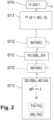
- the management system 3 takes into account in a first step ST1 that steering of the vehicle 1 by setting a specific steering angle d on the wheels 7 of the steered vehicle axle 8 can only take place within the framework of a steering brake function.
- the initial check step ST0 and the first step ST1 for determining the path P can also be carried out by the control unit 10 itself, whereby instead of relying on the infrastructure of the depot 2a, a sensor system 50 with the sensors in the vehicle 1 is used to plan and determine the path P.
- the vehicle information I1 in particular the vehicle equipment, is known to the control unit 10 itself, so that the planning and determination of the path P can also take place from this perspective.
- the control unit 10 will then, in a subsequent second step ST2, generate steering brake control signals SBL instead of the steering control signals SL for the automated steering of the vehicle 1 in order to influence the steering angle d of the wheels 7 of the steered vehicle axle 8, wherein at the same time a drive control signal SA is also generated, since steering braking is only possible while the vehicle 1 is traveling (forward or backward).
- These generated steering brake control signals SBL and drive control signals SA are then automatically transmitted to the braking system 40 and the drive system 30, respectively, in a third step ST3, whereupon, when the vehicle 1 is moving, a specific steering torque L results on the vehicle 1 through a wheel-individual control of the brakes 9, in particular on the wheels 7 of the steered vehicle axle 8, which, due to the positive steering roll radius on the wheels 7 of the steered vehicle axle 8, ensures that these wheels 7 are turned by a specific steering angle d and thus that the driven vehicle 1 is steered.
- the steering brake control signals SBL are generated in such a way that a differential brake pressure dP is built up at the wheels 7 of the steered vehicle axle 8 by individually controlling the brakes 9 for each wheel, whereby the brake pressure at one of the brakes 9 of the steered vehicle axle 8 is ideally zero in order not to place unnecessary strain on the brakes 9.
- This differential brake pressure dP corresponds, via the built-up steering torque L (and via the positive steering roll radius), to a resulting steering angle d at the wheels 7 of the steered vehicle axle 8, which in turn automatically implements the steering command at the respective position of the path P.
- the specified path P can be followed by automated control of the braking system 40 with the steering brake control signal SBL and of the drive system 30 with the drive signals SA.
- Braking or driving of the vehicle 1 is achieved by superimposing the drive control signal SA or the brake control signal SB with the steering brake control signal SBL.
- vehicle 1 can be steered less effectively by steering braking or only with a limit steering angle dG of, for example, 20°, this must be taken into account when defining path P by management system 3 in the first step ST1.
- a limit steering angle dG of 20° can also be achieved by the described steering braking, this only results in increased wear on the respective brakes 9 controlled. It must therefore also be taken into account that increased wear on the respective brakes 9 controlled for steering braking occurs due to steering braking.
- path P must be defined, for example, such that it has only a few curve sections KA and/or only curve sections KA with a slight curvature K occur, so that the set differential brake pressure dP and accordingly also the absolute brake pressures at the respective brakes 9 are lower.
- the definition of the target area 5, where, for example, a load is to be picked up or dropped off may also need to be taken into account.
- a vehicle 1 without an automatically controllable steering system 30 can only maneuver to a free loading ramp 5a between two loading ramps 5a already occupied by other vehicles 100 with great effort and with a large number of curve sections KA, relying on steering braking as described above. Therefore, in this situation, path P with a correspondingly different loading ramp 5a should be selected as the target area 5, where fewer curve sections KA and/or curve sections KA with a smaller curvature K are necessary.
- a vehicle mass M of vehicle 1 can additionally be detected, e.g., from pressure information from an air suspension and/or another mass estimate, in order to enable the subsequent automated control of vehicle 1 depending thereon.
- a limit mass MG of, for example, 31 t. Only if the limit mass MG is undershot does the automated generation of the steering brake control signal SBL and/or the automated control of the braking system 30 with the steering brake control signal SBL subsequently occur in steps ST2 or ST3.
- the steering brake function can be permanently enabled, with the steering brake function being suppressed by control unit 10 if the limit mass MG is exceeded.
- a temperature sensor 51 is arranged on the brakes 9. If a brake temperature T9 of individual brakes 9 exceeds a temperature limit value TG, the enable for the automated generation of the steering brake control signal SBL and/or for the automated control of the braking system 30 with the steering brake control signal SBL is revoked in steps ST2 or ST3, or the steering brake function is suppressed.
- a steering brake period tBL can also be measured, within which the brakes 9 are activated to implement the steering brake function, for example, by an automated function in the braking system 30 and/or by the control unit 10. If a limit period tG is exceeded, regardless of the level of the brake temperature T9, it is provided that an enable for the automated generation of the steering brake control signal SBL and/or for the automated control of the automated braking system 30 with the steering brake control signal SBL is withdrawn in steps ST2 or ST3, or the steering brake function is suppressed. This prevents excessive wear, regardless of the brake temperature T9.
- the path P can be traveled automatically, wherein the control unit 10 can also monitor this automated journey accordingly by using a sensor system 50 with the corresponding sensors in the vehicle 1, for example by carrying out an actual/target comparison of the position of the vehicle 1 and/or obstacle detection.
- the respective task can be carried out, e.g. loading, unloading, service activities, etc., before the vehicle 1 subsequently moves again on a predetermined path P to another target area or back to the original starting area 4 to leave the depot 2a.
- the method can also be carried out at a rest area as a closed area 2, whereby the driver drops off the vehicle 1 at the rest area entrance (starting area 4) and the vehicle 1 is then maneuvered autonomously under steering braking into a free parking space 16 (target area 5) which can be reached with the steering braking function.
Landscapes
- Engineering & Computer Science (AREA)
- Transportation (AREA)
- Mechanical Engineering (AREA)
- Chemical & Material Sciences (AREA)
- Combustion & Propulsion (AREA)
- Physics & Mathematics (AREA)
- General Physics & Mathematics (AREA)
- Automation & Control Theory (AREA)
- Aviation & Aerospace Engineering (AREA)
- Radar, Positioning & Navigation (AREA)
- Remote Sensing (AREA)
- Regulating Braking Force (AREA)
- Steering Control In Accordance With Driving Conditions (AREA)
Claims (17)
- Procédé permettant la commande d'un véhicule (1) dans une enceinte fermée (2), en particulier dans un dépôt (2a), dans lequel le véhicule (1) présente une unité de commande (10) configurée pour commander de manière automatisée un système de freinage (30) et un système d'entraînement (40) dans le véhicule (1) afin de déplacer le véhicule (1) de manière automatisée le long d'une trajectoire (P) définie,
dans lequel, après avoir constaté l'absence de système de direction (20) dans le véhicule (1), lequel système de direction peut être commandé par l'intermédiaire de signaux de commande de direction (SL) générés de manière automatisée afin d'influencer de manière automatisée (ST0) un angle de direction (d) de roues (7) d'un essieu de véhicule (8) dirigé du véhicule (1), au moins les étapes suivantes sont exécutées :- définition d'une trajectoire (P) entre une zone de départ (4) et une zone d'arrivée (5) définie dans l'enceinte fermée (2) (ST1) ;- génération de signaux de commande d'entraînement (SA) et de signaux de commande de freinage de direction (SBL) de telle sorte que, lors d'une commande automatisée ultérieure du système d'entraînement (40) et du système de freinage (30) avec lesdits signaux de commande (SA, SBL), le véhicule (1) se déplace depuis la zone de départ (4) le long de la trajectoire (P) dans la zone d'arrivée (5) définie et l'angle de direction (d) varie (ST3) uniquement en raison d'une commande automatisée des freins (9) du système de freinage (30). - Procédé selon la revendication 1, caractérisé en ce que la trajectoire (P) est définie de telle sorte que l'angle de direction (d) au niveau des roues (7) de l'essieu de véhicule (8) dirigé reste inférieur à un angle de direction limite (dG) défini lors d'une commande automatisée du système de freinage (30) avec les signaux de commande de freinage de direction (SBL) pour le déplacement du véhicule (1) le long de la trajectoire (P).
- Procédé selon la revendication 2, caractérisé en ce que l'angle de direction limite (dG) est de 20°.
- Procédé selon l'une des revendications précédentes,
caractérisé en ce que la trajectoire (P) est définie par un système de gestion (3) de l'enceinte fermée (2) ou sur une unité de commande (10) dans le véhicule (1). - Procédé selon la revendication 4, caractérisé en ce que des informations de véhicule (11) concernant le véhicule (1) sont transmises au système de gestion (3) de l'enceinte fermée (2) pour la définition de la trajectoire (P) de sorte que le système de gestion (3) peut constater au préalable si un système de direction (20) pouvant être commandé de manière automatisée est présent dans le véhicule (1).
- Procédé selon l'une des revendications précédentes,
caractérisé en ce que, lors de la définition de la trajectoire (P), le fait que l'angle de direction (d) au niveau des roues (7) de l'essieu de véhicule (8) dirigé peut être influencé uniquement par une commande automatisée des freins (9) du système de freinage (30) dans le véhicule (1) est pris en compte. - Procédé selon l'une des revendications précédentes,
caractérisé en ce que la trajectoire (P) et/ou la zone d'arrivée (5) sont définies en fonction d'obstacles (H) et/ou d'autres véhicules (100) dans l'enceinte fermée (2). - Procédé selon l'une des revendications précédentes, caractérisé en ce que, avant la commande automatisée du système d'entraînement (40) et du système de freinage (30) avec les signaux de commande (SA, SBL) (ST3), le fait de savoir si une masse de véhicule (M) du véhicule (1) est inférieure ou supérieure à une masse limite (MG) définie, par exemple 31 t, est vérifié.
- Procédé selon la revendication 8, caractérisé en ce qu'une autorisation pour la génération automatisée du signal de commande de freinage de direction (SBL) et/ou pour la commande automatisée du système de freinage (30) du véhicule (1) avec le signal de commande de freinage de direction (SBL) est effectuée (STZ) uniquement si la masse de véhicule (M) est inférieure à la masse limite (MG).
- Procédé selon l'une des revendications précédentes,
caractérisé en ce que, au moins pendant la commande automatisée du système de freinage (30) avec le signal de commande de freinage de direction (SBL), une température de freins (T9) d'au moins les freins (9) commandés de manière automatisée est surveillée, dans lequel une génération automatisée du signal de commande de freinage de direction (SBL) et/ou une commande automatisée du système de freinage (30) du véhicule (1) avec le signal de commande de freinage de direction (SBL) sont maintenues uniquement si la température de freins (T9) est inférieure à une valeur limite de température (TG). - Procédé selon l'une des revendications précédentes,
caractérisé en ce qu'une période de freinage de direction (tBL) est déterminée, laquelle indique pendant combien de temps une commande automatisée du système de freinage (30) avec le signal de commande de freinage de direction (SBL) est effectuée pour le parcours automatique de la trajectoire (P), dans lequel une génération automatisée du signal de commande de freinage de direction (SBL) et/ou une commande automatisée du système de freinage (30) du véhicule (1) avec le signal de commande de freinage de direction (SBL) sont maintenues uniquement jusqu'à ce que la période de freinage de direction (tBL) soit supérieure à une période limite (tG) définie. - Procédé selon l'une des revendications précédentes,
caractérisé en ce que le signal de commande de freinage de direction (SBL) est généré de telle sorte que les freins (9) sont commandés roue par roue lors d'une commande automatisée du système de freinage (30) avec ledit signal de commande de freinage de direction (SBL), de sorte qu'une pression de freinage différentielle (dP) entre les roues (7) du même essieu de véhicule (8) se forme, sur la base de laquelle en résulte un couple de direction (L), et un angle de direction (d) rattaché à la pression de freinage différentielle (dP) s'établit sur les roues (7) de l'essieu de véhicule (8) dirigé. - Procédé selon l'une des revendications précédentes,
caractérisé en ce qu'une rampe de chargement (5a) ou une aire de déchargement (15) ou un emplacement de stationnement (16) se trouve dans la zone d'arrivée (5). - Procédé selon l'une des revendications précédentes,
caractérisé en ce que le constat de la présence d'un système de direction (20) pouvant être commandé de manière automatisée dans le véhicule (1) est effectué dans la zone de départ (4) de l'enceinte fermée (2). - Unité de commande (10) pour un véhicule (1), en particulier pour la mise en œuvre d'un procédé selon l'une des revendications précédentes, dans laquelle l'unité de commande (10) est configurée pour commander de manière automatisée un système de freinage (30) et un système d'entraînement (40) dans le véhicule (1) afin de déplacer le véhicule (1) de manière automatisée le long d'une trajectoire (P) définie, dans laquelle l'unité de commande (10) est configurée pour générer des signaux de commande d'entraînement (SA) et des signaux de commande de freinage de direction (SBL) de telle sorte que, lors d'une commande automatisée du système d'entraînement (40) et du système de freinage (30) avec lesdits signaux de commande (SA, SBL), le véhicule (1) se déplace depuis la zone de départ (4) le long d'une trajectoire (P) définie au préalable dans la zone d'arrivée (5) définie et l'angle de direction (d) varie uniquement en raison d'une commande automatisée des freins (9) du système de freinage (30),
dans laquelle, lors de la définition de la trajectoire (P) entre une zone de départ (4) et une zone d'arrivée (5) définie dans l'enceinte fermée (2), le fait que l'angle de direction (d) au niveau des roues (7) de l'essieu de véhicule (8) dirigé peut être influencé uniquement par une commande automatisée des freins (9) du système de freinage (30) dans le véhicule (1) est pris en compte. - Unité de commande (10) selon la revendication 15, caractérisée en ce que l'unité de commande (10) est configurée pour déterminer par elle-même la trajectoire (P) ou pour recevoir la trajectoire (P) d'un système de gestion (3) de l'enceinte fermée (2).
- Véhicule (1) comportant un système de freinage (30) et un système d'entraînement (40) et une unité de commande (10) selon la revendication 15 ou 16.
Applications Claiming Priority (2)
| Application Number | Priority Date | Filing Date | Title |
|---|---|---|---|
| DE102021122051.3A DE102021122051A1 (de) | 2021-08-26 | 2021-08-26 | Verfahren zum Steuern eines Fahrzeuges auf einem geschlossenen Gelände, Steuereinheit und Fahrzeug |
| PCT/EP2022/071236 WO2023025509A1 (fr) | 2021-08-26 | 2022-07-28 | Procédé pour commander un véhicule à l'intérieur d'un site confiné, unité de commande et véhicule |
Publications (2)
| Publication Number | Publication Date |
|---|---|
| EP4392310A1 EP4392310A1 (fr) | 2024-07-03 |
| EP4392310B1 true EP4392310B1 (fr) | 2025-06-04 |
Family
ID=83005962
Family Applications (1)
| Application Number | Title | Priority Date | Filing Date |
|---|---|---|---|
| EP22757947.1A Active EP4392310B1 (fr) | 2021-08-26 | 2022-07-28 | Procédé pour commander un véhicule à l'intérieur d'un site confiné, unité de commande et véhicule |
Country Status (5)
| Country | Link |
|---|---|
| US (1) | US12208833B2 (fr) |
| EP (1) | EP4392310B1 (fr) |
| CN (1) | CN117730027A (fr) |
| DE (1) | DE102021122051A1 (fr) |
| WO (1) | WO2023025509A1 (fr) |
Families Citing this family (2)
| Publication number | Priority date | Publication date | Assignee | Title |
|---|---|---|---|---|
| DE102021122051A1 (de) * | 2021-08-26 | 2023-03-02 | Zf Cv Systems Global Gmbh | Verfahren zum Steuern eines Fahrzeuges auf einem geschlossenen Gelände, Steuereinheit und Fahrzeug |
| US12454315B2 (en) | 2023-03-16 | 2025-10-28 | Steering Solutions Ip Holding Corporation | Temperature dependent enhancement for brake-to-steer |
Family Cites Families (36)
| Publication number | Priority date | Publication date | Assignee | Title |
|---|---|---|---|---|
| DE2743077C2 (de) * | 1977-09-24 | 1987-03-19 | Daimler-Benz Ag, 7000 Stuttgart | Selbsttätig quergeführtes Fahrzeug, insbesondere für den öffentlichen Personennahverkehr |
| JP2904877B2 (ja) * | 1990-06-29 | 1999-06-14 | 株式会社クボタ | 四輪駆動車の旋回操作構造 |
| FR2681449B1 (fr) * | 1991-09-12 | 1993-12-10 | Giat Industries | Procede et dispositif de commande du virage d'un vehicule chenille ou a roues non directrices. |
| DE19632251B4 (de) | 1996-08-09 | 2004-08-26 | Volkswagen Ag | Vorrichtung und Verfahren zur Lenkung eines Kraftfahrzeuges |
| DE19812238A1 (de) * | 1998-03-20 | 1999-09-23 | Daimler Chrysler Ag | Verfahren zur Regelung des Gierverhaltens von Fahrzeugen |
| US6786296B2 (en) * | 2002-05-30 | 2004-09-07 | Bayerische Motoren Werke Aktiengesellschaft | Back-drivable steer-by-wire system with positive scrub radius |
| JP2006081343A (ja) * | 2004-09-10 | 2006-03-23 | Nissan Motor Co Ltd | 車両の回生制動制御装置 |
| EP1722462B1 (fr) * | 2005-05-10 | 2008-11-05 | Siemens Aktiengesellschaft | Machine électrique |
| US8762004B2 (en) * | 2006-08-03 | 2014-06-24 | Amir Khajepour | Vehicle dynamic control using pulsed active steering strategy |
| DE102006046497A1 (de) | 2006-09-29 | 2008-04-03 | Man Nutzfahrzeuge Ag | Vorrichtung zur Lenkkraftunterstützung durch einseitiges Bremsen |
| DE102008017950A1 (de) * | 2008-04-09 | 2009-10-15 | Daimler Ag | Verfahren zum Beeinflussen der Querdynamik eines Fahrzeugs |
| ITTO20090699A1 (it) * | 2009-09-11 | 2011-03-12 | Cnh Italia Spa | Veicolo |
| US20130030651A1 (en) | 2011-07-25 | 2013-01-31 | GM Global Technology Operations LLC | Collision avoidance maneuver through differential braking |
| EP2998175B1 (fr) | 2014-09-19 | 2018-07-25 | KNORR-BREMSE Systeme für Nutzfahrzeuge GmbH | Système de commande de direction supplémentaire |
| GB2540180A (en) * | 2015-07-08 | 2017-01-11 | Airbus Operations Ltd | Data processing unit for aircraft undercarriage performance monitoring |
| DE102016116857A1 (de) | 2016-09-08 | 2018-03-08 | Knorr-Bremse Systeme für Nutzfahrzeuge GmbH | System und Verfahren zum Operieren von Nutzfahrzeugen |
| EP3293065B1 (fr) | 2016-09-12 | 2021-02-24 | KNORR-BREMSE Systeme für Nutzfahrzeuge GmbH | Système de commande de direction et procédé de commande de direction |
| EP3293064B2 (fr) | 2016-09-12 | 2025-08-06 | KNORR-BREMSE Systeme für Nutzfahrzeuge GmbH | Système de commande de direction et procédé de commande de direction |
| DE102017102021A1 (de) | 2017-02-02 | 2018-08-02 | Knorr-Bremse Systeme für Nutzfahrzeuge GmbH | Elektrische Ausrüstung eines Fahrzeugs mit einer wenigstens teilweise elektrischen Brems- und Lenkeinrichtung |
| WO2018152623A1 (fr) * | 2017-02-24 | 2018-08-30 | Shawn Watling | Véhicule à chenilles multi-terrain amphibie à vitesse élevée flottant sur l'eau |
| US10940837B2 (en) * | 2018-03-05 | 2021-03-09 | Bendix Commercial Vehicle Systems Llc | Steering failure brake system reaction |
| CN109019443B (zh) * | 2018-09-18 | 2023-11-10 | 杭叉集团股份有限公司 | 一种叉车控制系统及叉车 |
| DE102019108620B4 (de) | 2019-04-02 | 2023-09-14 | Knorr-Bremse Systeme für Nutzfahrzeuge GmbH | Verfahren und Steuereinheit zum Steuern einer Lenkbremsfunktion für ein Fahrzeug und Bremssystem für ein Fahrzeug |
| US12017629B2 (en) * | 2019-09-19 | 2024-06-25 | Steering Solutions Ip Holding Corporation | Vehicle wheel steer control system and method |
| DE102019128531A1 (de) | 2019-10-22 | 2021-04-22 | WABCO Global GmbH | Verfahren zum Steuern eines autonom betriebenen Fahrzeuges sowie Fehler-Steuermodul |
| US11858548B2 (en) * | 2020-06-10 | 2024-01-02 | Canadensys Aerospace Corporation | Steering system for vehicles and vehicles having same |
| US12195082B2 (en) * | 2020-10-13 | 2025-01-14 | Steering Solutions Ip Holding Corporation | Method of using brakes to steer a vehicle |
| EP4099728B1 (fr) * | 2021-06-04 | 2025-12-10 | Volvo Truck Corporation | Communications de véhicule avec tolérance aux pannes |
| DE102021122051A1 (de) * | 2021-08-26 | 2023-03-02 | Zf Cv Systems Global Gmbh | Verfahren zum Steuern eines Fahrzeuges auf einem geschlossenen Gelände, Steuereinheit und Fahrzeug |
| US20230122952A1 (en) * | 2021-10-18 | 2023-04-20 | Steering Solutions Ip Holding Corporation | Differential braking to increase evasive maneuver lateral capability |
| US12128948B2 (en) * | 2021-10-18 | 2024-10-29 | Steering Solutions Ip Holding Corporation | Longitudinal overlay while using brake-to-steer |
| US20230121593A1 (en) * | 2021-10-18 | 2023-04-20 | Steering Solutions Ip Holding Corporation | Differential braking to reduce steering effort during electric power steering loss of assist |
| US20230415813A1 (en) * | 2022-06-28 | 2023-12-28 | Hl Mando Corporation | Brake apparatus and controlling method thereof |
| US12576907B2 (en) * | 2022-09-07 | 2026-03-17 | Steering Solutions Ip Holding Corporation | Model predictive brake-to-steer control for automated vehicles |
| US12466374B2 (en) * | 2022-09-21 | 2025-11-11 | Steering Solutions Ip Holding Corporation | Brake-to-steer for steer-by-wire control algorithm using support from tertiary steering actuation |
| CN116353348A (zh) * | 2023-03-10 | 2023-06-30 | 桑尼(苏州)智能控制系统有限公司 | 一种失电主动安全控制系统 |
-
2021
- 2021-08-26 DE DE102021122051.3A patent/DE102021122051A1/de active Pending
-
2022
- 2022-07-28 WO PCT/EP2022/071236 patent/WO2023025509A1/fr not_active Ceased
- 2022-07-28 EP EP22757947.1A patent/EP4392310B1/fr active Active
- 2022-07-28 CN CN202280048605.0A patent/CN117730027A/zh active Pending
- 2022-07-28 US US18/685,517 patent/US12208833B2/en active Active
Also Published As
| Publication number | Publication date |
|---|---|
| CN117730027A (zh) | 2024-03-19 |
| US12208833B2 (en) | 2025-01-28 |
| DE102021122051A1 (de) | 2023-03-02 |
| EP4392310A1 (fr) | 2024-07-03 |
| US20240262419A1 (en) | 2024-08-08 |
| WO2023025509A1 (fr) | 2023-03-02 |
Similar Documents
| Publication | Publication Date | Title |
|---|---|---|
| DE10322828B4 (de) | Steuerungssystem für ein Fahrzeug | |
| DE102012014991B4 (de) | Verfahren zum Betreiben eines Parkassistenzsystems für einen Kraftwagen | |
| EP3511289B1 (fr) | Procédé de commande d'un chariot de manutention ainsi que système composé d'une unité de commande supérieure et d'un chariot de manutention | |
| WO2017001045A1 (fr) | Véhicule automobile à conduite piloté équipé d'un système de direction d'essieu avant et d'un système de direction d'essieu arrière | |
| DE102012015968A1 (de) | Verfahren zum fahrerlosen Bewegen eines Fahrzeugs auf einer Parkfläche | |
| EP4392310B1 (fr) | Procédé pour commander un véhicule à l'intérieur d'un site confiné, unité de commande et véhicule | |
| EP3365739B1 (fr) | Procédé de pilotage d'un véhicule automobile au moins semi-autonome et véhicule automobile | |
| DE102019102830A1 (de) | Notmanöver-Steuerungssystem und Notmanöver-Steuerungsverfahren für ein Fahrzeug | |
| DE102017111054A1 (de) | Verfahren zum Betreiben eines Federungssystems eines Kraftfahrzeugs, Steuergerät, Federungssystem sowie Kraftfahrzeug | |
| DE102016115132A1 (de) | Unterstützung eines Fahrers eines Kraftfahrzeugs mit einem angehängten Anhänger beim Einparken durch virtuelle Sensoren | |
| DE102018212401B3 (de) | Verfahren und System zum automatischen Erkennen eines Ankuppelmanövers eines Kraftfahrzeugs an einen Anhänger | |
| WO2020161046A1 (fr) | Manœuvre sur plusieurs parcours de manœuvre et changement simplifié de l'angle de braquage | |
| DE102008013988A1 (de) | Verfahren und Vorrichtung zum Durchführen eines Ausweichmanövers | |
| EP4339073B1 (fr) | Système de sécurité pour le guidage transversal d'un véhicule pour un système de direction à commande électrique d'un véhicule automobile, procédé de sécurité et véhicule automobile | |
| DE102014013173A1 (de) | Verfahren zum zumindest teilautonomen Betrieb eines Fahrzeugs und Fahrerassistenzsystem | |
| DE102010006979A1 (de) | Verfahren und Vorrichtung zur Einparkunterstützung | |
| EP4460448B1 (fr) | Procédé de commande d'une distance restante pour un véhicule | |
| DE102006044179B4 (de) | Verfahren und Vorrichtung zum Unterstützen eines Fahrers eines Kraftfahrzeugs bei der Durchführung eines Fahrmanövers | |
| EP3915831A1 (fr) | Attelage et véhicule tracté doté d'un dispositif de traitement du signal | |
| DE102018110455A1 (de) | Verfahren und Vorrichtung zum Betreiben eines Fahrzeugs in einem automatisierten Fahrbetrieb | |
| DE102018113334B4 (de) | Verfahren und Vorrichtung zum Betreiben eines Fahrzeugs in einem automatisierten Fahrbetrieb | |
| EP3568732B1 (fr) | Procédé d'actionnement d'un système de sécurité pour un véhicule automobile et système de sécurité | |
| EP3584142B1 (fr) | Procédé de détermination d'une trajectoire de consigne pour la réalisation d'une man uvre d'un attelage de véhicule | |
| EP3658442B1 (fr) | Procédé d'entrée en stationnement au moins semi-autonome d'un véhicule automobile, système d'assistance au conducteur ainsi que véhicule automobile | |
| EP4337924B1 (fr) | Procédé d'estimation de la masse d'un vehicule autonome, une unité de contrôle centrale et un vehicule autonome |
Legal Events
| Date | Code | Title | Description |
|---|---|---|---|
| STAA | Information on the status of an ep patent application or granted ep patent |
Free format text: STATUS: UNKNOWN |
|
| STAA | Information on the status of an ep patent application or granted ep patent |
Free format text: STATUS: THE INTERNATIONAL PUBLICATION HAS BEEN MADE |
|
| PUAI | Public reference made under article 153(3) epc to a published international application that has entered the european phase |
Free format text: ORIGINAL CODE: 0009012 |
|
| STAA | Information on the status of an ep patent application or granted ep patent |
Free format text: STATUS: REQUEST FOR EXAMINATION WAS MADE |
|
| 17P | Request for examination filed |
Effective date: 20231208 |
|
| AK | Designated contracting states |
Kind code of ref document: A1 Designated state(s): AL AT BE BG CH CY CZ DE DK EE ES FI FR GB GR HR HU IE IS IT LI LT LU LV MC MK MT NL NO PL PT RO RS SE SI SK SM TR |
|
| DAV | Request for validation of the european patent (deleted) | ||
| DAX | Request for extension of the european patent (deleted) | ||
| RIC1 | Information provided on ipc code assigned before grant |
Ipc: B60T 8/17 20060101ALI20250207BHEP Ipc: G08G 1/16 20060101ALI20250207BHEP Ipc: B60W 30/06 20060101ALI20250207BHEP Ipc: G05D 1/20 20240101ALI20250207BHEP Ipc: B62D 11/08 20060101ALI20250207BHEP Ipc: B62D 15/02 20060101AFI20250207BHEP |
|
| GRAP | Despatch of communication of intention to grant a patent |
Free format text: ORIGINAL CODE: EPIDOSNIGR1 |
|
| STAA | Information on the status of an ep patent application or granted ep patent |
Free format text: STATUS: GRANT OF PATENT IS INTENDED |
|
| GRAS | Grant fee paid |
Free format text: ORIGINAL CODE: EPIDOSNIGR3 |
|
| GRAA | (expected) grant |
Free format text: ORIGINAL CODE: 0009210 |
|
| STAA | Information on the status of an ep patent application or granted ep patent |
Free format text: STATUS: THE PATENT HAS BEEN GRANTED |
|
| INTG | Intention to grant announced |
Effective date: 20250409 |
|
| AK | Designated contracting states |
Kind code of ref document: B1 Designated state(s): AL AT BE BG CH CY CZ DE DK EE ES FI FR GB GR HR HU IE IS IT LI LT LU LV MC MK MT NL NO PL PT RO RS SE SI SK SM TR |
|
| REG | Reference to a national code |
Ref country code: GB Ref legal event code: FG4D Free format text: NOT ENGLISH |
|
| REG | Reference to a national code |
Ref country code: CH Ref legal event code: EP |
|
| REG | Reference to a national code |
Ref country code: DE Ref legal event code: R096 Ref document number: 502022004187 Country of ref document: DE |
|
| REG | Reference to a national code |
Ref country code: IE Ref legal event code: FG4D Free format text: LANGUAGE OF EP DOCUMENT: GERMAN |
|
| PGFP | Annual fee paid to national office [announced via postgrant information from national office to epo] |
Ref country code: FR Payment date: 20250610 Year of fee payment: 4 |
|
| REG | Reference to a national code |
Ref country code: NL Ref legal event code: MP Effective date: 20250604 |
|
| PG25 | Lapsed in a contracting state [announced via postgrant information from national office to epo] |
Ref country code: ES Free format text: LAPSE BECAUSE OF FAILURE TO SUBMIT A TRANSLATION OF THE DESCRIPTION OR TO PAY THE FEE WITHIN THE PRESCRIBED TIME-LIMIT Effective date: 20250604 Ref country code: FI Free format text: LAPSE BECAUSE OF FAILURE TO SUBMIT A TRANSLATION OF THE DESCRIPTION OR TO PAY THE FEE WITHIN THE PRESCRIBED TIME-LIMIT Effective date: 20250604 |
|
| PGFP | Annual fee paid to national office [announced via postgrant information from national office to epo] |
Ref country code: DE Payment date: 20250604 Year of fee payment: 4 |
|
| REG | Reference to a national code |
Ref country code: LT Ref legal event code: MG9D |
|
| PG25 | Lapsed in a contracting state [announced via postgrant information from national office to epo] |
Ref country code: NO Free format text: LAPSE BECAUSE OF FAILURE TO SUBMIT A TRANSLATION OF THE DESCRIPTION OR TO PAY THE FEE WITHIN THE PRESCRIBED TIME-LIMIT Effective date: 20250904 Ref country code: GR Free format text: LAPSE BECAUSE OF FAILURE TO SUBMIT A TRANSLATION OF THE DESCRIPTION OR TO PAY THE FEE WITHIN THE PRESCRIBED TIME-LIMIT Effective date: 20250905 |
|
| PG25 | Lapsed in a contracting state [announced via postgrant information from national office to epo] |
Ref country code: PL Free format text: LAPSE BECAUSE OF FAILURE TO SUBMIT A TRANSLATION OF THE DESCRIPTION OR TO PAY THE FEE WITHIN THE PRESCRIBED TIME-LIMIT Effective date: 20250604 |
|
| PG25 | Lapsed in a contracting state [announced via postgrant information from national office to epo] |
Ref country code: BG Free format text: LAPSE BECAUSE OF FAILURE TO SUBMIT A TRANSLATION OF THE DESCRIPTION OR TO PAY THE FEE WITHIN THE PRESCRIBED TIME-LIMIT Effective date: 20250604 |
|
| PG25 | Lapsed in a contracting state [announced via postgrant information from national office to epo] |
Ref country code: HR Free format text: LAPSE BECAUSE OF FAILURE TO SUBMIT A TRANSLATION OF THE DESCRIPTION OR TO PAY THE FEE WITHIN THE PRESCRIBED TIME-LIMIT Effective date: 20250604 |
|
| PGFP | Annual fee paid to national office [announced via postgrant information from national office to epo] |
Ref country code: AT Payment date: 20251020 Year of fee payment: 4 |
|
| PG25 | Lapsed in a contracting state [announced via postgrant information from national office to epo] |
Ref country code: RS Free format text: LAPSE BECAUSE OF FAILURE TO SUBMIT A TRANSLATION OF THE DESCRIPTION OR TO PAY THE FEE WITHIN THE PRESCRIBED TIME-LIMIT Effective date: 20250904 |
|
| PG25 | Lapsed in a contracting state [announced via postgrant information from national office to epo] |
Ref country code: LV Free format text: LAPSE BECAUSE OF FAILURE TO SUBMIT A TRANSLATION OF THE DESCRIPTION OR TO PAY THE FEE WITHIN THE PRESCRIBED TIME-LIMIT Effective date: 20250604 |
|
| PG25 | Lapsed in a contracting state [announced via postgrant information from national office to epo] |
Ref country code: NL Free format text: LAPSE BECAUSE OF FAILURE TO SUBMIT A TRANSLATION OF THE DESCRIPTION OR TO PAY THE FEE WITHIN THE PRESCRIBED TIME-LIMIT Effective date: 20250604 |
|
| PG25 | Lapsed in a contracting state [announced via postgrant information from national office to epo] |
Ref country code: PT Free format text: LAPSE BECAUSE OF FAILURE TO SUBMIT A TRANSLATION OF THE DESCRIPTION OR TO PAY THE FEE WITHIN THE PRESCRIBED TIME-LIMIT Effective date: 20251006 |
|
| PG25 | Lapsed in a contracting state [announced via postgrant information from national office to epo] |
Ref country code: IS Free format text: LAPSE BECAUSE OF FAILURE TO SUBMIT A TRANSLATION OF THE DESCRIPTION OR TO PAY THE FEE WITHIN THE PRESCRIBED TIME-LIMIT Effective date: 20251004 |
|
| PG25 | Lapsed in a contracting state [announced via postgrant information from national office to epo] |
Ref country code: SM Free format text: LAPSE BECAUSE OF FAILURE TO SUBMIT A TRANSLATION OF THE DESCRIPTION OR TO PAY THE FEE WITHIN THE PRESCRIBED TIME-LIMIT Effective date: 20250604 |
|
| PG25 | Lapsed in a contracting state [announced via postgrant information from national office to epo] |
Ref country code: CZ Free format text: LAPSE BECAUSE OF FAILURE TO SUBMIT A TRANSLATION OF THE DESCRIPTION OR TO PAY THE FEE WITHIN THE PRESCRIBED TIME-LIMIT Effective date: 20250604 |
|
| PG25 | Lapsed in a contracting state [announced via postgrant information from national office to epo] |
Ref country code: EE Free format text: LAPSE BECAUSE OF FAILURE TO SUBMIT A TRANSLATION OF THE DESCRIPTION OR TO PAY THE FEE WITHIN THE PRESCRIBED TIME-LIMIT Effective date: 20250604 |
|
| PG25 | Lapsed in a contracting state [announced via postgrant information from national office to epo] |
Ref country code: SK Free format text: LAPSE BECAUSE OF FAILURE TO SUBMIT A TRANSLATION OF THE DESCRIPTION OR TO PAY THE FEE WITHIN THE PRESCRIBED TIME-LIMIT Effective date: 20250604 |
|
| PG25 | Lapsed in a contracting state [announced via postgrant information from national office to epo] |
Ref country code: IT Free format text: LAPSE BECAUSE OF FAILURE TO SUBMIT A TRANSLATION OF THE DESCRIPTION OR TO PAY THE FEE WITHIN THE PRESCRIBED TIME-LIMIT Effective date: 20250604 |
|
| REG | Reference to a national code |
Ref country code: CH Ref legal event code: H13 Free format text: ST27 STATUS EVENT CODE: U-0-0-H10-H13 (AS PROVIDED BY THE NATIONAL OFFICE) Effective date: 20260224 |
|
| REG | Reference to a national code |
Ref country code: DE Ref legal event code: R097 Ref document number: 502022004187 Country of ref document: DE |
|
| PG25 | Lapsed in a contracting state [announced via postgrant information from national office to epo] |
Ref country code: RO Free format text: LAPSE BECAUSE OF FAILURE TO SUBMIT A TRANSLATION OF THE DESCRIPTION OR TO PAY THE FEE WITHIN THE PRESCRIBED TIME-LIMIT Effective date: 20250604 |
|
| PG25 | Lapsed in a contracting state [announced via postgrant information from national office to epo] |
Ref country code: LU Free format text: LAPSE BECAUSE OF NON-PAYMENT OF DUE FEES Effective date: 20250728 |
|
| REG | Reference to a national code |
Ref country code: BE Ref legal event code: MM Effective date: 20250731 |
|
| PG25 | Lapsed in a contracting state [announced via postgrant information from national office to epo] |
Ref country code: MC Free format text: LAPSE BECAUSE OF FAILURE TO SUBMIT A TRANSLATION OF THE DESCRIPTION OR TO PAY THE FEE WITHIN THE PRESCRIBED TIME-LIMIT Effective date: 20250604 |
|
| PLBE | No opposition filed within time limit |
Free format text: ORIGINAL CODE: 0009261 |
|
| STAA | Information on the status of an ep patent application or granted ep patent |
Free format text: STATUS: NO OPPOSITION FILED WITHIN TIME LIMIT |
|
| PG25 | Lapsed in a contracting state [announced via postgrant information from national office to epo] |
Ref country code: DK Free format text: LAPSE BECAUSE OF FAILURE TO SUBMIT A TRANSLATION OF THE DESCRIPTION OR TO PAY THE FEE WITHIN THE PRESCRIBED TIME-LIMIT Effective date: 20250604 |
|
| PG25 | Lapsed in a contracting state [announced via postgrant information from national office to epo] |
Ref country code: BE Free format text: LAPSE BECAUSE OF NON-PAYMENT OF DUE FEES Effective date: 20250731 |
|
| REG | Reference to a national code |
Ref country code: CH Ref legal event code: L10 Free format text: ST27 STATUS EVENT CODE: U-0-0-L10-L00 (AS PROVIDED BY THE NATIONAL OFFICE) Effective date: 20260416 |
|
| PG25 | Lapsed in a contracting state [announced via postgrant information from national office to epo] |
Ref country code: CH Free format text: LAPSE BECAUSE OF NON-PAYMENT OF DUE FEES Effective date: 20250731 |