EP4393043B1 - Verfahren zur verwaltung eines ladevorgangs eines elektrifizierten fahrzeugs zur bestimmung eines zielladezustands am ende des ladevorgangs - Google Patents
Verfahren zur verwaltung eines ladevorgangs eines elektrifizierten fahrzeugs zur bestimmung eines zielladezustands am ende des ladevorgangs Download PDFInfo
- Publication number
- EP4393043B1 EP4393043B1 EP22741338.2A EP22741338A EP4393043B1 EP 4393043 B1 EP4393043 B1 EP 4393043B1 EP 22741338 A EP22741338 A EP 22741338A EP 4393043 B1 EP4393043 B1 EP 4393043B1
- Authority
- EP
- European Patent Office
- Prior art keywords
- socc
- charging
- energy
- recharge
- value
- Prior art date
- Legal status (The legal status is an assumption and is not a legal conclusion. Google has not performed a legal analysis and makes no representation as to the accuracy of the status listed.)
- Active
Links
Images


Classifications
-
- H—ELECTRICITY
- H02—GENERATION; CONVERSION OR DISTRIBUTION OF ELECTRIC POWER
- H02J—ELECTRIC POWER NETWORKS; CIRCUIT ARRANGEMENTS OR SYSTEMS FOR SUPPLYING OR DISTRIBUTING ELECTRIC POWER; SYSTEMS FOR STORING ELECTRIC ENERGY
- H02J7/00—Circuit arrangements for charging or discharging batteries or for supplying loads from batteries
- H02J7/80—Circuit arrangements for charging or discharging batteries or for supplying loads from batteries including monitoring or indicating arrangements
- H02J7/82—Control of state of charge [SOC]
-
- B—PERFORMING OPERATIONS; TRANSPORTING
- B60—VEHICLES IN GENERAL
- B60L—PROPULSION OF ELECTRICALLY-PROPELLED VEHICLES; SUPPLYING ELECTRIC POWER FOR AUXILIARY EQUIPMENT OF ELECTRICALLY-PROPELLED VEHICLES; ELECTRODYNAMIC BRAKE SYSTEMS FOR VEHICLES IN GENERAL; MAGNETIC SUSPENSION OR LEVITATION FOR VEHICLES; MONITORING OPERATING VARIABLES OF ELECTRICALLY-PROPELLED VEHICLES; ELECTRIC SAFETY DEVICES FOR ELECTRICALLY-PROPELLED VEHICLES
- B60L53/00—Methods of charging batteries, specially adapted for electric vehicles; Charging stations or on-board charging equipment therefor; Exchange of energy storage elements in electric vehicles
- B60L53/60—Monitoring or controlling charging stations
-
- B—PERFORMING OPERATIONS; TRANSPORTING
- B60—VEHICLES IN GENERAL
- B60L—PROPULSION OF ELECTRICALLY-PROPELLED VEHICLES; SUPPLYING ELECTRIC POWER FOR AUXILIARY EQUIPMENT OF ELECTRICALLY-PROPELLED VEHICLES; ELECTRODYNAMIC BRAKE SYSTEMS FOR VEHICLES IN GENERAL; MAGNETIC SUSPENSION OR LEVITATION FOR VEHICLES; MONITORING OPERATING VARIABLES OF ELECTRICALLY-PROPELLED VEHICLES; ELECTRIC SAFETY DEVICES FOR ELECTRICALLY-PROPELLED VEHICLES
- B60L58/00—Methods or circuit arrangements for monitoring or controlling batteries or fuel cells, specially adapted for electric vehicles
- B60L58/10—Methods or circuit arrangements for monitoring or controlling batteries or fuel cells, specially adapted for electric vehicles for monitoring or controlling batteries
- B60L58/12—Methods or circuit arrangements for monitoring or controlling batteries or fuel cells, specially adapted for electric vehicles for monitoring or controlling batteries responding to state of charge [SoC]
- B60L58/13—Maintaining the SoC within a determined range
-
- B—PERFORMING OPERATIONS; TRANSPORTING
- B60—VEHICLES IN GENERAL
- B60L—PROPULSION OF ELECTRICALLY-PROPELLED VEHICLES; SUPPLYING ELECTRIC POWER FOR AUXILIARY EQUIPMENT OF ELECTRICALLY-PROPELLED VEHICLES; ELECTRODYNAMIC BRAKE SYSTEMS FOR VEHICLES IN GENERAL; MAGNETIC SUSPENSION OR LEVITATION FOR VEHICLES; MONITORING OPERATING VARIABLES OF ELECTRICALLY-PROPELLED VEHICLES; ELECTRIC SAFETY DEVICES FOR ELECTRICALLY-PROPELLED VEHICLES
- B60L58/00—Methods or circuit arrangements for monitoring or controlling batteries or fuel cells, specially adapted for electric vehicles
- B60L58/10—Methods or circuit arrangements for monitoring or controlling batteries or fuel cells, specially adapted for electric vehicles for monitoring or controlling batteries
- B60L58/12—Methods or circuit arrangements for monitoring or controlling batteries or fuel cells, specially adapted for electric vehicles for monitoring or controlling batteries responding to state of charge [SoC]
- B60L58/15—Preventing overcharging
-
- B—PERFORMING OPERATIONS; TRANSPORTING
- B60—VEHICLES IN GENERAL
- B60L—PROPULSION OF ELECTRICALLY-PROPELLED VEHICLES; SUPPLYING ELECTRIC POWER FOR AUXILIARY EQUIPMENT OF ELECTRICALLY-PROPELLED VEHICLES; ELECTRODYNAMIC BRAKE SYSTEMS FOR VEHICLES IN GENERAL; MAGNETIC SUSPENSION OR LEVITATION FOR VEHICLES; MONITORING OPERATING VARIABLES OF ELECTRICALLY-PROPELLED VEHICLES; ELECTRIC SAFETY DEVICES FOR ELECTRICALLY-PROPELLED VEHICLES
- B60L58/00—Methods or circuit arrangements for monitoring or controlling batteries or fuel cells, specially adapted for electric vehicles
- B60L58/10—Methods or circuit arrangements for monitoring or controlling batteries or fuel cells, specially adapted for electric vehicles for monitoring or controlling batteries
- B60L58/16—Methods or circuit arrangements for monitoring or controlling batteries or fuel cells, specially adapted for electric vehicles for monitoring or controlling batteries responding to battery ageing, e.g. to the number of charging cycles or the state of health [SoH]
-
- H—ELECTRICITY
- H02—GENERATION; CONVERSION OR DISTRIBUTION OF ELECTRIC POWER
- H02J—ELECTRIC POWER NETWORKS; CIRCUIT ARRANGEMENTS OR SYSTEMS FOR SUPPLYING OR DISTRIBUTING ELECTRIC POWER; SYSTEMS FOR STORING ELECTRIC ENERGY
- H02J7/00—Circuit arrangements for charging or discharging batteries or for supplying loads from batteries
- H02J7/60—Circuit arrangements for charging or discharging batteries or for supplying loads from batteries including safety or protection arrangements
- H02J7/61—Circuit arrangements for charging or discharging batteries or for supplying loads from batteries including safety or protection arrangements against overcharge
-
- H—ELECTRICITY
- H02—GENERATION; CONVERSION OR DISTRIBUTION OF ELECTRIC POWER
- H02J—ELECTRIC POWER NETWORKS; CIRCUIT ARRANGEMENTS OR SYSTEMS FOR SUPPLYING OR DISTRIBUTING ELECTRIC POWER; SYSTEMS FOR STORING ELECTRIC ENERGY
- H02J7/00—Circuit arrangements for charging or discharging batteries or for supplying loads from batteries
- H02J7/80—Circuit arrangements for charging or discharging batteries or for supplying loads from batteries including monitoring or indicating arrangements
- H02J7/82—Control of state of charge [SOC]
- H02J7/825—Detection of fully charged condition
-
- H—ELECTRICITY
- H02—GENERATION; CONVERSION OR DISTRIBUTION OF ELECTRIC POWER
- H02J—ELECTRIC POWER NETWORKS; CIRCUIT ARRANGEMENTS OR SYSTEMS FOR SUPPLYING OR DISTRIBUTING ELECTRIC POWER; SYSTEMS FOR STORING ELECTRIC ENERGY
- H02J7/00—Circuit arrangements for charging or discharging batteries or for supplying loads from batteries
- H02J7/90—Regulation of charging or discharging current or voltage
- H02J7/94—Regulation of charging or discharging current or voltage in response to battery current
- H02J7/947—Regulation of charging or discharging current or voltage in response to battery current in response to integrated charge or discharge current
-
- H—ELECTRICITY
- H02—GENERATION; CONVERSION OR DISTRIBUTION OF ELECTRIC POWER
- H02J—ELECTRIC POWER NETWORKS; CIRCUIT ARRANGEMENTS OR SYSTEMS FOR SUPPLYING OR DISTRIBUTING ELECTRIC POWER; SYSTEMS FOR STORING ELECTRIC ENERGY
- H02J2105/00—Networks for supplying or distributing electric power characterised by their spatial reach or by the load
- H02J2105/30—Networks for supplying or distributing electric power characterised by their spatial reach or by the load the load networks being external to vehicles, i.e. exchanging power with vehicles
- H02J2105/33—Networks for supplying or distributing electric power characterised by their spatial reach or by the load the load networks being external to vehicles, i.e. exchanging power with vehicles exchanging power with road vehicles
- H02J2105/37—Networks for supplying or distributing electric power characterised by their spatial reach or by the load the load networks being external to vehicles, i.e. exchanging power with vehicles exchanging power with road vehicles exchanging power with electric vehicles [EV] or with hybrid electric vehicles [HEV]
-
- Y—GENERAL TAGGING OF NEW TECHNOLOGICAL DEVELOPMENTS; GENERAL TAGGING OF CROSS-SECTIONAL TECHNOLOGIES SPANNING OVER SEVERAL SECTIONS OF THE IPC; TECHNICAL SUBJECTS COVERED BY FORMER USPC CROSS-REFERENCE ART COLLECTIONS [XRACs] AND DIGESTS
- Y02—TECHNOLOGIES OR APPLICATIONS FOR MITIGATION OR ADAPTATION AGAINST CLIMATE CHANGE
- Y02T—CLIMATE CHANGE MITIGATION TECHNOLOGIES RELATED TO TRANSPORTATION
- Y02T10/00—Road transport of goods or passengers
- Y02T10/60—Other road transportation technologies with climate change mitigation effect
- Y02T10/70—Energy storage systems for electromobility, e.g. batteries
-
- Y—GENERAL TAGGING OF NEW TECHNOLOGICAL DEVELOPMENTS; GENERAL TAGGING OF CROSS-SECTIONAL TECHNOLOGIES SPANNING OVER SEVERAL SECTIONS OF THE IPC; TECHNICAL SUBJECTS COVERED BY FORMER USPC CROSS-REFERENCE ART COLLECTIONS [XRACs] AND DIGESTS
- Y02—TECHNOLOGIES OR APPLICATIONS FOR MITIGATION OR ADAPTATION AGAINST CLIMATE CHANGE
- Y02T—CLIMATE CHANGE MITIGATION TECHNOLOGIES RELATED TO TRANSPORTATION
- Y02T10/00—Road transport of goods or passengers
- Y02T10/60—Other road transportation technologies with climate change mitigation effect
- Y02T10/7072—Electromobility specific charging systems or methods for batteries, ultracapacitors, supercapacitors or double-layer capacitors
Definitions
- the field of the invention relates to a method for managing an electric recharge of a traction battery of an electrified vehicle.
- the invention applies in particular to electrified motor vehicles rechargeable from a charging station.
- the traction battery system represents the largest cost of an electrified vehicle. Car manufacturers are therefore constantly seeking to improve the longevity of this system.
- the battery system includes a monitoring device that generally cooperates with an electric charging control computer. Electric charging at an external terminal takes place within a range of charge state, voltage, and battery temperature defined by the vehicle manufacturer to prevent accelerated aging of the electric cells. In particular, it is known to adapt the charging current according to the battery temperature. Thermal preconditioning strategies for the battery are also known to optimize the charging time to avoid current limitations and degradation of the electrochemical cells.
- FR2952235A1 describing a recharging process in which the voltage measured at the battery terminals is compared with a voltage threshold in order to control the end of charging and in which the threshold is provided by a table which is a function of the measured temperature and the current flowing in the battery.
- the use of this table aims to avoid physical damage to the battery and improve its longevity.
- US20130320934A1 describing a charging station where there is a park of several terminals comprising means configured to estimate the charging current of each terminal and to determine whether a vehicle's charging has ended when the charging current value falls below a reference value.
- the invention aims to overcome the aforementioned problems.
- One objective of the invention is to limit the duration of use of a battery at a maximum state of charge to limit the aging phenomena of the electrochemical cells.
- Another objective is to optimize the recharging operation according to the use of the battery.
- Another objective is to assist the user of an electrified vehicle to set an optimal value that allows the durability of the battery to be extended while remaining compatible with his driving needs and without impacting his recharging habits.
- recording the charging history involves recording the number of occurrences of each charging deviation value in a charging table.
- the value of the energy requirement is equal to the maximum value plus a fourth predetermined quantity of energy.
- the target state-of-charge level is updated at each series of n successive charging sessions, where n is a positive integer.
- the method further comprises, at each update of the target state of charge level, the determination of a first and a second value of the target state of charge level for a first series and a second series respectively, the comparison of the first and second values, and when the difference is greater than a predetermined threshold, the resetting of the recharging history by the second series, and when the difference is less than said threshold, the addition of the second series to the recharging history.
- the method further comprises communicating the target charge state level to a remote monitoring system for the charging of connected vehicles via a wide area wireless communication network.
- the method further comprises the operation of an electrical recharge of the vehicle battery and the control of the stopping of the recharge when the instantaneous state of charge reaches the target state of charge level.
- an electrified motor vehicle comprising a traction battery system and a device for managing a recharging session of the battery system, in which said device is configured to implement the method for managing a recharging session according to any one of the preceding embodiments.
- the invention makes it possible to adapt electric charging according to the vehicle's use and the user's charging habits to provide charging management that protects against battery aging.
- the method improves battery life. Furthermore, thanks to a suitable interface, the ergonomics of the battery management function are improved. This also allows for better understanding for the user in order to preserve the battery system.
- the invention applies to electrified vehicles, in particular rechargeable motor vehicles.
- the method for managing a battery charging session according to the invention is described here in the example case of an electric recharge of an electrified, hybrid or electric vehicle, i.e. equipped with a powertrain electrified, by means of a static charging station.
- the method according to the invention applies to other charging systems, such as systems using electrical charging by induction.
- the invention is particularly aimed at motor vehicles.
- the term charging session designates an operation of recharging the battery between the moment of connection and the moment of disconnection, i.e. between the initial charge level and the final target charge level of the session.
- a single charging session may include one or more discontinuous phases of electrical charging.
- the term approximately means +/-10% of the indicated value and the limits of a range of values are included in the range.
- FIG. 1 describes a preferred embodiment in which an electrified vehicle 20, intended to implement the method for managing an electric charging session according to the invention, is connected to a supervision system 100.
- the vehicle is not necessarily connected to such a system for implementing the method.
- the method is operable in a fully on-board mode and allows the configuration of the charging or the delivery to the user of information concerning the configuration of the target charge level for an electric charge.
- This target charge level is optimal in the sense that it is estimated in a personalized manner, depending on the use made of the vehicle and the user's charging habits.
- the system 100 comprises at least one electric charging terminal 6 from an alternating current power supply network 21, remote supervision equipment 15 communicating data with a connected vehicle through a wide area wireless communication network 11, for example a cellular telephone network of the “3G”, “4G” or “5G” type.
- a wide area wireless communication network for example a cellular telephone network of the “3G”, “4G” or “5G” type.
- Such a network is suitable for the communication of data between remote connected equipment with a range of several hundred kilometers and allows the transmission of data by IP protocol.
- the vehicle 20 is equipped with a power battery system comprising a high voltage electric battery 7, generally of several hundred volts, ensuring the supply of electrical energy to an electric traction machine of the vehicle 20 (not shown in Figure 1 ).
- the electric battery 7 comprises electric cells, for example of the Lithium-ion type.
- the battery system comprises also a battery system management calculator 2 (designated by the acronym BMS for “Battery Management System” or TBCU for “Traction Battery Control Unit”) adapted to supervise the parameters specific to the battery 7 in cooperation with current and voltage sensors, such as the state of charge SOC (“State of Charge”) which designates the level of state of charge of the battery expressed by a ratio between the quantity of energy stored at a given moment and the maximum quantity of energy storable at a given moment, the open circuit voltage OCV (“Open Circuit Voltage”) expressed in Volts, the charging current expressed in Amperes, the state of health SOH (“State of Health”), which designates the aging level parameter of the battery expressing a ratio between the maximum quantity of electricity storable at a given moment and the maximum quantity of electricity storable in the new state of the battery.
- the SOH and SOC parameters are ratios expressed as a percentage.
- the BMS computer 2 is configured in particular to control the stopping of electric charging at the terminal when the state of charge reaches a target maximum state of charge level SOCc.
- This target level is conventionally configured at a value between 80% and 100% of the available charging capacity.
- the SOCc level is determined according to the quantity of energy recharged at each charging session. This is a target level, also called the charging limitation level.
- the vehicle 20 further comprises a charging device 5 and a power outlet 22 for connecting the vehicle to a charging terminal 6.
- Switching connectors 23 ensure the disconnection/connection of the battery 7 with the electrical power circuit of the vehicle and with the charging device 5.
- the latter also has the function of managing the communication between the different charging terminals, of monitoring and controlling the electrical charging at the terminal.
- the charging device 5 also comprises an electrical converter of the alternating/direct AC/DC and direct/direct DC/DC type. In charging situations at the terminal, it converts an alternating voltage to a direct AC/DC voltage, in particular during charging in mode 2 or mode 3 in which it is necessary to convert an alternating voltage of 220V (of the single-phase or three-phase type) to a direct voltage compatible with the battery system, up to 450V or 1000V for example.
- the charging device 5 controls a charging setpoint, for example a charging voltage and a compatible charging current of the battery.
- a charging setpoint for example a charging voltage and a compatible charging current of the battery.
- the charging device performs the AC/DC voltage conversion and controls the charging current to constantly respect the charging setpoint.
- the recharge voltage is delivered directly by terminal 6, i.e. without modification of the voltage by the voltage converter.
- the voltage delivered by terminal 6 is of the direct type, generally greater than 300V, in this example between 400V and 500V, and is directly applied to the terminals of the battery 7.
- the recharge device 5 delivers to terminal 6 the recharge instruction calculated by the control device 2 of the battery system 7.
- the electric charging station 6 may be a conventional domestic socket into which the vehicle's charging cable is connected, such as a private electrical socket, or it may be a personal charging station, belonging to the user and located at his home or in a private parking lot.
- the socket is not designed to cooperate with a third-party system operated by an electric charging provider.
- the charging station 6 may be a station connected to a third-party system operated by a charging provider supervising a fleet of charging stations. The station is then adapted to transmit data through the provider's supervision system, in particular for managing a charging session.
- the vehicle 20 further comprises wireless communication means 3, also designated by the acronyms BTA (Automatic Telematics Box) and BSRF (Radio Frequency Servitude Box), comprising in particular an antenna device, a telematics box, for example with a SIM card (for "Subscriber Identity Module”), making it possible to identify and authenticate the vehicle with a service provider through the communication network 11 in order to authorize the communication of data between the remote supervision equipment 15 and the vehicle 20.
- BTA Automatic Telematics Box
- BSRF Radio Frequency Servitude Box
- the vehicle also includes a main computer 1, also referred to as the main control unit, or the acronyms VSM (Vehicle System Management) and VCU (Vehicle Control Unit), the function of which is to centralize the functions and data communications with the secondary computers of the vehicle, such as the computer 2 of the BMS, the computer of the charging device 5, or even the telematics box 3.
- the main computer and the secondary computers cooperate through a wired on-board data communication network 8, for example of the CAN type. All of the computers are powered by power supply circuits (not shown) controlled by power switches, or electrical relays.
- the main control unit 1 supervises the energy management of the vehicle.
- it operates the method of managing a charging session making it possible to determine a target state of charge level SOCc at the end of charging depending on the use of the vehicle and the charging habits, in particular the distances traveled and the charging frequency.
- the vehicle may comprise a secondary computer 4 dedicated to providing navigation and media data on board the vehicle, commonly referred to as the "infotainment" computer. It communicates with the other computers of the vehicle via the CAN network 8.
- the computer 4 may for example present to the driver via an HMI (Human Machine Interface) the target state of charge level SOCc for limiting the charging session, which is calculated according to the management method of the invention. Conventionally, it cooperates with a display unit or multimedia unit on board the vehicle to transmit data relating to media and on-board navigation. In this way, the driver has the possibility of setting the charging limitation level himself or of modifying the value set automatically according to the invention.
- HMI Human Machine Interface
- the remote supervision equipment 15 comprises a software system 18 for remote supervision of connected vehicles operating a connectivity and data processing service for a fleet of connected vehicles (often referred to as a “Cloud Service”, online service or cloud service) adapted to communicate with the vehicle 20 via the wireless communication network 11.
- a Cloud Service a connectivity and data processing service for a fleet of connected vehicles
- it further comprises wireless communication means (not shown) making it possible to establish a data communication channel from and to the supervision equipment.
- connectivity service is for example operated by the manufacturer of the electrified vehicle 20.
- the software system 18 is based on one or more servers remote from the equipment 15.
- a server comprises a processor and a data storage device and conventional hardware devices such as network interfaces and other interface software modules.
- the processor comprises one or more data processing units and volatile and non-volatile memories for the execution of computer programs.
- the software module 18 comprises a communication module 16 adapted to establish a communication channel 13 of data 9 between the vehicle 20 and the supervision equipment 15 through the wireless communication network 11.
- the communicated data 9 coming from the vehicle 20 contain for example the optimal target state of charge level SOCc calculated according to the management method of the invention.
- the communication module 16 is adapted to establish a data communication channel 10 between a personal electronic device 12 of a user 14 and the supervision equipment 15 through the wireless communication network 11, to receive user requests and transmit data directly to the user 14, in particular the optimal target state of charge level SOCc calculated according to the management method of the invention.
- the personal device 12 is a mobile phone, tablet, connected watch or computer for example.
- the personal device 12 is adapted to operate an application of the vehicle manufacturer for remote services proprietary to the manufacturer.
- the system 100 is designed to cooperate with a third-party system 24 of a service provider.
- the remote equipment 15 and the third-party system 24 cooperate in data communication for the exchange of data, in particular the value of the SOCc and comprises a means for recording the SOCc at any time, as well as a software system 25 adapted to operate a remote service exploiting the target state of charge level SOCc.
- the third-party system 24 is based on one or more remote servers and databases.
- a server comprises a processor and a data storage device and conventional hardware devices such as network interfaces and other interface software modules.
- the processor comprises one or more data processing units and volatile and non-volatile memories for the execution of computer programs.
- the service provider 24 may be a charging station operator (the charging station 6 for example) enabling remote intelligent charging management or an energy management operator of an electrical power supply network (EMS for "Energy Management System") operating intelligent management services of the electrical power supply network, a server of said operator hosting a software module for energy management of said electrical power supply network.
- the service provider may be an operator of a vehicle fleet or a provider of services to the user 14, for example a service based on an application for the use of his vehicle, a navigation application, an application for managing data and connected devices in the home, such as the domestic charging station 6, an electricity meter, etc.
- the third-party system 24 may communicate with one or more connected devices through the wireless communication network or a wired IP network or by fiber optic or satellite network, that is to say via an internet service provider which is not necessarily a mobile telephone network.
- the method according to the invention is executed, for example according to a preferred embodiment, by the main control unit 1 for energy supervision, or by the control unit 2 of the battery system 7, or even by a remote module connected through the network 11.
- the control unit 1 is provided with an integrated circuit computer and electronic memories, the computer and the memories being configured to execute the management method according to the invention. But this is not obligatory. Indeed, the computer could be external to the control unit 1, while being coupled to the latter 1. In the latter case, it can itself be arranged in the form of a dedicated computer comprising a possible dedicated program, for example. Consequently, the control unit, according to the invention, can be produced in the form of software modules (or computer software), or electronic circuits (or hardware), or a combination of electronic circuits and software modules.
- a first M1 module is provided to detect the event of the EVB vehicle being connected to the charging station, using information delivered by the device charging station 5 or the control device 2 of the battery 7.
- the module M1 is further provided for collecting the value of the instantaneous state of charge SOCt of the battery 7, in particular at the time of connection for a charging session, and for calculating a quantity of recharged energy QER during a charging session, for example by calculating the difference between the state of charge at the start of charging SOCt and the target state of charge SOCc.
- the module M1 receives as input the last value of the target state of charge level SOCc configured according to the invention.
- the quantity of recharged energy can be calculated by measuring the difference between the state of charge at the start time of charging and the state of charge at the end time of charging.
- the module M1 is able to receive other parameters and information from the vehicle and the charging station.
- the module M1 delivers the value of the quantity of energy QER to a second module M2 whose function is to record a recharge history recording the quantities of recharged energy of each charging session.
- the module M1 delivers an increment command INC of the occurrences of each QER value.
- the module M2 is designed to record the recharging history by collecting the quantities of recharged energy from each charging session for a given period.
- the history is recorded in the form of a one-dimensional table recording the number of charging occurrences for an index of recharged energy quantity values QER, expressed as a % of SOC between 0% and 100%.
- the step of the energy quantity index can be 5% or 10% for example.
- the module M2 increments the number of occurrences of the index at each recharging session.
- the module M2 delivers the recharging history HR and an update command MAJ of the value of the target state of charge level SOCc to a third module M3.
- the update command MAJ activates the calculation of a new value of the state of charge level SOCc at each series of a plurality of n charging sessions, for example n is between 1 and 30, can be equal to 10, 20, 30 for example, n being a positive integer.
- the value of the number of charging sessions is in no way limiting of the invention.
- An objective of the invention is to update the value of the target charge level SOCc approximately two to three times monthly.
- the M3 module is intended to determine a cumulative distribution function of the HR recharge history.
- the cumulative distribution or probability function cumulative recharge history is a model representing the cumulative probability of a quantity of energy recharged at each recharge.
- the model is calculated from the HR recharge history delivered by the M2 module.
- the model is a two-variable table in which a first variable represents a quantity of energy recharged as a % of the total available battery capacity, between 0% and 100% and in which a second variable represents a probability of value between 0 and 1 for each value of quantity of energy between 0 and 100%.
- the module M3 is configured to obtain the model by an interpolation calculation of the discrete values of the HR charging history. For each energy quantity value, a probability is calculated by calculating the sum of the charging occurrences for each energy quantity value divided by the number of total occurrences. From the cumulative distribution model of the HR charging history, the module M3 is configured to estimate energy requirement values, in % of SOC, sufficient to cover desired probabilities of the user's needs. From one or more energy requirement values, a calculation function determines the target state of charge level SOCc to be configured during a charging session.
- the calculation function determines two charging needs.
- a first need is configured to cover 50% of the needs between each recharge corresponding to the daily need.
- an emergency quantity is added for exceptional driving, for example on weekends.
- the emergency quantity covers 100km of driving, equivalent to 30% of the total available capacity of the battery.
- a second need is configured to cover 95% of the needs between each recharge.
- the maximum energy quantity is selected between these needs. This maximum quantity is representative of the user's usage and aims to meet daily needs as well as the occasional needs of the user of greater distance.
- FIG. 3 illustrates a cumulative distribution function CDF for determining the required energy quantities.
- the x-axis represents the energy quantity ⁇ SOC associated with a probability of the CDF function.
- the y-axis represents the CDF probability of the needs covered between each recharge.
- the calculation function is then able to determine an initial energy quantity QE1 covering the first probability of 0.5 of the distribution function CDF, a second quantity of energy QE2 covering the second probability of 0.95 of the distribution function.
- the calculation function is able to select the maximum value between, on the one hand, the first quantity QE1 added to the emergency quantity QE3 and, on the other hand, the second quantity QE2.
- the maximum value chosen determines the value of the energy requirement corresponding to the target state of charge level SOCc.
- a fourth quantity of energy QE4 corresponding to a reserve energy requirement for example 10% of the total available capacity of the battery, is added to the selected maximum value.
- the target load level SOCc can be calculated from a single probability chosen from the CDF function.
- QE3 and QE4 are predetermined values stored in the memory of the management device and can be configured by the user.
- FIG. 4 is a flowchart representing an embodiment of the method according to the invention.
- the management method is executed at each charging session to estimate a quantity of recharged energy and determines a target state of charge level value SOCc.
- This target level SOCc is updated periodically depending on the frequency of the recharges, for example every twenty charging sessions, or at least once or twice a month.
- the method comprises detecting a connection of the vehicle to a charging station. This event is detected by the main control unit of the vehicle, the on-board charging device or even the battery system.
- the method comprises determining the instantaneous state of charge level of the battery SOCt, this level corresponding to the initial level at the start of the charging session.
- This SOCt information is delivered by the vehicle's battery system.
- the method comprises calculating a quantity of recharged energy QER.
- the quantity of recharged energy QER is obtained by calculating the difference between the instantaneous state of charge SOCt and the target state of charge level SOCc of the recharge session.
- the level SOCc corresponds to the value established during the last update of the target recharge level SOCc. For the first session, this is a default value, for example 100% of the SOC, or 80% of the SOC.
- This calculation method is advantageous in that it makes it possible to estimate a quantity of energy recharged at the time of connection, when the vehicle's computers are on and in a waking state. It is therefore not necessary to collect the end-of-charge level at the time of end of recharge. In certain vehicle architectures, this information is not available.
- the amount of recharged energy QER can be calculated based on the start charge level of the session and the end charge level of the session.
- the method comprises recording a recharge history HR from the recharged energy quantity QER.
- the recharge history is a table indexing state of charge SOC values of the battery, between 0% and 100% of SOC, with a SOC step of 5% or 10% for example.
- the table For each SOC value defined by the index, the table records the number of occurrences of recharge sessions. The table is incremented by a value +1 for the SOC value corresponding to the recharged energy quantity QER at each recharge session.
- the method comprises verifying the condition for updating the value of the target state of charge level SOCc.
- the update is triggered in this non-limiting example at each series of n charging sessions, n being an integer preferably between 1 and 30.
- Other trigger conditions are conceivable, for example by detecting the elapse of a time period, every 15 days or monthly.
- Another update condition may be a user request communicated via the HMI. If the update condition is not detected, then the method returns to step 30.
- the method being configured to detect in this embodiment a series of n successive charging sessions, twenty in this example, then the method comprises a phase consisting of determining a target state of charge value SOCc from the charging history HR.
- the method comprises a fifth step 35 of modeling the cumulative distribution function CDF of the HR recharge history from the values recorded in the table.
- the CDF function is calculated by the M3 module, described previously, and in accordance with the Figure 3 This is a two-variable table showing values of the amount of energy recharged associated with a probability value between 0 and 1.
- the method comprises a sixth step 36 of determining a first quantity of energy QE1 covering a first probability P1 of the distribution function CDF.
- P1 is equal to 0.5.
- the method comprises determining a second quantity of energy QE2 covering a second probability P2 of the distribution function CDF, where P2 is greater than P1, preferably equal to 0.95.
- P1 and P2 can be set to different values, chosen according to the strategy for estimating the driving needs to control a charging session.
- the method comprises the step 37 of determining the value of the energy requirement VBE from the distribution function CDF.
- the method performs the selection of the maximum value QEmax between, on the one hand, the first quantity QE1 added to the third predetermined emergency quantity QE3 and, on the other hand, the second quantity QE2.
- QE3 and QE4 are predetermined values stored in the memory of the management device and can be configured by the user.
- the method comprises a step 38 of configuring the target state of charge level SOCc to said energy requirement value VBE.
- the SOCc level is automatically configured in the charging management function to control the stopping of a charging session when the state of charge level reaches the SOCc level. This is the function performed by the vehicle's battery system.
- the SOCc level can be displayed via the vehicle's HMI system through the charging management function. In an alternative mode, the SOCc level is not configured automatically but only displayed as a recommendation configuration.
- the SOC level is transmitted to the remote system to which the vehicle is connected through a vehicle management server. The system remote is able to communicate the SOCc level calculated according to the process to a user through his personal device and a charging management application.
- Steps 35 to 38 of the method are performed according to a chosen frequency dependent on the update condition 34.
- the method further provides for a continuous evaluation of the target recharge level in relation to previous usage. This evaluation aims to detect a change in the user's habits to reset the SOCc value.
- the method temporarily stores the last HR series n of the recharge history or, alternatively, the last SOCc value n of the target state of charge level SOCc n calculated for the associated series, in order to carry out the evaluation during the next update with the next HR series n+1 of the recharge history, or with the associated SOCc level n+1 .
- the method comprises a step of comparing the SOCc n and SOCc n+1 values of each series.
- the method records the last series only in the HR recharge history, implementing the resetting of the recharge history.
- the method adds the second series to the recharge history.
- the management method controls the electrical charging of the vehicle battery and, in addition, controls the command to stop charging when the instantaneous state of charge reaches the target state of charge level SOCc recorded by the battery system.
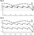
- FIG. 5 an example of use of an electrified vehicle is described in which the user recharges the vehicle's battery daily.
- the invention is particularly suitable for this type of use and makes it possible to limit the target charge level and thus extend the life of its battery.
- the state of charge level of the vehicle's battery is represented, as a percentage of the battery capacity.
- a time axis is represented over a period of one week.
- This user profile travels approximately fifty kilometers daily (D1, D2, D3, D4, D5, D6) and recharges approximately 15% of the battery capacity each time recharge.
- the recharge events are represented by a circle. At the end of the week, it occasionally travels a longer route requiring a 40% recharge.
- the target charge level for each session is set to 100% and varies each day between 100% and 85%, except at the end of the week when the level can reach 60%. Under these assumptions, the average charge level of the battery is approximately 94%.
- the same example of use is described for which the charging management method according to the invention is activated.
- the target state of charge level SOCc calculated according to the method limits the charging to 55% for this use case.
- the charging history HR and the cumulative distribution CDF for this type of user provide for an energy requirement QE1 of 15% to cover at least 50% of the user's uses, and an energy requirement of QE2 of 40% to cover at least 95% of the user's uses.
- the upper curve represents a recharge management without activation of the SOCc target level limitation and the lower curve represents the activation of the process allowing the SOCc target level to be limited, to 55% in this example, in accordance with the user's usage and the vehicle's recharge frequency. This results in a reduction of the average state of charge of the battery, allowing the life of the electrochemical cells to be extended.
- a simplified embodiment of the charging management method is envisaged in which the method comprises recording a quantity of energy recharged during a charging session. This may be the quantity of energy from the last recharge, for example, or from a charging session chosen by the user, for example one of the sessions from a recorded charging history, if applicable.
- the quantity of energy recharged is calculated identically to step 32 of the embodiment described in Figure 4 .
- the method further comprises configuring the target state of charge level based on the amount of recharged energy that has been recorded.
- the configuration, or updating of the SOCc level value may be conditioned on the lapse of a duration, a number of charging sessions or a user request, for example. More specifically, an energy requirement can be calculated from the recorded quantity and an emergency requirement covering a desired minimum distance. Said recorded quantity and the requirement are added together to determine the target charge level SOCc.
- the configuration of the target state of charge level SOCc provides for the configuration of the charging stop function at this target SOCc level. This mode of managing the target state of charge level can be executed automatically or manually by the user. This embodiment avoids the need to calculate a cumulative distribution of the charging history. Recording a charging history is not mandatory. The last recharged quantity may be sufficient for the implementation of this embodiment. During a charging session, charging is stopped when the charge level reaches the target level.
Landscapes
- Engineering & Computer Science (AREA)
- Power Engineering (AREA)
- Transportation (AREA)
- Mechanical Engineering (AREA)
- Life Sciences & Earth Sciences (AREA)
- Sustainable Development (AREA)
- Sustainable Energy (AREA)
- Charge And Discharge Circuits For Batteries Or The Like (AREA)
Claims (10)
- Verfahren zum Verwalten eines Aufladevorgangs einer Traktionsbatterie (7) für ein Elektrofahrzeug (20), umfassend die Bestimmung eines Zielladezustands, der das Beenden des Aufladevorgangs steuert, umfassend die folgenden Schritte aus :- Aufzeichnen (33) einer Menge an nachgeladener Energie (QER) während einer Aufladesitzung,- Die Konfiguration (38) des Zielladezustands ( SOCc ) als Funktion der Menge der nachgeladenen Energie (QER),
dadurch gekennzeichnet , dass es weiterhin die folgenden Schritte umfasst:- Aufzeichnen (33) eines Aufladeverlaufs (HR) anhand der bei jedem Aufladevorgang aufgeladenen Energiemenge (QER),- Bestimmung (35) einer kumulativen Verteilungsfunktion (CDF) der Aufladehistorie (HR),- Die Bestimmung (37) von mindestens einem Wert eines Energiebedarfs (VBE) bei aus der Verteilungsfunktion (CDF),- Einstellen des Zielladezustands ( SOCc ) auf den Wert des Energiebedarf ( VBE),die kumulative Verteilungsfunktion (CDF) ist eine kumulative WahrscheinlichkeitsfunktionModellieren der kumulierten Wahrscheinlichkeit einer nachgeladenen Energiemenge(QER) aus der Nachladehistorie, wobei die Bestimmung des Wertes des Energiebedarfs (VBE) umfasst :- Die Bestimmung (36) einer ersten Energiemenge (QE1), die eine erste Wahrscheinlichkeit (P1) der Verteilungsfunktion (CDF) abdeckt,- Die Bestimmung (36) einer zweiten Energiemenge (QE2) über einen zweite Wahrscheinlichkeit (P2) der Verteilungsfunktion (CDF) größer als die erste Wahrscheinlichkeit (P1),- Die Auswahl (37) des Maximalwertes zwischen der ersten Menge (QE1) addiert zu einer dritten vorgegebenen Menge (QE3) einerseits und der zweiten Menge (QE2) andererseits. - Verfahren nach Anspruch 1, dadurch gekennzeichnet, dass der Wert des Bedarfs Energie (VBE) ist gleich dem Maximalwert ( QEmax ) plus einer vierten vorgegebenen Energiemenge (QE4).
- Verfahren nach Anspruch 1 oder 2, dadurch gekennzeichnet, dass der Zielladezustand ( SOCc ) bei jeder Serie von n aufeinanderfolgenden Ladesitzungen aktualisiert wird, wobei n eine positive ganze Zahl ist.
- Verfahren nach Anspruch 3, dadurch gekennzeichnet, dass es weiterhin umfasst:bei jeder Aktualisierung des Zielladezustands ( SOCc ), Bestimmen eines ersten und eines zweiten Werts des Zielladezustands ( SOCcn , SOCc n+1 ) für eine erste Serie (H Rn) und einer zweiten Reihe (HR n+1 ), der Vergleich des ersten und zweiten Wertes ( SOCc n,SOCc n+1 ), und wenn die Abweichung größer als ein vorgegebener Schwellenwert ist, dasZurücksetzen des Aufladeverlaufs ( HR) durch die zweite Serie, wenn die Lücke kleiner als der genannte Schwellenwert ist, die Hinzufügung der zweiten Serie zum Aufladeverlauf ( HR).
- Verfahren nach Anspruch 1, dadurch gekennzeichnet, dass das Verfahren umfasst zusätzlich zu den folgenden Schritten zur Erfassung der nachgeladenen Energiemenge (QER) :- Wenn die Verbindung des Fahrzeugs (30) mit einer Ladestation (6) erkannt wird, erfolgt die Erfassung (31) des momentanen Ladezustands ( SOCt ) der Batterie (7),- Berechnung (32) der Ladungsabweichung (QER) zwischen dem momentanen Ladezustanddie Aufzeichnung (33) der Aufladehistorie (HR) besteht aus der Aufzeichnung der Anzahl der Vorkommen jedes Lastabweichungswerts (QER) in einer Aufladetabelle.
( SOCt ) und dem Zielladezustand ( SOCc ) des Ladevorgangs, - Verfahren nach Anspruch 5, dadurch gekennzeichnet, dass der Wert des Energiebedarfs (VBE) gleich dem Maximalwert ( QEmax ) plus einer vierten vorgegebenen Energiemenge (QE4) ist.
- Verfahren nach Anspruch 5 oder 6, dadurch gekennzeichnet, dass die Zustandsebene von Zielladung ( SOCc ) wird bei jeder Serie von n aufeinanderfolgenden Ladevorgängen aktualisiert , wobei n eine positive Ganzzahl ist.
- Verfahren nach Anspruch 7, dadurch gekennzeichnet, dass es ferner bei jeder Aktualisierung des Zielladezustandsniveaus ( SOCc ) die Bestimmung eines ersten und eines zweiten Werts des Zielladezustandsniveaus ( SOCc n, SOCc n+1 ) für eine erste Reihe ( HRn ) und eine zweite Reihe (HR n+1 ) , Vergleichen des ersten und des zweiten Werts ( SOCc n, SOCc n+1 ), und wenn die Abweichung größer als ein vorgegebener Schwellenwert ist, Zurücksetzen des Aufladeverlaufs (HR) durch die zweite Reihe, und wenn die Abweichung kleiner als dieser Schwellenwert ist, Hinzufügen der zweiten Reihe zum Aufladeverlauf (HR).
- Verfahren nach einem der Ansprüche 1 bis 8 , dadurch gekennzeichnet, dass es umfasst ferner den Vorgang eines elektrischen Aufladens der Batterie (7) des Fahrzeugs (20) und die Steuerung des Stoppens des Aufladens, wenn der momentane Ladezustand ( SOCt ) den Zielladezustandspegel ( SOCc ) erreicht.
- Elektrifiziertes Kraftfahrzeug (20) mit einem Traktionsbatteriesystem (7) und eine Vorrichtung (1) zur Verwaltung eines Aufladevorgangs des Batteriesystems (7), dadurch gekennzeichnet, dass das Gerät (1) so konfiguriert ist, dass es das Verfahren zum Verwalten eines Ladevorgangs gemäß einem der Ansprüche 1 bis 9 umsetzt.
Applications Claiming Priority (2)
| Application Number | Priority Date | Filing Date | Title |
|---|---|---|---|
| FR2108940A FR3126560A1 (fr) | 2021-08-26 | 2021-08-26 | Procede de gestion d’une session de recharge d’un vehicule electrifie pour determiner un etat de charge cible en fin de charge |
| PCT/FR2022/051138 WO2023025995A1 (fr) | 2021-08-26 | 2022-06-14 | Procede de gestion d'une session de recharge d'un vehicule electrifie pour determiner un etat de charge cible en fin de charge |
Publications (2)
| Publication Number | Publication Date |
|---|---|
| EP4393043A1 EP4393043A1 (de) | 2024-07-03 |
| EP4393043B1 true EP4393043B1 (de) | 2025-05-07 |
Family
ID=78212247
Family Applications (1)
| Application Number | Title | Priority Date | Filing Date |
|---|---|---|---|
| EP22741338.2A Active EP4393043B1 (de) | 2021-08-26 | 2022-06-14 | Verfahren zur verwaltung eines ladevorgangs eines elektrifizierten fahrzeugs zur bestimmung eines zielladezustands am ende des ladevorgangs |
Country Status (4)
| Country | Link |
|---|---|
| EP (1) | EP4393043B1 (de) |
| CN (1) | CN117897878A (de) |
| FR (1) | FR3126560A1 (de) |
| WO (1) | WO2023025995A1 (de) |
Families Citing this family (1)
| Publication number | Priority date | Publication date | Assignee | Title |
|---|---|---|---|---|
| FR3162862A1 (fr) * | 2024-06-03 | 2025-12-05 | Stellantis Auto Sas | Estimation de la durée de recharge d’une batterie d’un véhicule par une borne de recharge |
Family Cites Families (10)
| Publication number | Priority date | Publication date | Assignee | Title |
|---|---|---|---|---|
| FR2108940A2 (en) | 1969-11-14 | 1972-05-26 | Rhodiaceta | Synthetic polymeric pulp - soil improver for growth of seed vegetables |
| FR2952235B1 (fr) | 2009-10-29 | 2015-01-16 | Commissariat Energie Atomique | Procede de charge ou de decharge d'une batterie pour determiner la fin de charge ou de decharge en fonction de mesures de courant et de temperature |
| JP5975376B2 (ja) | 2011-02-24 | 2016-08-23 | パナソニックIpマネジメント株式会社 | 充電制御装置及び充電制御用のプログラム |
| US9751424B2 (en) * | 2011-07-14 | 2017-09-05 | Ford Global Technologies, Llc | Method and system for determining a target state of charge to charge a battery in a vehicle using external electric power |
| US9013143B2 (en) * | 2012-03-09 | 2015-04-21 | GM Global Technology Operations LLC | Method for charging a plug-in electric vehicle |
| US9306412B2 (en) * | 2012-03-30 | 2016-04-05 | Toyota Jidosha Kabushiki Kaisha | Optimum charging for electric-based vehicle |
| US10099569B2 (en) * | 2016-09-29 | 2018-10-16 | GM Global Technology Operations LLC | Adaptive system and method for optimizing a fleet of plug-in vehicles |
| DE102019003823A1 (de) * | 2019-05-31 | 2020-12-03 | Daimler Ag | Batteriemanagementsystem und Betrieb eines Energiespeichers für elektrische Energie |
| US11498452B2 (en) * | 2019-11-11 | 2022-11-15 | Ford Global Technologies, Llc | Vehicle charging control systems and methods |
| US11417916B2 (en) * | 2020-01-13 | 2022-08-16 | Ford Global Technologies, Llc | Intelligent vehicle battery charging for high capacity batteries |
-
2021
- 2021-08-26 FR FR2108940A patent/FR3126560A1/fr not_active Withdrawn
-
2022
- 2022-06-14 WO PCT/FR2022/051138 patent/WO2023025995A1/fr not_active Ceased
- 2022-06-14 EP EP22741338.2A patent/EP4393043B1/de active Active
- 2022-06-14 CN CN202280058067.3A patent/CN117897878A/zh active Pending
Also Published As
| Publication number | Publication date |
|---|---|
| FR3126560A1 (fr) | 2023-03-03 |
| EP4393043A1 (de) | 2024-07-03 |
| CN117897878A (zh) | 2024-04-16 |
| WO2023025995A1 (fr) | 2023-03-02 |
Similar Documents
| Publication | Publication Date | Title |
|---|---|---|
| EP3944982B1 (de) | Gemeinsames mehrpunkt-ladesystem für elektrofahrzeuge | |
| EP2803523B1 (de) | Dynamisches und vorausschauendes Verwaltungsverfahren der elektrischen Aufladung von Batterien | |
| EP4093633B1 (de) | Verfahren und vorrichtung zur steuerung eines energiespeichersystems, beispielsweise eine fahrzeugbatterie | |
| EP4288304B1 (de) | Verfahren zur schätzung eines ladezustands einer batterie eines elektrofahrzeugs für fernüberwachungssystem | |
| WO2020114795A1 (fr) | Procédé de gestion optimisée de la charge d'une flotte de véhicules électriques | |
| JP7444871B2 (ja) | 充電端末によってアキュムレータバッテリーを充電するための方法 | |
| FR3122951A1 (fr) | Procédé et système de contrôle de la recharge d’une flotte de véhicules automobiles électriques | |
| EP4393043B1 (de) | Verfahren zur verwaltung eines ladevorgangs eines elektrifizierten fahrzeugs zur bestimmung eines zielladezustands am ende des ladevorgangs | |
| EP2892753A2 (de) | Wiederaufladung einer gruppe von batterien | |
| EP2928721B1 (de) | Verfahren zur verteilten verwaltung des ladevorgangs von traktionsbatterien von elektrofahrzeugen | |
| WO2020089543A1 (fr) | Dispositif de recharge rapide de vehicules electriques via des vehicules electriques de location | |
| FR3002377A1 (fr) | Procede d'optimisation de l'energie de recharge et de la duree de vie de batteries electriques | |
| EP4157665B1 (de) | Verfahren zur abschätzung des ladezustands einer batterie insbesondere zur wiederaufladensverwaltung von elektrofahrzeugen | |
| FR3140711A1 (fr) | Procédé d’estimation d’une durée de charge restant pour un véhicule automobile électrifié | |
| FR3091788A1 (fr) | Méthode de charge d’une batterie d’accumulateurs par une borne de charge | |
| WO2023110596A1 (fr) | Système de gestion d'une batterie et procédé d'équilibrage des charges des accumulateurs de la batterie | |
| FR3161495A1 (fr) | Obtention d’informations relatives à des caractéristiques d’une borne de recharge | |
| FR2997349A1 (fr) | Systeme et procede de gestion de l'approvisionnement en energie d'un vehicule a partir d'une source exterieure d'energie | |
| FR3156711A1 (fr) | Procede de controle d’une recharge d’une batterie d’un vehicule | |
| FR3102859A1 (fr) | Méthode de charge d’une batterie d’accumulateurs par une borne de charge | |
| FR3155756A1 (fr) | Systeme de gestion d’energie de batiment et de vehicule automobile, procede et programme sur la base d’un tel systeme |
Legal Events
| Date | Code | Title | Description |
|---|---|---|---|
| STAA | Information on the status of an ep patent application or granted ep patent |
Free format text: STATUS: UNKNOWN |
|
| STAA | Information on the status of an ep patent application or granted ep patent |
Free format text: STATUS: THE INTERNATIONAL PUBLICATION HAS BEEN MADE |
|
| PUAI | Public reference made under article 153(3) epc to a published international application that has entered the european phase |
Free format text: ORIGINAL CODE: 0009012 |
|
| STAA | Information on the status of an ep patent application or granted ep patent |
Free format text: STATUS: REQUEST FOR EXAMINATION WAS MADE |
|
| 17P | Request for examination filed |
Effective date: 20240115 |
|
| AK | Designated contracting states |
Kind code of ref document: A1 Designated state(s): AL AT BE BG CH CY CZ DE DK EE ES FI FR GB GR HR HU IE IS IT LI LT LU LV MC MK MT NL NO PL PT RO RS SE SI SK SM TR |
|
| DAV | Request for validation of the european patent (deleted) | ||
| DAX | Request for extension of the european patent (deleted) | ||
| RIC1 | Information provided on ipc code assigned before grant |
Ipc: B60L 58/16 20190101ALI20241210BHEP Ipc: B60L 58/15 20190101ALI20241210BHEP Ipc: B60L 58/13 20190101ALI20241210BHEP Ipc: B60L 53/60 20190101ALI20241210BHEP Ipc: H02J 7/00 20060101AFI20241210BHEP |
|
| GRAP | Despatch of communication of intention to grant a patent |
Free format text: ORIGINAL CODE: EPIDOSNIGR1 |
|
| STAA | Information on the status of an ep patent application or granted ep patent |
Free format text: STATUS: GRANT OF PATENT IS INTENDED |
|
| INTG | Intention to grant announced |
Effective date: 20250130 |
|
| GRAS | Grant fee paid |
Free format text: ORIGINAL CODE: EPIDOSNIGR3 |
|
| GRAA | (expected) grant |
Free format text: ORIGINAL CODE: 0009210 |
|
| STAA | Information on the status of an ep patent application or granted ep patent |
Free format text: STATUS: THE PATENT HAS BEEN GRANTED |
|
| AK | Designated contracting states |
Kind code of ref document: B1 Designated state(s): AL AT BE BG CH CY CZ DE DK EE ES FI FR GB GR HR HU IE IS IT LI LT LU LV MC MK MT NL NO PL PT RO RS SE SI SK SM TR |
|
| REG | Reference to a national code |
Ref country code: GB Ref legal event code: FG4D Free format text: NOT ENGLISH |
|
| REG | Reference to a national code |
Ref country code: CH Ref legal event code: EP |
|
| REG | Reference to a national code |
Ref country code: DE Ref legal event code: R096 Ref document number: 602022014386 Country of ref document: DE |
|
| REG | Reference to a national code |
Ref country code: IE Ref legal event code: FG4D Free format text: LANGUAGE OF EP DOCUMENT: FRENCH |
|
| REG | Reference to a national code |
Ref country code: DE Ref legal event code: R084 Ref document number: 602022014386 Country of ref document: DE |
|
| PGFP | Annual fee paid to national office [announced via postgrant information from national office to epo] |
Ref country code: DE Payment date: 20250520 Year of fee payment: 4 |
|
| PGFP | Annual fee paid to national office [announced via postgrant information from national office to epo] |
Ref country code: FR Payment date: 20250619 Year of fee payment: 4 |
|
| PGFP | Annual fee paid to national office [announced via postgrant information from national office to epo] |
Ref country code: AT Payment date: 20250721 Year of fee payment: 4 |
|
| REG | Reference to a national code |
Ref country code: NL Ref legal event code: MP Effective date: 20250507 |
|
| PG25 | Lapsed in a contracting state [announced via postgrant information from national office to epo] |
Ref country code: PT Free format text: LAPSE BECAUSE OF FAILURE TO SUBMIT A TRANSLATION OF THE DESCRIPTION OR TO PAY THE FEE WITHIN THE PRESCRIBED TIME-LIMIT Effective date: 20250908 Ref country code: ES Free format text: LAPSE BECAUSE OF FAILURE TO SUBMIT A TRANSLATION OF THE DESCRIPTION OR TO PAY THE FEE WITHIN THE PRESCRIBED TIME-LIMIT Effective date: 20250507 Ref country code: FI Free format text: LAPSE BECAUSE OF FAILURE TO SUBMIT A TRANSLATION OF THE DESCRIPTION OR TO PAY THE FEE WITHIN THE PRESCRIBED TIME-LIMIT Effective date: 20250507 |
|
| REG | Reference to a national code |
Ref country code: LT Ref legal event code: MG9D |
|
| PG25 | Lapsed in a contracting state [announced via postgrant information from national office to epo] |
Ref country code: NO Free format text: LAPSE BECAUSE OF FAILURE TO SUBMIT A TRANSLATION OF THE DESCRIPTION OR TO PAY THE FEE WITHIN THE PRESCRIBED TIME-LIMIT Effective date: 20250807 Ref country code: GR Free format text: LAPSE BECAUSE OF FAILURE TO SUBMIT A TRANSLATION OF THE DESCRIPTION OR TO PAY THE FEE WITHIN THE PRESCRIBED TIME-LIMIT Effective date: 20250808 |
|
| PG25 | Lapsed in a contracting state [announced via postgrant information from national office to epo] |
Ref country code: PL Free format text: LAPSE BECAUSE OF FAILURE TO SUBMIT A TRANSLATION OF THE DESCRIPTION OR TO PAY THE FEE WITHIN THE PRESCRIBED TIME-LIMIT Effective date: 20250507 Ref country code: NL Free format text: LAPSE BECAUSE OF FAILURE TO SUBMIT A TRANSLATION OF THE DESCRIPTION OR TO PAY THE FEE WITHIN THE PRESCRIBED TIME-LIMIT Effective date: 20250507 |
|
| REG | Reference to a national code |
Ref country code: AT Ref legal event code: MK05 Ref document number: 1793594 Country of ref document: AT Kind code of ref document: T Effective date: 20250507 |
|
| PG25 | Lapsed in a contracting state [announced via postgrant information from national office to epo] |
Ref country code: BG Free format text: LAPSE BECAUSE OF FAILURE TO SUBMIT A TRANSLATION OF THE DESCRIPTION OR TO PAY THE FEE WITHIN THE PRESCRIBED TIME-LIMIT Effective date: 20250507 |
|
| PG25 | Lapsed in a contracting state [announced via postgrant information from national office to epo] |
Ref country code: AT Free format text: LAPSE BECAUSE OF FAILURE TO SUBMIT A TRANSLATION OF THE DESCRIPTION OR TO PAY THE FEE WITHIN THE PRESCRIBED TIME-LIMIT Effective date: 20250507 Ref country code: HR Free format text: LAPSE BECAUSE OF FAILURE TO SUBMIT A TRANSLATION OF THE DESCRIPTION OR TO PAY THE FEE WITHIN THE PRESCRIBED TIME-LIMIT Effective date: 20250507 |
|
| PG25 | Lapsed in a contracting state [announced via postgrant information from national office to epo] |
Ref country code: RS Free format text: LAPSE BECAUSE OF FAILURE TO SUBMIT A TRANSLATION OF THE DESCRIPTION OR TO PAY THE FEE WITHIN THE PRESCRIBED TIME-LIMIT Effective date: 20250807 |
|
| PG25 | Lapsed in a contracting state [announced via postgrant information from national office to epo] |
Ref country code: IS Free format text: LAPSE BECAUSE OF FAILURE TO SUBMIT A TRANSLATION OF THE DESCRIPTION OR TO PAY THE FEE WITHIN THE PRESCRIBED TIME-LIMIT Effective date: 20250907 |
|
| PG25 | Lapsed in a contracting state [announced via postgrant information from national office to epo] |
Ref country code: LV Free format text: LAPSE BECAUSE OF FAILURE TO SUBMIT A TRANSLATION OF THE DESCRIPTION OR TO PAY THE FEE WITHIN THE PRESCRIBED TIME-LIMIT Effective date: 20250507 |
|
| PG25 | Lapsed in a contracting state [announced via postgrant information from national office to epo] |
Ref country code: DK Free format text: LAPSE BECAUSE OF FAILURE TO SUBMIT A TRANSLATION OF THE DESCRIPTION OR TO PAY THE FEE WITHIN THE PRESCRIBED TIME-LIMIT Effective date: 20250507 Ref country code: SM Free format text: LAPSE BECAUSE OF FAILURE TO SUBMIT A TRANSLATION OF THE DESCRIPTION OR TO PAY THE FEE WITHIN THE PRESCRIBED TIME-LIMIT Effective date: 20250507 |
|
| PG25 | Lapsed in a contracting state [announced via postgrant information from national office to epo] |
Ref country code: CZ Free format text: LAPSE BECAUSE OF FAILURE TO SUBMIT A TRANSLATION OF THE DESCRIPTION OR TO PAY THE FEE WITHIN THE PRESCRIBED TIME-LIMIT Effective date: 20250507 |
|
| PG25 | Lapsed in a contracting state [announced via postgrant information from national office to epo] |
Ref country code: EE Free format text: LAPSE BECAUSE OF FAILURE TO SUBMIT A TRANSLATION OF THE DESCRIPTION OR TO PAY THE FEE WITHIN THE PRESCRIBED TIME-LIMIT Effective date: 20250507 |
|
| PG25 | Lapsed in a contracting state [announced via postgrant information from national office to epo] |
Ref country code: SK Free format text: LAPSE BECAUSE OF FAILURE TO SUBMIT A TRANSLATION OF THE DESCRIPTION OR TO PAY THE FEE WITHIN THE PRESCRIBED TIME-LIMIT Effective date: 20250507 |
|
| REG | Reference to a national code |
Ref country code: CH Ref legal event code: H13 Free format text: ST27 STATUS EVENT CODE: U-0-0-H10-H13 (AS PROVIDED BY THE NATIONAL OFFICE) Effective date: 20260127 |
|
| PG25 | Lapsed in a contracting state [announced via postgrant information from national office to epo] |
Ref country code: IT Free format text: LAPSE BECAUSE OF FAILURE TO SUBMIT A TRANSLATION OF THE DESCRIPTION OR TO PAY THE FEE WITHIN THE PRESCRIBED TIME-LIMIT Effective date: 20250507 |
|
| REG | Reference to a national code |
Ref country code: DE Ref legal event code: R097 Ref document number: 602022014386 Country of ref document: DE |
|
| PG25 | Lapsed in a contracting state [announced via postgrant information from national office to epo] |
Ref country code: LU Free format text: LAPSE BECAUSE OF NON-PAYMENT OF DUE FEES Effective date: 20250614 |
|
| PG25 | Lapsed in a contracting state [announced via postgrant information from national office to epo] |
Ref country code: MC Free format text: LAPSE BECAUSE OF FAILURE TO SUBMIT A TRANSLATION OF THE DESCRIPTION OR TO PAY THE FEE WITHIN THE PRESCRIBED TIME-LIMIT Effective date: 20250507 |
|
| REG | Reference to a national code |
Ref country code: BE Ref legal event code: MM Effective date: 20250630 |
|
| PG25 | Lapsed in a contracting state [announced via postgrant information from national office to epo] |
Ref country code: RO Free format text: LAPSE BECAUSE OF FAILURE TO SUBMIT A TRANSLATION OF THE DESCRIPTION OR TO PAY THE FEE WITHIN THE PRESCRIBED TIME-LIMIT Effective date: 20250507 |
|
| PLBE | No opposition filed within time limit |
Free format text: ORIGINAL CODE: 0009261 |
|
| STAA | Information on the status of an ep patent application or granted ep patent |
Free format text: STATUS: NO OPPOSITION FILED WITHIN TIME LIMIT |
|
| REG | Reference to a national code |
Ref country code: CH Ref legal event code: L10 Free format text: ST27 STATUS EVENT CODE: U-0-0-L10-L00 (AS PROVIDED BY THE NATIONAL OFFICE) Effective date: 20260318 |
|
| PG25 | Lapsed in a contracting state [announced via postgrant information from national office to epo] |
Ref country code: IE Free format text: LAPSE BECAUSE OF NON-PAYMENT OF DUE FEES Effective date: 20250614 |
|
| 26N | No opposition filed |
Effective date: 20260210 |
|
| PG25 | Lapsed in a contracting state [announced via postgrant information from national office to epo] |
Ref country code: BE Free format text: LAPSE BECAUSE OF NON-PAYMENT OF DUE FEES Effective date: 20250630 |
|
| PG25 | Lapsed in a contracting state [announced via postgrant information from national office to epo] |
Ref country code: CH Free format text: LAPSE BECAUSE OF NON-PAYMENT OF DUE FEES Effective date: 20250630 |