EP4393285A1 - Machine de travail - Google Patents
Machine de travail Download PDFInfo
- Publication number
- EP4393285A1 EP4393285A1 EP22861360.0A EP22861360A EP4393285A1 EP 4393285 A1 EP4393285 A1 EP 4393285A1 EP 22861360 A EP22861360 A EP 22861360A EP 4393285 A1 EP4393285 A1 EP 4393285A1
- Authority
- EP
- European Patent Office
- Prior art keywords
- work
- working
- route
- acquirer
- portions
- Prior art date
- Legal status (The legal status is an assumption and is not a legal conclusion. Google has not performed a legal analysis and makes no representation as to the accuracy of the status listed.)
- Pending
Links
Images














Classifications
-
- A—HUMAN NECESSITIES
- A01—AGRICULTURE; FORESTRY; ANIMAL HUSBANDRY; HUNTING; TRAPPING; FISHING
- A01B—SOIL WORKING IN AGRICULTURE OR FORESTRY; PARTS, DETAILS, OR ACCESSORIES OF AGRICULTURAL MACHINES OR IMPLEMENTS, IN GENERAL
- A01B69/00—Steering of agricultural machines or implements; Guiding agricultural machines or implements on a desired track
- A01B69/007—Steering or guiding of agricultural vehicles, e.g. steering of the tractor to keep the plough in the furrow
- A01B69/008—Steering or guiding of agricultural vehicles, e.g. steering of the tractor to keep the plough in the furrow automatic
-
- A—HUMAN NECESSITIES
- A01—AGRICULTURE; FORESTRY; ANIMAL HUSBANDRY; HUNTING; TRAPPING; FISHING
- A01B—SOIL WORKING IN AGRICULTURE OR FORESTRY; PARTS, DETAILS, OR ACCESSORIES OF AGRICULTURAL MACHINES OR IMPLEMENTS, IN GENERAL
- A01B79/00—Methods for working soil
- A01B79/005—Precision agriculture
Definitions
- the present invention relates to a working machine such as a tractor.
- a working vehicle assistance system of Patent Literature 1 includes a vehicle position detector that detects a position of a working vehicle, an unfinished region external shape map calculator that calculates an external shape map of an unfinished region within a planned work region from vehicle position data that is acquired by the vehicle position detector when the working vehicle travels along an outer periphery of the planned work region while doing work, and a path calculator that calculates a target travelling path along which the working vehicle travels while doing work in the unfinished region based on the external shape map calculated by the unfinished region external shape map calculator.
- the first work acquirer may acquire a first working width of the first working device as the first information.
- the second work acquirer may acquire a second working width of the second working device as the second information.
- the route creator may create the first portions by shifting the plurality of second portions based on a difference between the first working width acquired by the first work acquirer and the second working width acquired by the second work acquirer.
- the route creator may create the first portions by shifting the plurality of second portions by a product of (i) the difference between the first working width acquired by the first work acquirer and the second working width acquired by the second work acquirer and (ii) a natural number multiple of 1/2.
- the first work acquirer may acquire a first working width of the first working device as the first information.
- the route creator may create the second route based on the first working width.
- the route acquirer may acquire the second route created by the route creator.
- the working machine may further include a position detector to detect a position of the vehicle body.
- the route acquirer may acquire the second route based on one or more positions of the vehicle body acquired by the position detector when the vehicle body having the second working device connected thereto moves.
- the working machine may further include a position detector to detect a position of the vehicle body, and a display to display the position of the vehicle body detected by the position detector and the first route created by the route creator.
- the working machine may further include a position detector to detect a position of the vehicle body, and an auto-steering controller to control steering of the traveling device based on the position of the vehicle body detected by the position detector and the first route created by the route creator.
- the working machine may further include a position detector to detect a position of the vehicle body, and an automatic travel controller to control steering and a vehicle speed of the traveling device based on the position of the vehicle body detected by the position detector and the first route created by the route creator.
- the working machine may further include a linkage to selectively connect the first working device or the second working device to the vehicle body.
- the first route may be a path traveled by the vehicle body having the first working device attached thereto via the linkage.
- the second route may be a path traveled by the vehicle body having the second working device attached thereto via the linkage.
- the front wheels 4A are connected by an arm (knuckle arm) 5 that changes a direction of the front wheels 4A.
- the knuckle arm 5 changes the direction of the front wheels 4A, thereby allowing the vehicle body 2 to travel straight and turn. Note that it is only necessary that the vehicle body 2 can travel straight and turn.
- a rotational speed of the front wheel 4A and the rear wheel 4B on the one side (left side) and a rotational speed of the front wheel 4A and the rear wheel 4B on the other side (right side) may be changed to achieve the straight traveling and turning.
- the front wheels 4A and the rear wheels 4B may be tires or may be crawlers.
- the vehicle body 2 is provided with a PTO shaft 6 that outputs power of the prime mover 8 to an outside and the operator's seat 7 on which the operator sits.
- the working device 60 is a device attachable to the vehicle body 2. In a case where the working machine 1 is a tractor, the working device 60 is coupled to the vehicle body 2 with the use of the linkage 30.
- the working device 60 may operate upon receipt of power input from an outside, for example, power input from the PTO shaft 6.
- the working device 60 may include hydraulic equipment (not illustrated) that is driven by hydraulic fluid delivered by the first hydraulic pump 9, and the hydraulic equipment may cause the working device 60 to operate.
- the working device 60 is a cultivator 90 for cultivation, a ridge maker 71 for ridge making, a fertilizer spreader for spreading a fertilizer, an agricultural chemical spreader 85 for spreading an agricultural chemical for pest control, a seed spreader 75 for seeding, a transplanter for transplanting a crop (seedling), a harvester for harvesting crops, a mower for mowing pasture grass or the like, a tedder for spreading pasture grass or the like, a rake for gathering pasture grass or the like, a baler for baling pasture grass or the like, or the like. That is, the linkage 30 can couple the working device 60 selected from among the various kinds described above to the vehicle body 2.
- the sub-transmission unit 11c includes a plurality of gears and a shifter that changes connection of the gears.
- the sub-transmission unit 11c changes rotation input from the main transmission unit 11b and outputs the changed rotation (change speed stages) by changing connection (engagement) of the plurality of gears as appropriate by the shifter.
- the front transmission unit 11f includes a first clutch 16A and a second clutch 16B.
- power from the propeller shaft 11a can be transmitted, for example, power of the shuttle shaft 12 is transmitted via a gear and a transmission shaft.
- Power from the first clutch 16A and the second clutch 16B can be transmitted to a front axle 18F via a front transmission shaft 19.
- the front transmission shaft 19 is connected to a front wheel differential 17F, and the front wheel differential 17F rotatably supports the front axle 18F to which the front wheels 4A are attached.
- the first clutch 16A and the second clutch 16B are hydraulic clutches or the like.
- a fluid passage is connected to the first clutch 16A, and the fluid passage is connected to a first actuation valve 25a to which a hydraulic fluid delivered from the first hydraulic pump 9 is supplied.
- the first clutch 16A is switched between a connected state and a cutoff state depending on an opening of the first actuation valve 25a.
- a fluid passage is connected to the second clutch 16B, and the fluid passage is connected to a second actuation valve 25b.
- the second clutch 16B is switched between a connected state and a cutoff state depending on an opening of the second actuation valve 25b.
- the first actuation valve 25a and the second actuation valve 25b are, for example, two-position switching valves equipped with a solenoid valve and are switched to a connected state or a cutoff state by energizing or deenergizing a solenoid of the solenoid valve.
- a state (4WD increased-speed state) is created in which four-wheel drive is performed and the rotational speed of the front wheels 4A is higher than the rotational speed of the rear wheels 4B.
- power of the shuttle shaft 12 is not transmitted to the front wheels 4A. This creates a two-wheel-drive (2WD) state in which the rear wheels 4B are driven by power.
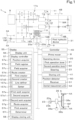
- the working machine 1 includes a controller 40 and a storing unit (memory and/or storage) 41.
- the controller 40 is a device realized by an electric/electronic circuit, a program stored in a CPU or the like, and the like.
- the controller 40 controls various devices of the working machine 1. Specifically, the controller 40 can perform control such as control of the first hydraulic device 31, the working device 60, and change of output of the first hydraulic pump 9.
- the storing unit 41 is a non-volatile memory or the like and stores therein, for example, various kinds of information concerning control of the controller 40.
- the working machine 1 includes a position detector (positioning device) 50.
- the position detector 50 can detect a position thereof (measured position information including latitude and longitude) by a satellite positioning system (positioning satellite) such as D-GPS, GPS, GLONASS, BeiDou, Galileo, or Michibiki. That is, the position detector 50 receives a satellite signal (a position of the positioning satellite, a transmission time, correction information, and the like) transmitted from the positioning satellite and detects a position (e.g., latitude and longitude) of the working machine 1, that is, a vehicle body position VP based on the satellite signal.
- the position detector 50 includes a receiver 51 and an inertial measurement unit (IMU) 52.
- IMU inertial measurement unit
- the receiver 51 is a device that includes an antenna and the like and receives a satellite signal transmitted from the positioning satellite, and is attached to the working machine 1 separately from the inertial measurement unit 52.
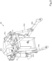
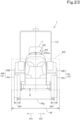
- the receiver 51 is attached to an upper portion of a ROPS 10 provided on the vehicle body 2, as illustrated in FIGS. 22 and 23 .
- an attachment position of the receiver 51 is not limited to the above position, and may be a central portion of a hood or, in a case where the vehicle body 2 is provided with a protection mechanism such as a cabin, may be an upper portion of the protection mechanism.
- the working machine 1 includes a display 55.
- the display 55 is, for example, a traveling assistance device provided in the vicinity of the operator's seat 7.
- the display 55 includes a display unit 56, a display controller 57, and a display storing unit (memory and/or storage) 58.
- the display unit 56 is a liquid crystal panel, a touch panel, or another kind of panel and can display information for assisting traveling of the working machine 1 such as a field F expressing an agricultural field G.
- the display unit 56 can display various kinds of information concerning the working machine 1 and the working device 60 in addition to the information for assisting traveling of the working machine 1.
- the display controller 57 is realized by an electric/electronic component provided in the display 55, a program stored in the display storing unit 58, which will be described later, and the like.
- the display controller 57 causes a screen visualizing information stored in the display storing unit 58 to be displayed on the display unit 56.
- the display controller 57 of the display 55 also functions as the position acquirer 57a, the field register 57b, and the field acquirer 57c in the present embodiment, the controller 40 or the like may include the position acquirer 57a, the field register 57b, and the field acquirer 57c, and the configuration thereof is not limited to the above configuration.
- a storing unit such as a memory in which positional information of a plurality of position measurement points is stored in advance and the display 55 are connected and the positional information of the plurality of position measurement points is acquired from the storing unit.
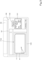
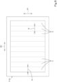
- the display controller 57 causes the field registration screen D1 to be displayed on the display unit 56.
- the display unit 56 displays the field registration screen D1
- the operator causes the working machine 1 to circle within the agricultural field G by operating the working machine 1.
- the position acquirer 57a acquires the vehicle body position VP detected by the position detector 50 on a predetermined cycle, and records the vehicle body position VP in the display storing unit 58 each time and causes the vehicle body position VP to be displayed on the field display portion 100 each time (only some vehicle body positions VP are displayed in FIG. 3 for convenience of description).
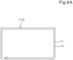
- the field register 57b calculates a traveling track T1 of the working machine 1 based on the recorded vehicle body positions VP.
- the display controller 57 causes the traveling track T1 to be displayed on the field F in the field display portion 100, as illustrated in FIG. 4A .
- a line T1 passing the plurality of vehicle body positions VP in an order of detection (order of acquisition) and returning to an initially detected position VP is obtained as the traveling track of the working machine 1.
- the vehicle body position VP is a GPS position of the position detector 50
- the traveling track T1 is a track of movement of the GPS position.
- the field register 57b forms a line H1 between the traveling track T1 and an external shape line of the field F by shifting the traveling track T1 outward by an amount equivalent to an interval in the width direction from the GPS position of the working machine 1 to an outer end of the circling working device 60 (in FIG. 4A , a left end of the working device 60 since the working machine 1 circles in the agricultural field G in a clockwise direction).
- the shift amount is set identical to a half of an external width (a length in the width direction) of the working device 60 or a half of a working width W (a length in the width direction of a range where the working device 60 exerts some kind of action on the agricultural field G) of the working device 60 since the GPS position of the position detector 50 is located at a center of the working machine 1 and the center of the working machine 1 in the width direction and a center of the working device 60 in the width direction match.
- the line H1 may be formed between the traveling track T1 and the external shape line of the field F while setting, as the shift amount, a value that is smaller by a predetermined degree or larger by a predetermined degree than the interval in the width direction from the GPS position of the working machine 1 to the outer end of the circling working device 60.
- the field register 57b regards the line H1 thus formed as a contour (external shape) of the agricultural field G and registers (stores) the field F expressed by the contour H1 in the display storing unit 58.
- the field register 57b associates agricultural field identification information such as a name of the agricultural field G (agricultural field name) and an agricultural field management number with the field F.
- a plurality of fields F and the like can be registered in the display storing unit 58, and when the field register 57b registers a field F, the display controller 57 causes this field F (the contour H1 of the agricultural field G) to be displayed.
- the type I device 61 includes a plurality of working units 61a
- the plurality of working units 61a are arranged at equal intervals (at first interval(s) x) in the width direction.
- the first interval x is fixed in advance for some type I devices 61.
- the first interval x may be freely selected by an operator in accordance with a series of work done in the agricultural field G. In such a case, the first interval x is selected such that an interval between the working units 61a of one working device 60 and an interval between the working units 61a of another working device 60 are the same.
- Each work line R1 is a ridge or an upper surface of a ridge which may be damaged or crops which may be damaged if contacted by the traveling device 4.
- the work lines R1 are non-travelable lines R1 where the traveling device 4 cannot travel. That is, the non-travelable lines R1 are lines that extend from one of opposite edges to the other of the agricultural field G (in the first direction B 1) and are formed at first interval(s) x in the second direction B2.
- the non-travelable lines R1 are substantially straight in the present embodiment, the non-travelable lines R1 may be relatively gently curved or may have a zigzag shape. For convenience of description, the following mainly discusses a case where the work lines R1 are ridges or crops.
- the position of the traveling device 4 (the positions of the first traveling unit 4L and the second traveling unit 4R), the first interval x, and the unit working width Wc is described below.
- the dimension (third width) Wf of a ground contact surface of the traveling device 4 in the width direction and the tread (fourth width) Wg are set such that, in a case where the first traveling unit 4L is located in one line R2, the second traveling unit 4R is located in another line R2.
- the lines R2 are travelable lines R2 set such that the first traveling unit 4L and the second traveling unit 4R do not make contact with at least the upper surfaces of the ridges although the first traveling unit 4L and the second traveling unit 4R may damage skirts of the ridges, as long as the first traveling unit 4L and the second traveling unit 4R travel along the lines R2 when the traveling device 4 travels.
- the ridge maker 71 illustrated in FIG. 9A includes a rotary cultivator 73 located forward of the ridgers 72, and the ridgers 72 make ridges by shaping the soil thrown backward by the rotary cultivator 73.
- the rotary cultivator 73 includes a tine shaft 73a and tillage tines 73b.
- the tine shaft 73a includes a rotary axis extending in the width direction and performs tillage by being driven by power output from the PTO shaft 6.
- the seed spreader 75 includes containers 78 in which seeds are contained, hoses (not illustrated) that connect the containers 78 and the seeding nozzles 76, and feeders 79 that feed seeds from the containers 78 through the hoses. Accordingly, seeds fed to the hoses by driving the feeders 79 are sown onto the agricultural field G from the seeding nozzles 76 through the hoses, and the compacting rollers 77 compact at least the portions where the seeds are sown. Since the seed spreader 75 includes the four seeding nozzles 76 and the four compacting rollers 77 in the example illustrated in FIG. 9B , the seed spreader 75 can make four crop lines Rb by being towed by the working machine 1.
- the type II device 62 is described below based on the agricultural chemical spreader 85 illustrated in FIG. 9C as an example.
- the agricultural chemical spreader 85 includes a plurality of agricultural chemical nozzles 86 as the working body 62a, and the plurality of agricultural chemical nozzles 86 are arranged in the width direction.
- the plurality of agricultural chemical nozzles 86 are arranged at interval(s) equal to or different from the first intervals x, and perform spreading in a relatively large range without forming a region where work is done (work line R1) and a region where work is not done in the entire unit work section E irrespective of the positions of ridges or crops.
- the type III device 63 is the working device 60 that directly interferes with soil irrespective of the presence or absence of ridges or crop lines, such as the cultivator 90. As illustrated in FIG. 8C , the type III device 63 includes a single working body 63a, as with the type II device 62, unlike the type I device 61.
- the working body 63a is a structure that does ground work on the agricultural field G and forms a work region R4 extending in the traveling direction of the working machine 1 when the type II device 62 is towed by the working machine 1. It is noted here that the working width W of the type III device 63 and the dimension of the work region R4 in the width direction are the same, and the work region R3 and the unit work section E match.
- second work Jn-1 work done before the first work Jn
- second working device 60B working device 60B.
- the first work Jn, the second work Jn-1, and the others are described based on an example case where potato is grown in the agricultural field G.
- a series of work for growing potato is done in the order of fertilization J1, harrowing J2, pest control J3, ridge making J4, plating J5, weedkilling J6, ridging J7, disbudding J8, additional fertilization J9, pest control J10, and harvesting J11 in the agricultural field G (note that the flow is merely an example, and may vary depending on the type or configuration of the working device 60 connected to the working machine 1 or growth state).
- the first working device 60A is the ridge maker 71
- the second work Jn-1 is any of or all of the fertilization J1, the harrowing J2, and the pest control J3 in the agricultural field G.
- the second working device 60B is the working device 60 corresponding to the second work Jn-1.
- the second working device 60B is a fertilizer spreader.
- the first work Jn is the harvesting J11
- the first working device 60A is a harvester
- the second work Jn-1 is any of or all of the fertilization J1, the harrowing J2, the pest control J3, the ridge making J4, the plating J5, the weedkilling J6, the ridging J7, the disbudding J8, the additional fertilization J9, and the pest control J10 done in the agricultural field G. That is, the first work Jn of the first working device 60A and the second work Jn-1 of the second working device 60B are directly or indirectly related.
- first working device 60A and the second working device 60B differ from each other in the number of working units 61a arranged in the width direction or in the working width W, such as a case where the second working device 60B is the ridge maker 71 illustrated in FIG. 9A and the first working device 60A is the seed spreader 75 illustrated in FIG. 9B .
- a region where only the first work Jn has been done, a region where only the second work Jn-1 has been done, and a region where both the first work Jn and the second work Jn-1 have been done are represented by different meshes, and the unfinished region E1 and the overlapping work region E2 are defined by thick lines.
- the overlapping work region E2 is represented by a finer mesh than other regions.
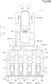
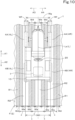
- the number of first working units 61a1 is smaller than the number of second working units 61a2 such as a case where the first working device 60A is the type I device 61 and the number of first working units 61a1 is two and the second working device 60B is the type I device 61 and the number of second working units 61a2 is four, if the working machine 1 having the first working device 60A linked thereto travels along the reference route L2 and the first working device 60A does the first work Jn, there occurs an unfinished region E1 as illustrated in FIG. 11A .
- the first working device 60A is the type II device 62
- the second working device 60B is the type I device 61
- the first working width Wa is smaller than the second working width Wb
- the working machine 1 having the first working device 60A connected thereto travels along the reference route L2 and the first working device 60A does the first work Jn, there occurs an overlapping work region E2, as illustrated in FIG. 11D .
- the working body 62a does work outside the work line R1 where the second working unit 61a2 has done work.
- the route creator 57d includes a second creator 57d2 instead of or in addition to the first creator 57d1, and the second creator 57d2 can create a travel route L (first route L1) for the first work Jn based on the second work Jn-1.
- the second creator 57d2 creates the travel route L for the first work Jn based on the travel route L for the second work Jn-1 and second information of the second working device 60B.
- the travel route L (reference route L2) for the second work Jn-1 may be hereinafter referred to as a second route L2
- the travel route L for the first work Jn may be hereinafter referred to as a first route L1.
- the second route L2 is a route along which the vehicle body 2 having the second working device 60B connected thereto moves, that is, a path for the second work
- the first route L1 is a route along which the vehicle body 2 having the first working device 60A connected thereto moves, that is, a path for the first work.
- a section line La of the first route L1 is referred to as a first portion La1
- a section line La of the second route L2 is referred to as a second portion La2.
- the second creator 57d2 can create the first route L1 based on a plurality of non-travelable lines R1 extending from one of opposite edges to the other of the agricultural field G (in the first direction B 1) and arranged at first interval(s) x.
- the plurality of non-travelable lines R1 are, for example, work lines R1 where work has been done at first interval(s) x from one of opposite edges to the other of the agricultural field G.
- the second creator 57d2 (route creator 57d) creates the first route L1 based on the plurality of non-travelable lines R1 (work lines R1) extending from one of opposite edges to the other of the agricultural field G (in the first direction B1) and arranged at first interval(s) x.
- the second creator 57d2 (route creator 57d) creates the first route L1 that prevents or reduces occurrence of the unfinished region E1 and the overlapping work region E2 as the travel route L for the first work Jn based on work in the preceding step.
- the route creator 57d switches between creation of the travel route L using the first creator 57d1 and creation of the travel route L using the second creator 57d2 in accordance with the state of the agricultural field G, that is, a work schedule within a certain period, and the status of a work plan.
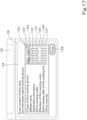
- the display controller 57 causes a selection screen D2 to be displayed on the display unit 56, as illustrated in FIG. 12 .
- the route creator 57d can switch between a "first mode” in which the first route L1 and the second route L2 are collectively created by the first creator 57d1 and the second creator 57d2 and a "second mode” in which only the second route L2 is created by a second creation mode by referring to the second work Jn-1.
- the selection screen D2 includes a selection portion 105, and receives the operation of selecting the "first mode” or the "second mode” when the operation for selection is performed on the selection portion 105.
- the working machine 1 includes a first work acquirer 57e, a second work acquirer 57f, a route acquirer 57g, a first acquirer 57h, and a determiner 57i.
- the display controller 57 of the display 55 also functions as the first work acquirer 57e, the second work acquirer 57f, the route acquirer 57g, and the determiner 57i.
- the display controller 57 of the display 55 also functions as the first work acquirer 57e, the second work acquirer 57f, the route acquirer 57g, and the determiner 57i in the present embodiment
- the controller 40 or the like may include the first work acquirer 57e, the second work acquirer 57f, the route acquirer 57g, and the determiner 57i, and the configuration thereof is not limited to the above configuration.
- the first work acquirer 57e acquires first information of the first working device 60A.
- the first information is information such as information unique to the first working device 60A and/or information relating to the first work Jn done by the first working device 60A.
- the first work acquirer 57e acquires, as the first information, the first working width (second interval) Wa and the number c1 of first working units 61a1.
- the first information acquired by the first work acquirer 57e is not limited to the first working width Wa and the number c1 of first working units 61a1, and information such as type, individual information, and model name of the first working device 60A, the unit working width Wc of the first working unit 61a1, the first interval x, and/or date and time of the first work may be acquired as the first information in addition to the first working width Wa and the number c1 of first working units 61a1.
- the first work acquirer 57e acquires, as the first information, information such as the type, individual information, and model name of the first working device 60A, the unit working width Wc, and the first interval x in addition to the first working width Wa and the number c1 of first working units 61a1.
- a feature of the first work acquirer 57e that acquires the first working width (second interval) Wa may be hereinafter referred to as a second acquirer 57e1.
- the second work acquirer 57f acquires the second information of the second working device 60B.
- the second information is information such as information unique to the second working device 60B and/or information relating to the second work Jn-1 done by the second working device 60B.
- the second work acquirer 57f acquires, as the second information, the second working width Wb and the number c2 of second working units 61a2.
- the second information acquired by the second work acquirer 57f is not limited to the second working width Wb and the number c2 of second working units 61a2, and information such as type, individual information, and model name of the second working device 60B, the unit working width Wc, the first interval x, and/or date and time of the second work may be acquired as the second information in addition to the second working width Wb and the number c2 of second working units 61a2.
- the second work acquirer 57f acquires, as the second information, information such as the type, the individual information, and the model name of the second working device 60B, the unit working width Wc, and the first interval x in addition to the second working width Wb and the number c2 of second working units 61a2.
- the route acquirer 57g acquires the second route L2.
- the route acquirer 57g acquires, as the second route L2, a travel route L corresponding to the second work Jn-1 among travel route(s) L created by the route creator 57d or, in a case where the travel route L corresponding to the second work Jn-1 is stored in a storage region of the controller 40 or the like, acquires the travel route L as the second route L2 from the storage region.
- the route acquirer 57g acquires at least a plurality of second portions La2 of the second route L2.
- the first acquirer 57h acquires data of the work lines R1 indicated by positions (latitude and longitude) and/or data of the work lines R1 indicated by a coordinate (an X axis and a Y axis) system based on the second portion(s) La2 acquired by the route acquirer 57g and the number c2 of second working units 61a2, the unit working width Wc, the first interval x, and the second portion La2 acquired by the second work acquirer 57f.
- the first acquirer 57h defines the work lines R1 based on the number of second working units 61a2, the unit working width Wc, and the first interval x acquired by the second work acquirer 57f and the second route L2 acquired by the route acquirer 57g to acquire the non-travelable lines R1 in the above embodiment
- a method of acquiring the non-travelable lines R1 is not limited to the above method.
- the non-travelable lines R1 (work lines R1) are stored in advance in a storage region such as the display storing unit 58 or an external server directly or indirectly communicable with the display 55 or the controller 40, the non-travelable lines R1 may be acquired from the storage region.
- the determiner 57i determines whether the second working device 60B is the type I device 61, the type II device 62, or the type III device based on the second information acquired by the second work acquirer 57f. The determiner 57i determines whether the second working device 60B is the type I device 61, the type II device 62, or the type III device based on the type of second working device 60B included in the second information.
- the determiner 57i determines whether the second working device 60B is the type I device 61, the type II device 62, or the type III device based on the information.
- the determination method is not limited to the above method, as long as the determiner 57i can determine whether the second working device 60B is the type I device 61, the type II device 62, or the type III device.
- the second creator 57d2 includes a line definer 157a and a setter 157b.
- the route creator 57d includes the line definer 157a and the setter 157b.
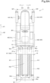
- the line definer 157a defines a plurality of travelable lines R2, which are regions other than the plurality of non-travelable lines R1 in the agricultural field G, based on the plurality of non-travelable lines R1 acquired by the first acquirer 57h. This is described based on an example case where the second working device 60B is the ridge maker 71 illustrated in FIG. 9A . Since the second working device 60B of FIG.
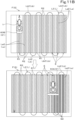
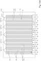
- 9A includes two working units 61a, if the working machine 1 travels from one of opposite edges to the other and from the other of the opposite edges to the one of the opposite edges of the agricultural field G (in the first direction B 1) five times, that is, if the second route L2 includes ten section lines La, twenty work lines R1 are formed and twenty-one travelable lines R2 are formed as illustrated in FIG. 13A .
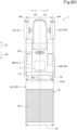
- the second working device 60B is the seed spreader 75 illustrated in FIG. 9B is described as an example. Since the second working device 60B of FIG. 9B includes four working units 61a, if the working machine 1 travels from one of the opposite edges to the other and from the other of the opposite edges to the one of the opposite edges of the agricultural field G (in the first direction B 1) 2.5 times, that is, if the second route L2 includes five section lines La, twenty work lines R1 are formed and twenty-one travelable lines R2 are formed as illustrated in FIG. 13B .
- the setter 157b sets, as the first portions La1, a path which extends from one of opposite edges to the other of the agricultural field G (in the first direction B1) and along which the traveling device 4 travels on the plurality of travelable lines R2, based on the plurality of travelable lines R2 defined by the line definer 157a. That is, the setter 157d can regard, as a candidate for the first portions La1, a path along the travelable lines R2 other than the travelable lines R2 corresponding to the second portions La2, in addition to the second portions La2.
- the setter 157b sets the first portions La1 in the following manner: the setter 157b extracts travelable lines R2 from the plurality of travelable lines R2, and sets the first portions La1 corresponding to the extracted travelable lines R2.
- the travel route L (section lines La) and the travelable lines R2 are in such a relationship that in a case where one travelable line R2 is selected from the plurality of travelable lines R2, the travel route L (section lines La) traveled by the first traveling unit 4L or the second traveling unit 4R when it travels along the travelable line R2 can be defined, and in a case where the travel route L (section lines La) is selected, travelable lines R2 traveled by the first traveling unit 4L and the second traveling unit 4R when the working machine 1 travels along the travel route L (section lines La) can be defined.
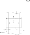
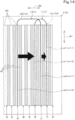
- the setter 157b shifts the plurality of second portions La2 starting from the rightmost second portion La2 on the drawing.
- the setter 157b calculates a shift amount based on the following expression (1). [Math. 1] w a ⁇ w b m ⁇ 1 2
- the setter 157b sets the plurality of first portions La1 by shifting the plurality of second portions La2 by the shift amount calculated by the above expression
- the interval between two adjacent first portions La1 of the plurality of first portions La1 is substantially equal to the second interval Wa. That is, the setter 157b sets the plurality of first portions La1 based on the second interval Wa included in the first information acquired by the second acquirer 57e1 so that the interval between two adjacent first portions La1 is substantially equal to the second interval Wa.
- the first working width Wa and the second working width Wb are equal to about a natural number multiple of the first interval x, and therefore the setter 157b can calculate the shift amount based on the number c2 of second working units 61a2 acquired by the second work acquirer 57f and the number c1 of first working units 61a1 acquired by the first work acquirer 57e. Specifically, the setter 157b (route creator 57d) calculates the shift amount based on the difference between the number c1 of first working units 61a1 and the number c2 of second working units 61a2 and the first interval x.
- the setter 157b calculates the shift amount based on any of the above calculation expressions and shifts the plurality of second portions La2. Note that in a case where the first working width Wa is larger than the second working width Wb (Wb ⁇ Wa) and the number c2 of second working units 61a2 is larger than the number c1 of first working units 61a1 (c2 ⁇ c1), that is, in a case where the shift amount calculated using the expression (1) or (2) is a positive number, the setter 157b shifts the plurality of second portions La2 by the shift amount from one of the opposite edges (right edge) toward the other (left edge) in the second direction B2. In the present embodiment, in a case where the shift amount calculated using the expression (1) or (2) is a positive number, the setter 157b shifts the plurality of second portions La2 leftward in the drawing by the shift amount.
- the setter 157b shifts the plurality of second portions La2 by the shift amount from the other of the opposite edges (left edge) toward the one edge (right edge) of the second direction B2.
- the setter 157b shifts the plurality of second portions La2 rightward in the drawing by the shift amount.
- the setter 157b not only sets the first portions La1 by shifting the second portions La2, but also newly creates first portions La1 spaced apart from one another by the first working width Wa on the travelable lines R2. Specifically, the setter 157b newly creates as many first portions La1 as the difference between (i) the greatest common measure of the first working width Wa and the dimension of the agricultural field G in the second direction B2 and (ii) the number of second portions La2, and the second creator 57d2 connects adjacent first portions La1 to form a first turning portion Lb1. In this way, the route creator 57d (second creator 57d2) creates the first route L1.
- the shift amount calculated based on the expression (2) is a negative number
- the setter 157b shifts the plurality of second portions La2 rightward in the drawing by the shift amount.
- the setter 157b newly creates as many first portions La1 as the difference (five) between the greatest common measure (ten) of the first working width Wa and the dimension of the agricultural field G in the second direction B2 and the number (five) of second portions La2, and the second creator 57d2 connects adjacent first portions La1 to form a first turning portion Lb1.
- the setter 157b extracts the travelable lines R2 that reduce the unfinished region E1 and the overlapping work region E2 so that the unfinished region E1 and the overlapping work region E2 would not be generated and thus sets the first portions La1 based on the working width W included in the first information acquired by the first work acquirer 57e.
- the second work input screen D3 may receive input of the model of the working device 60, and the second work acquirer 57f may acquire the second information from a table stored in advance in the display storing unit 58.
- the second information is stored as a table including the model of the working device 60, and the second information is acquired using the model of the working device 60 as individual information.
- the second work acquirer 57f may acquire the second information including the second working width Wb and the number c2 of second working units 61a2 based on an image taken by an imager provided in or on the working machine 1 and/or information detected by a detector such as a sensor.
- the first working device 60A is the type II device 62 or the type III device 63
- no information is input in the ninth region 122
- the first work acquirer 57e does not acquire the number c1 of first working units 61a1.
- the first work acquirer 57e acquires the first information including the first working width Wa and the number c1 of first working units 61a1 based on the information input on the screen of the display unit 56
- a method of inputting the first information is not limited to the above method, and the source of acquisition is not limited to the information input on the first work input screen D4.
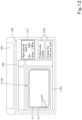
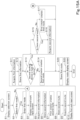
- the second work acquirer 57f checks whether or not the second information of the second work Jn-1 preceding the first work Jn for which the first information was acquired in S20 is stored in the display storing unit 58 (S22).
- the second creator 57d2 (route creator 57d) creates the first route L1 based on the first information acquired by the first work acquirer 57e, the second information acquired by the second work acquirer 57f, and the second route L2 acquired by the route acquirer 57g in a case where the non-travelable lines R1 are formed in the agricultural field G.
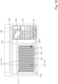
- the display controller 57 acquires the vehicle body position VP detected by the position detector (positioning device) 50 and causes the current position of the working machine 1 to be displayed as an icon 130a on the route display portion 130 based on the vehicle body position VP.
- the third information display portion displays the first information acquired by the first work acquirer 57e or the second information acquired by the second work acquirer 57f in response to an operation of the switching button 131.
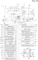
- the controller 40 includes an auto-steering controller 40a, as illustrated in FIG. 19 .
- the auto-steering controller 40a includes electric/electronic circuit(s) provided in the controller 40, program(s) stored in a CPU and/or the like, and/or the like.
- the auto-steering controller 40a controls a steering motor 38 of an auto-steering mechanism 37 so that the vehicle body 2 travels along the travel route L based on a control signal output from the controller 40.
- the auto-steering controller 40a may set a final steering angle of auto-steering based on a steering angle determined based on deviation (positional deviation) and a steering angle determined based on orientation (orientation deviation).
- Setting of the steering angle of auto-steering in the above embodiment is an example and is not restrictive.
- the automatic travel controller 40b controls the traveling speed so that the traveling speed on the section line La and the traveling speed on the turning portion Lb are different. For example, the automatic travel controller 40b sets the traveling speed on the section line La to a speed ⁇ . On the other hand, the automatic travel controller 40b sets the traveling speed on the turning portion Lb to a speed ⁇ lower than the speed ⁇ ( ⁇ ⁇ ⁇ ). Note that the automatic travel controller 40b may divide the section line La into a plurality of sections and set traveling speeds in the sections to different speeds, and control of the traveling speeds is not limited to the above configuration.
- the automatic travel controller 40b controls the steering motor 38 of the auto-steering mechanism 37 so that the working machine 1 travels along the travel route L, by a method similar to the auto-steering controller 40a.
- a working machine 1 as has been described includes a vehicle body 2, a first working device 60A attachable to the vehicle body 2, a traveling device 4 on the vehicle body 2, a first acquirer 57h to acquire a plurality of non-travelable lines R1 that extend from one of opposite edges of an agricultural field G to the other and are arranged at a first interval or intervals x, and a route creator 57d to create, based on the plurality of non-travelable lines R1 acquired by the first acquirer 57h, a first route L1 including a plurality of first portions La1 to be traveled by the vehicle body 2 and extending from the one of the opposite edges to the other of the agricultural field G, wherein the traveling device 4 includes portions that are spaced apart from each other by a distance corresponding to the first interval x, and the route creator 57d includes a line definer 157a to define, as a plurality of travelable lines R2, regions of the agricultural field G other than the plurality of non-travelable lines R1 based on the plurality of non
- the working machine 1 can travel along the travelable lines R2 while avoiding the non-travelable lines R1, and therefore, in a case where the setter 157b sets the first portions La1 based on the plurality of travelable lines R2, the route creator 57d can create the first portions La1 along which the working machine 1 can travel without entering the non-travelable lines R1. This allows the working machine 1 to efficiently do work in the agricultural field G without traveling on the non-travelable lines R1.
- the working machine 1 further includes a second acquirer 57e1 to acquire a second interval Wa which is a first working width Wa.
- the setter 157b sets the plurality of first portions La1 such that an interval between two adjacent section lines La is substantially equal to the second interval Wa based on the second interval Wa acquired by the second acquirer 57e1.
- the setter 157b can eliminate or reduce the likelihood that regions where the first working device 60A does work are separated from each other or overlap each other in a case where the working machine 1 travels along two adjacent section lines La. Therefore, the working machine 1 makes it possible to prevent or reduce the generation of the unfinished regions E1 where the first working device 60A has not done work and the overlapping work regions E2 where the first working device 60A does work twice or more.
- the first acquirer 57h acquires, as the plurality of non-travelable lines R1, a plurality of work lines R1 which are arranged at the first interval or intervals x and in which work has been done from the one of the opposite edges to the other of the agricultural field G or from the other of the opposite edges to the one of the opposite edges of the agricultural field G.
- the working machine 1 that travels along the first portions La1 can do work without entering the plurality of work lines R1. This allows the working machine 1 to do work more efficiently without damaging regions where work has been done already.
- the working machine 1 further includes a position detector 50 to detect a position of the vehicle body 2, and an auto-steering controller 40a to control steering of the traveling device 4 based on the position of the vehicle body 2 detected by the position detector 50 and the first route L1 created by the route creator 57d.
- the auto-steering controller 40a causes the working machine 1 to travel along the first route L1 (first portions La1) by controlling steering without the need for the operator to steer the working machine 1. This allows the working machine 1 to efficiently do work in the agricultural field G without traveling on the non-travelable lines R1. It is therefore possible to further improve work performance of the working machine 1.
- a working machine 1 as has been described includes a vehicle body 2, a first working device 60A attachable to the vehicle body 2 to do first work, a traveling device 4 on the vehicle body 2, a first work acquirer 57e to acquire first information of the first working device 60A, a second work acquirer 57f to acquire second information of a second working device 60B to do second work before the first work, a route acquirer 57g to acquire a second route L2 which is a path for the second work, and a route creator 57d to create a first route L1 which is a path for the first work and includes a plurality of first portions La1 extending from one of opposite ends to the other of an agricultural field G and spaced apart from each other, wherein the route acquirer 57g acquires, as the second route L2, a plurality of second portions La2 extending from the one of the opposite edges to the other of the agricultural field G and spaced apart from each other, and the route creator 57d creates the plurality of first portions La1 by shifting the plurality of
- the route creator 57d can create the first route L1 including the first portions La1 by shifting the second portions La2 which are a path along which the second work has been done, that is, by changing the second route L2. Therefore, the first route L1 (first portions La1) can be easily created while omitting input of various kinds of information included in the second route L2. Furthermore, work (first work) corresponding to the second work can be done more appropriately.
- the working machine 1 by traveling along the first portions La1, makes it possible to prevent or reduce the generation of the unfinished regions E1 where the first working device 60A has not done work and the overlapping work regions E2 where the first working device 60A does work twice or more.
- the route creator 57d creates the first portions La1 by shifting the plurality of second portions La2 by a product of (i) the difference between the first working width Wa acquired by the first work acquirer 57e and the second working width Wb acquired by the second work acquirer 57f and (ii) a natural number multiple of 1/2.
- the working machine 1 can prevent or reduce the generation of the unfinished region E1 of the first working device 60A and the overlapping work region E2 of the first working device 60A easily by a simple method.
- the first working device 60A includes a first working unit 61a1 or a plurality of first working units 61a1 arranged at a first interval or intervals x in a width direction.
- the second working device 60B includes a second working unit 61a2 or a plurality of second working units 61a2 arranged at the first interval or intervals x in the width direction.
- the first work acquirer 57e acquires the number c1 of first working units 61a1 as the first information.
- the second work acquirer 57f acquires the number c2 of second working units 61a2 as the second information.
- the route creator 57d creates the plurality of first portions La1 by shifting the plurality of second portions La2 based on (i) a difference between the number c1 of first working units 61a1 acquired by the first work acquirer 57e and the number c2 of second working units 61a2 acquired by the second work acquirer 57f and (ii) the first interval x.
- the route creator 57d can locate the first portions La1 at positions corresponding to the first working units 61a1 and the second working units 61a2 when creating the first portions La1 by shifting the second portions La2.
- the first working units 61a1 can do work reliably at positions where the second working units 61a2 have done work. This makes it possible to eliminate or reduce the likelihood that regions where the first working device 60A does work are separated from each other or overlap each other in a case where the working machine 1 travels along the first portions La1.
- the route creator 57d creates the plurality of first portions La1 by shifting the plurality of second portions La2 by a product of (i) the difference between the number c1 of first working units 61a1 acquired by the first work acquirer 57e and the number c2 of second working units 61a2 acquired by the second work acquirer 57f, (ii) the first interval x, and (iii) a natural number multiple of 1/2.
- the working machine 1 can prevent or reduce the generation of the unfinished regions E1 of the first working device 60A and the overlapping work regions E2 of the first working device 60A reliably by a simple method.
- the first work acquirer 57e acquires a first working width Wa of the first working device 61A as the first information.
- the route creator 57d creates the second route L2 based on the first working width Wa.
- the route acquirer 57g acquires the second route L2 created by the route creator 57d.
- the working machine further includes a linkage 30 to selectively connect the first working device 60A or the second working device 60B to the vehicle body 2.
- the first route L1 is a path traveled by the vehicle body 2 having the first working device 60A attached thereto via the linkage 30.
- the second route L2 is a path traveled by the vehicle body 2 having the second working device 60B attached thereto via the linkage 30.
- the present invention is also applicable to a case where the number of working units 61a of the type I device 61 is an odd number.
- the present invention is applicable to a case where both of the number of first working units 61a1 and the number of second working units 61a2 are odd numbers.
Landscapes
- Life Sciences & Earth Sciences (AREA)
- Engineering & Computer Science (AREA)
- Mechanical Engineering (AREA)
- Soil Sciences (AREA)
- Environmental Sciences (AREA)
- Guiding Agricultural Machines (AREA)
Applications Claiming Priority (2)
| Application Number | Priority Date | Filing Date | Title |
|---|---|---|---|
| JP2021138769 | 2021-08-27 | ||
| PCT/JP2022/031719 WO2023027072A1 (fr) | 2021-08-27 | 2022-08-23 | Machine de travail |
Publications (2)
| Publication Number | Publication Date |
|---|---|
| EP4393285A1 true EP4393285A1 (fr) | 2024-07-03 |
| EP4393285A4 EP4393285A4 (fr) | 2025-09-17 |
Family
ID=85322843
Family Applications (1)
| Application Number | Title | Priority Date | Filing Date |
|---|---|---|---|
| EP22861360.0A Pending EP4393285A4 (fr) | 2021-08-27 | 2022-08-23 | Machine de travail |
Country Status (6)
| Country | Link |
|---|---|
| US (1) | US20240244988A1 (fr) |
| EP (1) | EP4393285A4 (fr) |
| JP (1) | JP7693814B2 (fr) |
| CN (1) | CN117881275A (fr) |
| AU (1) | AU2022333603B2 (fr) |
| WO (1) | WO2023027072A1 (fr) |
Families Citing this family (1)
| Publication number | Priority date | Publication date | Assignee | Title |
|---|---|---|---|---|
| WO2025142755A1 (fr) * | 2023-12-26 | 2025-07-03 | 株式会社クボタ | Repiqueuse |
Family Cites Families (16)
| Publication number | Priority date | Publication date | Assignee | Title |
|---|---|---|---|---|
| JP3673285B2 (ja) * | 1992-10-09 | 2005-07-20 | 櫻護謨株式会社 | 屋外作業自動化システム |
| US6205381B1 (en) * | 1999-03-26 | 2001-03-20 | Caterpillar Inc. | Method and apparatus for providing autoguidance for multiple agricultural machines |
| DE102006015203A1 (de) * | 2006-03-30 | 2007-11-15 | Claas Selbstfahrende Erntemaschinen Gmbh | Verfahren zur Steuerung von landwirtschaftlichen Maschinensystemen |
| JP2009240181A (ja) * | 2008-03-28 | 2009-10-22 | Kubota Corp | 刈取収穫機 |
| JP5952611B2 (ja) * | 2012-03-28 | 2016-07-13 | 国立研究開発法人農業・食品産業技術総合研究機構 | 走行制御装置 |
| JP6497546B2 (ja) * | 2015-02-06 | 2019-04-10 | 国立研究開発法人農業・食品産業技術総合研究機構 | 走行制御装置 |
| JP6502221B2 (ja) | 2015-09-14 | 2019-04-17 | 株式会社クボタ | 作業車支援システム |
| JP6571017B2 (ja) * | 2016-01-26 | 2019-09-04 | ヤンマー株式会社 | 農業用作業車両 |
| JP6802076B2 (ja) * | 2017-01-24 | 2020-12-16 | 株式会社クボタ | 走行経路生成システム |
| JP7086616B2 (ja) * | 2018-01-22 | 2022-06-20 | 株式会社クボタ | 農業支援装置及び農業支援システム |
| US11641790B2 (en) * | 2018-05-09 | 2023-05-09 | Deere & Company | Method of planning a path for a vehicle having a work tool and a vehicle path planning system |
| KR102845158B1 (ko) * | 2018-12-21 | 2025-08-12 | 가부시끼 가이샤 구보다 | 파식계 작업기 및 파식계 작업기의 자동 주행 제어 시스템, 포장 작업차 및 주행 경로 생성 시스템 |
| JP7281123B2 (ja) * | 2019-07-18 | 2023-05-25 | ヤンマーパワーテクノロジー株式会社 | 作業情報生成装置 |
| JP7132191B2 (ja) * | 2019-08-08 | 2022-09-06 | ヤンマーパワーテクノロジー株式会社 | 作業車両用の自動走行システム |
| JP7353877B2 (ja) * | 2019-09-06 | 2023-10-02 | 株式会社クボタ | 作業車両及び作業車両の作業支援装置 |
| US11999379B2 (en) * | 2021-08-05 | 2024-06-04 | Cnh Industrial America Llc | Systems and methods for controlling a work vehicle |
-
2022
- 2022-08-23 WO PCT/JP2022/031719 patent/WO2023027072A1/fr not_active Ceased
- 2022-08-23 EP EP22861360.0A patent/EP4393285A4/fr active Pending
- 2022-08-23 JP JP2023543930A patent/JP7693814B2/ja active Active
- 2022-08-23 AU AU2022333603A patent/AU2022333603B2/en active Active
- 2022-08-23 CN CN202280058422.7A patent/CN117881275A/zh active Pending
-
2024
- 2024-02-23 US US18/585,367 patent/US20240244988A1/en active Pending
Also Published As
| Publication number | Publication date |
|---|---|
| JP7693814B2 (ja) | 2025-06-17 |
| JPWO2023027072A1 (fr) | 2023-03-02 |
| WO2023027072A1 (fr) | 2023-03-02 |
| AU2022333603B2 (en) | 2025-09-25 |
| EP4393285A4 (fr) | 2025-09-17 |
| US20240244988A1 (en) | 2024-07-25 |
| CN117881275A (zh) | 2024-04-12 |
| AU2022333603A1 (en) | 2024-03-07 |
Similar Documents
| Publication | Publication Date | Title |
|---|---|---|
| JP7313989B2 (ja) | 農業機械 | |
| US12120970B2 (en) | Work vehicle and work assistance apparatus for work vehicle | |
| CN116058124B (zh) | 作业车辆及其行驶路径设定系统 | |
| US20220279698A1 (en) | Working machine | |
| EP4406395A1 (fr) | Système d'aide au déplacement pour machine agricole | |
| CN109121511B (zh) | 行驶路径设定系统以及作业车 | |
| US12369508B2 (en) | Travel line creation system for agricultural machine | |
| US12514143B2 (en) | Agricultural machine, agricultural work assistance apparatus, and agricultural work assistance system | |
| US20240196779A1 (en) | Working machine | |
| US20240244988A1 (en) | Working machine | |
| US20230292645A1 (en) | Traveling assistance system for agricultural machine | |
| EP4079124B1 (fr) | Machine de travail | |
| US20230380327A1 (en) | Agricultural work assistance apparatus, agricultural work assistance system, and agricultural machine | |
| JP7598562B2 (ja) | 作業車両 | |
| JP2020101467A (ja) | 圃場形状生成システム及び農作業車 | |
| JP7113683B2 (ja) | 圃場作業機 | |
| JP7805915B2 (ja) | 農作業支援装置、農作業支援システム、農業機械、走行ライン作成方法 | |
| WO2025142702A1 (fr) | Dispositif de support de travail, machine de travail et procédé de support de travail | |
| JP2024090660A (ja) | 農作業支援装置、農作業支援システム、農業機械、走行ライン作成方法 |
Legal Events
| Date | Code | Title | Description |
|---|---|---|---|
| STAA | Information on the status of an ep patent application or granted ep patent |
Free format text: STATUS: THE INTERNATIONAL PUBLICATION HAS BEEN MADE |
|
| PUAI | Public reference made under article 153(3) epc to a published international application that has entered the european phase |
Free format text: ORIGINAL CODE: 0009012 |
|
| STAA | Information on the status of an ep patent application or granted ep patent |
Free format text: STATUS: REQUEST FOR EXAMINATION WAS MADE |
|
| 17P | Request for examination filed |
Effective date: 20240229 |
|
| AK | Designated contracting states |
Kind code of ref document: A1 Designated state(s): AL AT BE BG CH CY CZ DE DK EE ES FI FR GB GR HR HU IE IS IT LI LT LU LV MC MK MT NL NO PL PT RO RS SE SI SK SM TR |
|
| DAV | Request for validation of the european patent (deleted) | ||
| DAX | Request for extension of the european patent (deleted) | ||
| A4 | Supplementary search report drawn up and despatched |
Effective date: 20250814 |
|
| RIC1 | Information provided on ipc code assigned before grant |
Ipc: A01B 69/00 20060101AFI20250808BHEP |